US637726A - Crib for docks. - Google Patents
Crib for docks. Download PDFInfo
- Publication number
- US637726A US637726A US71074299A US1899710742A US637726A US 637726 A US637726 A US 637726A US 71074299 A US71074299 A US 71074299A US 1899710742 A US1899710742 A US 1899710742A US 637726 A US637726 A US 637726A
- Authority
- US
- United States
- Prior art keywords
- crib
- sections
- section
- joint
- plates
- Prior art date
- Legal status (The legal status is an assumption and is not a legal conclusion. Google has not performed a legal analysis and makes no representation as to the accuracy of the status listed.)
- Expired - Lifetime
Links
Images
Classifications
-
- E—FIXED CONSTRUCTIONS
- E02—HYDRAULIC ENGINEERING; FOUNDATIONS; SOIL SHIFTING
- E02D—FOUNDATIONS; EXCAVATIONS; EMBANKMENTS; UNDERGROUND OR UNDERWATER STRUCTURES
- E02D29/00—Independent underground or underwater structures; Retaining walls
- E02D29/02—Retaining or protecting walls
- E02D29/0216—Cribbing walls
-
- Y—GENERAL TAGGING OF NEW TECHNOLOGICAL DEVELOPMENTS; GENERAL TAGGING OF CROSS-SECTIONAL TECHNOLOGIES SPANNING OVER SEVERAL SECTIONS OF THE IPC; TECHNICAL SUBJECTS COVERED BY FORMER USPC CROSS-REFERENCE ART COLLECTIONS [XRACs] AND DIGESTS
- Y10—TECHNICAL SUBJECTS COVERED BY FORMER USPC
- Y10T—TECHNICAL SUBJECTS COVERED BY FORMER US CLASSIFICATION
- Y10T403/00—Joints and connections
- Y10T403/70—Interfitted members
- Y10T403/7075—Interfitted members including discrete retainer
Definitions
- This invention relates to a crib or caisson for docks, wharves, breakwaters, and similar marine structures, and more particularly to a crib composed of a series of similar metallic sections which are connected together end to end by vertical sliding joints, the interlocking parts of which are formed on adjoining sections, so that by joining one section to another a crib or pier may be constructed of any desired length.
- One of the objects of my invention is to construct the crib-sections in such manner that they can be built complete at the factory and readily assembled where the dock or similar structure is to be erected and so that the sections can accommodate themselves to any slight imperfection of the joints which connect the same, thus permitting the parts of the joints to be made with less exactness and reducing their cost of production.
- My invention has the further object to provide a strong and reliable joint for the cribsections which is simple in construction and cheaply produced.
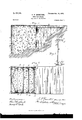
- Figure l is a longitudinal sectional elevation of a dock or pier embodying my invention.
- Fig. 2 is a top plan view thereof, partly in section.
- Fig. 3 is a detached top plan view of one of the crib-sections.
- Fig. 4 is a vertical longitudinal section of the dock in process of construction.
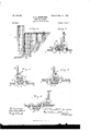
- Fig. 5 is an enlarged horizontal section of one of the interlocking slip-joints which connect adjoining crib-sections.
- Figs. 6, 7, and 8 are similar sections of modified constructions of said joints.
- Each section of my improved crib or caisson consists of a pair ⁇ of upright metallic side plates A A, which are securely connected together at or near one of their upright edges, preferably their front edge, by a number of cross bars or ties B, which are arranged at Serial No. 710,742. (No model.)
- the crib is made up of a series of such sections, which are arranged end to en d or one in advance of another, and the adjoining sections are connected together by interlocking joints, preferably upright slip or sliding joints.
- interlocking joints preferably upright slip or sliding joints.
- the form of joint preferred for this pur'pose is shown in Figs.
- each tenon c is preferably formed on a vertical angle-bar c', which is riveted or otherwise secured to the inner side of the adjacent side plate A and extends from the top tothe bottom thereof.
- the neck of the tenon extends across the flush joint e, between t-he side plates of adjoining crib-sections, and the head of the tenon bears at its outer side against the inner side of the opposing side plate.
- the corresponding groove of the slip-joint is formed by a vertical channelbar d', which opens outwardly and which is provided with a laterally-extending Iiange d2, which is riveted or otherwise secured to the adjacent side plate A of the crib-section.
- This channel-bar extends rearwardly beyond the flush joint e, between the side plates of adjoining crib-sections, so as to coincide with the tenon c of the adjoining section, and the flange forming the outer wall of the channel terminates at a distance from the side plates to leave the necessary intervening space for the neck of the adjacent tenon c.
- the side plates of the foremost or outermost crib-section are connected at their front edgesV by a tight l plate F, which extends throughout the depth of the plates and forms the closed outer end of the pier or dock.
- This front plate is secured to the side plates preferably by upright angle-bars f, arranged in the front corners of said section, as shown in Fig. 2, and this plate is preferably stiened by a series of horizontal braces g, extending from the central portion of the plate to the inner sides of the side plates of the ⁇ foremost crib-section.
- My improved crib-sections are preferably constructed wholly of sheet metal, and the sections are made of different lengths, as may be required by the varying depths or undulations of the bed of lthe river or other body of water in' which the crib is to be built.
- a crib-section of approximately the required length is sunk into the bed of the lake or stream, preferably with its open side toward the rear or inner end of the dock, as shown in the drawings.
- another crib-section is loweredin the same position in front of the rstnamed section and interlocked therewith by 4o properlyengaging the lower ends of the channel-,bars d of the second section with the up-- perends of the tenons c of the first section and sliding the second section down into placeV on the first section, whereby the two sections are conveniently and reliably connected t0- gether and at the same time properly alined without requiring special care.
- the remaining crib-sections are successively added in the same manner until all the sections are assembled, and when the sections are united in this manner the adjoining side plates of the series of sections form two parallel side walls, connected at intervals by the cross-bars B and at their front ends bythe tight plate F.
- the rectangular channel or inclosure so formed is iilled with earth, stone, concrete, or other suitable material to complete the crib.
- the usual floor-planks h of the dock or pier may be supported upon the upper ends of the readily assembled when required.
- Vcon-l structing the sections of side plates which are originally connected together only at one edgesay their-'front edgethe free rear portions'of the plates can be sprung'laterally to a limited extent to facilitate the interlocking of the parts of the section-joints incase the itof the parts is somewhat imperfect.
- the side plates are securely connected by the cross-bars B, the width of the plates alfords sufficient elasticity to permit o'f their being .sprung as described.
- This yielding feature of the sides of the sections allows the joints to be madeless exact and permits a less skilled class of labor toA be employed in the manufacture ofthe sections, thereby reducing their'cost correspondingly.
- joints may be employed for connecting the crib-sections instead of the joint shown in Figs. 2 and 5.
- the tenen of the joint may be Lfshaped, as shown at c:fs in Fig. 7, and the head of the same and the channel-bar d4 be arranged on the outer side of the side plate of the crib-y sections. In this case the rneck of the tenon passes outwardly between the opposing edges vof adjoining side plates.
- a Z-shaped Atenon c4 is employed, which has its head arranged on the outer side of the side plates, and the channel-bar d5, which receives the tenon, is' alsolocated on the outer side of the plate, as the joint shown in Fig. 7.
- the bar carrying the tenon has at its fron-t edge an upright flange c5 for the attachment of the cross-bars B, while in the joint shown inV Fig. 8 said iiange is formed at the rear edge of the bar which carries thevtenon.-
- the head of the vtenon is confined laterally be tween the channel-bar and the opposingside of the side plate to which the channel-bar is secured.
- Acri-b for docks, &c. composed of separate sections, each of which consists of a pair of upright side plates and a cross bar or tie which connects Asaid plates near one end of the section, the section being provided at its front and rear ends with locking devices adapted to engage with corresponding locking devicesv ofadjoining crib-sections, substantially as set forth.
- a cribsection composed of uprightl side plates and a cross bar or tie which connects the side plates near one of their upright edges, whereby said plates are allowed to yield laterally to a limited extent at ⁇ their opposite free edges, said side plates A and the uppermost cross-bars plates being provided at theirfree edges with locking devices which are adapted to engage with corresponding locking devices of an ad. joining cri b-rsection, substantially as set forth.
- the mortise member of the joint being arranged on one of the iut-erlocked plates and the tenon being arranged on the adjoining plate and conned in a lateral direction between the mortise member and the opposing side of the plate which carries the mortise member, ⁇ substantially as set forth.
Description
om 9 m w.. v. 0 N d 8 .I .h 0 :1l a P N. o s I E R Du A G D A. m 2 71, 7 3 6 nw N GRIB FOR DDCKS.
(Application led Mar. 28, 1899.)
2 Sheets-Sheet 1.
(No Model.)
U l lI me nomas Crans w. wmouwo.. wnsnmmnu. u. c.
No. 637,726. Y Patented um). 2|, i899.
A. n. GAnRETsoN.
(Application led Mar. 28, 1899.)
2 Sheets-Sheet `2.
(No Model.)
7??)5/1/655 es J UNITED- STATES I PATENT OFFICE.
ALBERT D. GARRETSON, OF BUFFALO, NEW YORK.
CRIB FOR DOCKS.
SPECIFICATION forming part `of Letters Patent No. 637,726, dated November 21, 1899.
Application filed March Z8, 1899.
To all whom. t may concern:
Be it known that I, ALBERT D. GARRETsoN, a citizen of the United States, residing at Buffalo, in the county of Erie and State of New York, have invented new and useful Improvements in Cribs for`Docks, dac., of which the following is aspecication.
This invention relates to a crib or caisson for docks, wharves, breakwaters, and similar marine structures, and more particularly to a crib composed of a series of similar metallic sections which are connected together end to end by vertical sliding joints, the interlocking parts of which are formed on adjoining sections, so that by joining one section to another a crib or pier may be constructed of any desired length. t
One of the objects of my invention is to construct the crib-sections in such manner that they can be built complete at the factory and readily assembled where the dock or similar structure is to be erected and so that the sections can accommodate themselves to any slight imperfection of the joints which connect the same, thus permitting the parts of the joints to be made with less exactness and reducing their cost of production.
My invention has the further object to provide a strong and reliable joint for the cribsections which is simple in construction and cheaply produced.
In the accompanying drawings, consisting of two sheets, Figure l is a longitudinal sectional elevation of a dock or pier embodying my invention. Fig. 2 is a top plan view thereof, partly in section. Fig. 3 is a detached top plan view of one of the crib-sections. Fig. 4 is a vertical longitudinal section of the dock in process of construction. Fig. 5 is an enlarged horizontal section of one of the interlocking slip-joints which connect adjoining crib-sections. Figs. 6, 7, and 8 are similar sections of modified constructions of said joints.
Like letters of reference refer to like parts in the several figures.
Each section of my improved crib or caisson consists of a pair` of upright metallic side plates A A, which are securely connected together at or near one of their upright edges, preferably their front edge, by a number of cross bars or ties B, which are arranged at Serial No. 710,742. (No model.)
l suitable intervals throughout the depth of the side plates, as shown in Figs. l and 4, forming a practically three-sided crib-section open at its upper and lower ends, as most clearly shown in Fgz. The crib is made up of a series of such sections, which are arranged end to en d or one in advance of another, and the adjoining sections are connected together by interlocking joints, preferably upright slip or sliding joints. The form of joint preferred for this pur'pose is shown in Figs. 2 and 5, and `consists of an upright rib or tenon o, arranged on or secured to the inner side of one of the interlocked plates at one of its upright edges, and a corresponding upright groove or mortise ol, arranged on the inner side of the adjoining plate, receiving the tenon of the other plate. Each tenon c is preferably formed on a vertical angle-bar c', which is riveted or otherwise secured to the inner side of the adjacent side plate A and extends from the top tothe bottom thereof. The neck of the tenon extends across the flush joint e, between t-he side plates of adjoining crib-sections, and the head of the tenon bears at its outer side against the inner side of the opposing side plate. The corresponding groove of the slip-joint is formed by a vertical channelbar d', which opens outwardly and which is provided with a laterally-extending Iiange d2, which is riveted or otherwise secured to the adjacent side plate A of the crib-section. This channel-bar extends rearwardly beyond the flush joint e, between the side plates of adjoining crib-sections, so as to coincide with the tenon c of the adjoining section, and the flange forming the outer wall of the channel terminates at a distance from the side plates to leave the necessary intervening space for the neck of the adjacent tenon c. By extending the tenons of one crib-section beyond the joint between the side plates of adjoining crib-sections in this manner the tenon is confined in a lateral direction between the channel-bar CZ and the opposing inner side of the side plate A, to which the channel-bar is fastened, thus utilizing the side plate as a part of the joint. This simplifies the construction of the joint and enables the bars forming the tenon and the groove to be rolled at a correspondingly-reduced cost. In this joint the ICO erably formed with the upright inwardly-ex-V tending tlanges c2, to which the ends of the cross-bars B are secured by rivets or other means. If desired, such an attaching-fiange may be formed `on the channel bar or groove member of each joint, as shown at d3 in Fig. 6. Y
The side plates of the foremost or outermost crib-section are connected at their front edgesV by a tight l plate F, which extends throughout the depth of the plates and forms the closed outer end of the pier or dock. This front plate is secured to the side plates preferably by upright angle-bars f, arranged in the front corners of said section, as shown in Fig. 2, and this plate is preferably stiened by a series of horizontal braces g, extending from the central portion of the plate to the inner sides of the side plates of the `foremost crib-section.
My improved crib-sections are preferably constructed wholly of sheet metal, and the sections are made of different lengths, as may be required by the varying depths or undulations of the bed of lthe river or other body of water in' which the crib is to be built.
In building a crib 4in accordance with my invention a crib-section of approximately the required length is sunk into the bed of the lake or stream, preferably with its open side toward the rear or inner end of the dock, as shown in the drawings. After properly plac- V ing this section another crib-section is loweredin the same position in front of the rstnamed section and interlocked therewith by 4o properlyengaging the lower ends of the channel-,bars d of the second section with the up-- perends of the tenons c of the first section and sliding the second section down into placeV on the first section, whereby the two sections are conveniently and reliably connected t0- gether and at the same time properly alined without requiring special care. The remaining crib-sections are successively added in the same manner until all the sections are assembled, and when the sections are united in this manner the adjoining side plates of the series of sections form two parallel side walls, connected at intervals by the cross-bars B and at their front ends bythe tight plate F. The rectangular channel or inclosure so formed is iilled with earth, stone, concrete, or other suitable material to complete the crib.
The usual floor-planks h of the dock or pier may be supported upon the upper ends of the readily assembled when required. By Vcon-l structing the sections of side plates which are originally connected together only at one edgesay their-'front edgethe free rear portions'of the plates can be sprung'laterally to a limited extent to facilitate the interlocking of the parts of the section-joints incase the itof the parts is somewhat imperfect. Although'the side plates are securely connected by the cross-bars B, the width of the plates alfords sufficient elasticity to permit o'f their being .sprung as described. This yielding feature of the sides of the sections allows the joints to be madeless exact and permits a less skilled class of labor toA be employed in the manufacture ofthe sections, thereby reducing their'cost correspondingly.
Other forms of joints may be employed for connecting the crib-sections instead of the joint shown in Figs. 2 and 5. For example, the tenen of the joint may be Lfshaped, as shown at c:fs in Fig. 7, and the head of the same and the channel-bar d4 be arranged on the outer side of the side plate of the crib-y sections. In this case the rneck of the tenon passes outwardly between the opposing edges vof adjoining side plates.
`In the modified construction of the joint shown in Fig. 8 substantially a Z-shaped Atenon c4 is employed, which has its head arranged on the outer side of the side plates, and the channel-bar d5, which receives the tenon, is' alsolocated on the outer side of the plate, as the joint shown in Fig. 7. In the joint shown in Fig. 7 the bar carrying the tenon has at its fron-t edge an upright flange c5 for the attachment of the cross-bars B, while in the joint shown inV Fig. 8 said iiange is formed at the rear edge of the bar which carries thevtenon.- In both of these modifications, as in the joint shown in Figs. 2and 5, the head of the vtenon is confined laterally be tween the channel-bar and the opposingside of the side plate to which the channel-bar is secured.
- I claim as my invention- 1. Acri-b for docks, &c., composed of separate sections, each of which consists of a pair of upright side plates and a cross bar or tie which connects Asaid plates near one end of the section, the section being provided at its front and rear ends with locking devices adapted to engage with corresponding locking devicesv ofadjoining crib-sections, substantially as set forth.
2. In a sectional crib for docks, &c., a cribsection composed of uprightl side plates and a cross bar or tie which connects the side plates near one of their upright edges, whereby said plates are allowed to yield laterally to a limited extent at `their opposite free edges, said side plates A and the uppermost cross-bars plates being provided at theirfree edges with locking devices which are adapted to engage with corresponding locking devices of an ad. joining cri b-rsection, substantially as set forth.
'3. The combination of a pair of adjoining j crib-sections, each having upright side plates which are connected with the plates of the adjoining section by an upright tenon-and- IOO IIO
mortise joint, the mortise member of the joint being arranged on one of the iut-erlocked plates and the tenon being arranged on the adjoining plate and conned in a lateral direction between the mortise member and the opposing side of the plate which carries the mortise member,` substantially as set forth.
4. The combination of a pair of adjoining crib-sections, each having upright side plates which are connected with the plates of the adjoining section by an upright tenon-and mortise joint, the mortise member consisting of a channel-bar secured to the inner side of one of the interlocked plates, and the tenon being secured to the inner side of the adjoin- 15 ALBERT D. GARRETSON.
Witnesses:
THEO. L. POPE, ELLA R. DEAN.
Priority Applications (1)
| Application Number | Priority Date | Filing Date | Title |
|---|---|---|---|
| US71074299A US637726A (en) | 1899-03-28 | 1899-03-28 | Crib for docks. |
Applications Claiming Priority (1)
| Application Number | Priority Date | Filing Date | Title |
|---|---|---|---|
| US71074299A US637726A (en) | 1899-03-28 | 1899-03-28 | Crib for docks. |
Publications (1)
| Publication Number | Publication Date |
|---|---|
| US637726A true US637726A (en) | 1899-11-21 |
Family
ID=2706315
Family Applications (1)
| Application Number | Title | Priority Date | Filing Date |
|---|---|---|---|
| US71074299A Expired - Lifetime US637726A (en) | 1899-03-28 | 1899-03-28 | Crib for docks. |
Country Status (1)
| Country | Link |
|---|---|
| US (1) | US637726A (en) |
-
1899
- 1899-03-28 US US71074299A patent/US637726A/en not_active Expired - Lifetime
Similar Documents
| Publication | Publication Date | Title |
|---|---|---|
| US2099542A (en) | Interlocking steel sheet piling | |
| US637726A (en) | Crib for docks. | |
| US1422821A (en) | Sheet-piling wall construction | |
| US905771A (en) | Retaining-wall. | |
| US1007718A (en) | Metal piling. | |
| US982698A (en) | Retaining-wall. | |
| US766185A (en) | Metal piling. | |
| US947655A (en) | Knockdown structure. | |
| US954410A (en) | Sectional arch. | |
| US1721643A (en) | Metal sheet piling | |
| US697943A (en) | Metal sheet-piling. | |
| US245473A (en) | Breakwater | |
| US645885A (en) | Piling. | |
| US230185A (en) | Bridge and bridge-iron | |
| US850497A (en) | Sheet-piling. | |
| US818596A (en) | Metal sheet-piling. | |
| US1282904A (en) | Sectional sheating. | |
| US2333168A (en) | Cribbing | |
| US649456A (en) | Bank-vault. | |
| US862288A (en) | Submarine tunnel. | |
| US863886A (en) | Metal sheet-piling. | |
| US1241635A (en) | Steel partition and the like. | |
| US1027176A (en) | Collapsible form for concrete culverts. | |
| US734222A (en) | Dam construction. | |
| US1131798A (en) | Silo. |