US6348954B1 - Optimum motion vector determinator and video coding apparatus using the same - Google Patents
Optimum motion vector determinator and video coding apparatus using the same Download PDFInfo
- Publication number
- US6348954B1 US6348954B1 US09/255,188 US25518899A US6348954B1 US 6348954 B1 US6348954 B1 US 6348954B1 US 25518899 A US25518899 A US 25518899A US 6348954 B1 US6348954 B1 US 6348954B1
- Authority
- US
- United States
- Prior art keywords
- motion vector
- optimum
- motion vectors
- predictive
- motion
- Prior art date
- Legal status (The legal status is an assumption and is not a legal conclusion. Google has not performed a legal analysis and makes no representation as to the accuracy of the status listed.)
- Expired - Fee Related
Links
Images


Classifications
-
- H—ELECTRICITY
- H04—ELECTRIC COMMUNICATION TECHNIQUE
- H04N—PICTORIAL COMMUNICATION, e.g. TELEVISION
- H04N19/00—Methods or arrangements for coding, decoding, compressing or decompressing digital video signals
- H04N19/50—Methods or arrangements for coding, decoding, compressing or decompressing digital video signals using predictive coding
- H04N19/503—Methods or arrangements for coding, decoding, compressing or decompressing digital video signals using predictive coding involving temporal prediction
- H04N19/51—Motion estimation or motion compensation
- H04N19/533—Motion estimation using multistep search, e.g. two-dimensional [2D]-log search or one-at-a-time search [OTS]
-
- G—PHYSICS
- G06—COMPUTING OR CALCULATING; COUNTING
- G06T—IMAGE DATA PROCESSING OR GENERATION, IN GENERAL
- G06T9/00—Image coding
- G06T9/008—Vector quantisation
-
- H—ELECTRICITY
- H04—ELECTRIC COMMUNICATION TECHNIQUE
- H04N—PICTORIAL COMMUNICATION, e.g. TELEVISION
- H04N19/00—Methods or arrangements for coding, decoding, compressing or decompressing digital video signals
- H04N19/50—Methods or arrangements for coding, decoding, compressing or decompressing digital video signals using predictive coding
- H04N19/503—Methods or arrangements for coding, decoding, compressing or decompressing digital video signals using predictive coding involving temporal prediction
- H04N19/51—Motion estimation or motion compensation
- H04N19/56—Motion estimation with initialisation of the vector search, e.g. estimating a good candidate to initiate a search
Definitions
- the present invention relates to a video coding apparatus capable of highly efficient motion compensation prediction.
- FIG. 11 is a block diagram showing an example of the conventional video coding apparatus.
- the video coding apparatus comprises a subtractor 51 for generating a predictive error signal by subtracting a predictive image data from an original image data, an orthogonal transformer 52 for orthogonal transformation or, for example, DCT transformation of the predictive error signal output from the subtractor 51 , a quantizer 53 for quantizing the orthogonally transformed data, and a variable-length coder 54 for variable-length coding the quantized data.
- the apparatus further comprises an inverse quantizer 55 for inversely quantizing the data quantized by the quantizer 53 , an inverse orthogonal transformer 56 , an adder 57 , a frame memory 58 for storing a reproduced image temporarily, a motion compensation predictor 59 for performing motion compensation with the original image data and the reproduced image data from the frame memory 58 , and a controller 60 for controlling the operation of the various parts described above.
- the search for an optimum motion vector by the motion compensation predictor 59 has a considerable effect on the coding efficiency.
- the full search method for comprehensively searching all portions around the motion vector selected as a candidate for a portion to be referred as a method for searching an optimum motion vector has a high accuracy of acquiring an optimum motion vector, but requires a vast amount of arithmetic operations leading to the problem of a very large size of the circuit for realizing it.
- the accuracy of detecting an optimum motion vector for the macroblock to be coded is so reduced as to deteriorate the coding efficiency.
- the search area in this method is considerably reduced as compared with the search area in the total search method described above.
- the shape of search area is generally a square similar to that in the total search method, which gives rise to the problem that wasteful calculations are performed in search of an optimum motion vector.
- the object of the present invention is to provide a video coding apparatus capable of highly accurate detection of an optimum motion vector with a small calculation amount.
- an optimum motion vector determination apparatus comprises motion vector candidate selection means for selecting candidates of motion vectors at the portion to be coded, predictive motion vector determination means for determining an optimum predictive motion vector from among the candidate motion vectors, variation calculation means for determining the degree of variance of motion vectors in the image based on the motion vectors already determined, means for determining the search shape of the motion vectors based on the degree of distribution and means for searching the motion vectors in the search shape from using the predictive motion vector determined by the predictive motion vector determination means as an origin of search and determining an optimum motion vector among the motion vectors searched.
- an optimum predictive motion vector is determined from among motion vector candidates for the portion to be coded, and further, with the predictive motion vector as an origin of search, the interior of the search shape determined according to the previously-determined degree of motion vector variances is searched to determine an optimum motion vector.
- the reliability can be increased considerably without much increase in the amount of calculation.
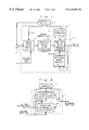
- FIG. 1 is a block diagram showing an embodiment of the present invention.
- FIG. 2 is a block diagram showing an apparatus which is used being switched between the apparatus of the present invention and the conventional apparatus.
- FIG. 3 is a flowchart for explaining the operation of the motion vector candidate selector shown in FIG. 1 .
- FIG. 4 is a diagram showing the relationship between a macroblock involved and macroblocks on the periphery thereof.
- FIG. 5 is a flowchart for explaining the operation of a predictive motion vector determinator in FIG. 1 .
- FIG. 6 is a flowchart for explaining the operation of a statistical amount measuring unit in FIG. 1 .
- FIG. 7 is a flowchart for explaining the operation of a search area determinator in FIG. 1 .
- FIG. 8 is a flowchart for explaining the operation of a predictive motion vector peripheral searcher in FIG. 1 .
- FIG. 9 is a block diagram of a second embodiment of the present invention.
- FIGS. 10A, 10 B and 10 C are graphs showing the result of experiments conducted according to the present invention.
- FIG. 11 is a block diagram showing a configuration of the conventional coding apparatus.
- FIG. 2 is a block diagram schematically showing the essential parts of the invention, which shows a configuration corresponding to the optimum motion vector searchers in the motion compensation predictor 59 and the controller 60 in FIG. 11 .
- the optimum motion vector searcher 1 is composed of an optimum motion vector searchers 2 according to the present invention, a conventional optimum motion vector searcher 3 , and a selector 4 for selecting one of the optimum motion vector searchers 2 , 3 based on the command from a controller 5 .
- the conventional optimum motion vector searcher 3 is assumed to be of a system to determine an optimum motion vector by total search, for example.
- the selector 4 switches the two searchers alternately for each macroblock.
- the relation is n-to-1 (n: positive integer)
- the optimum motion vector searcher 2 according to the present invention is selected for n macroblocks
- the conventional motion vector searcher 3 is selected for one macroblock.
- FIG. 1 is a block diagram showing a configuration of the optimum motion vector searcher 2 according to an embodiment of the present invention.
- the optimum motion vector searcher 2 is composed of a motion vector candidate selector 21 for selecting motion vector candidates based on the parameter value Prm supplied from the controller 5 , a predictive motion vector determinator 22 for determining an optimum predictive motion vector from among the motion vector candidates selected by the motion vector candidate selector 21 , and a predictive motion vector periphery searcher 23 for determining a search shape based on the distribution values VarX, VarY of the motion vectors from the statistical amount measuring unit 24 , determining the size of the search shape based on the search area supplied from a search area determinator 25 , and checking all the motion vectors within the search area having the search shape and the size described above using the optimum predictive motion vector acquired from the predictive motion vector determinator 22 as an origin of the search to determine an optimum motion vector.
- FIG. 3 is a flowchart
- FIG. 4 is a diagram for explaining a macroblock MB (hereinafter, referred to simply as the MB) to be coded and the macroblocks on the periphery thereof.
- MB macroblock MB
- step S 1 An allowable calculation amount parameter value Prm is output from the controller 5 to the motion vector candidate selector 21 .
- step S 3 it is determined that the allowable calculation amount parameter value Prm is 2
- step S 4 the motion vectors MVA, MVC and (MVA+MVC)/2 of the adjacent macroblocks MB immediately to the left and immediately above the MB are selected as reference MVs.
- step S 5 it is determined that the allowable calculation amount parameter value Prm is 3
- step S 6 the motion vectors MVA, MVC, MVD (or MVB) and (MVA+MVC+MVD or MVB)/3 of the adjacent macroblocks MB immediately to the left of, immediately above and immediately right above (or left above) the MB are selected as reference MVs.
- step S 7 it is determined that the allowable calculation amount parameter value Prm is 4
- step S 8 the motion vectors MVA, MVC, MVF, MVH and (MVA+MVC+MVF+MVH)/4 of the macroblocks shown in FIG. 4 are selected as reference MVs.
- step S 9 it is determined that the allowable calculation amount parameter value Prm is 5
- the process proceeds to step S 10 where the motion vectors MVA, MVB, MVC, MVD, MVF, MVG, MVH, MVI and an average vector thereof of the macroblocks shown in FIG. 4 are selected as reference MVs.
- step S 11 a value i is set to 0 and a predictive error threshold value Err-th is given. A sufficiently large predictive error value should be taken as the predictive error threshold value Err-th.
- step S 12 the numeral i is increased by one, and the process proceeds to step S 13 .
- step S 13 it is determined whether the relation i ⁇ imax is established, where imax is the number of the reference MVs determined by the motion vector candidate selector 21 .
- step S 13 the process proceeds to step S 14 , where the predictive error Err( 1 ) is measured at the time when the first motion vector MV( 1 ) is used. Then, the process proceeds to step S 15 , where it is determined whether the predictive error Err( 1 ) is smaller than Err-th. Generally, this determination is affirmative and the process proceeds to step S 16 . In step S 16 , the optimum motion vector is set to MV( 1 ) and the predictive error threshold value Err-th is updated to the predictive error Err( 1 ). The process then returns to step S 12 , where the value i is increased by one to be 2.
- step S 13 it is determined whether i has reached at least the number of the reference MVs. In the case that i has not reached, the process proceeds to step S 14 , the same operations are repeated. In the case that the determination in step S 15 is negative, the process returns to step S 12 .
- step S 13 determines whether the prediction in step S 13 is negative after repeating the above operations.
- step S 17 determines whether the optimum predictive motion vector MV is sent to the predictive motion vector periphery searcher 23 .
- step S 21 the value i indicating the macroblock number in the image frame is set to 0, and the motion vectors MVX, MVY in X and Y directions, respectively, are also set to 0.
- step S 22 the motion vectors MVX, MVY in X and Y directions, respectively, are also set to 0.
- step S 22 the process proceeds to step S 22 , where i is increased by one.
- step S 23 it is determined whether i ⁇ imax is established, where imax is the total number of macroblocks MB in one frame of the image.
- step S 24 the motion vectors MVX, MVY in X and Y directions, respectively, of the i-th macroblock are accumulated. Also, MVVX and MVVY are respectively determined from the equations MVVX+MVX(i) 2 and MVVY+MVY(i) 2 . This process is repeated, and in the case that the determination in step S 23 is negative, the process proceeds to step S 25 , where the average motion vector AveX in X direction, the average motion vector AveY in Y direction, the motion vector variance VarX in X direction and the motion vector variance VarY in Y direction are determined from the equations shown.
- the motion vector variances VarX, VarY in X and Y directions are sent to the predictive motion vector periphery searcher 23 .
- the allowable calculation amount parameter value Prm is output from the controller 5 to the search area determinator 25 .
- the search area determinator 25 determines, in step S 31 , whether the allowable calculation amount parameter value Prm is 1. In the case that this determination is affirmative, the process proceeds to step S 32 , where the number of pixels PN constituting the search area is set to zero. In the case that in step S 33 it is determined that the allowable calculation amount parameter value Prm is 2, the number of pixels PN constituting the search area is set to 1 to 10.
- the number of pixels PN constituting the search area is set to 11 to 30, 31 to 70 and 71 or more, respectively. These search area ranges are one example. These numbers of pixels PN constituting the search areas are sent to the predictive motion vector periphery searcher 23 .
- step S 51 it is determined whether the absolute value of the difference between the variances VarX and VarY of the motion vectors in X and Y directions of the one frame described above is equal to or less than a predetermined threshold value Th. In the case that this determination is affirmative, it is determined that the variations of the motion vectors in X and Y directions are substantially the same in X and Y directions. Therefore, the process proceeds to step S 52 , where it is determined that the peripheral search shape is a square. The shape is not limited to the square, but may be a rhombus, a polygon, a circle or the like.
- step S 53 it is determined whether the difference between the variance VarX of the motion vectors in X direction and the distribution VarY of the motion vectors in Y direction is larger than the threshold value Th. In the case that this determination is affirmative, the process proceeds to step S 54 , where it is determined that the peripheral search shape is a laterally elongate rectangle. This is because the lateral distribution of the motion vectors is considered large. On the other hand, in the case that the determination in step S 53 is negative, the process proceeds to step S 55 , where it is determined that the peripheral search shape is a longitudinally elongate rectangle. This is because the distribution of the motion vectors in longitudinal direction is considered large.
- the shape is not limited to the rectangle, but may be a laterally or vertically elongate ellipse.
- step S 56 the extent of the search is determined based on the number of pixels PN from the search area determinator 25 by using the optimum predictive motion vector MV obtained by the predictive motion vector determinator 22 as an origin.
- the peripheral search shape is a laterally elongate rectangle, if the number of pixels PN is large, the area of the rectangle is larger. This is also same as the case of other peripheral search shapes.
- step S 57 all the motion vectors MV in the peripheral search shape are checked.
- step S 58 one optimum motion vector MV is determined from all the motion vectors MV and output.
- the search shape is determined from the variance of the motion vectors, and in accordance with the magnitude of the allowable calculation amount parameter value, the search area is determined. In spite of a small calculation amount, therefore, a motion vector with high accuracy can be detected.
- This embodiment as compared with the above-described embodiment, has the characteristic in that a motion vector evaluator 26 is added to the configuration of FIG. 1 .
- the motion vector evaluator 26 determines the sum of squares of the interframe or interfield difference signal using the optimum MV determined by the predictive motion vector periphery searcher 23 , and determines whether this value is larger or smaller than a predetermined reference value.
- the controller 5 switches the selector 4 to the conventional apparatus, so that the optimum motion vector MV is again determined by the conventional method.
- the optimum motion vector MV is output as it is.
- the motion vectors with low accuracy are removed so that the reliability is improved.
- the optimum predictive motion vector is determined from among the candidate motion vectors for the portion to be coded and the search area of motion vector is determined based on the variances of the motion vectors already determined.
- the search area is searched to determine an optimum motion vector. Therefore, an optimum motion vector can be accurately obtained with a small calculation amount.
- FIGS. 10A and 10B The result of the experiments conducted by the present inventors to determine the optimum motion vector with the set one-to-one switching frequency of the selector 4 is shown in FIGS. 10A and 10B.
- the abscissa represents the number of pixels searched, and the ordinate represents the acquisition rate (%) of the optimum motion vector.
- FIG. 10A shows the case in which the Mobile & Calendar is used as an image
- FIG. 10B shows the case in which the Flower Garden is used as an image.
- characters A to E designate the motion vectors of macroblocks in the neighborhood of the macroblock in FIG. 10 C.
- Rectangle Frame shows the case in which the search shape is a rectangle
- Square Frame shows the case in which the search shape is a square.
- the probability of acquiring an optimum motion vector is equal to or more than 90% with about 25 pixels searched, and it is seen from FIG. 10B that the probability of acquiring an optimum motion vector is equal to or more than 85% with about 50 pixels.
Landscapes
- Engineering & Computer Science (AREA)
- Multimedia (AREA)
- Signal Processing (AREA)
- Physics & Mathematics (AREA)
- General Physics & Mathematics (AREA)
- Theoretical Computer Science (AREA)
- Compression Or Coding Systems Of Tv Signals (AREA)
Abstract
Description
Claims (7)
Applications Claiming Priority (2)
| Application Number | Priority Date | Filing Date | Title |
|---|---|---|---|
| JP6786198A JP3646845B2 (en) | 1998-03-03 | 1998-03-03 | Video encoding device |
| JP10-067861 | 1998-03-03 |
Publications (1)
| Publication Number | Publication Date |
|---|---|
| US6348954B1 true US6348954B1 (en) | 2002-02-19 |
Family
ID=13357152
Family Applications (1)
| Application Number | Title | Priority Date | Filing Date |
|---|---|---|---|
| US09/255,188 Expired - Fee Related US6348954B1 (en) | 1998-03-03 | 1999-02-22 | Optimum motion vector determinator and video coding apparatus using the same |
Country Status (2)
| Country | Link |
|---|---|
| US (1) | US6348954B1 (en) |
| JP (1) | JP3646845B2 (en) |
Cited By (17)
| Publication number | Priority date | Publication date | Assignee | Title |
|---|---|---|---|---|
| US20030161402A1 (en) * | 2001-12-21 | 2003-08-28 | Michael Horowitz | Motion wake identification and control mechanism |
| US6690729B2 (en) * | 1999-12-07 | 2004-02-10 | Nec Electronics Corporation | Motion vector search apparatus and method |
| US20040141555A1 (en) * | 2003-01-16 | 2004-07-22 | Rault Patrick M. | Method of motion vector prediction and system thereof |
| US20040165663A1 (en) * | 2003-01-10 | 2004-08-26 | Renesas Technology Corp. | Motion detecting device and search region variable-shaped motion detector |
| US20040264572A1 (en) * | 2003-04-28 | 2004-12-30 | Kazushi Sato | Motion prediction compensating device and its method |
| US20050100097A1 (en) * | 2003-11-10 | 2005-05-12 | Samsung Electronics Co., Ltd. | Apparatus and method for motion vector prediction |
| US20070127575A1 (en) * | 2003-11-11 | 2007-06-07 | Cheng-Tsai Ho | Method and related apparatus for motion estimation |
| US20070133681A1 (en) * | 2003-11-11 | 2007-06-14 | Cheng-Tsai Ho | Method and related apparatus for motion estimation |
| US20090021637A1 (en) * | 2007-07-18 | 2009-01-22 | Sony Corporation | Image processing device, image processing method, program, and display device |
| US20090060373A1 (en) * | 2007-08-24 | 2009-03-05 | General Electric Company | Methods and computer readable medium for displaying a restored image |
| US20100034274A1 (en) * | 2004-10-14 | 2010-02-11 | Eric Li | Fast multi-frame motion estimation with adaptive search strategies |
| US20110001882A1 (en) * | 2009-07-06 | 2011-01-06 | Sony Corporation | Method and system for determining motion vectors for flat regions |
| US20120128073A1 (en) * | 2009-06-18 | 2012-05-24 | Asaka Saori | Video encoding apparatus and a video decoding apparatus |
| WO2012097753A1 (en) * | 2011-01-22 | 2012-07-26 | 华为技术有限公司 | Motion prediction or compensation method |
| US20150381900A1 (en) * | 2014-06-30 | 2015-12-31 | Casio Computer Co., Ltd | Electronic device, information control method, and non-transitory computer-readable recording medium |
| US9628794B2 (en) | 2009-06-18 | 2017-04-18 | Kabushiki Kaisha Toshiba | Video encoding apparatus and a video decoding apparatus |
| US11051715B2 (en) * | 2016-02-15 | 2021-07-06 | Samsung Electronics Co., Ltd. | Image processing apparatus, image processing method, and recording medium recording same |
Families Citing this family (3)
| Publication number | Priority date | Publication date | Assignee | Title |
|---|---|---|---|---|
| JP4252916B2 (en) | 2004-03-18 | 2009-04-08 | 富士通マイクロエレクトロニクス株式会社 | Method for determining motion vector search range |
| JP6665611B2 (en) | 2016-03-18 | 2020-03-13 | 富士通株式会社 | Encoding processing program, encoding processing method, and encoding processing device |
| CN110662074B (en) * | 2018-06-28 | 2021-11-23 | 杭州海康威视数字技术股份有限公司 | Motion vector determination method and device |
Citations (2)
| Publication number | Priority date | Publication date | Assignee | Title |
|---|---|---|---|---|
| JPS63181585A (en) | 1987-01-23 | 1988-07-26 | Hitachi Ltd | Motion compensated interframe coding device for TV signals |
| US6249550B1 (en) * | 1996-09-20 | 2001-06-19 | Nec Corporation | Motion vector estimating apparatus with high speed and method of estimating motion vector |
-
1998
- 1998-03-03 JP JP6786198A patent/JP3646845B2/en not_active Expired - Fee Related
-
1999
- 1999-02-22 US US09/255,188 patent/US6348954B1/en not_active Expired - Fee Related
Patent Citations (2)
| Publication number | Priority date | Publication date | Assignee | Title |
|---|---|---|---|---|
| JPS63181585A (en) | 1987-01-23 | 1988-07-26 | Hitachi Ltd | Motion compensated interframe coding device for TV signals |
| US6249550B1 (en) * | 1996-09-20 | 2001-06-19 | Nec Corporation | Motion vector estimating apparatus with high speed and method of estimating motion vector |
Cited By (41)
| Publication number | Priority date | Publication date | Assignee | Title |
|---|---|---|---|---|
| US6690729B2 (en) * | 1999-12-07 | 2004-02-10 | Nec Electronics Corporation | Motion vector search apparatus and method |
| US8780970B2 (en) * | 2001-12-21 | 2014-07-15 | Polycom, Inc. | Motion wake identification and control mechanism |
| US20030161402A1 (en) * | 2001-12-21 | 2003-08-28 | Michael Horowitz | Motion wake identification and control mechanism |
| US20070127830A1 (en) * | 2003-01-10 | 2007-06-07 | Renesas Technology Corp. | Motion detecting device and search region variable-shaped motion detector |
| US20040165663A1 (en) * | 2003-01-10 | 2004-08-26 | Renesas Technology Corp. | Motion detecting device and search region variable-shaped motion detector |
| US8019168B2 (en) | 2003-01-10 | 2011-09-13 | Renesas Electronics Corporation | Motion detecting device and search region variable-shaped motion detector |
| US7187803B2 (en) * | 2003-01-10 | 2007-03-06 | Renesas Technology Corp. | Motion detecting device and search region variable-shaped motion detector |
| US20040141555A1 (en) * | 2003-01-16 | 2004-07-22 | Rault Patrick M. | Method of motion vector prediction and system thereof |
| US20040264572A1 (en) * | 2003-04-28 | 2004-12-30 | Kazushi Sato | Motion prediction compensating device and its method |
| US7746930B2 (en) * | 2003-04-28 | 2010-06-29 | Sony Corporation | Motion prediction compensating device and its method |
| US20050100097A1 (en) * | 2003-11-10 | 2005-05-12 | Samsung Electronics Co., Ltd. | Apparatus and method for motion vector prediction |
| US8170104B2 (en) * | 2003-11-10 | 2012-05-01 | Samsung Electronics Co., Ltd. | Apparatus and method for motion vector prediction |
| US20070133681A1 (en) * | 2003-11-11 | 2007-06-14 | Cheng-Tsai Ho | Method and related apparatus for motion estimation |
| US20070127575A1 (en) * | 2003-11-11 | 2007-06-07 | Cheng-Tsai Ho | Method and related apparatus for motion estimation |
| US20100034274A1 (en) * | 2004-10-14 | 2010-02-11 | Eric Li | Fast multi-frame motion estimation with adaptive search strategies |
| US8879633B2 (en) | 2004-10-14 | 2014-11-04 | Intel Corporation | Fast multi-frame motion estimation with adaptive search strategies |
| US8619855B2 (en) | 2004-10-14 | 2013-12-31 | Intel Corporation | Fast multi-frame motion estimation with adaptive search strategies |
| US20090021637A1 (en) * | 2007-07-18 | 2009-01-22 | Sony Corporation | Image processing device, image processing method, program, and display device |
| US20090060373A1 (en) * | 2007-08-24 | 2009-03-05 | General Electric Company | Methods and computer readable medium for displaying a restored image |
| US9602815B2 (en) | 2009-06-18 | 2017-03-21 | Kabushiki Kaisha Toshiba | Video encoding apparatus and video decoding apparatus |
| US9167273B2 (en) * | 2009-06-18 | 2015-10-20 | Kabushiki Kaisha Toshiba | Video encoding apparatus and a video decoding apparatus |
| US12587671B2 (en) | 2009-06-18 | 2026-03-24 | Kabushiki Kaisha Toshiba | Video encoding apparatus and a video decoding apparatus |
| US20140177727A1 (en) * | 2009-06-18 | 2014-06-26 | Kabushiki Kaisha Toshiba | Video encoding apparatus and video decoding apparatus |
| US20120128073A1 (en) * | 2009-06-18 | 2012-05-24 | Asaka Saori | Video encoding apparatus and a video decoding apparatus |
| US12120339B2 (en) | 2009-06-18 | 2024-10-15 | Kabushiki Kaisha Toshiba | Video encoding apparatus and a video decoding apparatus |
| US11729413B2 (en) | 2009-06-18 | 2023-08-15 | Kabushiki Kaisha Toshiba | Video encoding apparatus and a video decoding apparatus |
| US10341676B2 (en) | 2009-06-18 | 2019-07-02 | Kabushiki Kaisha Toshiba | Video encoding apparatus and a video decoding apparatus |
| US11265571B2 (en) | 2009-06-18 | 2022-03-01 | Kabushiki Kaisha Toshiba | Video encoding apparatus and a video decoding apparatus |
| US10939133B2 (en) | 2009-06-18 | 2021-03-02 | Kabushiki Kaisha Toshiba | Video encoding apparatus and a video decoding apparatus |
| US9307242B2 (en) * | 2009-06-18 | 2016-04-05 | Kabushiki Kaisha Toshiba | Video encoding apparatus and video decoding apparatus |
| US10880568B2 (en) | 2009-06-18 | 2020-12-29 | Kabushiki Kaisha Toshiba | Video encoding apparatus and a video decoding apparatus |
| US9628794B2 (en) | 2009-06-18 | 2017-04-18 | Kabushiki Kaisha Toshiba | Video encoding apparatus and a video decoding apparatus |
| US9979980B2 (en) | 2009-06-18 | 2018-05-22 | Kabushiki Kaisha Toshiba | Video encoding apparatus and a video decoding apparatus |
| US20110001882A1 (en) * | 2009-07-06 | 2011-01-06 | Sony Corporation | Method and system for determining motion vectors for flat regions |
| CN101945209A (en) * | 2009-07-06 | 2011-01-12 | 索尼公司 | The method and system that is used for the motion vector of definite flat site |
| CN102710934A (en) * | 2011-01-22 | 2012-10-03 | 华为技术有限公司 | Motion predicting or compensating method |
| US9288492B2 (en) | 2011-01-22 | 2016-03-15 | Huawei Technologies Co., Ltd. | Motion prediction or compensation method |
| CN102710934B (en) * | 2011-01-22 | 2015-05-06 | 华为技术有限公司 | Motion predicting or compensating method |
| WO2012097753A1 (en) * | 2011-01-22 | 2012-07-26 | 华为技术有限公司 | Motion prediction or compensation method |
| US20150381900A1 (en) * | 2014-06-30 | 2015-12-31 | Casio Computer Co., Ltd | Electronic device, information control method, and non-transitory computer-readable recording medium |
| US11051715B2 (en) * | 2016-02-15 | 2021-07-06 | Samsung Electronics Co., Ltd. | Image processing apparatus, image processing method, and recording medium recording same |
Also Published As
| Publication number | Publication date |
|---|---|
| JPH11252571A (en) | 1999-09-17 |
| JP3646845B2 (en) | 2005-05-11 |
Similar Documents
| Publication | Publication Date | Title |
|---|---|---|
| US6348954B1 (en) | Optimum motion vector determinator and video coding apparatus using the same | |
| RU2703957C1 (en) | Predictive video coding device, predictive video coding method, prediction video coding software, prediction video decoding device, prediction video decoding method and prediction video decoding software | |
| RU2381630C2 (en) | Method and device for determining block conformity quality | |
| KR100492127B1 (en) | Apparatus and method of adaptive motion estimation | |
| US6925123B2 (en) | Method and apparatus for performing high quality fast predictive motion search | |
| US6549576B1 (en) | Motion vector detecting method and apparatus | |
| US5650829A (en) | Motion video coding systems with motion vector detection | |
| KR0171146B1 (en) | Motion vector detection device using feature points | |
| JP5044568B2 (en) | Motion estimation using predictive guided decimation search | |
| KR950009699B1 (en) | Motion vector detection method and apparatus | |
| EP0609022A2 (en) | Image encoding apparatus | |
| KR20020028625A (en) | Method and apparatus for motion estimation of hybrid type | |
| JP2003528500A (en) | Motion estimation algorithm | |
| WO2010035370A1 (en) | Dynamic image encoding method and dynamic image decoding method | |
| CN100481952C (en) | Method and apparatus for determining search range of adaptive motion vector in video encoder | |
| KR100994768B1 (en) | Motion Estimation Method for Motion Picture Coding and Recording Media with Program for Implementing It | |
| US20060203912A1 (en) | Motion vector detection method, motion vector detection apparatus, computer program for executing motion vector detection process on computer | |
| US20050074064A1 (en) | Method for hierarchical motion estimation | |
| JP2005101811A (en) | Motion vector detection device | |
| KR100782800B1 (en) | Motion estimation method | |
| US20020168008A1 (en) | Method and apparatus for coding moving pictures | |
| US20080130749A1 (en) | Method for Performing Pattern-Based Block Motion Estimation | |
| JP2002539685A (en) | Block matching motion estimation | |
| US20080137746A1 (en) | Method for Predicting Performance of Patterns Used in Block Motion Estimation Procedures | |
| US20070274390A1 (en) | System for Performing Pattern-Based Block Motion Estimation |
Legal Events
| Date | Code | Title | Description |
|---|---|---|---|
| AS | Assignment |
Owner name: KDD CORPORATION, JAPAN Free format text: ASSIGNMENT OF ASSIGNORS INTEREST;ASSIGNORS:TAKISHIMA, YASUHIRO;SAKAZAWA, SHIGEYUKI;WADA, MASAHIRO;REEL/FRAME:009786/0181 Effective date: 19990212 |
|
| FEPP | Fee payment procedure |
Free format text: PAYOR NUMBER ASSIGNED (ORIGINAL EVENT CODE: ASPN); ENTITY STATUS OF PATENT OWNER: LARGE ENTITY |
|
| AS | Assignment |
Owner name: DDI CORPORATION, JAPAN Free format text: MERGER;ASSIGNOR:KDD CORPORATION;REEL/FRAME:013957/0664 Effective date: 20001001 |
|
| AS | Assignment |
Owner name: KDDI CORPORATION, JAPAN Free format text: CHANGE OF NAME;ASSIGNOR:DDI CORPORATION;REEL/FRAME:014083/0804 Effective date: 20010401 |
|
| FPAY | Fee payment |
Year of fee payment: 4 |
|
| FPAY | Fee payment |
Year of fee payment: 8 |
|
| REMI | Maintenance fee reminder mailed | ||
| LAPS | Lapse for failure to pay maintenance fees | ||
| STCH | Information on status: patent discontinuation |
Free format text: PATENT EXPIRED DUE TO NONPAYMENT OF MAINTENANCE FEES UNDER 37 CFR 1.362 |
|
| FP | Lapsed due to failure to pay maintenance fee |
Effective date: 20140219 |