US634857A - Bicycle-whirl. - Google Patents
Bicycle-whirl. Download PDFInfo
- Publication number
- US634857A US634857A US71972898A US1898719728A US634857A US 634857 A US634857 A US 634857A US 71972898 A US71972898 A US 71972898A US 1898719728 A US1898719728 A US 1898719728A US 634857 A US634857 A US 634857A
- Authority
- US
- United States
- Prior art keywords
- bicycle
- whirl
- yoke
- frame
- bicycles
- Prior art date
- Legal status (The legal status is an assumption and is not a legal conclusion. Google has not performed a legal analysis and makes no representation as to the accuracy of the status listed.)
- Expired - Lifetime
Links
Images

Classifications
-
- A—HUMAN NECESSITIES
- A63—SPORTS; GAMES; AMUSEMENTS
- A63G—MERRY-GO-ROUNDS; SWINGS; ROCKING-HORSES; CHUTES; SWITCHBACKS; SIMILAR DEVICES FOR PUBLIC AMUSEMENT
- A63G1/00—Roundabouts
- A63G1/22—Roundabouts with bicycles serving as seats
Definitions
- My present in vention relates to an improvement in bicycle-whirls, and has for its object the production of a whirl giving certain capabilities of independent movement to the individual bicycles adapted to be propelled by the riders, which is more agreeable to the riders, more perfect in construction, and capable of nicer adjustment and of greater durability than machines of this character heretofore in use.
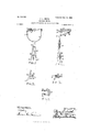
- Figure 1 is a plan view of a portion of my bicycle whirl.
- Fig. 2 is a side elevation showing one of the bicycles in side and one in front elevation, the intervening wheels being omitted for the sake of clearness.
- Fig. 3 is a plan view of a bicycle-supporting yoke, showing its connection with the guy-rods and a bicy-
- Fig. 4t is a front elevation of the same.
- Fig. 5 is a side elevation of the frontfork yoke shown as attached to the fork and lower chord of the bicycle-frame.
- Fig. 6 is a plan view of the same, and
- Fig. 7 is a detail plan View of the front-fork yoke.
- A indicates a center post, upon which in any suitable manner is rotatably mounted the whirl-ring B, to the outer periphery of which are attached the guy-rods 0, extended outwardly in pairs to bicycle-yoke bearings D, rigidly mounted thereon.
- E indicates the bicycle-yoke which, as shown, is provided with a radial shaft F, which is rotatably supported in the bearings D, before referred to, being held in place by a collar G on its end.
- Bicycles of ordinary construction and Without alteration are arranged in a circle around the above-described supporting-frame, each being supported by one of the yokes in any suitable or desired manner, the preferred form being described as follows:
- the head-clamp II which is provided on one side with the ear I.
- the seat-post clamp J which is provided with a rearwardly-projected ear which passesout between the rear forks of the frame and is then turned to one side.
- To these tWo ears I and J are pivotally attached the two arms of the bicycle-yoke E.
- a brace K connects the rear arm of the bicycle-yoke with the axle of the rear wheel, being pivotally attached to the arm of a clamp L and to the axle by a plate M. It will be observed that the guyrods 0 are attached to the whirl-ring B in pairs, one pair running from the top of the ring to one bicycle and the next pair running from the bottom of the ring to the next bicycle, thus necessitating the capability of angular adjustment of the yokes to the bicycles.
- a front-fork yoke N provided with clamps O O on the end of its two arms adapted to be fixedly secured to the arms of the front fork.
- the rear end of the frontfork yoke N is provided with a slot P, out in the arc of a circle, of which the center is the center line of the bicycle-head.
- the clamp Q Fixedly secured to the lower chord of the bicycleframe is the clamp Q, which is provided on its under side with a bolt R, which extends down through the slot P, and by the screwing up of which the front-fork yoke N may be secured in the proper position to hold the front wheel at the proper angle to make the bicycle run smoothly in the circular path required by any given diameter of bicycle-whirl.
- a baby or child seat S is or may be supported on the guy-rods over the yoke-shaft bearings.
- spring connections T may be interposed between the successive pairs of guy-rods.
- the whirl is especially adapted to be propelled by-the bicycle-riders themselves, or, if preferred, it maybe driven from the whirlwheel B in any usual or suitable manner.
- a rotatably-supported frame, of a bicycle and a bicycle-yoke carried by said frame havingtwo arms adapted to be attached, respectively, to the head and seat-post of said bicycle and a brace extended from the reararrn to the axle of the rear wheel of said bicycle, substantially as described.
Landscapes
- Steering Devices For Bicycles And Motorcycles (AREA)
Description
P. L. SMITH.
BICYCLE WHIRL.
(Application filed Sept. 14, 1898. Banawed June 7, 1899.)
(No Model.) 2 Shets-Shet l.
WITNESSES INVENT UR- Patented-Oct. l0, I899. k
No. 634,857. Patented Oct. I0, 1899. P. L. SMITH.
BICYCLE WHIRL.
(Application filed Sept. 14, 1898. Bnnewed June 7, 189 9.)
2 Sheets-Sheet 2,
(No Model.)
' INVENTUR WITNESSES an: 00.. morou'rna. WASH ole-frame.
PERCY L. SMITH, OF LOIVELL, MASSACHUSETTS.
BICYCLE-WHIRL.
SPECIFICATION forming part of Letters Patent No. 634,857, dated October 10, 1899. Application filed September 14, 1898. Renewed June '7, 1899. Serial No. 719,728. (No modeLl T0 aZZ whom, it may concern:
Be it known that I, PERCY L. SMrrI-I, a citizen of the United States, residing at Lowell, in the county of Middlesex and State of Massachusetts, have invented certain new and useful Improvements in Bicyclehirds; and I do hereby declare the following to be a full clear, and exact description of the invention, such as will enable others skilled in the art to which itappertains to make and use the same.
My present in vention relates to an improvement in bicycle-whirls, and has for its object the production of a whirl giving certain capabilities of independent movement to the individual bicycles adapted to be propelled by the riders, which is more agreeable to the riders, more perfect in construction, and capable of nicer adjustment and of greater durability than machines of this character heretofore in use.
My invention consists in the machine herei'nafter described, and particularly pointed out in the claims at the end of this specification.
In the accompanying drawings,illustrating the preferred form of my invention, Figure 1 is a plan view of a portion of my bicycle whirl. Fig. 2 is a side elevation showing one of the bicycles in side and one in front elevation, the intervening wheels being omitted for the sake of clearness. Fig. 3 is a plan view of a bicycle-supporting yoke, showing its connection with the guy-rods and a bicy- Fig. 4t is a front elevation of the same. Fig. 5 is a side elevation of the frontfork yoke shown as attached to the fork and lower chord of the bicycle-frame. Fig. 6 is a plan view of the same, and Fig. 7 is a detail plan View of the front-fork yoke.
A indicates a center post, upon which in any suitable manner is rotatably mounted the whirl-ring B, to the outer periphery of which are attached the guy-rods 0, extended outwardly in pairs to bicycle-yoke bearings D, rigidly mounted thereon.
E indicates the bicycle-yoke which, as shown, is provided with a radial shaft F, which is rotatably supported in the bearings D, before referred to, being held in place by a collar G on its end.
Bicycles of ordinary construction and Without alteration are arranged in a circle around the above-described supporting-frame, each being supported by one of the yokes in any suitable or desired manner, the preferred form being described as follows: Upon the head of the bicycle-frame is securely fixed the head-clamp II, which is provided on one side with the ear I. Similarly fixed upon the seat-post of the bicycle-frame is the seat-post clamp J, which is provided with a rearwardly-projected ear which passesout between the rear forks of the frame and is then turned to one side. To these tWo ears I and J are pivotally attached the two arms of the bicycle-yoke E. A brace K connects the rear arm of the bicycle-yoke with the axle of the rear wheel, being pivotally attached to the arm of a clamp L and to the axle by a plate M. It will be observed that the guyrods 0 are attached to the whirl-ring B in pairs, one pair running from the top of the ring to one bicycle and the next pair running from the bottom of the ring to the next bicycle, thus necessitating the capability of angular adjustment of the yokes to the bicycles. In Fig. 4 there is shown in full lines the position of the guy-rods, yoke, and brace when the guy-rods run from the bottom of the whirl-ring and in dotted lines the positions of the parts when the'guy-rods run from the top of the whirl-ring, and it is seen that the clamp L in the latter case is slightly nearer the bicycle to compensate for the difference in inclination of the guy-rods. Thus it is seen that the bicycle-frame is supported in a vertical plane, but permitted to move vertically and oscillate in said plane about the yoke-shaft F as a center to compensate for accidental or intended inequalities or curvatures of the floor over which the bicycles run.
In order that the bicycles may run properly in the predetermined circular path, I have provided means for setting and holding the front fork in its proper position, and for this purpose I have made a front-fork yoke N, provided with clamps O O on the end of its two arms adapted to be fixedly secured to the arms of the front fork. The rear end of the frontfork yoke N is provided with a slot P, out in the arc of a circle, of which the center is the center line of the bicycle-head. Fixedly secured to the lower chord of the bicycleframe is the clamp Q, which is provided on its under side with a bolt R, which extends down through the slot P, and by the screwing up of which the front-fork yoke N may be secured in the proper position to hold the front wheel at the proper angle to make the bicycle run smoothly in the circular path required by any given diameter of bicycle-whirl.
A baby or child seat S is or may be supported on the guy-rods over the yoke-shaft bearings.
If desirable, spring connections T may be interposed between the successive pairs of guy-rods.
The whirl is especially adapted to be propelled by-the bicycle-riders themselves, or, if preferred, it maybe driven from the whirlwheel B in any usual or suitable manner.
Having thus described my invention, I claim as new and desire to secure by Letters Patent of the United States- 1. In a bicycle-whirl, the combination with a center post, of a plurality of bicycles, and means for supporting said bicycles in a circle around said post consisting of a frame rotatably mounted on said post and carrying at its periphery radial bearings and bicycleyokes supporting the bicycles and provided, respectively, with radial shafts supported in said bearings, each yoke having two arms ats 3. In a bicycle-whirl, the combination with.
a rotatably-supported frame, of a bicycle and a bicycle-yoke carried by said frame, havingtwo arms adapted to be attached, respectively, to the head and seat-post of said bicycle and a brace extended from the reararrn to the axle of the rear wheel of said bicycle, substantially as described.
-'.l. The combination with a rotatably-supported frame, of a bicycle and a bicycle-yoke attached rigidly to the head and seat-post of said bicycle, and radially pivoted to said frame, substantially as described.
In testimony whereof I affix my signature in presence of two witnesses.
PERCY L. SMITH.
Witnesses:
THOMAS C. RUTLAND, HORACE VAN EVERNS.
Priority Applications (1)
| Application Number | Priority Date | Filing Date | Title |
|---|---|---|---|
| US71972898A US634857A (en) | 1898-09-14 | 1898-09-14 | Bicycle-whirl. |
Applications Claiming Priority (1)
| Application Number | Priority Date | Filing Date | Title |
|---|---|---|---|
| US71972898A US634857A (en) | 1898-09-14 | 1898-09-14 | Bicycle-whirl. |
Publications (1)
| Publication Number | Publication Date |
|---|---|
| US634857A true US634857A (en) | 1899-10-10 |
Family
ID=2703448
Family Applications (1)
| Application Number | Title | Priority Date | Filing Date |
|---|---|---|---|
| US71972898A Expired - Lifetime US634857A (en) | 1898-09-14 | 1898-09-14 | Bicycle-whirl. |
Country Status (1)
| Country | Link |
|---|---|
| US (1) | US634857A (en) |
-
1898
- 1898-09-14 US US71972898A patent/US634857A/en not_active Expired - Lifetime
Similar Documents
| Publication | Publication Date | Title |
|---|---|---|
| US634857A (en) | Bicycle-whirl. | |
| US521786A (en) | Monocycle | |
| US1165467A (en) | Motor attachment for bicycles. | |
| US415740A (en) | sharp | |
| US424870A (en) | Bicycle | |
| US448358A (en) | Tandem bicycle | |
| US669201A (en) | Bicycle. | |
| US628426A (en) | Bicycle. | |
| US616665A (en) | hartzell | |
| US381763A (en) | Tricycle | |
| US402313A (en) | duryea | |
| US645474A (en) | Bicycle. | |
| US95521A (en) | Improved sleigh-attachment for velocipedes | |
| US443818A (en) | Velocipede | |
| US833651A (en) | Motor and other cycle. | |
| US1261441A (en) | Spring suspension for motor or other cycles. | |
| US583078A (en) | Frederick d | |
| US602552A (en) | Island | |
| US186379A (en) | Improvement in velocipedes | |
| US1334727A (en) | Pleasure-machine | |
| US93433A (en) | Improvement in velocipedes | |
| US91535A (en) | Improvement in velocipede | |
| US641193A (en) | Bicycle. | |
| US605214A (en) | Half to frank l | |
| US510167A (en) | George richard fenner |