US6340210B1 - Wheel for vehicle - Google Patents
Wheel for vehicle Download PDFInfo
- Publication number
- US6340210B1 US6340210B1 US09/517,768 US51776800A US6340210B1 US 6340210 B1 US6340210 B1 US 6340210B1 US 51776800 A US51776800 A US 51776800A US 6340210 B1 US6340210 B1 US 6340210B1
- Authority
- US
- United States
- Prior art keywords
- wheel
- vehicle
- center plate
- disk
- hub
- Prior art date
- Legal status (The legal status is an assumption and is not a legal conclusion. Google has not performed a legal analysis and makes no representation as to the accuracy of the status listed.)
- Expired - Lifetime
Links
Images


Classifications
-
- B—PERFORMING OPERATIONS; TRANSPORTING
- B60—VEHICLES IN GENERAL
- B60B—VEHICLE WHEELS; CASTORS; AXLES FOR WHEELS OR CASTORS; INCREASING WHEEL ADHESION
- B60B3/00—Disc wheels, i.e. wheels with load-supporting disc body
- B60B3/002—Disc wheels, i.e. wheels with load-supporting disc body characterised by the shape of the disc
-
- B—PERFORMING OPERATIONS; TRANSPORTING
- B60—VEHICLES IN GENERAL
- B60B—VEHICLE WHEELS; CASTORS; AXLES FOR WHEELS OR CASTORS; INCREASING WHEEL ADHESION
- B60B21/00—Rims
- B60B21/10—Rims characterised by the form of tyre-seat or flange, e.g. corrugated
- B60B21/104—Rims characterised by the form of tyre-seat or flange, e.g. corrugated the shape of flanges
-
- B—PERFORMING OPERATIONS; TRANSPORTING
- B60—VEHICLES IN GENERAL
- B60B—VEHICLE WHEELS; CASTORS; AXLES FOR WHEELS OR CASTORS; INCREASING WHEEL ADHESION
- B60B25/00—Rims built-up of several main parts ; Locking means for the rim parts
- B60B25/002—Rims split in circumferential direction
-
- B—PERFORMING OPERATIONS; TRANSPORTING
- B60—VEHICLES IN GENERAL
- B60B—VEHICLE WHEELS; CASTORS; AXLES FOR WHEELS OR CASTORS; INCREASING WHEEL ADHESION
- B60B27/00—Hubs
-
- B—PERFORMING OPERATIONS; TRANSPORTING
- B60—VEHICLES IN GENERAL
- B60B—VEHICLE WHEELS; CASTORS; AXLES FOR WHEELS OR CASTORS; INCREASING WHEEL ADHESION
- B60B27/00—Hubs
- B60B27/0005—Hubs with ball bearings
-
- B—PERFORMING OPERATIONS; TRANSPORTING
- B60—VEHICLES IN GENERAL
- B60B—VEHICLE WHEELS; CASTORS; AXLES FOR WHEELS OR CASTORS; INCREASING WHEEL ADHESION
- B60B27/00—Hubs
- B60B27/06—Hubs adapted to be fixed on axle
-
- B—PERFORMING OPERATIONS; TRANSPORTING
- B60—VEHICLES IN GENERAL
- B60B—VEHICLE WHEELS; CASTORS; AXLES FOR WHEELS OR CASTORS; INCREASING WHEEL ADHESION
- B60B3/00—Disc wheels, i.e. wheels with load-supporting disc body
- B60B3/08—Disc wheels, i.e. wheels with load-supporting disc body with disc body formed by two or more axially spaced discs
-
- B—PERFORMING OPERATIONS; TRANSPORTING
- B60—VEHICLES IN GENERAL
- B60B—VEHICLE WHEELS; CASTORS; AXLES FOR WHEELS OR CASTORS; INCREASING WHEEL ADHESION
- B60B3/00—Disc wheels, i.e. wheels with load-supporting disc body
- B60B3/10—Disc wheels, i.e. wheels with load-supporting disc body apertured to simulate spoked wheels
-
- B—PERFORMING OPERATIONS; TRANSPORTING
- B60—VEHICLES IN GENERAL
- B60B—VEHICLE WHEELS; CASTORS; AXLES FOR WHEELS OR CASTORS; INCREASING WHEEL ADHESION
- B60B3/00—Disc wheels, i.e. wheels with load-supporting disc body
- B60B3/14—Attaching disc body to hub ; Wheel adapters
- B60B3/145—Attaching disc body to hub ; Wheel adapters using washers or distance bushes
-
- B—PERFORMING OPERATIONS; TRANSPORTING
- B60—VEHICLES IN GENERAL
- B60B—VEHICLE WHEELS; CASTORS; AXLES FOR WHEELS OR CASTORS; INCREASING WHEEL ADHESION
- B60B7/00—Wheel cover discs, rings, or the like, for ornamenting, protecting, venting, or obscuring, wholly or in part, the wheel body, rim, hub, or tyre sidewall, e.g. wheel cover discs, wheel cover discs with cooling fins
- B60B7/0013—Hub caps
-
- B—PERFORMING OPERATIONS; TRANSPORTING
- B60—VEHICLES IN GENERAL
- B60B—VEHICLE WHEELS; CASTORS; AXLES FOR WHEELS OR CASTORS; INCREASING WHEEL ADHESION
- B60B7/00—Wheel cover discs, rings, or the like, for ornamenting, protecting, venting, or obscuring, wholly or in part, the wheel body, rim, hub, or tyre sidewall, e.g. wheel cover discs, wheel cover discs with cooling fins
- B60B7/02—Wheel cover discs, rings, or the like, for ornamenting, protecting, venting, or obscuring, wholly or in part, the wheel body, rim, hub, or tyre sidewall, e.g. wheel cover discs, wheel cover discs with cooling fins made essentially in one part
-
- B—PERFORMING OPERATIONS; TRANSPORTING
- B60—VEHICLES IN GENERAL
- B60B—VEHICLE WHEELS; CASTORS; AXLES FOR WHEELS OR CASTORS; INCREASING WHEEL ADHESION
- B60B7/00—Wheel cover discs, rings, or the like, for ornamenting, protecting, venting, or obscuring, wholly or in part, the wheel body, rim, hub, or tyre sidewall, e.g. wheel cover discs, wheel cover discs with cooling fins
- B60B7/06—Fastening arrangements therefor
- B60B7/061—Fastening arrangements therefor characterised by the part of the wheels to which the discs, rings or the like are mounted
- B60B7/065—Fastening arrangements therefor characterised by the part of the wheels to which the discs, rings or the like are mounted to the disc
Definitions
- the present invention relates generally to a wheel for a vehicle and, more particularly, to a vehicular wheel which allows improvement of an external appearance thereof.
- split rim wheels for vehicles have been known. These wheels comprise two wheel halves joined together, each wheel half being cup-shaped and having a disk portion forming a bottom thereof and a rim portion forming a peripheral wall thereof.
- Typical examples of such split rim wheels are disclosed in, for example, Japanese Utility Model Laid-Open Publication No. SHO-62-2401 entitled “Composite Wheel of Light Alloy” and Japanese Patent Laid-Open Publication No. HEI-11-245602 entitled “Wheel for Vehicle”.
- the wheel disclosed in Japanese Utility Model Laid-Open Publication No. SHO-62-2401 comprises two cup-shaped wheel members each having a flange at a bottom thereof, and a connector plate interposed between the flanges. An outer periphery of the connector plate is weld-connected to each wheel member, whereby the wheel members and the connector plate are unitarily connected together to provide the wheel.
- the wheel disclosed in Japanese Patent Laid-Open Publication No. HEI-11-245602 comprises cup-shaped outer and inner rims, and an insert plate interposed between the rims.
- the outer rim and inner rim are weld-connected together with the insert plate sandwiched therebetween to thereby provide the unitarily formed wheel.
- each of the flanges and connector plate is in a simple flat-plate form. This does not meet the diversified needs and liking of users. Wheels wherein flanges are designed to have curved planes and irregularities as found in a single-piece flange of a conventional steel wheel are more favored now.
- a wheel for a vehicle which comprises: first and second wheel halves joined together, each of the wheel halves having a disk portion and a rim continuing from the disk portion; a center plate inter-posed between the disk portions of the wheel halves, the center plate being generally cross-shaped and having a diameter smaller than an outside diameter of each of the disk portions; and the first wheel half, the second wheel half and the center plate being unitarily connected together by means of a plurality of sockets each having a countersunk head and a cylindrical shank.
- center plate being cross-shaped, it becomes possible to make the wheel light in weight compared to where the center plate is in the form of a circular plate.
- those portions of the first and second wheel halves which are not opposed to four projections of the cross-shaped center plate become dual-structured, it becomes posible to provide those portions with recesses, inclined surfaces and windows which impart an improved external appearance to the wheel.
- the first and second wheel halves are connected together by a weld which is offset from the center plate in a direction toward that one of the first and second wheel halves which is positioned closer to the vehicle when the wheel is mounted to the vehicle.
- a weld which is offset from the center plate in a direction toward that one of the first and second wheel halves which is positioned closer to the vehicle when the wheel is mounted to the vehicle.
- the rim of the one wheel half positioned closer to the vehicle has a flange at a top end thereof and that the flange has a flank formed on a side surface thereof so that a clearance is defined between the flange and a tie rod, connected to a knuckle provided in the wheel, when the tie rod is brought to a position closest to the one wheel half by turning a handlebar of the vehicle.
- a wheel for a vehicle which comprises: first and second wheel halves joined together, each of the wheel halves having a disk portion and a rim continuing from the disk portion; a center plate inter-posed between the disk portions of the wheel halves, the center plate having a diameter smaller than an outside diameter of each of the disk portions; the first wheel half, the second wheel half and the center plate being unitarily connected together by means of a plurality of sockets each having a countersunk head and a cylindrical shank; and the second wheel halt being positioned closer to the vehicle when the wheel is mounted to a hub which in turn is connected to an axle of the vehicle, the disk portion of the second wheel half having recesses at portions thereof opposed to a peripheral edge of the hub.
- At least one of the disk portions has a discharge hole for discharging water and a wheel surface treating liquid accumulated between the disk portions.
- the center plate has a hole formed centerally thereof while the disk portion of the second wheel half has a centrally-formed hole larger than the hole of the center plate.
- FIG. 1 is a perspective view illustrating a vehicle having wheels according to the present invention
- FIG. 2 is an enlarged front elevational view illustrating one of the wheels according to the present invention
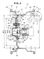
- FIG. 3 is a cross-sectional view taken along line 3 — 3 of FIG. 2;
- FIG. 4 is an exploded perspective view illustrating one of the wheels according to the present invention.
- FIG. 5 is an enlarged partial sectional view illustrating outer and inner wheel halves shown in FIG. 3, with some of their parts omitted for clarity;
- FIG. 6 is a rear view of the wheel, illustrative of the shape of the inner wheel half
- FIG. 7A is an enlarged partial sectional view illustrating the front wheel as attached to a hub
- FIG. 7B is an enlarged partial sectional view similar to FIG. 7A but illustrating one of the rear wheels as attached to the hub;
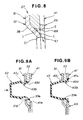
- FIG. 8 is a view illustrating a function of notches provided in the front wheel half.
- FIGS. 9A and 9B are enlarged partial sectional views illustrating a manner of attachment of a center cap to the wheel.
- the motorized buggy 10 comprises a handlebar 12 rotatably mounted to a vehicle body or chassis 11 , front wheel assemblies 13 , 13 steerably connected to the handlebar 12 via a steering gear device (not shown), a driver seat 14 mounted on an upper part of the vehicle body 11 , a power unit 15 comprised of an engine and a transmission disposed under the seat 14 , and rear wheel assemblies 16 , 16 driven by the power unit 15 .
- Reference numeral 17 designates a bumper; 18 is a front suspension unit; 21 is a headlamp; 22 is a front fender; 23 is a rear fender; and 24 is a muffler.
- Each front wheel assembly 13 is comprised of a tire 26 an a front wheel 27 of light alloy.
- each rear wheel assembly 16 is comprised of a tire 28 and a rear wheel 29 of light alloy.
- Both the front and rear wheels 27 , 29 employ the present invention. They may be identical to each other, or may be different in their offset amounts, rim diameters and rim widths insofar as they have the same basic principle of the present invention. Thus, discussion will be made chiefly as to the front wheel 27 .
- the buggy 10 Being designed as an ATV (all terrain vehicle), the buggy 10 is light in weight, compact, capable of making sharp turns and easy to operate. Thus, the buggy 10 may be best used for off-road works and activities related to agriculture, cattle breeding, hunting, game warden and so forth.
- the front wheel 27 comprises two split halves, namely, a cup-shaped outer wheel half 31 and a cup-shaped inner wheel half 41 connected together by welding.
- the front wheel 27 also comprises a generally cross-shaped center plate 33 disposed between the outer and inner wheel halves 31 , 41 .
- the outer wheel half 31 includes a disk portion 32 having a planar or flat portion 34 configured similarly to the center plate 33 .
- the flat portion 34 is secured to a hub, discussed below, by means of plural nuts 35 positioned circumferentially of the outer wheel half 31 and threadedly engaged with bolts to be discussed below.
- the disk portion 32 is depressed at parts where the center plate 33 is not present on a back side thereof to thereby provide recessed portions 36 between two adjacent ones of the nuts 35 .
- Each recessed portion 36 has an opening as a window 37 .
- the recessed portions 36 are continuous with the flat portion 34 through sloped portions 38 .
- the outer wheel half 31 , center plate 33 and inner wheel half 41 are fixedly connected together by means of the nuts 35 and bolts 56 (only one shown) threadedly engaged with the nuts 35 .
- FIG. 3 designated by reference numeral 42 is a washer with a sleeve that forms a bushing for receiving one of the nuts 35 .
- the outer wheel half 31 , center plate 33 and inner wheel half 41 have respective center holes 31 a , 33 a , 41 a provided centrally thereof for holding a center cap 43 .
- Designated by reference numeral 44 is an air valve through which to inject air into the tire 26 .
- the outer and inner wheel halves 31 , 41 ire connected by welding as at P.
- the weld P is offset by an amount of F inwardly of the buggy, that is, in a direction toward the inner wheel half, from a straight line L passing vertically of the center plate 33 at a thicknesswise center of the latter.
- Reference numeral 51 designates a knuckle supported by an arm (not shown) which is vertically movably mounted to the vehicle body 11 ;
- 52 is a drive shaft or an axle connected to the power unit 15 (see FIG. 1 );
- 53 is the hub having one side to which the knuckle 51 is rotatably mounted via a bearing 54 and an opposite side connected to the drive shaft 52 ;
- 55 is a brake drum mounted to the hub 53 ;
- 56 is one of the bolts fixed to the hub 53 to thereby secure the front wheel 27 to the hub 53 via the brake drum 55 ;
- 57 is a nut for fixing a top end of the drive shaft 52 to the hub 53 ;
- 58 is a bolt for mounting the brake drum 55 to the hub 53 .
- the outer wheel half 31 also has a generally cylindrical outer rim 61 continuing from the disk portion 32 and having a flange 62 at a free end thereof.
- the disk portion 32 has an outer curved or depressed portion 32 a.
- the inner wheel half 41 includes a disk portion 63 and a generally cylindrical inner rim 64 continuing from the disk portion 63 having a flange 65 at a free end thereof.
- Reference numeral 63 a designates an inner curved or bent portion of the disk: portion 63 .
- the flange 65 of the inner wheel half 41 is asymmetric with respect to the flange 62 of the outer wheel half 31 and has a flank 65 a provided slantingly on a side thereof.
- the flank 65 a is provided so that a clearance C is left between the flange 65 and a tie rod T operatively connected to the knuckle 51 when, by turning the handlebar 12 , the tie rod T is brought to a position (2) closest to the flange 65 from a position (1) in which the buggy 10 is running linearly.
- the described positional relation between the flank 65 a and tie rod T appears when the flank and tie rod are taken in top plan.
- the center plate 33 has an outside diameter ⁇ D 2 smaller than an outside diameter ⁇ D 1 of each of the disk portion 32 of the outer wheel half 31 and the disk portion 63 of the inner wheel half 41 .
- the center plate 33 is provided to increase rigidity of the disk portions 32 , 63 .
- the center hole 41 a of the inner wheel half 41 has a diameter ⁇ d 2 larger than a diameter ⁇ d 1 of each of the center hole 31 a of the outer wheel half 31 and the center hole 33 a on the center plate 33 .
- the center cap 43 is made from an elastic material such as rubber and comprises a cup-shaped body 43 a and a wheel mounting portion 43 b provided around an open edge of the body 43 a for mounting the cap 43 to the front wheel 27 .
- the wheel mounting portion 43 b has first and second annular projections 43 c , 43 d for holding the disk portion 32 and the center plate 33 therebetween when the center cap 43 is fitted in the center holes 31 a and 33 a.
- the shallow-cup-shaped outer wheel half 31 and deep-cup-shaped inner wheel half 41 are mated together with the center plate 33 inter-posed therebetween, as shown in FIG. 4 .
- the washers 42 are fitted into connection holes 31 b , 33 b , 41 b respectively formed in the outer wheel half 31 , center plate 33 , and inner wheel half 41 , thereby integrally connecting the outer wheel half 31 , center plate 33 , and inner wheel half 41 together.
- the center cap 43 and the air valve 44 shown in FIG. 3 are omitted for clarity.
- the center plate 33 has a plurality of radially outwardly projecting portions 33 c in which the connection holes 33 b are formed.
- the center plate 33 having the outside diameter smaller than the outside diameter of each of the disk portion 32 of the outer wheel half 31 and the disk portion 63 of the inner wheel half 41 is inter-posed between the disk portions 32 and 63 .
- the outer wheel half 31 , inner wheel half 41 and center plate 33 are integrally connected together by means of the washers 42 as nut sockets each comprised of a male tapered portion 42 a as a countersunk head and a cylindrical portion or shank 42 b .
- the center plate 33 is restricted only by the washers 42 .
- outer wheel half 31 , inner wheel half 41 and center plate 33 are integrally connected together by means of the washers 42 , an outer periphery of the center plate 33 is not required to be welded for connection of the center plate to the outer and inner wheel halves 31 , 41 . As a result, it becomes possible to easily manufacture the front wheel 27 and hence to reduce the cost of manufacture thereof.
- the outside diameter of the center plate 33 can be made smaller than that of each of the disk portions 32 and 63 , whereby the center plate 33 can be made compact and light in weight.
- FIG. 5 illustrating, on an enlarged scale, dominant parts of the outer and inner wheel halves 31 , 41 shown in FIG. 3, with some other parts omitted for clarity.
- the disk portion 32 of the outer wheel half 31 is provided with the flat portion 34 , recessed portions 36 and outer curved plane 32 a .
- the center plate 33 takes the form of a flat plate.
- the flat disk portion 63 of the inner wheel half 41 is provided with the inner curved plane 63 a.
- connection hole 31 b of the outer wheel half 31 is tapered for allowing fitted engagement with the male tapered portion 42 b of the washer 42 .
- connection hole 33 b of the center plate 33 is comprised of a tapered hole 33 d extending from the tapered connection hole 31 b and a horizontally straight hole 33 e continuous with the tapered hole 33 d .
- the male tapered portion 42 a of the washer 42 is fitted into the tapered hole 33 d while the cylindrical shank 42 b of the washer 42 is fitted into the straight hole 33 e.
- connection hole 41 b of the inner wheel half 41 is horizontally straight so that the cylindrical shank 42 b of the washer 42 can be fitted therein.
- the inner wheel half 41 has windows 67 provided at positions corresponding to those of the windows 37 (only one shown in FIG. 5) of the outer wheel half 31 .
- Each window 67 shaped identically to the window 37 .
- the window 67 has a notch 68 which serves as a discharge hole for communicating a space S defined between the outer wheel half 31 and the inner wheel half 41 with outside of the wheel.
- FIG. 6 illustrating the inner wheel half 41 in rear elevation.
- the disk portion 63 of the inner wheel half 41 has a plurality of arcuate recesses 71 provided at positions corresponding to outer peripheral arcuate portions 55 b of projections 55 a of generally cruciform shape disposed on a surface of the brake drum 55 (see FIG. 3 ).
- the disk portion 63 of the inner wheel half 41 has the recesses 71 provided in opposed relation to the outer peripheries of the projections 55 a .
- the recesses 71 are located radially outwardly of the washers 42 .
- Arc length A of each recess 71 is larger than an arc length B of each outer peripheral arcuate portion 55 b.
- the front wheel 27 is mounted to the hub 53 by the bolts 56 fixed to the hub 53 and passed through the brake drum 55 and through-holes 42 c of the washer 42 , and the nuts 35 threadedly engaged with the bolts 56 .
- Each washer 42 is comprised of the through-hole 42 c and a female tapered portion 42 d continuous to the through-hole 42 c Rotational axis of the hub 53 is brought into aligned with a rotational axis of the front wheel 27 by fitting the male tapered portion 35 a of the nut 35 in the female tapered portion 42 d of the washer 42 .
- the rear wheel 29 is mounted to a hub 73 which in turn is connected to an axle (not shown) of the rear wheel 16 (see FIG. 1 ).
- An inner wheel half 74 of the rear wheel 29 includes a disk portion 75 in the form of a fla plate.
- the disk portion 75 has arcuate recesses 71 at positions corresponding to outer peripheral arcuate portions 73 a (each being shaped identically to the outer peripheral arcuate portion 55 b of the projection 55 a shown in FIG. 7A) of the hub 73 .
- the disk portion 75 of the rear wheel 29 has the recesses 71 provided in opposed relation to the outer periphery of the hub 73 .
- the notches 68 are formed in at least one of the disk portions 32 for discharging the liquid L such as water and surface-treatment liquid accumulated between the disk portions 32 , 63 , it becomes possible to prevent the disk portions 32 , 63 from getting rusted and corroded.
- the wheel mounting portion 43 b of the center cap 43 is elastically deformed to have a reduced diameter and fitted into the center hole 31 a of the outer wheel half 31 and the center hole 33 a of the center plate 33 .
- the center cap 43 is inserted deeper until the first projection 43 c abuts against the outer wheel half 31 .
- the second projection 43 d is elastically spread in the center hole 41 a of the inner wheel half 41 , whereby the first and second projections 43 c and 43 d are set in such a manner as to hold the outer wheel half 31 and the center plate 33 therebetween. This completes the mounting of the center plate 43 .
- the second projection 43 d at the tip of the center cap 43 can be spread in and caught by the center hole 41 a of the disk portion 63 . That is, the outer wheel half 31 and the center plate 33 can be held by the first and second projections 43 c and 43 d to thereby prevent slip-off of the center cap 43 from the front wheel 27 .
- the center cap 43 can thus be fixed to the front wheel 27 easily.
- the wheel arrangement of the present invention can be applied not only to ATVs but also to other vehicles such as motorcycles, motor tricycles, four-wheeled cars, industrial machines and carts.
Landscapes
- Engineering & Computer Science (AREA)
- Mechanical Engineering (AREA)
- Vehicle Body Suspensions (AREA)
- Braking Arrangements (AREA)
- Molds, Cores, And Manufacturing Methods Thereof (AREA)
- Body Structure For Vehicles (AREA)
Abstract
Description
Claims (5)
Applications Claiming Priority (4)
| Application Number | Priority Date | Filing Date | Title |
|---|---|---|---|
| JP5727199 | 1999-03-04 | ||
| JP11-057271 | 1999-03-04 | ||
| JP12-040229 | 2000-02-17 | ||
| JP2000040229A JP3788715B2 (en) | 1999-03-04 | 2000-02-17 | Wheel structure for vehicle |
Publications (1)
| Publication Number | Publication Date |
|---|---|
| US6340210B1 true US6340210B1 (en) | 2002-01-22 |
Family
ID=26398290
Family Applications (1)
| Application Number | Title | Priority Date | Filing Date |
|---|---|---|---|
| US09/517,768 Expired - Lifetime US6340210B1 (en) | 1999-03-04 | 2000-03-03 | Wheel for vehicle |
Country Status (3)
| Country | Link |
|---|---|
| US (1) | US6340210B1 (en) |
| JP (1) | JP3788715B2 (en) |
| CA (1) | CA2300041C (en) |
Cited By (22)
| Publication number | Priority date | Publication date | Assignee | Title |
|---|---|---|---|---|
| US6755269B1 (en) * | 2000-11-21 | 2004-06-29 | American Off-Road Technologies Llc | Two person RUV |
| US20040206568A1 (en) * | 2000-11-21 | 2004-10-21 | Davis Richard A. | Two person RUV with ergonomic seating and feet placement |
| US20050173970A1 (en) * | 2004-02-10 | 2005-08-11 | King Hwa Sin Industrial | Wheel rim structure |
| EP1582377A1 (en) | 2004-03-29 | 2005-10-05 | Boahsin Industrial Co., Ltd. | Split wheel rim for an all terrain vehicle |
| US20070227639A1 (en) * | 2006-04-03 | 2007-10-04 | Cortes Juan J | Vehicular wheel and method of forming the same |
| US20070278845A1 (en) * | 2006-06-02 | 2007-12-06 | Jean-Pierre Vandendriessche | Apparatus for mounting a wheel on a vehicle axle |
| US20080018169A1 (en) * | 2006-07-21 | 2008-01-24 | Yun-Chou Yeh | Wheel for a vehicle |
| EP1911603A1 (en) | 2006-10-09 | 2008-04-16 | Boamax Industrial Co., Ltd. | Wheel for a vehicle |
| US20100038957A1 (en) * | 2008-08-13 | 2010-02-18 | Douglas Technologies Group, Inc. | Vehicle wheel with rock guard |
| USD612316S1 (en) * | 2007-04-12 | 2010-03-23 | Bombardier Recreational Products Inc. | Central portion of a wheel hub |
| US7798575B1 (en) * | 2006-12-08 | 2010-09-21 | Kic Holdings, Inc. | Hub and drum assembly including recessed shipping nut |
| US20110241413A1 (en) * | 2010-03-30 | 2011-10-06 | Hiroyuki Uchida | Wheel for vehicle |
| CN103764406A (en) * | 2011-06-30 | 2014-04-30 | 碳革命有限公司 | Attachment arrangement for composite wheels |
| WO2014132169A1 (en) * | 2013-02-28 | 2014-09-04 | Hayes Lemmerz Holding Gmbh | Vehicle wheel for passenger cars |
| US20140331790A1 (en) * | 2013-05-08 | 2014-11-13 | Fuji Jukogyo Kabushiki Kaisha | Wheel reaction force detecting apparatus |
| US20150015058A1 (en) * | 2013-07-09 | 2015-01-15 | Randon S/A Implementos E Participacoes | Wheel hub for vehicle axle |
| CN105189141A (en) * | 2013-04-04 | 2015-12-23 | 丰田自动车株式会社 | Disk wheel |
| US20160214435A1 (en) * | 2015-01-27 | 2016-07-28 | Mtd Products Inc | Wheel assemblies with non-pneumatic tires |
| USD784917S1 (en) | 2015-06-03 | 2017-04-25 | Mtd Products Inc | Non-pneumatic tire |
| USD792332S1 (en) | 2015-06-03 | 2017-07-18 | Mtd Products Inc | Non-pneumatic tire |
| US10899169B2 (en) | 2015-01-27 | 2021-01-26 | Mtd Products Inc | Wheel assemblies with non-pneumatic tires |
| US11203226B2 (en) * | 2017-01-31 | 2021-12-21 | Bucci Composites S.P.A. | Wheel for supporting tires for vehicles |
Families Citing this family (1)
| Publication number | Priority date | Publication date | Assignee | Title |
|---|---|---|---|---|
| JP5005914B2 (en) * | 2005-12-07 | 2012-08-22 | 住友ゴム工業株式会社 | Agricultural wheels |
Citations (12)
| Publication number | Priority date | Publication date | Assignee | Title |
|---|---|---|---|---|
| US2148707A (en) * | 1938-04-14 | 1939-02-28 | Notson Ross | Demountable wheel |
| US2559975A (en) * | 1946-06-21 | 1951-07-10 | Falls Stamping & Welding Compa | Wheel |
| US3679266A (en) * | 1970-12-17 | 1972-07-25 | Robert C Jenkins | Lug template |
| US3826538A (en) * | 1973-02-09 | 1974-07-30 | Center Line Tool Co Inc | Automotive wheel |
| US3909065A (en) * | 1973-10-29 | 1975-09-30 | Motor Wheel Corp | Vehicle wheel |
| US4223952A (en) * | 1978-04-14 | 1980-09-23 | Weldwheels, Inc. | Automotive wheel construction |
| JPS622401A (en) | 1985-06-27 | 1987-01-08 | 市光工業株式会社 | Direct ray type lamp apparatus for vehicle |
| US4640330A (en) * | 1985-01-31 | 1987-02-03 | Frassica James J | Seal device for central sections of wheel halves |
| US5188429A (en) * | 1991-02-22 | 1993-02-23 | Kelsey-Hayes Company | Fabricated wheel having a radially inwardly extending disc face |
| US5435629A (en) * | 1991-07-09 | 1995-07-25 | Embishi Aluminum Wheels Ltd. | Wheel for vehicle |
| JPH11245602A (en) | 1998-03-04 | 1999-09-14 | Zeniya Aluminum Engineering Ltd | Wheel for vehicle |
| US6000762A (en) * | 1997-10-27 | 1999-12-14 | Chang; Yao-Tung | Wheel |
-
2000
- 2000-02-17 JP JP2000040229A patent/JP3788715B2/en not_active Expired - Lifetime
- 2000-03-03 US US09/517,768 patent/US6340210B1/en not_active Expired - Lifetime
- 2000-03-03 CA CA002300041A patent/CA2300041C/en not_active Expired - Fee Related
Patent Citations (12)
| Publication number | Priority date | Publication date | Assignee | Title |
|---|---|---|---|---|
| US2148707A (en) * | 1938-04-14 | 1939-02-28 | Notson Ross | Demountable wheel |
| US2559975A (en) * | 1946-06-21 | 1951-07-10 | Falls Stamping & Welding Compa | Wheel |
| US3679266A (en) * | 1970-12-17 | 1972-07-25 | Robert C Jenkins | Lug template |
| US3826538A (en) * | 1973-02-09 | 1974-07-30 | Center Line Tool Co Inc | Automotive wheel |
| US3909065A (en) * | 1973-10-29 | 1975-09-30 | Motor Wheel Corp | Vehicle wheel |
| US4223952A (en) * | 1978-04-14 | 1980-09-23 | Weldwheels, Inc. | Automotive wheel construction |
| US4640330A (en) * | 1985-01-31 | 1987-02-03 | Frassica James J | Seal device for central sections of wheel halves |
| JPS622401A (en) | 1985-06-27 | 1987-01-08 | 市光工業株式会社 | Direct ray type lamp apparatus for vehicle |
| US5188429A (en) * | 1991-02-22 | 1993-02-23 | Kelsey-Hayes Company | Fabricated wheel having a radially inwardly extending disc face |
| US5435629A (en) * | 1991-07-09 | 1995-07-25 | Embishi Aluminum Wheels Ltd. | Wheel for vehicle |
| US6000762A (en) * | 1997-10-27 | 1999-12-14 | Chang; Yao-Tung | Wheel |
| JPH11245602A (en) | 1998-03-04 | 1999-09-14 | Zeniya Aluminum Engineering Ltd | Wheel for vehicle |
Cited By (46)
| Publication number | Priority date | Publication date | Assignee | Title |
|---|---|---|---|---|
| US6755269B1 (en) * | 2000-11-21 | 2004-06-29 | American Off-Road Technologies Llc | Two person RUV |
| US20040206568A1 (en) * | 2000-11-21 | 2004-10-21 | Davis Richard A. | Two person RUV with ergonomic seating and feet placement |
| US7258192B2 (en) | 2000-11-21 | 2007-08-21 | American Off-Road Technologies Llc | Two person RUV with ergonomic seating and feet placement |
| US20070278026A1 (en) * | 2000-11-21 | 2007-12-06 | Davis Richard A | Two Person RUV with Ergonomic Seating and Feet Placement |
| US8297394B2 (en) | 2000-11-21 | 2012-10-30 | American Off-Road Technology, Llc | Two person RUV with ergonomic seating and feet placement |
| US8196692B2 (en) | 2000-11-21 | 2012-06-12 | American Off-Road Technologies, Llc | Two person RUV with ergonomic seating and feet placement |
| US7506714B2 (en) | 2000-11-21 | 2009-03-24 | American Off-Road Technologies Llc | Two person RUV with ergonomic seating and feet placement |
| US20090250282A1 (en) * | 2000-11-21 | 2009-10-08 | Davis Richard A | Two Person RUV with Ergonomic Seating and Feet Placement |
| US20050173970A1 (en) * | 2004-02-10 | 2005-08-11 | King Hwa Sin Industrial | Wheel rim structure |
| EP1582377A1 (en) | 2004-03-29 | 2005-10-05 | Boahsin Industrial Co., Ltd. | Split wheel rim for an all terrain vehicle |
| US20070227639A1 (en) * | 2006-04-03 | 2007-10-04 | Cortes Juan J | Vehicular wheel and method of forming the same |
| US20070278845A1 (en) * | 2006-06-02 | 2007-12-06 | Jean-Pierre Vandendriessche | Apparatus for mounting a wheel on a vehicle axle |
| US20080018169A1 (en) * | 2006-07-21 | 2008-01-24 | Yun-Chou Yeh | Wheel for a vehicle |
| EP1911603A1 (en) | 2006-10-09 | 2008-04-16 | Boamax Industrial Co., Ltd. | Wheel for a vehicle |
| US7798575B1 (en) * | 2006-12-08 | 2010-09-21 | Kic Holdings, Inc. | Hub and drum assembly including recessed shipping nut |
| USD612316S1 (en) * | 2007-04-12 | 2010-03-23 | Bombardier Recreational Products Inc. | Central portion of a wheel hub |
| US7775605B2 (en) | 2008-08-13 | 2010-08-17 | Douglas Technologies Group, Inc. | Vehicle wheel with rock guard |
| US20100038957A1 (en) * | 2008-08-13 | 2010-02-18 | Douglas Technologies Group, Inc. | Vehicle wheel with rock guard |
| EP2323855A4 (en) * | 2008-08-13 | 2012-02-29 | Douglas Technologies Group Inc | Vehicle wheel with rock guard |
| US20110241413A1 (en) * | 2010-03-30 | 2011-10-06 | Hiroyuki Uchida | Wheel for vehicle |
| CN103764406A (en) * | 2011-06-30 | 2014-04-30 | 碳革命有限公司 | Attachment arrangement for composite wheels |
| EP2726301A4 (en) * | 2011-06-30 | 2015-03-11 | Carbon Revolution Pty Ltd | FIXING ARRANGEMENT FOR COMPOSITE WHEELS |
| CN103764406B (en) * | 2011-06-30 | 2016-08-17 | 碳革命有限公司 | Mounting structure for combined wheels |
| WO2014132169A1 (en) * | 2013-02-28 | 2014-09-04 | Hayes Lemmerz Holding Gmbh | Vehicle wheel for passenger cars |
| US10717319B2 (en) | 2013-02-28 | 2020-07-21 | Maxion Wheels Germany Holding Gmbh | Vehicle wheel for passenger cars |
| CN104981358A (en) * | 2013-02-28 | 2015-10-14 | 马克西昂轮毂德国控股公司 | passenger car wheel |
| EA031439B1 (en) * | 2013-02-28 | 2019-01-31 | Максион Уилз Джермани Холдинг Гмбх | Vehicle wheel for passenger cars |
| US10005315B2 (en) | 2013-02-28 | 2018-06-26 | Maxion Wheels Germany Holding Gmbh | Vehicle wheel for passenger cars |
| CN104981358B (en) * | 2013-02-28 | 2016-11-23 | 马克西昂轮毂德国控股公司 | passenger car wheel |
| CN105189141B (en) * | 2013-04-04 | 2017-05-10 | 丰田自动车株式会社 | Disk wheel |
| CN105189141A (en) * | 2013-04-04 | 2015-12-23 | 丰田自动车株式会社 | Disk wheel |
| US9688096B2 (en) | 2013-04-04 | 2017-06-27 | Toyota Jidosha Kabushiki Kaisha | Disk wheel |
| US20140331790A1 (en) * | 2013-05-08 | 2014-11-13 | Fuji Jukogyo Kabushiki Kaisha | Wheel reaction force detecting apparatus |
| US9370967B2 (en) * | 2013-05-08 | 2016-06-21 | Fuji Jukogyo Kabushiki Kaisha | Wheel reaction force detecting apparatus |
| US9783000B2 (en) * | 2013-07-09 | 2017-10-10 | Randon S/A Implementos E Participacoes | Wheel hub for vehicle axle |
| US20150015058A1 (en) * | 2013-07-09 | 2015-01-15 | Randon S/A Implementos E Participacoes | Wheel hub for vehicle axle |
| US10703140B2 (en) | 2015-01-27 | 2020-07-07 | Mtd Products Inc | Wheel assemblies with non-pneumatic tires |
| US20180086141A1 (en) * | 2015-01-27 | 2018-03-29 | Mtd Products Inc | Wheel assemblies with non-pneumatic tires |
| US20160214435A1 (en) * | 2015-01-27 | 2016-07-28 | Mtd Products Inc | Wheel assemblies with non-pneumatic tires |
| USD782391S1 (en) | 2015-01-27 | 2017-03-28 | Mtd Products Inc | Non-pneumatic tire |
| USD785558S1 (en) | 2015-01-27 | 2017-05-02 | Mtd Products Inc | Non-pneumatic tire |
| US10899169B2 (en) | 2015-01-27 | 2021-01-26 | Mtd Products Inc | Wheel assemblies with non-pneumatic tires |
| USD792333S1 (en) | 2015-06-03 | 2017-07-18 | Mtd Products Inc | Non-pneumatic tire |
| USD792332S1 (en) | 2015-06-03 | 2017-07-18 | Mtd Products Inc | Non-pneumatic tire |
| USD784917S1 (en) | 2015-06-03 | 2017-04-25 | Mtd Products Inc | Non-pneumatic tire |
| US11203226B2 (en) * | 2017-01-31 | 2021-12-21 | Bucci Composites S.P.A. | Wheel for supporting tires for vehicles |
Also Published As
| Publication number | Publication date |
|---|---|
| JP2000313201A (en) | 2000-11-14 |
| JP3788715B2 (en) | 2006-06-21 |
| CA2300041A1 (en) | 2000-09-04 |
| CA2300041C (en) | 2005-05-10 |
Similar Documents
| Publication | Publication Date | Title |
|---|---|---|
| US6340210B1 (en) | Wheel for vehicle | |
| US7866450B2 (en) | Brake device | |
| US7585032B2 (en) | Modular axle assembly | |
| US10358165B2 (en) | Kingpin unit bearing steerable drive axle assembly | |
| US6644756B1 (en) | Wheel structure | |
| US8657316B1 (en) | Rear axle support assembly | |
| US6138357A (en) | Method of making knuckle assembly | |
| US7290838B2 (en) | Vehicle wheel | |
| US2479538A (en) | Vehicle | |
| CA3109350C (en) | Vehicle wheel and methods of making and using a vehicle wheel | |
| US8840195B1 (en) | Wheel systems | |
| US6517165B1 (en) | Structure of motor vehicle wheel | |
| KR100779351B1 (en) | Automotive Press Type Steering Knuckle | |
| KR20200055525A (en) | Wheel offset variable wheel assembly | |
| US7748491B2 (en) | Power transmission structure | |
| CN221893223U (en) | Shock attenuation assembly and scooter | |
| JP2002037117A (en) | Steering device for riding type four-wheeled off-road vehicle | |
| JP3504497B2 (en) | Paddy wheel cap | |
| CN223533262U (en) | All-terrain vehicle | |
| JPS589001B2 (en) | agricultural wheels | |
| CN115431667B (en) | Wheels and scooters | |
| US20250277513A1 (en) | Axle assembly and off-road vehicle | |
| JPS6020483Y2 (en) | special vehicle axle hub | |
| JPH0211201Y2 (en) | ||
| JPH0511041Y2 (en) |
Legal Events
| Date | Code | Title | Description |
|---|---|---|---|
| AS | Assignment |
Owner name: HONDA GIKEN KOGYO KABUSHIKI KAISHA, JAPAN Free format text: ASSIGNMENT OF ASSIGNORS INTEREST;ASSIGNORS:HANDA, AKIO;MAKI, YUJI;SUZUKI, SHIJI;AND OTHERS;REEL/FRAME:010862/0754 Effective date: 20000308 Owner name: ZENIA ALUMINUM ENGINEERING LTD., JAPAN Free format text: ASSIGNMENT OF ASSIGNORS INTEREST;ASSIGNORS:HANDA, AKIO;MAKI, YUJI;SUZUKI, SHIJI;AND OTHERS;REEL/FRAME:010862/0754 Effective date: 20000308 Owner name: DAIDO KOGYO CO., LTD., JAPAN Free format text: ASSIGNMENT OF ASSIGNORS INTEREST;ASSIGNORS:HANDA, AKIO;MAKI, YUJI;SUZUKI, SHIJI;AND OTHERS;REEL/FRAME:010862/0754 Effective date: 20000308 |
|
| AS | Assignment |
Owner name: HONDA GIKEN KOGYO KABUSHIKI KAISHA, JAPAN Free format text: CORRECTION TO REEL/FRAME 010862/0754 CORRECTION TO 2ND RECEIVING PARTY NAME;ASSIGNORS:HANDA, AKIO;MAKI, YUJI;SUZUKI, SHOJI;AND OTHERS;REEL/FRAME:011169/0599 Effective date: 20000308 Owner name: ZENIYA ALUMINUM ENGINEERING, LTD., JAPAN Free format text: CORRECTION TO REEL/FRAME 010862/0754 CORRECTION TO 2ND RECEIVING PARTY NAME;ASSIGNORS:HANDA, AKIO;MAKI, YUJI;SUZUKI, SHOJI;AND OTHERS;REEL/FRAME:011169/0599 Effective date: 20000308 Owner name: DAIDO KOGYO CO., LTD., JAPAN Free format text: CORRECTION TO REEL/FRAME 010862/0754 CORRECTION TO 2ND RECEIVING PARTY NAME;ASSIGNORS:HANDA, AKIO;MAKI, YUJI;SUZUKI, SHOJI;AND OTHERS;REEL/FRAME:011169/0599 Effective date: 20000308 |
|
| STCF | Information on status: patent grant |
Free format text: PATENTED CASE |
|
| FPAY | Fee payment |
Year of fee payment: 4 |
|
| FEPP | Fee payment procedure |
Free format text: PAYOR NUMBER ASSIGNED (ORIGINAL EVENT CODE: ASPN); ENTITY STATUS OF PATENT OWNER: LARGE ENTITY |
|
| FPAY | Fee payment |
Year of fee payment: 8 |
|
| FPAY | Fee payment |
Year of fee payment: 12 |