US6339757B1 - Bit allocation method for digital audio signals - Google Patents
Bit allocation method for digital audio signals Download PDFInfo
- Publication number
- US6339757B1 US6339757B1 US08/161,798 US16179893A US6339757B1 US 6339757 B1 US6339757 B1 US 6339757B1 US 16179893 A US16179893 A US 16179893A US 6339757 B1 US6339757 B1 US 6339757B1
- Authority
- US
- United States
- Prior art keywords
- frequency
- unit
- units
- representative
- bit allocation
- Prior art date
- Legal status (The legal status is an assumption and is not a legal conclusion. Google has not performed a legal analysis and makes no representation as to the accuracy of the status listed.)
- Expired - Lifetime
Links
Images


Classifications
-
- H—ELECTRICITY
- H04—ELECTRIC COMMUNICATION TECHNIQUE
- H04B—TRANSMISSION
- H04B1/00—Details of transmission systems, not covered by a single one of groups H04B3/00 - H04B13/00; Details of transmission systems not characterised by the medium used for transmission
- H04B1/66—Details of transmission systems, not covered by a single one of groups H04B3/00 - H04B13/00; Details of transmission systems not characterised by the medium used for transmission for reducing bandwidth of signals; for improving efficiency of transmission
- H04B1/665—Details of transmission systems, not covered by a single one of groups H04B3/00 - H04B13/00; Details of transmission systems not characterised by the medium used for transmission for reducing bandwidth of signals; for improving efficiency of transmission using psychoacoustic properties of the ear, e.g. masking effect
Definitions
- This invention relates to the efficient information coding of digital audio signals for transmission or digital storage media especially a quantization method using an efficient bit allocation method for information coding
- DCC digital compact cassette
- MD mini-disc system
- the MD system uses a compression algorithm that is based on sub-band coding
- the MD system uses an algorithm that is based on a hybrid of sub-band and transform coding with the transform coding portion forming the backbone of the algorithm.
- This invention is related to the dynamic bit allocation of the MD coder.
- the MD system uses the ATRAC compression algorithm that is documented in chapter 10 of the MD system description by Sony in December 1991.
- the ATRAC algorithm compresses the input audio signals at a bit rate of 705.6 k bit/s/channel to a bit rate of 146.08 k bit/s/channel.
- FIG. 8 shows the block diagram of the encoding process.
- the input time signals are first passed through a splitting filter bank, 1 , 2 , 3 , to obtain the signals in three frequency bands.
- the lower two bands are each at half the bandwidth of the uppermost band.
- Block size decision, 4 is made for each band to determine the sample size or block mode for the windowing and transform process, 5 , 6 , 7 .
- One of the two block modes available—short block mode or long block mode, will be selected for each of the bands.
- the transformed spectral samples are grouped into units and in each unit, a scale factor is derived from the peak values of the samples in the unit, 8 . These units are non-uniform frequency intervals with a finer resolution in the low frequencies and coarser resolution in the higher frequencies.
- Quantization, 10 is carried out on the samples using the scale factor and bit allocation information from the dynamic bit allocation module, 9 .
- the dynamic bit allocation method forms an integral part in any adaptive compression algorithm.
- the quality of the reconstructed output and the extent of redundancy and irrelevancy removal are largely determined by the bit allocation method.
- the bit allocation procedure also plays a part in determining the degree of hardware complexity.
- the bit allocation in the ATRAC algorithm is mainly applied to the transformed spectral samples, numerous example of prier art exist for this type of transform coder. These dynamic bit allocation techniques can be grouped largely into two categories.
- the first category consists of bit allocation methods applying the psychoacoustic phenomena of simultaneous masking and threshold in quiet to derive the masking threshold. Examples in this category include the bit allocation in the MD system description, where the MDCT spectral samples are used to compute the masking threshold. A more complicated technique is described in the paper entitled ‘Transform Coding of Audio Signals using perceptual noise criteria’ by J. D. Johnston, where a Fast Fourier Transform (FFT) is used to obtain the frequency spectral components for more complex masking calculations.
- FFT Fast Fourier Transform
- the second category offers a more simplified method of allocating according to the signal statistics.
- An example is the optimum bit allocation procedure described in ‘Digital Coding of Waveforms’ by N. S. Jayant and P. No 11 , which allocates the bits to the different spectral components by minimizing the reconstructed error against a constant bit rate.
- the object of the dynamic bit allocation procedure is to remove redundancy and irrelevancy while maintaining the original audio quality.
- the algorithm has to have low complexity.
- the greatest difficulty in the design of a dynamic bit allocation procedure lies in balancing good audio quality while at the same time, keeping the procedure as simple as possible.
- the bit allocation procedures described under category one in the previous section are able to produce good sound quality.
- a great deal of complexity is incurred.
- Most of these algorithms require full DSP (either fixed point or floating point in some cases) power in order to perform the bit allocation.
- allocation procedure requires a large number of iterative loops in order to use up the channel bit rate optimally. This problem was highlighted by the authors in the ‘Digital Coding of Waveforms’. Therefore this bit allocation algorithm is unsuitable in the case where there is a great constraint on the execution time of the DSP.
- intensive iteration is the fact that in the MD coding algorithm, a non-uniform number of spectral samples are grouped in each unit, therefore making it difficult to compute the number of bits that will be used up without a bit by bit allocation.
- the object of this invention is to design a dynamic bit allocation procedure that is adapted to the human auditory system and yet with a low level of complexity so that high audio quality can be achieved while at the same time meeting the low cost target.
- the dynamic bit allocation comprises the means of obtaining the variance or a representative within a defined frequency interval as an accurate representation of the signals in the interval; the means of determining the necessary bandwidth of the audio signal using the human hearing threshold so that irrelevancy is removed; the means of determining the initial quantizations using an approximate mathematical model which considers the in-band masking effect of the signal; the means of increasing the quantizations iteratively so as to meet the final bit rate required while maintaining the affect of the mathematical model.
- the bit allocation method has a very important role for determining the quality of the reconstructed output and the complexity of hardware.
- the present invention realizes a dynamic bit allocation method which produces low hardware complexity and high quality audio, by combining psychoacoustic criteria and human hearing threshold.
- the low complexity hardware is realized by allocating an initial bit number using the approximations made in the mathematical model before the remaining bit number is allocated by a precise iterative process.
- the variance or representative used in the bit allocation procedure considers the dynamic behavior of the signals and adjusts to it while the bandwidth computation considers the human auditory system and adapts the bit allocation to it.
- the mathematical model also adapts to the human auditory system by considering masking while at the same time serving to reduce the number of computational steps or loops required for the bit allocation. This means further simplifying the procedure by approximating the dynamic elements within the relation with the statistically derived constants. The iterative means ensure that the desired bit rate is met while adjusting for the approximations made in the mathematical model.
- FIG. 5 shows an example of the masking threshold.
- ‘a’ indicates the least audible value and the area above the line is the human audible area.
- ‘b’ and ‘c’ shows spectrum of strong signal component and the hatched parts are the such portion masked by signals ‘b’ and ‘c’.
- the curve ‘d’ is a threshold value of masking obtained from the audible area and the hatched parts masked by ‘b’, ‘c’ signals. Since the signal below the threshold value ‘d’ can not be sensed, the quantization is not necessary. Since the masking threshold is high at signal ‘b’, a higher quantization noise near this frequency will still remain inaudible.
- FIG. 1 is the flowchart of the present embodiment of the invention.
- FIG. 2 is the flowchart of the compute bandwidth module within the present embodiment.
- FIG. 3 is the flowchart of the initial bit allocation module within the present embodiment.
- FIG. 4 is the spectral plot of a frame of violin signals and the error spectrums obtained with different values of F.
- FIG. 5 is the graph showing the relation of the frequency and sound strength (dB).
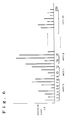
- FIG. 6 is the illustration of a of spectrum grouped into 26 units.
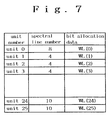
- FIG. 7 is the table of the bit allocation data WL.
- FIG. 8 is the block diagram of the encoding process of the prior art.
- FIG. 1 shows an embodiment of the present invention.
- the quantizations or bit allocations for each frequency interval or unit is set to zero (step numeral 1 ).
- the details of the unit are described in the next paragraph.
- the variance in each unit is calculated from the maximum spectral sample amplitude in the unit (step of numeral 2 ).
- the invention can have variations in step numeral 2 where the variance can be calculated from an average of the spectral components within the unit.
- the maximum spectral sample amplitude was found to be a good worst case representative of the signals in the unit, be it tone-like or noise-like. Further, using the maximum spectral sample saves some computational steps.
- the bandwidth of transmission is computed next (step numeral 3 ).
- step numeral 4 the initial number of bits are allocated according to the approximate mathematical model. Calculation of the remaining bits is then done in step numeral 5 .
- the remaining bits, B are iteratively allocated to the units according to the following steps until the number of bits remaining is less than the minimum number of bits required in the next allocation.
- step numeral 6 If the remaining bits, B is less than the minimum number of bits required in the next allocation, then the iteration is stopped (step numeral 6 ).
- WL′[u] WL[u]+b (step numeral 8 ).
- the unit, spectrum number and bit allocation data (WL) are described as follows.
- the audio signal is transformed into, for example, 256 spectral lines by the MDCT.
- the spectral lines are grouped into plural units.
- the 256 spectral lines are grouped into 26 number units from 0-25.
- the bit allocation data WL(u) is given by an unit as shown in FIG. 7 .
- the spectral line numbers 1 - 8 have the same bit allocation data WL( 0 ) and the spectral line numbers 9 - 12 have same bit allocation data WL( 1 ).
- FIG. 2 shows the flow chart of the bandwidth computation procedure, a modified set of values of the human hearing threshold, obtained from listening tests, is used to determine the bandwidth of the audio signal and to almost eliminate any units where the variance is below the threshold from the next stage of bit allocation.
- the bandwidth counter is set to zero (step numeral 31 ).
- step numeral 32 the block mode is tested. If the short block mode was used in the MDCT process, the thresholds for units having the same frequency resolution is obtained by selecting the lowest threshold from all these units (step numeral 33 ). Each unit's variance is then compared against the threshold (step numeral 34 ). If the variance is above the threshold, the bandwidth counter is incremented (step numeral 35 ).
- the variance in the unit is set to a low dummy value so that it will have the least chance of being allocated any bits in the next stage (step numeral 36 ). This procedure is repeated for all units (step of numeral 37 and 38 ).
- the use the hearing threshold will eliminate units that are irrelevant according to psychoacoustic criteria.
- FIG. 3 shows the procedure of allocating the initial bits to each unit before the iterative process by an approximate mathematical model.
- Step numeral 41 the sum of all the variances and the number of units with variances greater than the low dummy value are calculated.
- Steps numerals 45 , 46 , 47 and 48 check if the bit allocations are below the lowest limit or exceed the highest limit. In either the case, the lowest limit (0 bits) and the highest limit (15 bits) one is set respectively.
- This form of allocation considers that strong signals can have greater in-band masking than weak signals and it is more advantageous to vary the error spectrum more closely to the signal spectrum.
- the mathematical model is able to allocate up to at least 65% of the total number of bits, thus reducing the number of iterations required.
- This invention has been simulated to produce very high audio quality when used in the ATRAC algorithm.
- the bit allocation technique being computationally less intensive takes up a total of 5.7 Mips. This can contribute significantly to a low cost and low power (due to the low frequency of operation) single chip LSI implementation of the encoder.
Landscapes
- Engineering & Computer Science (AREA)
- Computer Networks & Wireless Communication (AREA)
- Signal Processing (AREA)
- Compression, Expansion, Code Conversion, And Decoders (AREA)
Abstract
Description

Claims (21)

Applications Claiming Priority (2)
| Application Number | Priority Date | Filing Date | Title |
|---|---|---|---|
| JP5-030712 | 1993-02-19 | ||
| JP03071293A JP3188013B2 (en) | 1993-02-19 | 1993-02-19 | Bit allocation method for transform coding device |
Publications (1)
| Publication Number | Publication Date |
|---|---|
| US6339757B1 true US6339757B1 (en) | 2002-01-15 |
Family
ID=12311264
Family Applications (1)
| Application Number | Title | Priority Date | Filing Date |
|---|---|---|---|
| US08/161,798 Expired - Lifetime US6339757B1 (en) | 1993-02-19 | 1993-12-06 | Bit allocation method for digital audio signals |
Country Status (3)
| Country | Link |
|---|---|
| US (1) | US6339757B1 (en) |
| EP (1) | EP0612160A3 (en) |
| JP (1) | JP3188013B2 (en) |
Cited By (10)
| Publication number | Priority date | Publication date | Assignee | Title |
|---|---|---|---|---|
| US20040030548A1 (en) * | 2002-08-08 | 2004-02-12 | El-Maleh Khaled Helmi | Bandwidth-adaptive quantization |
| US20050234716A1 (en) * | 2004-04-20 | 2005-10-20 | Vernon Stephen D | Reduced computational complexity of bit allocation for perceptual coding |
| US20070005349A1 (en) * | 1998-10-26 | 2007-01-04 | Stmicroelectronics Asia Pactific (Pte) Ltd. | Multi-precision technique for digital audio encoder |
| US20070129939A1 (en) * | 2005-12-01 | 2007-06-07 | Sasken Communication Technologies Ltd. | Method for scale-factor estimation in an audio encoder |
| US20080140428A1 (en) * | 2006-12-11 | 2008-06-12 | Samsung Electronics Co., Ltd | Method and apparatus to encode and/or decode by applying adaptive window size |
| US20090083619A1 (en) * | 1999-05-21 | 2009-03-26 | E-Numerate Solutions, Inc. | Reusable data markup language |
| US20110013779A1 (en) * | 2009-07-17 | 2011-01-20 | Apple Inc. | Apparatus for testing audio quality of an electronic device |
| US20140207473A1 (en) * | 2013-01-24 | 2014-07-24 | Google Inc. | Rearrangement and rate allocation for compressing multichannel audio |
| US20150371640A1 (en) * | 2014-06-23 | 2015-12-24 | Fujitsu Limited | Audio coding device, audio coding method, and audio codec device |
| US10134402B2 (en) * | 2014-03-19 | 2018-11-20 | Huawei Technologies Co., Ltd. | Signal processing method and apparatus |
Families Citing this family (4)
| Publication number | Priority date | Publication date | Assignee | Title |
|---|---|---|---|---|
| JP3328532B2 (en) | 1997-01-22 | 2002-09-24 | シャープ株式会社 | Digital data encoding method |
| CH695402A5 (en) * | 2000-04-14 | 2006-04-28 | Creaholic Sa | A method for determining a characteristic data set for a sound signal. |
| WO2002093559A1 (en) * | 2001-05-11 | 2002-11-21 | Matsushita Electric Industrial Co., Ltd. | Device to encode, decode and broadcast audio signal with reduced size spectral information |
| JP4823001B2 (en) * | 2006-09-27 | 2011-11-24 | 富士通セミコンダクター株式会社 | Audio encoding device |
Citations (7)
| Publication number | Priority date | Publication date | Assignee | Title |
|---|---|---|---|---|
| WO1989007866A1 (en) | 1988-02-13 | 1989-08-24 | Audio Processing Technology Limited | Method and apparatus for electrical signal coding |
| EP0457391A1 (en) | 1990-05-14 | 1991-11-21 | Koninklijke Philips Electronics N.V. | Encoding method and encoding system comprising a subband coder, and a transmitter comprising an encoding system |
| US5105463A (en) * | 1987-04-27 | 1992-04-14 | U.S. Philips Corporation | System for subband coding of a digital audio signal and coder and decoder constituting the same |
| US5151941A (en) * | 1989-09-30 | 1992-09-29 | Sony Corporation | Digital signal encoding apparatus |
| WO1992017884A1 (en) | 1991-03-29 | 1992-10-15 | Sony Corporation | High efficiency digital data encoding and decoding apparatus |
| US5260980A (en) * | 1990-08-24 | 1993-11-09 | Sony Corporation | Digital signal encoder |
| US5479562A (en) * | 1989-01-27 | 1995-12-26 | Dolby Laboratories Licensing Corporation | Method and apparatus for encoding and decoding audio information |
-
1993
- 1993-02-19 JP JP03071293A patent/JP3188013B2/en not_active Expired - Fee Related
- 1993-12-06 US US08/161,798 patent/US6339757B1/en not_active Expired - Lifetime
-
1994
- 1994-01-27 EP EP94101199A patent/EP0612160A3/en not_active Withdrawn
Patent Citations (7)
| Publication number | Priority date | Publication date | Assignee | Title |
|---|---|---|---|---|
| US5105463A (en) * | 1987-04-27 | 1992-04-14 | U.S. Philips Corporation | System for subband coding of a digital audio signal and coder and decoder constituting the same |
| WO1989007866A1 (en) | 1988-02-13 | 1989-08-24 | Audio Processing Technology Limited | Method and apparatus for electrical signal coding |
| US5479562A (en) * | 1989-01-27 | 1995-12-26 | Dolby Laboratories Licensing Corporation | Method and apparatus for encoding and decoding audio information |
| US5151941A (en) * | 1989-09-30 | 1992-09-29 | Sony Corporation | Digital signal encoding apparatus |
| EP0457391A1 (en) | 1990-05-14 | 1991-11-21 | Koninklijke Philips Electronics N.V. | Encoding method and encoding system comprising a subband coder, and a transmitter comprising an encoding system |
| US5260980A (en) * | 1990-08-24 | 1993-11-09 | Sony Corporation | Digital signal encoder |
| WO1992017884A1 (en) | 1991-03-29 | 1992-10-15 | Sony Corporation | High efficiency digital data encoding and decoding apparatus |
Non-Patent Citations (3)
| Title |
|---|
| IEEE Global Telecommunications Conference, vol. 1, Dec. 2, 1990, New York, pp. 518-522, Mahieux, et al. "Transform Coding of Audio Signals at 64KBIT/S1," p. 520, ¶V "The Bit Allocation." |
| Philips Journal of Research, vol. 44, No. 2/3, Jul. 1989, Eindhoven NL, pp. 329-343, Veldhuis, et al. "Subband Coding of Digital Audio Signals," pp. 338, 1.3-p. 340, 1.33. |
| Veldhuis et al, "Subband Coding of Digital Audio Signals Without Loss Quality," ICASSP-89, 1989, pp. 2009-2012.* |
Cited By (17)
| Publication number | Priority date | Publication date | Assignee | Title |
|---|---|---|---|---|
| US20070005349A1 (en) * | 1998-10-26 | 2007-01-04 | Stmicroelectronics Asia Pactific (Pte) Ltd. | Multi-precision technique for digital audio encoder |
| US7680671B2 (en) * | 1998-10-26 | 2010-03-16 | Stmicroelectronics Asia Pacific Pte. Ltd. | Multi-precision technique for digital audio encoder |
| US20090083619A1 (en) * | 1999-05-21 | 2009-03-26 | E-Numerate Solutions, Inc. | Reusable data markup language |
| US8090577B2 (en) | 2002-08-08 | 2012-01-03 | Qualcomm Incorported | Bandwidth-adaptive quantization |
| US20040030548A1 (en) * | 2002-08-08 | 2004-02-12 | El-Maleh Khaled Helmi | Bandwidth-adaptive quantization |
| US20050234716A1 (en) * | 2004-04-20 | 2005-10-20 | Vernon Stephen D | Reduced computational complexity of bit allocation for perceptual coding |
| US7406412B2 (en) | 2004-04-20 | 2008-07-29 | Dolby Laboratories Licensing Corporation | Reduced computational complexity of bit allocation for perceptual coding |
| US20070129939A1 (en) * | 2005-12-01 | 2007-06-07 | Sasken Communication Technologies Ltd. | Method for scale-factor estimation in an audio encoder |
| US7676360B2 (en) * | 2005-12-01 | 2010-03-09 | Sasken Communication Technologies Ltd. | Method for scale-factor estimation in an audio encoder |
| US20080140428A1 (en) * | 2006-12-11 | 2008-06-12 | Samsung Electronics Co., Ltd | Method and apparatus to encode and/or decode by applying adaptive window size |
| US20110013779A1 (en) * | 2009-07-17 | 2011-01-20 | Apple Inc. | Apparatus for testing audio quality of an electronic device |
| US20140207473A1 (en) * | 2013-01-24 | 2014-07-24 | Google Inc. | Rearrangement and rate allocation for compressing multichannel audio |
| US9336791B2 (en) * | 2013-01-24 | 2016-05-10 | Google Inc. | Rearrangement and rate allocation for compressing multichannel audio |
| US10134402B2 (en) * | 2014-03-19 | 2018-11-20 | Huawei Technologies Co., Ltd. | Signal processing method and apparatus |
| US10832688B2 (en) | 2014-03-19 | 2020-11-10 | Huawei Technologies Co., Ltd. | Audio signal encoding method, apparatus and computer readable medium |
| US20150371640A1 (en) * | 2014-06-23 | 2015-12-24 | Fujitsu Limited | Audio coding device, audio coding method, and audio codec device |
| US9576586B2 (en) * | 2014-06-23 | 2017-02-21 | Fujitsu Limited | Audio coding device, audio coding method, and audio codec device |
Also Published As
| Publication number | Publication date |
|---|---|
| EP0612160A2 (en) | 1994-08-24 |
| JP3188013B2 (en) | 2001-07-16 |
| JPH06242798A (en) | 1994-09-02 |
| EP0612160A3 (en) | 1995-09-27 |
Similar Documents
| Publication | Publication Date | Title |
|---|---|---|
| US6308150B1 (en) | Dynamic bit allocation apparatus and method for audio coding | |
| KR970008640B1 (en) | System for subband coding of a digital audio signal | |
| US5649053A (en) | Method for encoding audio signals | |
| US6246345B1 (en) | Using gain-adaptive quantization and non-uniform symbol lengths for improved audio coding | |
| JP2906646B2 (en) | Voice band division coding device | |
| US5632003A (en) | Computationally efficient adaptive bit allocation for coding method and apparatus | |
| US7548855B2 (en) | Techniques for measurement of perceptual audio quality | |
| EP0709005B1 (en) | Computationally efficient adaptive bit allocation for coding method and apparatus | |
| US6339757B1 (en) | Bit allocation method for digital audio signals | |
| US7155383B2 (en) | Quantization matrices for jointly coded channels of audio | |
| US5752225A (en) | Method and apparatus for split-band encoding and split-band decoding of audio information using adaptive bit allocation to adjacent subbands | |
| CN1078832A (en) | Apparatus and method for data compression using weighted signal quantization bit allocation | |
| EP1998321B1 (en) | Method and apparatus for encoding/decoding a digital signal | |
| JPH06232761A (en) | Method and device for high efficiency coding or decoding | |
| US7634400B2 (en) | Device and process for use in encoding audio data | |
| EP1175670B2 (en) | Using gain-adaptive quantization and non-uniform symbol lengths for audio coding | |
| US7613609B2 (en) | Apparatus and method for encoding a multi-channel signal and a program pertaining thereto | |
| US20040098268A1 (en) | MPEG audio encoding method and apparatus | |
| JP2993324B2 (en) | Highly efficient speech coding system | |
| JP2729013B2 (en) | A threshold control quantization decision method for audio signals. | |
| KR19990056432A (en) | A high-speed bit allocation method in a digital audio encoding apparatus | |
| JPH11196056A (en) | Audio signal processing method |
Legal Events
| Date | Code | Title | Description |
|---|---|---|---|
| AS | Assignment |
Owner name: MASTSUSHITA ELECTRIC INDUSTRIAL CO., LTD. A COR Free format text: ASSIGNMENT OF ASSIGNORS INTEREST;ASSIGNORS:TEH, DO HUI;TAN, PEK YEW;NEO, SUA HONG;REEL/FRAME:006798/0252 Effective date: 19931004 |
|
| AS | Assignment |
Owner name: MATSUSHITA ELECTRIC INDUSTRIAL CO., LTD., JAPAN Free format text: CORRECTION OF NOTICE OF RECORDATION OF ASSIGNMENT RECORDED ON 12-6-1993 AT REEL/FRAME 6798/0252 DUE TO APPLICANTS ERROR. PLEASE CHANGE THE NAME OF THE ASSIGNEE FROM "MASTSUSHITA ELECTRIC INDUSTRIAL CO., LTD." TO MATSUSHITA ELECTRIC INDUSTRIAL CO., LTD.;ASSIGNORS:TEH, DO HUI;TAN, PEK YEW;NEO, SUA HONG;REEL/FRAME:008697/0210 Effective date: 19931004 |
|
| AS | Assignment |
Owner name: MATSUSHITA ELECTRIC INDUSTRIAL CO., LTD., JAPAN Free format text: RE-RECORDED TO CORRECT THE ADDRESS OF THE ASSIGNEE;ASSIGNORS:TEH, DO HUI;TAN, PEK YEW;NEO, SUA HONG;REEL/FRAME:008787/0297 Effective date: 19931004 |
|
| STCF | Information on status: patent grant |
Free format text: PATENTED CASE |
|
| FEPP | Fee payment procedure |
Free format text: PAYOR NUMBER ASSIGNED (ORIGINAL EVENT CODE: ASPN); ENTITY STATUS OF PATENT OWNER: LARGE ENTITY |
|
| FPAY | Fee payment |
Year of fee payment: 4 |
|
| FPAY | Fee payment |
Year of fee payment: 8 |
|
| AS | Assignment |
Owner name: PANASONIC CORPORATION, JAPAN Free format text: CHANGE OF NAME;ASSIGNOR:MATSUSHITA ELECTRIC INDUSTRIAL CO., LTD.;REEL/FRAME:029283/0355 Effective date: 20081001 |
|
| AS | Assignment |
Owner name: DOLBY INTERNATIONAL AB, NETHERLANDS Free format text: ASSIGNMENT OF ASSIGNORS INTEREST;ASSIGNOR:PANASONIC CORPORATION;REEL/FRAME:029654/0754 Effective date: 20121030 |
|
| FPAY | Fee payment |
Year of fee payment: 12 |
|
| IPR | Aia trial proceeding filed before the patent and appeal board: inter partes review |
Free format text: TRIAL NO: IPR2024-01354 Opponent name: ROKU, INC. Effective date: 20240909 |