US6339688B1 - Air filtering apparatus of liquid electrophotographic printer - Google Patents
Air filtering apparatus of liquid electrophotographic printer Download PDFInfo
- Publication number
- US6339688B1 US6339688B1 US09/604,982 US60498200A US6339688B1 US 6339688 B1 US6339688 B1 US 6339688B1 US 60498200 A US60498200 A US 60498200A US 6339688 B1 US6339688 B1 US 6339688B1
- Authority
- US
- United States
- Prior art keywords
- longitudinal
- slot
- filtering apparatus
- air filtering
- air
- Prior art date
- Legal status (The legal status is an assumption and is not a legal conclusion. Google has not performed a legal analysis and makes no representation as to the accuracy of the status listed.)
- Expired - Lifetime
Links
Images


Classifications
-
- G—PHYSICS
- G03—PHOTOGRAPHY; CINEMATOGRAPHY; ANALOGOUS TECHNIQUES USING WAVES OTHER THAN OPTICAL WAVES; ELECTROGRAPHY; HOLOGRAPHY
- G03G—ELECTROGRAPHY; ELECTROPHOTOGRAPHY; MAGNETOGRAPHY
- G03G15/00—Apparatus for electrographic processes using a charge pattern
-
- G—PHYSICS
- G03—PHOTOGRAPHY; CINEMATOGRAPHY; ANALOGOUS TECHNIQUES USING WAVES OTHER THAN OPTICAL WAVES; ELECTROGRAPHY; HOLOGRAPHY
- G03G—ELECTROGRAPHY; ELECTROPHOTOGRAPHY; MAGNETOGRAPHY
- G03G15/00—Apparatus for electrographic processes using a charge pattern
- G03G15/02—Apparatus for electrographic processes using a charge pattern for laying down a uniform charge, e.g. for sensitising; Corona discharge devices
- G03G15/0258—Apparatus for electrographic processes using a charge pattern for laying down a uniform charge, e.g. for sensitising; Corona discharge devices provided with means for the maintenance of the charging apparatus, e.g. cleaning devices, ozone removing devices G03G15/0225, G03G15/0291 takes precedence
-
- G—PHYSICS
- G03—PHOTOGRAPHY; CINEMATOGRAPHY; ANALOGOUS TECHNIQUES USING WAVES OTHER THAN OPTICAL WAVES; ELECTROGRAPHY; HOLOGRAPHY
- G03G—ELECTROGRAPHY; ELECTROPHOTOGRAPHY; MAGNETOGRAPHY
- G03G21/00—Arrangements not provided for by groups G03G13/00 - G03G19/00, e.g. cleaning, elimination of residual charge
- G03G21/20—Humidity or temperature control also ozone evacuation; Internal apparatus environment control
- G03G21/206—Conducting air through the machine, e.g. for cooling, filtering, removing gases like ozone
Definitions
- the present invention relates to an air filtering apparatus in a liquid electrophotographic printer, and more particularly, an air filtering apparatus for effectively sucking air in the liquid electrophotographic printer and removing pollutants contained in the air.
- a liquid electrophotographic printer emits various types of pollutants, such as solvent and carbon materials and ozone, during a developing and printing process.
- pollutants are generated from printing mechanisms and materials when a printable image is developed and printed on a sheet of paper by using the printing, materials in the developing and printing process.
- Air inside of the printer is contaminated with the pollutants which cause serious problems against both the printable image and the printing mechanisms.
- the air containing the pollutants has a more harmful effects on human being if it is blown out of the printer.
- the solvent evaporates during the developing process into the air inside of the printer and sticks to a laser scanner and a photoreceptor web bearing the printable image in the printer while the carbon material is generated during drying the printable image formed on the photoreceptor web and transferring the printable image from the photoreceptor web to the sheet of paper in the developing and printing process.
- the ozone is generated from a plurality of chargers disposed adjacent to the photoreceptor web during initializing and changing the photoreceptor web with a high voltage.
- a liquid electrophotographic printer with a filtering apparatus including a charger having a discharge wire charging a photoreceptor web to a predetermined level of electric potential, a laser scanner forming an electrostatic latent image on the charged photoreceptor web, a development unit developing the electrostatic latent image to a printable image, a transfer unit printing the printable image on a sheet of paper, a suction device having a duct mounted on the charger and sucking air in the printer, and a filtering device filtering pollutants contained in the air sucked by the suction device.
- the suction device of the air filtering apparatus includes a discharge wire connected to a voltage source, a holder supporting the discharge wire, a grid net attached to one side of the holder and facing the photoreceptor web, a plurality of openings formed on the holder, a cover coupled to the other side of the holder, a hollow portion formed inside of the cover, a slot formed on the cover and connecting the openings to the hollow portion, an exhaust hole connected to one end of the hollow portion, and a suction pump connected to the exhaust hole and sucking air inside of the printer through the openings, the slot, the exhaust hole, and the exhaust hole.
- the slot varies in width from one end to the other end of the slot.
- the width of the slot disposed remote from the exhaust hole is greater than the slot disposed adjacent to the exhaust hole.
- the width of the slot increases from one end of the slot to the other end of the slot.
- the suction device includes a discharge wire connected to a voltage source, a shield plate accommodating the discharge wire, a plurality of slots formed on the shield plate, a holder attached to the shield plate, a passage formed between the shield plate and the holder, and an exhaust hole formed on one end of the passage. Air around the discharge wire is sucked through the slots, the passage, and the exhaust hole.
- the suction device is mounted on a main charger initializing the photoreceptor web.
- a plurality of suction devices mounted on each corresponding charger charging the photoreceptor web are disposed adjacent to each corresponding development unit.
- Each exhaust hole of the suction devices is connected to a shared pipe.
- the suction pump is connected to the shared pipe.
- a plurality of filters suitable to filter pollutants such as solvent and carbon materials and ozone are connected to the suction pump.
- the suction devices disposed adjacent to the transfer unit includes a main duct having two branch ducts disposed adjacent to both sides of the transfer unit and slots formed on the branch ducts.
- An exhaust hole is formed on one end of the main duct and coupled to a suction pump.
- a plurality of filters are connected to the suction pump in order to remove pollutants contained in the air inside of the printer.
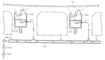
- FIG. 1 is a schematic diagram of major elements of conventional liquid electrophotographic printer
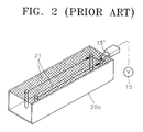
- FIG. 2 is a perspective view showing a main charger shown in FIG. 1;
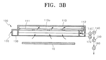
- FIGS. 3A and 3B are an exploded perspective view and a cross-sectional view showing an air filtering apparatus according to the principle of the present invention, respectively;
- FIGS. 4A and 4 b are an exploded perspective view and a cross-sectional view showing an air filtering apparatus according to a second embodiment of the present invention, respectively.
- FIG. 5 is a partially exploded perspective view showing an air filtering apparatus according to a third embodiment of the present invention.
- FIG. 1 shows a conventional liquid electrophotographic printer such as a typical color laser printer.
- a photoreceptor web 10 circulates around a plurality of rollers 11 while being supported by rollers 11 .
- An electrostatic latent image is formed by a laser scanner 13 on photoreceptor web 10 .
- the electrostatic latent image is developed by a development unit 12 , and a printable image of a predetermined color is formed on photoreceptor web 10 .
- the developed printable image is printed on a sheet of paper S by a transfer unit 14 .
- Development unit 12 uses a developer, which is a mixture of toner powder and a liquid solvent, in developing the electrostatic latent image.
- the solvent evaporates during a developing process at the development unit 12 and a transferring process at the transfer unit 14 , and the evaporated solvent remains in air inside of the printer.
- the evaporated solvent sticks to photoreceptor web 10 or laser scanner 13 and cause a serious problem in forming and developing the electrostatic latent image on photoreceptor web 10 and printing the printable image on the paper S.
- a charger charges a surface of photoreceptor web 10 to predetermined electric potential so that the electrostatic latent image can be formed on photoreceptor web 10 .
- the charger includes a main charger 20 a performing initialization by charging photoreceptor web 10 after an printable image has been printed on a sheet of paper S and a topping charger 20 b charging photoreceptor web 10 .
- An electrostatic latent image is formed on photoreceptor web 10 whenever photoreceptor web 10 passes each development unit 12 .
- the operating principles of these two chargers are same.
- the main charger 20 a has discharge wires 21 discharging photoreceptor web 10 when a voltage is supplied from a power source 15 to discharge wires 21 through an electrode 15 ′, as shown in FIG. 2 .
- Photoreceptor web 10 is charged to a predetermined voltage by a corona discharge of the discharge wires 21 .
- Photoreceptor web 10 must be charged to about 600 volts while discharge wires 21 themselves discharge a very high voltage reaching an instantaneous voltage of several thousand volts.
- Some oxygens (O 2 ) near the charger are changed to ozone (O 3 ) due to the high voltage.
- Ozone has strong bleaching and oxidizing capabilities so that life span of elements, such as a photoreceptor web, a developing unit, and a transferring unit, in the printer may be shortened when the amount of ozone increases with repeated use of the printer.
- an air filtering apparatus of a liquid electrophotographic printer is mounted on a main charger 100 charging and initializing a photoreceptor web 10 .
- the air filter apparatus mounted on main charger 100 is used for mainly removing the ozone generated from main charger 100 , both ozone generated at a topping charger and solvent and carbon materials generated from a developing unit and a transferring unit are removed by the filtering apparatus mounted on main charger 100 .
- a holder 120 contains and supports a discharge wire 101 .
- a first electric power V 1 171 coupled to discharge wire 101 applies a voltage of 6-7 kV to discharge wire 101 .
- An upper portion of holder 120 is open to photoreceptor web 10 and covered by a grid net 130 .
- a plurality of openings 121 such as slits are formed on bottom portion of holder 120 .
- Grid net 130 is installed to control an electric potential charged to 600-700 V by a second electric power V 2 172 which is independent of the first electric power V 1 171 .
- This arrangement is for achieving a state of balance between photoreceptor web 10 and grid net 130 after photoreceptor web 10 is charged to 600-700 V which is the electric potential charged to grid net 130 .
- the electric potential of photoreceptor web 10 can be adjusted by adjusting the electric potential of gridnet 130 .
- An upper surface of holder 120 made of metal contacts one side of grid net 130 so that the second electric power 172 and the grid net 130 can be electrical
- a cover 110 is coupled to a bottom of holder 120 where the openings 121 are formed.
- a hollow portion 110 a is formed inside of the cover 110 and, a slot 111 is formed on cover 110 and couples hollow portion 110 a to openings 121 .
- An exhaust hole 112 are formed on one end of hollow portion 110 a .
- a suction pump 140 is connected to the exhaust hole 112 of cover 110 .
- a platinum catalyst filter 150 and a carbon filter 160 as a filtering device are installed along the exhaust path and connected to suction pump 140 .
- the filtering device filters out pollutants from the sucked air.
- the platinum catalyst filter 150 decomposes the ozone contained in the air utilizing the principle that the decomposition of ozone is expedited as it acts on platinum, lead oxide, manganese oxide or copper oxide.
- the carbon filter 160 is a filter having superior absorbing capability like active carbon and is installed to collect a solvent contained in the air. As a result, while passing through the filters, the ozone and the solvent are filtered, and filtered air is exhausted to an outside of the printer. Therefore, after the air inside of the printer is sucked to be filtered, and ozone and solvent are removed from the sucked air, the air inside the printer is exhausted to the outside of the printer or returned to the inside of the printer.
- the width h 1 of slot 111 at the side of the exhaust hole 112 is about 0.5 mm, and slot 111 becomes wider to about 2.0 mm at the position of width h 2 of slot 11 .
- This is to compensate for the difference in the amount of sucked air by suction pump 140 through slot 111 because suction power at the position near exhaust hole 112 is greater than at the opposite side remote from exhaust hole 112 .
- the air is uniformly sucked through the entire length of slot 111 .
- suction pump 140 operates, a nearly same amount of air along the entire length of the slot 111 is sucked from slot 111 and exhausted through exhaust hole 112 .
- FIGS. 4A and 4B show an air filtering apparatus mounted on a topping charger 200 mainly used for removing ozone generated from topping charger 200 while the ozone generated from main charger 100 and the solvent and carbon materials generated from development unit 12 and transfer unit 14 are also removed by the air filter mounted on topping, charger 200 .
- a holder 210 supports a discharge wire 201 of topping charger 200 , and a shield plate 220 is coupled to holder 210 and disposed between holder 210 and discharger wire 200 .
- a slot 221 is formed lengthwise on shield plate 220 . When holder 210 is coupled to shield plate 220 , a path 210 a is formed between holder 210 and shield plate 220 and connected to slot 221 .
- An exhaust hole 211 is formed at one end of holder 210 and connected to a shared pipe 270 connected to a suction pump 240 .
- Shared pipe 270 is connected between suction pump 240 and each exhaust hole 211 so that an exhaust path coupled to one suction pump 240 is shared with the adjacent suction device mounted on each topping charger 200 as shown in FIG. 4B.
- a platinum catalyst filter 250 and a carbon filter 260 are coupled to suction pump 240 .
- Reference numeral 271 denotes a first electric power for applying a first voltage to discharge wire 201 .
- Reference numeral 272 denotes a second electric power for applying a second voltage to shield case 220 performing a function of controlling the electric potential discharged from discharge wire 201 to photoreceptor web 10 like the grid net 130 of FIG. 3 A.
- Reference numeral 280 denotes an insulator.
- slot 221 When suction pump 240 operates, air near topping charger 200 is sucked through slot 221 of shield plate 220 , path 210 a and exhaust hole 211 , and then exhausted through shared pipe 270 . After platinum catalyst filter 250 and carbon filter 260 filter the ozone and the solvent and carbon materials, the filtered air is exhausted.
- the shape of slot 221 is formed to be narrower at a position near exhaust hole 211 and wider at an opposite side remote from exhaust hole 211 .
- FIG. 5 shows an air filtering apparatus mounted adjacent to transfer unit 14 transferring the printable image from photoreceptor web 10 to a sheet of paper S.
- a main duct 300 is disposed adjacent to and above transfer unit 14 .
- a slot 301 like an inlet is formed on a bottom of main duct 300 and is facing transfer unit 14 .
- Two branch ducts of main duct 300 are disposed on both sides of transfer unit as shown in FIG. 5 . Each one end of the two branches meets at an exhaust hole 302 .
- a connection pipe 310 is connected to exhaust hole 302 of main duct 300 so that air surrounding transfer unit 14 can be sucked through two branch ducts of main duct 300 , exhaust hole 302 , and connection pipe 310 into a suction pump 320 . Pollutants contained in the air sucked by suction pump 320 is removed by a platinum catalyst filter 330 and a carbon filter 340 .
- the air filtering apparatus mounted on either a main charger initializing the photoreceptor web or a top charger charging the photoreceptor web or adjacent to a transfer unit transferring a printable image from the photoreceptor web to a sheet of paper filters air inside of the printer and removes from the air pollutants such as ozone generated from main and top chargers and the solvent and carbon materials generated from a developing unit. Since the filtered air is exhausted, environmental and pollution problems can be reduced, and harmful effects on printing mechanisms by repeated use of the printer can be removed. Therefore, life spans of mechanisms in the printer may be extended, and the quality of the printable image can be maintained.
Landscapes
- Physics & Mathematics (AREA)
- General Physics & Mathematics (AREA)
- Engineering & Computer Science (AREA)
- Life Sciences & Earth Sciences (AREA)
- Atmospheric Sciences (AREA)
- Biodiversity & Conservation Biology (AREA)
- Ecology (AREA)
- Environmental & Geological Engineering (AREA)
- Environmental Sciences (AREA)
- Plasma & Fusion (AREA)
- Control Or Security For Electrophotography (AREA)
- Electrostatic Charge, Transfer And Separation In Electrography (AREA)
Abstract
Description
Claims (37)
Applications Claiming Priority (2)
| Application Number | Priority Date | Filing Date | Title |
|---|---|---|---|
| KR99-42497 | 1999-10-02 | ||
| KR1019990042497A KR100338761B1 (en) | 1999-10-02 | 1999-10-02 | Inner air cleaning apparatus for liquid electrophotographic printer |
Publications (1)
| Publication Number | Publication Date |
|---|---|
| US6339688B1 true US6339688B1 (en) | 2002-01-15 |
Family
ID=19613767
Family Applications (1)
| Application Number | Title | Priority Date | Filing Date |
|---|---|---|---|
| US09/604,982 Expired - Lifetime US6339688B1 (en) | 1999-10-02 | 2000-06-28 | Air filtering apparatus of liquid electrophotographic printer |
Country Status (2)
| Country | Link |
|---|---|
| US (1) | US6339688B1 (en) |
| KR (1) | KR100338761B1 (en) |
Cited By (13)
| Publication number | Priority date | Publication date | Assignee | Title |
|---|---|---|---|---|
| EP1367454A1 (en) * | 2002-05-27 | 2003-12-03 | Seiko Epson Corporation | Image forming apparatus using a corona charger with conductive shield and ventilation duct |
| US20040105697A1 (en) * | 2002-12-03 | 2004-06-03 | Samsung Electronics Co., Ltd. | Gas exhausting apparatus for wet electrophotographic image forming device and method thereof |
| US20040253017A1 (en) * | 2003-06-10 | 2004-12-16 | Lee Michael H. | Hard imaging device vapor removal systems, hard imaging devices, and hard imaging methods. |
| US20060024082A1 (en) * | 2004-07-29 | 2006-02-02 | Omer Gila | Apparatus and method for reducing contamination of an image transfer device |
| US20060024083A1 (en) * | 2004-07-06 | 2006-02-02 | Sharp Kabushiki Kaisha | Image forming apparatus |
| US20060269326A1 (en) * | 2005-05-24 | 2006-11-30 | Xerox Corporation | Dicorotron having a shield insert |
| US20080226334A1 (en) * | 2007-03-16 | 2008-09-18 | Fuji Xerox Co., Ltd. | Discharger, image carrier unit, and image forming apparatus |
| US20090090245A1 (en) * | 2007-10-04 | 2009-04-09 | Donaldson Company, Inc. | Filter assembly |
| US20090208248A1 (en) * | 2005-10-20 | 2009-08-20 | Kabushiki Kaisha Toshiba | Image forming apparatus and attaching method of charger unit in image forming apparatus |
| US20090285595A1 (en) * | 2008-05-19 | 2009-11-19 | Xerox Corporation | Discorotron Assembly with Titanium Shield with Integrated Grid Mounting and Electrical Connection |
| CN102225666A (en) * | 2011-06-03 | 2011-10-26 | 苏州万图明电子软件有限公司 | Printer with suction holes |
| EP2250026B2 (en) † | 2009-03-19 | 2014-09-10 | KHS GmbH | Printing apparatus for printing bottles or similar containers |
| US11123845B2 (en) | 2017-06-21 | 2021-09-21 | Hp Indigo B.V. | Vacuum tables |
Families Citing this family (2)
| Publication number | Priority date | Publication date | Assignee | Title |
|---|---|---|---|---|
| KR100481544B1 (en) * | 2002-09-10 | 2005-04-08 | 삼성전자주식회사 | Wet-type electro photographic printer with a photocatalystic filter |
| KR100610332B1 (en) * | 2004-05-11 | 2006-08-09 | 삼성전자주식회사 | Ozone purification unit and wet electrophotographic imaging apparatus |
Citations (2)
| Publication number | Priority date | Publication date | Assignee | Title |
|---|---|---|---|---|
| US4264184A (en) * | 1976-12-24 | 1981-04-28 | Olympus Optical Co., Ltd. | Ozone removing device for electrographic apparatus |
| US5742874A (en) * | 1995-12-07 | 1998-04-21 | Konica Corporation | Charging device |
-
1999
- 1999-10-02 KR KR1019990042497A patent/KR100338761B1/en not_active Expired - Fee Related
-
2000
- 2000-06-28 US US09/604,982 patent/US6339688B1/en not_active Expired - Lifetime
Patent Citations (2)
| Publication number | Priority date | Publication date | Assignee | Title |
|---|---|---|---|---|
| US4264184A (en) * | 1976-12-24 | 1981-04-28 | Olympus Optical Co., Ltd. | Ozone removing device for electrographic apparatus |
| US5742874A (en) * | 1995-12-07 | 1998-04-21 | Konica Corporation | Charging device |
Cited By (23)
| Publication number | Priority date | Publication date | Assignee | Title |
|---|---|---|---|---|
| EP1367454A1 (en) * | 2002-05-27 | 2003-12-03 | Seiko Epson Corporation | Image forming apparatus using a corona charger with conductive shield and ventilation duct |
| US20050074254A1 (en) * | 2002-05-27 | 2005-04-07 | Seiko Epson Corporation | Image forming apparatus |
| US6944413B2 (en) | 2002-05-27 | 2005-09-13 | Seiko Epson Corporation | Image forming apparatus for preventing the adhesion of discharge products in a charger thereby preventing image defects |
| US20040105697A1 (en) * | 2002-12-03 | 2004-06-03 | Samsung Electronics Co., Ltd. | Gas exhausting apparatus for wet electrophotographic image forming device and method thereof |
| US6996352B2 (en) * | 2002-12-03 | 2006-02-07 | Samsung Electronics Co., Ltd. | Gas exhausting apparatus for wet electrophotographic image forming device and method thereof |
| US20040253017A1 (en) * | 2003-06-10 | 2004-12-16 | Lee Michael H. | Hard imaging device vapor removal systems, hard imaging devices, and hard imaging methods. |
| US6934486B2 (en) | 2003-06-10 | 2005-08-23 | Hewlett-Packard Development Company, L.P. | Hard imaging device vapor removal systems, hard imaging devices, and hard imaging methods |
| CN1719346B (en) * | 2004-07-06 | 2011-03-30 | 夏普株式会社 | Image forming apparatus |
| US20060024083A1 (en) * | 2004-07-06 | 2006-02-02 | Sharp Kabushiki Kaisha | Image forming apparatus |
| US7415218B2 (en) * | 2004-07-06 | 2008-08-19 | Sharp Kabushiki Kaisha | Image forming apparatus having charging unit with separate intake and exhaust ducts |
| US7174114B2 (en) * | 2004-07-29 | 2007-02-06 | Hewlett-Packard Development Company, Lp. | Apparatus and method for reducing contamination of an image transfer device |
| US20060024082A1 (en) * | 2004-07-29 | 2006-02-02 | Omer Gila | Apparatus and method for reducing contamination of an image transfer device |
| US20060269326A1 (en) * | 2005-05-24 | 2006-11-30 | Xerox Corporation | Dicorotron having a shield insert |
| US20090208248A1 (en) * | 2005-10-20 | 2009-08-20 | Kabushiki Kaisha Toshiba | Image forming apparatus and attaching method of charger unit in image forming apparatus |
| US7817937B2 (en) * | 2005-10-20 | 2010-10-19 | Kabushiki Kaisha Toshiba | Image forming apparatus and attaching method of charger unit in image forming apparatus to install/remove main chargers |
| US20080226334A1 (en) * | 2007-03-16 | 2008-09-18 | Fuji Xerox Co., Ltd. | Discharger, image carrier unit, and image forming apparatus |
| US7835667B2 (en) * | 2007-03-16 | 2010-11-16 | Fuji Xerox Co., Ltd. | Discharger, image carrier unit, and image forming apparatus |
| US20090090245A1 (en) * | 2007-10-04 | 2009-04-09 | Donaldson Company, Inc. | Filter assembly |
| US20090285595A1 (en) * | 2008-05-19 | 2009-11-19 | Xerox Corporation | Discorotron Assembly with Titanium Shield with Integrated Grid Mounting and Electrical Connection |
| US7865107B2 (en) * | 2008-05-19 | 2011-01-04 | Xerox Corporation | Discorotron assembly with titanium shield with integrated grid mounting and electrical connection |
| EP2250026B2 (en) † | 2009-03-19 | 2014-09-10 | KHS GmbH | Printing apparatus for printing bottles or similar containers |
| CN102225666A (en) * | 2011-06-03 | 2011-10-26 | 苏州万图明电子软件有限公司 | Printer with suction holes |
| US11123845B2 (en) | 2017-06-21 | 2021-09-21 | Hp Indigo B.V. | Vacuum tables |
Also Published As
| Publication number | Publication date |
|---|---|
| KR100338761B1 (en) | 2002-05-30 |
| KR20010035771A (en) | 2001-05-07 |
Similar Documents
| Publication | Publication Date | Title |
|---|---|---|
| US6339688B1 (en) | Air filtering apparatus of liquid electrophotographic printer | |
| JP4423312B2 (en) | Electronics | |
| EP1080395B1 (en) | Charger for electrostatic printing system | |
| US7973291B2 (en) | Electronic apparatus | |
| EP0778502A1 (en) | Charging device | |
| US8521052B2 (en) | Image forming apparatus | |
| US8965238B2 (en) | Charging device provided with a non-contact type discharge electrode and image forming apparatus including the charging device | |
| US6411788B1 (en) | Image forming apparatus with air flow regulator | |
| US7970318B2 (en) | Charging device and image forming device using same | |
| US6917773B2 (en) | Image forming apparatus | |
| KR100524063B1 (en) | liquid electrophotographic printer | |
| JPH09197766A (en) | Discharge electrode device | |
| CN113767339A (en) | Cooling and air purifying structure of image forming apparatus | |
| JPS63226681A (en) | Paper guide device for electrophotographic equipment | |
| JP3833233B2 (en) | Image forming apparatus | |
| JPH02103063A (en) | image forming device | |
| US7421222B2 (en) | Electrophotographic device with contaminant-resistant photoconductor and charger | |
| JPH0990828A (en) | Image forming device | |
| JPH01237569A (en) | Corona discharge device | |
| JP2503289Y2 (en) | Paper guide device for electrophotographic device | |
| JPH0667509A (en) | Discharge device | |
| JPH09160451A (en) | Electrophotographic recording device | |
| JP4689554B2 (en) | Charging device and image forming apparatus using the same | |
| JPH03225380A (en) | electrophotographic equipment | |
| JP2002207348A (en) | Corona discharge device and image forming device |
Legal Events
| Date | Code | Title | Description |
|---|---|---|---|
| AS | Assignment |
Owner name: SAMSUNG ELECTRONICS CO., LTD., KOREA, REPUBLIC OF Free format text: ASSIGNMENT OF ASSIGNORS INTEREST;ASSIGNORS:CHO, MIN-SU;SEO, JI-WON;REEL/FRAME:011083/0191 Effective date: 20000708 |
|
| STCF | Information on status: patent grant |
Free format text: PATENTED CASE |
|
| FPAY | Fee payment |
Year of fee payment: 4 |
|
| FPAY | Fee payment |
Year of fee payment: 8 |
|
| FEPP | Fee payment procedure |
Free format text: PAYOR NUMBER ASSIGNED (ORIGINAL EVENT CODE: ASPN); ENTITY STATUS OF PATENT OWNER: LARGE ENTITY |
|
| FPAY | Fee payment |
Year of fee payment: 12 |
|
| AS | Assignment |
Owner name: S-PRINTING SOLUTION CO., LTD., KOREA, REPUBLIC OF Free format text: ASSIGNMENT OF ASSIGNORS INTEREST;ASSIGNOR:SAMSUNG ELECTRONICS CO., LTD;REEL/FRAME:041852/0125 Effective date: 20161104 |
|
| AS | Assignment |
Owner name: HP PRINTING KOREA CO., LTD., KOREA, REPUBLIC OF Free format text: CHANGE OF NAME;ASSIGNOR:S-PRINTING SOLUTION CO., LTD.;REEL/FRAME:047370/0405 Effective date: 20180316 |
|
| AS | Assignment |
Owner name: HP PRINTING KOREA CO., LTD., KOREA, REPUBLIC OF Free format text: CORRECTIVE ASSIGNMENT TO CORRECT THE DOCUMENTATION EVIDENCING THE CHANGE OF NAME PREVIOUSLY RECORDED ON REEL 047370 FRAME 0405. ASSIGNOR(S) HEREBY CONFIRMS THE CHANGE OF NAME;ASSIGNOR:S-PRINTING SOLUTION CO., LTD.;REEL/FRAME:047769/0001 Effective date: 20180316 |
|
| AS | Assignment |
Owner name: HP PRINTING KOREA CO., LTD., KOREA, REPUBLIC OF Free format text: CHANGE OF LEGAL ENTITY EFFECTIVE AUG. 31, 2018;ASSIGNOR:HP PRINTING KOREA CO., LTD.;REEL/FRAME:050938/0139 Effective date: 20190611 |
|
| AS | Assignment |
Owner name: HEWLETT-PACKARD DEVELOPMENT COMPANY, L.P., TEXAS Free format text: CONFIRMATORY ASSIGNMENT EFFECTIVE NOVEMBER 1, 2018;ASSIGNOR:HP PRINTING KOREA CO., LTD.;REEL/FRAME:050747/0080 Effective date: 20190826 |