US6339268B1 - Cooling ventilation circuit for rotor end winding and slot end region cooling - Google Patents
Cooling ventilation circuit for rotor end winding and slot end region cooling Download PDFInfo
- Publication number
- US6339268B1 US6339268B1 US09/496,727 US49672700A US6339268B1 US 6339268 B1 US6339268 B1 US 6339268B1 US 49672700 A US49672700 A US 49672700A US 6339268 B1 US6339268 B1 US 6339268B1
- Authority
- US
- United States
- Prior art keywords
- cooling gas
- passage
- turn
- rotor
- coils
- Prior art date
- Legal status (The legal status is an assumption and is not a legal conclusion. Google has not performed a legal analysis and makes no representation as to the accuracy of the status listed.)
- Expired - Lifetime
Links
- 238000004804 winding Methods 0.000 title claims abstract description 64
- 238000001816 cooling Methods 0.000 title claims abstract description 42
- 238000009423 ventilation Methods 0.000 title claims abstract description 42
- 239000000112 cooling gas Substances 0.000 claims abstract description 70
- 238000004891 communication Methods 0.000 claims abstract description 6
- 239000007789 gas Substances 0.000 claims description 34
- 238000007599 discharging Methods 0.000 claims description 3
- RYGMFSIKBFXOCR-UHFFFAOYSA-N Copper Chemical compound [Cu] RYGMFSIKBFXOCR-UHFFFAOYSA-N 0.000 description 15
- 229910052802 copper Inorganic materials 0.000 description 15
- 239000010949 copper Substances 0.000 description 15
- 238000003754 machining Methods 0.000 description 5
- 239000004020 conductor Substances 0.000 description 4
- 238000010276 construction Methods 0.000 description 4
- 238000005242 forging Methods 0.000 description 3
- 238000004513 sizing Methods 0.000 description 3
- XEEYBQQBJWHFJM-UHFFFAOYSA-N Iron Chemical compound [Fe] XEEYBQQBJWHFJM-UHFFFAOYSA-N 0.000 description 2
- 229910000831 Steel Inorganic materials 0.000 description 2
- 230000000903 blocking effect Effects 0.000 description 2
- 238000013461 design Methods 0.000 description 2
- 238000009826 distribution Methods 0.000 description 2
- 238000009413 insulation Methods 0.000 description 2
- 238000000034 method Methods 0.000 description 2
- 239000007787 solid Substances 0.000 description 2
- 125000006850 spacer group Chemical group 0.000 description 2
- 239000010959 steel Substances 0.000 description 2
- UFHFLCQGNIYNRP-UHFFFAOYSA-N Hydrogen Chemical compound [H][H] UFHFLCQGNIYNRP-UHFFFAOYSA-N 0.000 description 1
- 230000008859 change Effects 0.000 description 1
- 230000001010 compromised effect Effects 0.000 description 1
- 235000019628 coolness Nutrition 0.000 description 1
- 230000007812 deficiency Effects 0.000 description 1
- 238000005553 drilling Methods 0.000 description 1
- 230000008030 elimination Effects 0.000 description 1
- 238000003379 elimination reaction Methods 0.000 description 1
- 239000001257 hydrogen Substances 0.000 description 1
- 229910052739 hydrogen Inorganic materials 0.000 description 1
- 229910052742 iron Inorganic materials 0.000 description 1
- 238000002955 isolation Methods 0.000 description 1
- 230000014759 maintenance of location Effects 0.000 description 1
- 230000007246 mechanism Effects 0.000 description 1
- 238000003801 milling Methods 0.000 description 1
- 238000012986 modification Methods 0.000 description 1
- 230000004048 modification Effects 0.000 description 1
- 230000008569 process Effects 0.000 description 1
- 238000005086 pumping Methods 0.000 description 1
- 238000004080 punching Methods 0.000 description 1
- 230000009467 reduction Effects 0.000 description 1
- 230000000717 retained effect Effects 0.000 description 1
- 238000012546 transfer Methods 0.000 description 1
- 230000007704 transition Effects 0.000 description 1
Images


Classifications
-
- H—ELECTRICITY
- H02—GENERATION; CONVERSION OR DISTRIBUTION OF ELECTRIC POWER
- H02K—DYNAMO-ELECTRIC MACHINES
- H02K1/00—Details of the magnetic circuit
- H02K1/06—Details of the magnetic circuit characterised by the shape, form or construction
- H02K1/22—Rotating parts of the magnetic circuit
- H02K1/32—Rotating parts of the magnetic circuit with channels or ducts for flow of cooling medium
-
- H—ELECTRICITY
- H02—GENERATION; CONVERSION OR DISTRIBUTION OF ELECTRIC POWER
- H02K—DYNAMO-ELECTRIC MACHINES
- H02K3/00—Details of windings
- H02K3/04—Windings characterised by the conductor shape, form or construction, e.g. with bar conductors
- H02K3/24—Windings characterised by the conductor shape, form or construction, e.g. with bar conductors with channels or ducts for cooling medium between the conductors
Definitions
- This invention relates generally to the rotor windings of a dynamo-electric machine, and more particularly, to rotor and rotor end winding cooling in machines with concentric rotor windings.
- the rotors in large gas cooled dynamo-electric machines have a rotor body which is typically made from a machined high strength solid iron forging. Axially extending radial slots are machined into the outer periphery of the rotor body at specific circumferential locations to accommodate the rotor winding.
- the rotor winding in this type of machine typically consists of a number of complete coils, each having many field turns of copper conductors.
- the coils are seated in the radial slots in a concentric pattern with, for example, two such concentric patterns in a two-pole rotor.
- the coils are supported in the rotor body slots against centrifugal forces by wedges which bear against machined dovetail surfaces in each slot.
- the regions of the rotor winding coils which extend beyond the ends of the main rotor body are called “end windings” and are supported against centrifugal forces by high strength steel retaining rings.
- the inboard end of each retaining ring is typically shrunk onto a machined surface at the end of the rotor body and the outboard end of each retaining ring is typically shrunk onto a circular steel centering ring.
- the section of the rotor shaft forging which is disposed underneath the rotor end windings is referred to as the spindle.
- the rotor winding can be characterized has having a slot end region within the radial slots at the end of the rotor body, and a rotor end winding region that extends beyond the pole face, radially spaced from the rotor spindle.
- This invention relates primarily to the cooling of the slot end region and of the rotor end winding region.
- the forced convection passages carry cooling gas longitudinally along the copper field turn for significantly long distances until the hot gas can be discharged into the air gap (i.e., the gap between the rotor and stator) through holes in the wedges in the main body section of the rotor, inboard of the retaining ring support structure.
- the transport temperature rise of the cooling gas causes the gas to be less effective in removing heat as it progresses along these long passages.
- the cooling gas entrapped in long passages can reach a temperature where it can no longer maintain the copper conductors within required thermal limits.
- a second set of cooling grooves may be introduced at an intermediate point along the length of the copper field turn; either in the same turn if space and current carrying capacity allows, or in alternative layers of the copper turns.
- An example of such a cooling scheme is disclosed in U.S. Pat. No. 4,709,177, the entire disclosure of which is incorporated herein by this reference. In this configuration, some turns have long full-length passages while others have the shorter passages whose entrance ports are closer to the discharge. In either case, the hot gas is transported through the entire length of the long passage, resulting in locally elevated operating temperatures in the region approaching the discharge holes. Therefore, there is a need for a more effective cooling scheme in the end regions of electrical generator rotors.
- the hot end winding gas is discharged into passages or channels between the windings for discharge.
- the discharged hot end winding gas is directed via cavities in body support blocks to vent slots or holes in the rotor teeth, thereby to define a substantially uninterrupted flow path from the end winding grooves to the air gap between the stator and rotor. Routing the cooling gas through such support blocks provide an additional, parallel flow path from the end grooves to the air gap which increases the cooling capacity of the end winding.
- the slot end region of the copper turns can be ventilated independently from the end winding by providing a second groove which introduces the cold gas just inboard of the end turn discharge ports.
- the rotor end winding cooling scheme of the invention ventilates the slot end region of the turns separately from the coil end region. This reduces the length of the individual ventilation ducts in the conductors which will in turn reduce hot spots in the rotor winding. Vent slots in the rotor teeth may be used to discharge the hot coil side gas.
- the present invention relates to a cooling gas ventilation circuit for an end winding of a rotary machine having a rotor, and a plurality of coils seated in radial slots provided in the rotor, the coils each comprising a plurality of radially stacked turns, the coils extending beyond a pole face of the rotor to form an end winding.
- the ventilation circuit is composed of first and second cooling gas passages, each respectively defined in at least one turn of each coil of the end winding.
- Each first cooling gas passage extends from an inlet port in communication with a cavity on one longitudinal side of the turn to an exit port defined on the other longitudinal side of the turn.
- Each second cooling gas passage extends from an inlet port in communication with the cavity on the one longitudinal side of the turn to an outlet in the form of a radial chimney defined through a plurality of the turns of the coil within the respective radial slot.
- the second passage is longitudinally offset with respect to the first cooling passage, so they serve to cool respective portions of the coil.
- the first and second passages may be but are not necessarily defined in the same turn of their respective coil.
- FIG. 1 is a partial top plan view, partially sectioned, of the turns of end winding at one end of the rotor in a first embodiment of the invention
- FIG. 2 is a radial axial view of on side of a stack of copper turns of the rotor end winding of the FIG. 1 embodiment;
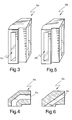
- FIG. 3 is an isometric view of a first embodiment of a ventilated body block according to the invention.
- FIG. 4 is a cross-sectional view of the ventilated body block of FIG. 3;
- FIG. 5 is an isometric view of a second embodiment of a ventilated body block according to the invention.
- FIG. 6 is a cross-sectional view of the ventilated body block of FIG. 5;
- FIG. 7 is a partial top plan view, partially sectioned, of the turns of a rotor end winding at one end of the rotor in accordance with an alternate embodiment of the invention.
- FIG. 8 is a view, similar to FIG. 7, of yet another alternate embodiment of the invention.
- a rotor body 10 is illustrated with a rotor end winding 12 extending beyond one end of the rotor body.
- the rotor end winding includes the end region of a number of complete coils 14 , 16 , 18 and 20 in a concentric, generally rectangular configuration.
- two such concentric sets of coils are arranged on opposite sides of the rotor.
- the invention is applicable, however, to other rotor configurations as well.
- Each coil includes many field turns 22 of copper conductors in a stacked configuration.
- These coils are nested within the radial slots 24 machined into the outer periphery of the rotor body, with the end windings extending axially beyond the rotor body at both ends of the machine in conventional fashion.
- a spindle portion 26 of the rotor extends in an axial direction, radially inward of the end winding.
- the coils 14 , 16 , 18 and 20 are supported in the slots 24 of the rotor body against centrifugal forces by metallic wedges (not shown) which bear against machined dovetail surfaces (not shown) in each rotor coil slot.
- the rotor winding is electrically insulated from the rotor body via appropriate slot armor 28 .
- turns which make up the coils of the rotor winding are electrically insulated from each other via appropriate turn-to-turn insulation.
- the insulation is not shown in the drawings.
- FIG. 1 one half of the end winding 12 is shown in simplified form. Spacer blocks that are normally present in the end winding to separate the coils 14 , 16 , 18 and 20 have been eliminated for clarity.
- Cooling gas passages are formed to extend along at least a portion of the length of at least one turn of at least one coil of the end winding.
- the cooling gas passages include first cooling gas passages defined by grooves 30 machined on the upper, and/or lower, radial face of some or all of the turns to allow cooling gas to enter respective ports 32 on one longitudinal side of the turns and to exit into the cavities 34 , 36 , and 38 between the coils 14 and 16 , 16 and 18 , and 18 and 20 , respectively, on the other longitudinal side of the turns.
- the turns of the coils in some rotors are formed from multiple layers.
- cooling gas passages for the purposes described herein may be defined by grooves in the upper and/or lower radial faces of one or more of the layers of one or more of the turns.
- Vent passages 40 such as curved vent slots are machined in the rotor body “teeth” (the solid portions between the radial slots 24 at the axial end of the rotor body, also referred to herein as the pole face). This allows the cooling gas that exits grooves 30 to flow via slots 40 into the annular air gap between the machine's stator (not shown) and the rotor body 10 .
- the curved vent slots 40 may be replaced by combinations of axially and radially extending holes.
- turns in coils 14 , 16 , 18 and 20 also have second cooling gas passages defined in the illustrated embodiments by longitudinal grooves 44 extending from holes or ports 42 close to the pole face to radial chimneys 46 within the rotor body 10 that are formed, e.g., by punching the turns 22 .
- cooling gas grooves 44 are longitudinally offset from grooves 30 , so that the act to cool respective portions of the turn(s).
- some of the cooling gas also flows axially within a sub-slot (not shown) in the rotor body that, in turn, communicates with additional radial chimneys (not shown) formed in the coils at axially spaced locations along the rotor body.
- chimneys 46 do not connect with the sub-slot (not shown), but the chimneys axially inboard thereof are connected to the sub-slot.
- chimneys 46 receive cooling gas only via grooves 44 in the field turns of the coils.
- the flow of cooling gas into slots 40 and through the cooling gas grooves 44 and chimneys 46 cools the transition section of the rotor and the coils between the end winding 12 and the rotor body 10 , referred to herein above as the sot end region.
- the cooling of the rotor body 10 itself can be achieved by any compatible method such as radial cooling (or axial/radial cooling) via cooling gas fed from sub-slots machined under the main coil slots in the rotor body, or any gap pickup body cooling scheme where cooling gas enters and discharges from the machine's air gap.
- the pumping head of the machine's rotor drives the cooling gas flow through the passages.
- the cooling gas flow distribution within the passages can be controlled via sizing of the ports, sizing of the punched holes in the turns which form the radial chimneys, sizing of the grooves, and the radial/axial alignment of the turns to insure that each turn in the section of the rotor end winding of interest is ventilated properly.
- each cavity space between adjacent coils has its own set of ‘exhaust’ ports 42 to feed slot or groove 44 .
- This provides for effective and uniform cooling of each of the coil side cavities 34 , 36 , and 38 with none of the coil side cavities left unvented.
- providing ports 42 for every cavity actively relieves hot pockets of trapped gas that might otherwise exist for unvented cavities, other than the limited gas exchanged from passively cooled trapped cavities.
- the flow pattern and flow distributions are more predictable and uniform which helps make the design more robust. It is to be noted and understood in this regard that gas flowing through the cavity on its way to port 42 additionally cools the sides of the copper coils and thus provides cooling in addition to that provided by gas flowing through grooves 30 and 44 .
- first gas passages or grooves 30 are defined in the radially upper and/or lower face of the copper turns of the coils.
- the ventilating/cooling gas inlet port for cooling the end winding region is schematically shown in at 32 .
- the inlet ports are inclined with respect to the exposed longitudinal side face of the turns, in this case also corresponding to the axial end face of the assembly. It is to be understood, however, that as an alternative to an inclined port, one or more of the inlet ports could be disposed perpendicular to the direction in which the groove 30 extends. In the illustrated embodiment a single groove extends along each half end winding to discharge through discharge port 48 .
- the exit or discharge port 48 is preferably inclined with respect to the side face of the respective copper turn.
- one or more of the exit ports may be disposed perpendicular to the side face of the turn.
- the exit ports will discharge the end winding ventilating gas into the cavities intermediate the coils.
- slots or holes 40 are defined in the rotor teeth for directing the end winding gas, e.g., to the gap between the rotor and the stator (not shown).
- ventilated body blocks 50 are provided to intercept flow from the exit ports 48 of the copper turns.
- each ventilated block 50 acts as a manifold for intercepting and directing this flow to the slots or holes in the rotor teeth.
- FIGS. 3 and 4 respectively are isometric and cross-sectional views of a ventilated body block 50 a according to one embodiment of the invention, having a generally curved flow passage 52 a.
- FIGS. 5 and 6 illustrate an alternate embodiment of a ventilated body block 50 b .
- this embodiment differs from the embodiment of FIGS. 3 and 4 in that the flow passage 52 b is generally straight.
- the particular configuration of the flow passage 52 through the ventilated block 50 is not critical to the implementation of the invention, it is to be understood that it is preferred for the passage(s) 52 defined through the ventilated body block be adapted to intercept the flow exiting the exit ports 48 and encourage its unimpeded flow to the slots or holes 40 in the rotor teeth for discharge to the air gap.
- the ventilated body blocks described above are provided for the purpose of isolating the hotter gas feeding the ventilation slots in the teeth from the cooler gas entering the next adjacent coil in the same vicinity. Thus, any leakage in the block is to be avoided as it will reduce the effectiveness of the cooling.
- the above-described two exemplary forms of the block solve this problem but provide for a relatively complex block construction.
- FIG. 1 shows all of the ports 48 coming from the right hand side, to open at the left face of the turns. As an alternative, these ports can all be defined as coming from the left hand side. With this alternate configuration, the cavity 54 at the rotor pole body would be vented via the ports to the chimney 46 of coil 14 , and there would be no need for a ventilation slot in the rotor pole. It is to be understood that other variations of blocking patterns can be adapted from this basic concept.
- the first embodiment of the invention contemplates a ventilation slot 40 in every rotor tooth.
- a ventilation slot 40 in every rotor tooth.
- the ventilation passages will increase the amount of machining time needed to process the rotor forging and will increase the set ups and operations thus potentially increasing the likelihood of a machining error.
- an alternate embodiment of the invention adopts a simplified construction of the ventilated body block and eliminates half of the ventilation slots contemplated in the rotor teeth.
- this alternate embodiment of the invention is accomplished by having the outlet ports 148 from two adjacent coils 114 , 116 and 118 , 120 feed a single ventilation slot 140 in the rotor teeth.
- the inlet ports 142 for two adjacent coils draw gas from the same cavity, e.g. cavity 136 , between the coils.
- the ventilated body block 150 can now possess left to right symmetry and may be simplified as compared to the first embodiment.
- FIG. 7 shows, by way of example, the slot end region of four coils.
- the first embodiment provided all of the inlet ports 42 on one side of the coil, the right side in the illustration of FIG. 1, and all of the end winding cooling groove outlet ports 48 on the opposite side, the left side of FIG.
- FIG. 7 pairs inlet ports 142 of two adjacent coils and outlet ports 148 of other adjacent coils. With this arrangement, pairs of outlet ports 148 feed the same ventilation slot 140 in the rotor teeth thereby eliminating the need for slot in line with cavities 136 that feed the inlet ports 142 . This isolation of the inlet ports from the outlet ports inherently eliminates the potential for hot gas leaking from one outlet port 148 and/or block 150 to the nearby inlet port.
- the body blocks between the coils now take two functions and forms.
- Those body blocks 156 adjacent the inlet ports 142 are now the same as the conventional spacer blocks and require no special machining.
- Those blocks 150 connecting the outlet ports 148 to the ventilation slots 140 in the teeth are now symmetric and the passage 152 therein can be formed by simple machining processes (drilling and milling).
- the first embodiment of the invention may require some machining in the rotor pole to form a ventilation slot or hole. This is because in at least two places in the rotor an outlet port 148 will feed into a ventilation slot that is on the same side of the coil 14 as the rotor pole. Thus, special steps would likely be required to machine the slots in the pole and suitable plates or other retention mechanism would be required to retain the ventilation block 50 in place at the outlet port 48 .
- the arrangement of the embodiment of FIG. 7 eliminates the need for a ventilation passage in the rotor pole and the block that feeds it. More particularly, because all common rotors use an even number of coil slots on each side of the pole, it would always possible to place the required ventilation slots in the teeth between the slots. As a result, current blocking arrangements in the pole region already in use could be retained without change.
- the arrangement of the second embodiment provides for an arrangement of inlet and outlet ports on the coils so as to eliminate the need for half of the ventilation slots in the rotor teeth, a simplification of the ventilated block to a more symmetrical form that may be easily machined, a reduction in the risk that hot gas from an outlet port will leak into an inlet port and elimination for the need for a ventilation slots in the rotor pole.
- this embodiment leaves the coil side cavities 134 and 138 between the two grooves 130 unvented and has two grooves 144 drawing cooling gas from the same cavity 136 . This configuration could thus tend toward non-uniform flow patterns, with trapped cavity and less effective surface area cooling.
- This also may introduce a leading side and trailing side (with respect to rotation) characteristic for exhaust ports 142 . The leading and trailing characteristic tends to force flow preferentially to one side which may also may lead to nonuniform coolings for the adjacent coils.
- FIG. 8 Yet another embodiment is illustrated in FIG. 8 .
- This embodiment incorporates a vent slot 140 in every other tooth for discharge of the coil cooling gas passages 130 and further provides for a discharge of gas from beneath the coils through cavity 258 formed by a slot 240 in the tooth and ventilated body block 256 disposed adjacent the cavity exhaust/cooling passage inlet port 142 .
- the remaining components of this embodiment correspond to those of the FIG. 7 embodiment and have been labeled accordingly. With this configuration, maximum use is made of every tooth in respect to providing for a uniform cooling of the rotor end and flow of ventilating gas.
- end winding cooling passage such as groove 30
- slot end region cooling passage such as groove 44
- these passages or grooves may be defined in either the upper or the lower face of the turn, or one in the upper face and one in the lower face of one or more turns.
- these grooves could be defined in alternating turns so that every other turn has a groove 30 and the remaining turns have a groove 44 .
- Other suitable cooling passage configurations and combinations will be apparent to the skilled artisan from the foregoing examples.
- the above described ventilation schemes can be employed on any machine with a concentric wound field winding of suitable turn dimensions with square corner and/or C-shaped corner construction, and can most readily be applied to two pole and four pole round rotor turbine driven generators.
- the cooling gas can be any suitable gas but is most typically air or hydrogen.
Landscapes
- Engineering & Computer Science (AREA)
- Power Engineering (AREA)
- Windings For Motors And Generators (AREA)
Abstract
Description
Claims (16)
Priority Applications (1)
| Application Number | Priority Date | Filing Date | Title |
|---|---|---|---|
| US09/496,727 US6339268B1 (en) | 2000-02-02 | 2000-02-02 | Cooling ventilation circuit for rotor end winding and slot end region cooling |
Applications Claiming Priority (1)
| Application Number | Priority Date | Filing Date | Title |
|---|---|---|---|
| US09/496,727 US6339268B1 (en) | 2000-02-02 | 2000-02-02 | Cooling ventilation circuit for rotor end winding and slot end region cooling |
Publications (1)
| Publication Number | Publication Date |
|---|---|
| US6339268B1 true US6339268B1 (en) | 2002-01-15 |
Family
ID=23973860
Family Applications (1)
| Application Number | Title | Priority Date | Filing Date |
|---|---|---|---|
| US09/496,727 Expired - Lifetime US6339268B1 (en) | 2000-02-02 | 2000-02-02 | Cooling ventilation circuit for rotor end winding and slot end region cooling |
Country Status (1)
| Country | Link |
|---|---|
| US (1) | US6339268B1 (en) |
Cited By (25)
| Publication number | Priority date | Publication date | Assignee | Title |
|---|---|---|---|---|
| US6392326B1 (en) * | 2000-12-22 | 2002-05-21 | General Electric Company | Flow-through spaceblocks with deflectors and method for increased electric generator endwinding cooling |
| US20020079784A1 (en) * | 2000-12-22 | 2002-06-27 | Salamah Samir Armando | Re-entrant spaceblock configuration for enhancing cavity flow in rotor endwinding of electric power generator |
| US6417586B1 (en) * | 2000-12-19 | 2002-07-09 | General Electric Company | Gas cooled endwindings for dynamoelectric machine rotor and endwinding cool method |
| US6452294B1 (en) * | 2000-12-19 | 2002-09-17 | General Electric Company | Generator endwinding cooling enhancement |
| US6465917B2 (en) * | 2000-12-19 | 2002-10-15 | General Electric Company | Spaceblock deflector for increased electric generator endwinding cooling |
| US6495943B2 (en) * | 2000-12-19 | 2002-12-17 | General Electric Company | Spaceblock scoops for enhanced rotor cavity heat transfer |
| US6628020B1 (en) | 2002-05-21 | 2003-09-30 | General Electric Company | Heat transfer enhancement of ventilation grooves of rotor end windings in dynamoelectric machines |
| US6680549B2 (en) | 2001-11-01 | 2004-01-20 | General Electric Company | Tapered rotor-stator air gap for superconducting synchronous machine |
| US6720687B2 (en) * | 2000-12-22 | 2004-04-13 | General Electric Company | Wake reduction structure for enhancing cavity flow in generator rotor endwindings |
| US6759770B1 (en) | 2003-04-11 | 2004-07-06 | General Electric Company | Cooling system for modular field windings of a generator |
| US6844637B1 (en) | 2003-08-13 | 2005-01-18 | Curtiss-Wright Electro-Mechanical Corporation | Rotor assembly end turn cooling system and method |
| US6870299B1 (en) | 2003-12-19 | 2005-03-22 | General Electric Company | Thermal management of rotor endwinding coils |
| US20050212379A1 (en) * | 2004-03-23 | 2005-09-29 | General Electric Company | Module winding system for electrical machines and methods of electrical connection |
| US6952070B1 (en) | 2004-04-29 | 2005-10-04 | General Electric Company | Capped flat end windings in an electrical machine |
| US6965185B1 (en) | 2004-05-26 | 2005-11-15 | General Electric Company | Variable pitch manifold for rotor cooling in an electrical machine |
| US20050258708A1 (en) * | 2004-05-21 | 2005-11-24 | General Electric Company | End winding restraint in an electrical machine |
| US20050264130A1 (en) * | 2004-05-26 | 2005-12-01 | General Electric Company | Apparatus and methods for anchoring a modular winding to a rotor in an electrical machine |
| US20050264129A1 (en) * | 2004-05-26 | 2005-12-01 | General Electric Company | Optimized drive train for a turbine driven electrical machine |
| US6977460B1 (en) | 2004-08-26 | 2005-12-20 | General Electric Company | Spacer for axial spacing enclosure rings and shields in an electrical machine |
| US6983607B2 (en) | 2003-10-22 | 2006-01-10 | General Electric Company | Turbine compartment ventilation control system and method using variable speed fan |
| US20090295239A1 (en) * | 2008-06-03 | 2009-12-03 | General Electric Company | Heat transfer enhancement of ventilation chimneys for dynamoelectric machine rotors |
| US20100045126A1 (en) * | 2005-10-18 | 2010-02-25 | Kenichi Hattori | Rotor of rotary-electric machine |
| US11108303B2 (en) | 2016-08-22 | 2021-08-31 | Ford Global Technologies, Llc | Electric machine end turn channels |
| CN114257009A (en) * | 2021-09-24 | 2022-03-29 | 中国科学院电工研究所 | Magnetic pole coil, rotor and salient pole motor with internal cooling structure |
| US20260066744A1 (en) * | 2022-08-29 | 2026-03-05 | General Electric Renovables España, S.L. | Cooling system for a superconducting generator |
Citations (14)
| Publication number | Priority date | Publication date | Assignee | Title |
|---|---|---|---|---|
| US1927890A (en) | 1930-12-19 | 1933-09-26 | Westinghouse Electric & Mfg Co | Ventilation of rotor end coils of turbogenerators |
| US2787721A (en) | 1954-01-19 | 1957-04-02 | Vickers Electrical Co Ltd | Dynamoelectric machines |
| US2833944A (en) | 1957-07-22 | 1958-05-06 | Gen Electric | Ventilation of end turn portions of generator rotor winding |
| US4315172A (en) * | 1978-12-14 | 1982-02-09 | Kraftwerk Union Aktiengesellschaft | Cooling system for rotors of electric machines, especially for turbo-generator rotors with a superconductive field winding |
| US4363982A (en) * | 1981-01-26 | 1982-12-14 | General Electric Company | Dual curved inlet gap pickup wedge |
| US4543503A (en) | 1983-12-20 | 1985-09-24 | General Electric Company | Ventilated end turns for rotor windings of a dynamoelectric machine |
| US4709177A (en) | 1986-06-30 | 1987-11-24 | General Electric Company | Ventilated end turns for rotor windings of a dynamoelectric machine |
| US4814655A (en) * | 1987-12-21 | 1989-03-21 | General Electric Company | Ventilated gusset for single-layer turns in a dynamoelectric machine |
| US5103552A (en) * | 1990-08-09 | 1992-04-14 | General Electric Company | Method of forming an integral water-cooled circuit ring bus bar assembly for high frequency generators |
| US5189325A (en) * | 1990-06-15 | 1993-02-23 | General Electric Company | Liquid cooling the rotor of an electrical machine |
| US5281877A (en) * | 1992-11-13 | 1994-01-25 | General Electric Company | Dynamoelectric machine rotor endwindings with corner cooling passages |
| US5644179A (en) * | 1994-12-19 | 1997-07-01 | General Electric Company | Gas cooled end turns for dynamoelectric machine rotor |
| US5652469A (en) * | 1994-06-16 | 1997-07-29 | General Electric Company | Reverse flow ventilation system with stator core center discharge duct and/or end region cooling system |
| US5929550A (en) * | 1997-03-20 | 1999-07-27 | General Electric Co. | Ventilated creepage blocks |
-
2000
- 2000-02-02 US US09/496,727 patent/US6339268B1/en not_active Expired - Lifetime
Patent Citations (14)
| Publication number | Priority date | Publication date | Assignee | Title |
|---|---|---|---|---|
| US1927890A (en) | 1930-12-19 | 1933-09-26 | Westinghouse Electric & Mfg Co | Ventilation of rotor end coils of turbogenerators |
| US2787721A (en) | 1954-01-19 | 1957-04-02 | Vickers Electrical Co Ltd | Dynamoelectric machines |
| US2833944A (en) | 1957-07-22 | 1958-05-06 | Gen Electric | Ventilation of end turn portions of generator rotor winding |
| US4315172A (en) * | 1978-12-14 | 1982-02-09 | Kraftwerk Union Aktiengesellschaft | Cooling system for rotors of electric machines, especially for turbo-generator rotors with a superconductive field winding |
| US4363982A (en) * | 1981-01-26 | 1982-12-14 | General Electric Company | Dual curved inlet gap pickup wedge |
| US4543503A (en) | 1983-12-20 | 1985-09-24 | General Electric Company | Ventilated end turns for rotor windings of a dynamoelectric machine |
| US4709177A (en) | 1986-06-30 | 1987-11-24 | General Electric Company | Ventilated end turns for rotor windings of a dynamoelectric machine |
| US4814655A (en) * | 1987-12-21 | 1989-03-21 | General Electric Company | Ventilated gusset for single-layer turns in a dynamoelectric machine |
| US5189325A (en) * | 1990-06-15 | 1993-02-23 | General Electric Company | Liquid cooling the rotor of an electrical machine |
| US5103552A (en) * | 1990-08-09 | 1992-04-14 | General Electric Company | Method of forming an integral water-cooled circuit ring bus bar assembly for high frequency generators |
| US5281877A (en) * | 1992-11-13 | 1994-01-25 | General Electric Company | Dynamoelectric machine rotor endwindings with corner cooling passages |
| US5652469A (en) * | 1994-06-16 | 1997-07-29 | General Electric Company | Reverse flow ventilation system with stator core center discharge duct and/or end region cooling system |
| US5644179A (en) * | 1994-12-19 | 1997-07-01 | General Electric Company | Gas cooled end turns for dynamoelectric machine rotor |
| US5929550A (en) * | 1997-03-20 | 1999-07-27 | General Electric Co. | Ventilated creepage blocks |
Cited By (33)
| Publication number | Priority date | Publication date | Assignee | Title |
|---|---|---|---|---|
| US6465917B2 (en) * | 2000-12-19 | 2002-10-15 | General Electric Company | Spaceblock deflector for increased electric generator endwinding cooling |
| US6495943B2 (en) * | 2000-12-19 | 2002-12-17 | General Electric Company | Spaceblock scoops for enhanced rotor cavity heat transfer |
| US6417586B1 (en) * | 2000-12-19 | 2002-07-09 | General Electric Company | Gas cooled endwindings for dynamoelectric machine rotor and endwinding cool method |
| US6452294B1 (en) * | 2000-12-19 | 2002-09-17 | General Electric Company | Generator endwinding cooling enhancement |
| US6617749B2 (en) * | 2000-12-22 | 2003-09-09 | General Electric Company | Re-entrant spaceblock configuration for enhancing cavity flow in rotor endwinding of electric power generator |
| US20020079784A1 (en) * | 2000-12-22 | 2002-06-27 | Salamah Samir Armando | Re-entrant spaceblock configuration for enhancing cavity flow in rotor endwinding of electric power generator |
| US6720687B2 (en) * | 2000-12-22 | 2004-04-13 | General Electric Company | Wake reduction structure for enhancing cavity flow in generator rotor endwindings |
| US6392326B1 (en) * | 2000-12-22 | 2002-05-21 | General Electric Company | Flow-through spaceblocks with deflectors and method for increased electric generator endwinding cooling |
| US6680549B2 (en) | 2001-11-01 | 2004-01-20 | General Electric Company | Tapered rotor-stator air gap for superconducting synchronous machine |
| US6628020B1 (en) | 2002-05-21 | 2003-09-30 | General Electric Company | Heat transfer enhancement of ventilation grooves of rotor end windings in dynamoelectric machines |
| US6759770B1 (en) | 2003-04-11 | 2004-07-06 | General Electric Company | Cooling system for modular field windings of a generator |
| US6844637B1 (en) | 2003-08-13 | 2005-01-18 | Curtiss-Wright Electro-Mechanical Corporation | Rotor assembly end turn cooling system and method |
| US6983607B2 (en) | 2003-10-22 | 2006-01-10 | General Electric Company | Turbine compartment ventilation control system and method using variable speed fan |
| US6870299B1 (en) | 2003-12-19 | 2005-03-22 | General Electric Company | Thermal management of rotor endwinding coils |
| EP1544979A3 (en) * | 2003-12-19 | 2006-05-17 | General Electric Company | Thermal management of rotor endwinding coils |
| US6989621B2 (en) | 2004-03-23 | 2006-01-24 | General Electric Company | Module winding system for electrical machines and methods of electrical connection |
| US20050212379A1 (en) * | 2004-03-23 | 2005-09-29 | General Electric Company | Module winding system for electrical machines and methods of electrical connection |
| US6952070B1 (en) | 2004-04-29 | 2005-10-04 | General Electric Company | Capped flat end windings in an electrical machine |
| US6972507B1 (en) | 2004-05-21 | 2005-12-06 | General Electric Company | End winding restraint in an electrical machine |
| US20050258708A1 (en) * | 2004-05-21 | 2005-11-24 | General Electric Company | End winding restraint in an electrical machine |
| US20050264128A1 (en) * | 2004-05-26 | 2005-12-01 | General Electric Company | Variable pitch manifold for rotor cooling in an electrical machine |
| US6977459B1 (en) | 2004-05-26 | 2005-12-20 | General Electric Company | Apparatus and methods for anchoring a modular winding to a rotor in an electrical machine |
| US6965185B1 (en) | 2004-05-26 | 2005-11-15 | General Electric Company | Variable pitch manifold for rotor cooling in an electrical machine |
| US20050264130A1 (en) * | 2004-05-26 | 2005-12-01 | General Electric Company | Apparatus and methods for anchoring a modular winding to a rotor in an electrical machine |
| US20050264129A1 (en) * | 2004-05-26 | 2005-12-01 | General Electric Company | Optimized drive train for a turbine driven electrical machine |
| US7078845B2 (en) | 2004-05-26 | 2006-07-18 | General Electric Company | Optimized drive train for a turbine driven electrical machine |
| US6977460B1 (en) | 2004-08-26 | 2005-12-20 | General Electric Company | Spacer for axial spacing enclosure rings and shields in an electrical machine |
| US20100045126A1 (en) * | 2005-10-18 | 2010-02-25 | Kenichi Hattori | Rotor of rotary-electric machine |
| US7893574B2 (en) * | 2005-10-18 | 2011-02-22 | Hitachi, Ltd. | Rotor of rotary-electric machine |
| US20090295239A1 (en) * | 2008-06-03 | 2009-12-03 | General Electric Company | Heat transfer enhancement of ventilation chimneys for dynamoelectric machine rotors |
| US11108303B2 (en) | 2016-08-22 | 2021-08-31 | Ford Global Technologies, Llc | Electric machine end turn channels |
| CN114257009A (en) * | 2021-09-24 | 2022-03-29 | 中国科学院电工研究所 | Magnetic pole coil, rotor and salient pole motor with internal cooling structure |
| US20260066744A1 (en) * | 2022-08-29 | 2026-03-05 | General Electric Renovables España, S.L. | Cooling system for a superconducting generator |
Similar Documents
| Publication | Publication Date | Title |
|---|---|---|
| US6339268B1 (en) | Cooling ventilation circuit for rotor end winding and slot end region cooling | |
| EP1171938B1 (en) | Direct gas cooled endwinding ventilation schemes for machines with concentric coil rotors | |
| EP1171937B1 (en) | Direct gas cooled longitudinal/cross-flow endwinding ventilation schemes for machines with concentric coil rotors | |
| KR101755669B1 (en) | Heat transfer enhancement of dynamoelectric machine rotors | |
| US4739207A (en) | Wedge locking device in a radially ventilated rotor | |
| US6956313B2 (en) | Method and apparatus for reducing hot spot temperatures on stacked field windings | |
| US8629589B2 (en) | Dynamoelectric machine coil spacerblock having flow deflecting channel in coil facing surface thereof | |
| KR100854197B1 (en) | Gas cooled generator machine and endwinding cooling method | |
| KR100467388B1 (en) | Spaceblock deflector for increased electric generator endwinding cooling | |
| KR100467389B1 (en) | Gas cooled endwindings for dynamoelectric machine rotor and endwinding cooling method | |
| KR100851098B1 (en) | Spaceblock scoops for enhanced rotor cavity heat transfer | |
| KR100467390B1 (en) | Wake reduction structure for enhancing cavity flow in generator rotor endwindings | |
| JPH10285853A (en) | Rotating electric machine rotor | |
| US7342345B2 (en) | Paddled rotor spaceblocks | |
| US20120080967A1 (en) | Dynamoelectric machine coil spaceblock having flow deflecting structure in coil facing surface thereof | |
| US6952070B1 (en) | Capped flat end windings in an electrical machine | |
| US7541714B2 (en) | Streamlined body wedge blocks and method for enhanced cooling of generator rotor | |
| EP2246963A2 (en) | Dynamoelectric Machine Coil Spaceblock Having Flow Deflecting Structure in Coil Facing Surface Thereof | |
| KR20090126205A (en) | Ventilation chimneys with improved heat transfer for rotors of dynamoelectric machines |
Legal Events
| Date | Code | Title | Description |
|---|---|---|---|
| AS | Assignment |
Owner name: GENERAL ELECTRIC COMPANY, NEW YORK Free format text: ASSIGNMENT OF ASSIGNORS INTEREST;ASSIGNORS:KAMINSKI, CHRISTOPHER ANTHONY;JARCZNSKI, EMIL DONALD;BOARDMAN, IV, WILLIAM H.;AND OTHERS;REEL/FRAME:010803/0944;SIGNING DATES FROM 20000428 TO 20000517 |
|
| AS | Assignment |
Owner name: GENERAL ELECTRIC COMPANY, NEW YORK Free format text: ASSIGNMENT OF ASSIGNORS INTEREST;ASSIGNORS:KAMINSKI, CHRISTOPHER ANTHONY;JARCZYNSKI, EMIL DONALD;BOARDMAN, WILLIAM H. IV;AND OTHERS;REEL/FRAME:010997/0370 Effective date: 20000517 |
|
| FEPP | Fee payment procedure |
Free format text: PAYOR NUMBER ASSIGNED (ORIGINAL EVENT CODE: ASPN); ENTITY STATUS OF PATENT OWNER: LARGE ENTITY |
|
| STCF | Information on status: patent grant |
Free format text: PATENTED CASE |
|
| FPAY | Fee payment |
Year of fee payment: 4 |
|
| SULP | Surcharge for late payment | ||
| REMI | Maintenance fee reminder mailed | ||
| FPAY | Fee payment |
Year of fee payment: 8 |
|
| SULP | Surcharge for late payment |
Year of fee payment: 7 |
|
| FPAY | Fee payment |
Year of fee payment: 12 |