US6324744B1 - Method of mounting and axially aligning an engine accessory - Google Patents
Method of mounting and axially aligning an engine accessory Download PDFInfo
- Publication number
- US6324744B1 US6324744B1 US09/563,898 US56389800A US6324744B1 US 6324744 B1 US6324744 B1 US 6324744B1 US 56389800 A US56389800 A US 56389800A US 6324744 B1 US6324744 B1 US 6324744B1
- Authority
- US
- United States
- Prior art keywords
- accessory
- bushing
- engine
- elongated member
- bushings
- Prior art date
- Legal status (The legal status is an assumption and is not a legal conclusion. Google has not performed a legal analysis and makes no representation as to the accuracy of the status listed.)
- Expired - Lifetime
Links
Images


Classifications
-
- H—ELECTRICITY
- H02—GENERATION; CONVERSION OR DISTRIBUTION OF ELECTRIC POWER
- H02K—DYNAMO-ELECTRIC MACHINES
- H02K5/00—Casings; Enclosures; Supports
- H02K5/26—Means for adjusting casings relative to their supports
-
- F—MECHANICAL ENGINEERING; LIGHTING; HEATING; WEAPONS; BLASTING
- F02—COMBUSTION ENGINES; HOT-GAS OR COMBUSTION-PRODUCT ENGINE PLANTS
- F02F—CYLINDERS, PISTONS OR CASINGS, FOR COMBUSTION ENGINES; ARRANGEMENTS OF SEALINGS IN COMBUSTION ENGINES
- F02F7/00—Casings, e.g. crankcases
- F02F7/0043—Arrangements of mechanical drive elements
- F02F7/0046—Shape of casings adapted to facilitate fitting or dismantling of engine parts
-
- F—MECHANICAL ENGINEERING; LIGHTING; HEATING; WEAPONS; BLASTING
- F16—ENGINEERING ELEMENTS AND UNITS; GENERAL MEASURES FOR PRODUCING AND MAINTAINING EFFECTIVE FUNCTIONING OF MACHINES OR INSTALLATIONS; THERMAL INSULATION IN GENERAL
- F16H—GEARING
- F16H7/00—Gearings for conveying rotary motion by endless flexible members
- F16H7/08—Means for varying tension of belts, ropes or chains
- F16H7/10—Means for varying tension of belts, ropes or chains by adjusting the axis of a pulley
- F16H7/14—Means for varying tension of belts, ropes or chains by adjusting the axis of a pulley of a driving or driven pulley
-
- Y—GENERAL TAGGING OF NEW TECHNOLOGICAL DEVELOPMENTS; GENERAL TAGGING OF CROSS-SECTIONAL TECHNOLOGIES SPANNING OVER SEVERAL SECTIONS OF THE IPC; TECHNICAL SUBJECTS COVERED BY FORMER USPC CROSS-REFERENCE ART COLLECTIONS [XRACs] AND DIGESTS
- Y10—TECHNICAL SUBJECTS COVERED BY FORMER USPC
- Y10T—TECHNICAL SUBJECTS COVERED BY FORMER US CLASSIFICATION
- Y10T29/00—Metal working
- Y10T29/49—Method of mechanical manufacture
- Y10T29/49826—Assembling or joining
- Y10T29/49947—Assembling or joining by applying separate fastener
- Y10T29/49948—Multipart cooperating fastener [e.g., bolt and nut]
-
- Y—GENERAL TAGGING OF NEW TECHNOLOGICAL DEVELOPMENTS; GENERAL TAGGING OF CROSS-SECTIONAL TECHNOLOGIES SPANNING OVER SEVERAL SECTIONS OF THE IPC; TECHNICAL SUBJECTS COVERED BY FORMER USPC CROSS-REFERENCE ART COLLECTIONS [XRACs] AND DIGESTS
- Y10—TECHNICAL SUBJECTS COVERED BY FORMER USPC
- Y10T—TECHNICAL SUBJECTS COVERED BY FORMER US CLASSIFICATION
- Y10T29/00—Metal working
- Y10T29/49—Method of mechanical manufacture
- Y10T29/49826—Assembling or joining
- Y10T29/49947—Assembling or joining by applying separate fastener
- Y10T29/49959—Nonresilient fastener
-
- Y—GENERAL TAGGING OF NEW TECHNOLOGICAL DEVELOPMENTS; GENERAL TAGGING OF CROSS-SECTIONAL TECHNOLOGIES SPANNING OVER SEVERAL SECTIONS OF THE IPC; TECHNICAL SUBJECTS COVERED BY FORMER USPC CROSS-REFERENCE ART COLLECTIONS [XRACs] AND DIGESTS
- Y10—TECHNICAL SUBJECTS COVERED BY FORMER USPC
- Y10T—TECHNICAL SUBJECTS COVERED BY FORMER US CLASSIFICATION
- Y10T29/00—Metal working
- Y10T29/49—Method of mechanical manufacture
- Y10T29/49826—Assembling or joining
- Y10T29/49947—Assembling or joining by applying separate fastener
- Y10T29/49963—Threaded fastener
-
- Y—GENERAL TAGGING OF NEW TECHNOLOGICAL DEVELOPMENTS; GENERAL TAGGING OF CROSS-SECTIONAL TECHNOLOGIES SPANNING OVER SEVERAL SECTIONS OF THE IPC; TECHNICAL SUBJECTS COVERED BY FORMER USPC CROSS-REFERENCE ART COLLECTIONS [XRACs] AND DIGESTS
- Y10—TECHNICAL SUBJECTS COVERED BY FORMER USPC
- Y10T—TECHNICAL SUBJECTS COVERED BY FORMER US CLASSIFICATION
- Y10T29/00—Metal working
- Y10T29/49—Method of mechanical manufacture
- Y10T29/49826—Assembling or joining
- Y10T29/49947—Assembling or joining by applying separate fastener
- Y10T29/49966—Assembling or joining by applying separate fastener with supplemental joining
-
- Y—GENERAL TAGGING OF NEW TECHNOLOGICAL DEVELOPMENTS; GENERAL TAGGING OF CROSS-SECTIONAL TECHNOLOGIES SPANNING OVER SEVERAL SECTIONS OF THE IPC; TECHNICAL SUBJECTS COVERED BY FORMER USPC CROSS-REFERENCE ART COLLECTIONS [XRACs] AND DIGESTS
- Y10—TECHNICAL SUBJECTS COVERED BY FORMER USPC
- Y10T—TECHNICAL SUBJECTS COVERED BY FORMER US CLASSIFICATION
- Y10T403/00—Joints and connections
- Y10T403/32—Articulated members
- Y10T403/32606—Pivoted
- Y10T403/32861—T-pivot, e.g., wrist pin, etc.
- Y10T403/32918—T-pivot, e.g., wrist pin, etc. fork and tongue
- Y10T403/32926—T-pivot, e.g., wrist pin, etc. fork and tongue with interposed antifriction means
Definitions
- This invention relates to the use of mounts for engine accessories and more particularly to a new and improved method of mounting an accessory which facilitates axial aligning the accessory.
- the mounting arrangement of this invention utilizes a pivotal lower mount assembly with two spaced arm portions having apertures therethrough in which a pair of press fitting bushings extend.
- a single fastener such as a threaded bolt extends through the two bushings and through a corresponding passage in the accessory which is positioned between the two arm portions.
- one bushing is internally threaded to mesh with threads on the bolt and provision is made to eliminate rotation of the bushing and thus a need for an assembly tool such as a wrench to prevent rotation of the bushing during assembly.
- the accessory is pivoted about the single fastener of the lower mount so that another fastener can be utilized to firmly attach the accessory to the engine.
- This invention can be used to mount a variety of components particularly where additional remote mountings are used in conjunction with the mounting provided by this invention.
- the mounting arrangement provides a self-locking and self aligning function prior to finally securing the accessory to the engine.
- the mount arrangement employs non-rotatable, axially sliding bushings that adjust axially to accommodate tolerance stack-up variations between the arms of the mount and the corresponding attachment structure of the accessory. Turning of the mounts single connecting bolt which extends through the mount arms and the attachment structure creates forces which axially move the bushings toward one another and against the engine's mount structure. This axial movement clamps and secures the accessory to the bushings and to the engine attachment structure.
- the accessory can be pivoted and moved in an axial direction to position the accessory for final attachment to the engine by means of a fastener, such as a cap screw.
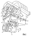
- FIG. 1 is a pictorial view of a bottom portion of an internal combustion engine with an engine driven air compressor mounted thereto;
- FIG. 2 is an enlarged cross sectioned view of a part of an aligning and locking mount assembly attaching the air conditioner compressor to the engine taken generally along sight lines 2 — 2 of FIG. 1;
- FIG. 2 a is a sectioned view of part of the mounting assembly shown in FIG. 2 in which the connection bolt is in its pre-assembled position of the mount assembly:
- FIG. 3 is an enlarged pictorial view of a first bushing used in the aligning and locking mount assembly of FIGS. 2 and 2 a ;
- FIG. 4 is an enlarged pictorial view of a second bushing used in the aligning and locking mount assembly of FIGS. 2 and 2 a ;
- FIG. 5 is a pictorial view similar to FIG. 1 but showing the attachment of upper arm portions of the air conditioning compressor to the engine;
- FIG. 6 is an end view of the engine of FIG. 1 illustrating another view of the attachment of the air conditioning compressor to the engine by the mounting assembly and by the upper attachment arms;
- FIG. 7 is a pictorial view of another embodiment of the invention illustrated by an accessory with integral mounting attachment arms that incorporate the features of the separate aligning and locking mount component shown in FIGS. 1 - 6 .
- FIG. 1 an accessory in the form of air conditioning compressor 10 having an input drive pulley 12 on the outboard end thereof conventionally driven by the engine crankshaft mounted pulley 13 through a serpentine drive belt 14 .
- the compressor 10 is shown in a partially assembled condition operatively connected to the engine by a lower mount assembly 16 .
- the compressor 10 is mounted to the engine's oil pan 20 by mount assembly 16 .
- the oil pan 20 in turn is attached to the engine block 22 of the vehicle engine 24 by screws 26 .
- a gasket 28 is interposed between the oil pan 20 and the engine block 22 to effect fluid sealing between these two components.
- FIGS. 5 and 6 the compressor 10 has been pivoted (counterclockwise in FIG. 6) to the final assembly position for connection to the engine block 22 .
- This connection is in addition to the connection provided by the lower mount assembly 16 to the oil pan 20 .
- a pair of laterally spaced upper arms 30 and 32 of the compressor are directly attached to engine block 22 by fastener screws 34 .
- These upper arms 30 , 32 extend outwardly from opposite end portions of the compressor housing and are attached at their distal ends by the screws 34 which are adapted to thread into the internally threaded and laterally spaced bores 36 and 38 formed in the engine block 22 at remote points from the lower mount assembly 16 .
- the design of the lower mount assembly is required to automatically compensate for limit stack (quantity production variation in parts tolerance) between the engine components and also between oil pan positioning and the anchor points by which the lower mount is attached to the accessory.
- the lower mount assembly 16 has a generally rectilinear attachment or base frame 40 which has a pair of laterally extending attachment wings 42 located on opposite ends of the base 40 .
- wings 42 have aligned fastener openings 43 formed therein which align with threaded openings 44 formed in corresponding radically extending lug portions 46 of the housing of the compressor 10 .
- Threaded fasteners 48 extend through the openings 43 in the wing portions and are threaded into the corresponding openings 44 in the lug portions 46 . This securely couples the mount assembly 16 to compressor 10 .
- a pair of laterally spaced apart attachment arms 50 , 52 of base frame 40 project away from and upwardly in FIG. 1 .
- the arms 50 , 52 of base frame 40 have cylindrical and axially aligned through-passages 54 , 56 .
- These passages respectively receive split bushings 58 and 60 which are press fitted in the passages 54 , 56 .
- the bushings are sized to frictionally fit in their passages so that they will not turn after being press fitted therein.
- Bushings 58 , 60 may be conveniently made from powdered metal.
- Bushing 58 has a generally cylindrically and tubular body 62 which extends axially from an enlarged and circular head portion 64 .
- the body 62 and head portion 64 are split lengthwise by a longitudinal slit 66 allowing it to readily accommodate a range of diameters of passages 54 .
- the inner diameter cylindrical surface 67 of bushing 58 is preferably cylindrical and smooth and has a dimension sufficient to accommodate passage of the cylindrical shank 70 of a connector bolt 72 therethrough as seen in FIGS. 2 and 2A.
- the other bushing 60 is generally like bushing 58 and has a cylindrical tubular body 74 and a contact head portion 76 . As with bushing 58 , the bushing 60 has a longitudinal slit 78 therein to create a tight press fit of the bushing in various diametered openings such as passage 56 . Thus bushing 60 is held in passage by its natural recovery force exerted outwardly against the walls of the passage.
- the body 74 of bushing 60 is internally threaded with a helical thread 80 for meshing with a corresponding thread on the end portion 82 of the bolt 72 .
- the head portion 76 of bushing 60 also has a radially outwardly extending protuberance or tab 84 .
- Tab 85 is designed to physically contact a raised stop 86 extending upward from the upper surface of the base 40 of the lower mount 16 . This contact prevents rotation of the internally threaded bushing 60 as the bolt 72 is rotated from the pre-assembly position of FIG. 2A to the assembled position of FIG. 2 .
- the bushings 58 , 60 are axially moved toward one another into a position where the head portions 64 , 76 engage the compressor housing.
- the oil pan 20 is an aluminum casting formed with an integral and projecting accessory anchor portion 90 .
- the anchor portion 90 includes a pair of laterally spaced and outwardly projecting attachment arms 92 , 94 .
- the arms 92 , 94 have aligned openings 96 , 98 of sufficient diameter to allow the shank 70 of bolt 72 to pass readily therethrough.
- the outboard side surfaces 100 , 102 of arms 92 , 94 are flattened for optimizing physical contact with the correspondingly flattened outer surfaces 104 , 106 on the bushings 58 , 60 when in a fully clamped and locked position assembled condition.
- the accessory mount assembly 16 is pre-installed on the compressor 10 so that its laterally spaced arms 50 , 52 can then be conveniently positioned to straddle the arm portions 92 , 94 of the anchor portion 90 of the oil pan 20 .
- bushings 58 and 60 are inserted into the passages 54 , 56 and separated by a sufficient distance to accommodate a wide tolerance in the dimension of the anchor portion 90 of the oil pan.
- the enlarged polygonal head 110 of the bolt is turned by suitable tooling, such as a torque wrench to advance the bolt 72 into the threaded bushing 60 .
- suitable tooling such as a torque wrench
- the flattened side 112 of the bolt head engages the end 114 of bushing 58
- the resultant inwardly directed force F-R of the bolt on the bushing 58 moves it to the right in FIG. 2 A.
- the threaded connection of bolt 72 and bushing 60 creates an inwardly directed pulling force F-L on bushing 60 causing its movement to the left in FIG. 2 A.
- bushings While the bushings are moved toward one another, they are inhibited from rotation in their associated passages 54 , 56 by the press-fit therein. Also, the entry of the screw section of the bolt 72 into the corresponding threaded portion of bushing 60 creates a radial expansion effect which creates gripping force between bushing 60 and arm 52 to further secure this bushing against rotation.
- bushings 58 , 60 results in positioning of the compressor structure and self-alignment relative to the anchor portion 90 located between the spaced arm portions 50 , 52 of the mount assembly 16 .
- the compressor 10 Once the compressor 10 fixed by engagement of the ends of bushing 58 , 60 with the anchor portion, they are positioned in a desired axial operating position relative to the anchor.
- the outboard pulley portion 12 is aligned with the associated pulley 13 on the engine's crankshaft. This makes for a smooth transfer of driving power through the serpentine belt 14 .
- the arm portions 50 , 52 of mount 16 are not subjected to bending forces which might fractured them of otherwise damage them. This is because the clamping forces are routed through the bushings 58 , 60 and on to the opposing side surfaces 100 , 102 of the rigid anchor arms 92 , 94 .
- FIG. 2 The clamping and locking action shown in FIG. 2 is accomplished subsequent to the initial connection of the mount 16 to the anchor portion 90 as seen in FIG. 2 A.
- the accessory or compressor 10 can then be pivoted counterclockwise about the axis of bolt 72 to the final assembled position shown in FIGS. 5 and 6.
- the fasteners 34 can be removed and the compressor 10 can then be pivoted clockwise in FIG. 6 to a more accessible position.
- the axial position of the compressor 10 can be adjusted by axial shifting of the bushings 58 , 60 in passages 54 , 56 before the compressor is firmly attached to the engine block 22 by fasteners 34 extending through apertures in upper arms 30 , 32 and into treaded openings 36 , 38 .
- the bolt 72 is then be tightened to a desired torque which completes the mounting operation of the compressor 10 to the engine.
- threaded bushing 60 is inhibited from rotation in passage 56 by interaction between tab 84 and raised portion 86 .
- FIG. 7 illustrates a modification of the invention in which the locking mount assembly includes laterally spaced arm portions 200 , 202 which are integrally formed from the accessory or compressor housing 204 .
- the associated bushings and other componentry of the mount arrangement remain substantially the same as in the previously described embodiment. If desired, these bushings could be keyed or splinted into the arms 200 , 202 to allow their clamping action while preventing their rotation.
Landscapes
- Engineering & Computer Science (AREA)
- General Engineering & Computer Science (AREA)
- Mechanical Engineering (AREA)
- Power Engineering (AREA)
- Chemical & Material Sciences (AREA)
- Combustion & Propulsion (AREA)
- Connection Of Plates (AREA)
Abstract
Description
Claims (6)
Priority Applications (1)
| Application Number | Priority Date | Filing Date | Title |
|---|---|---|---|
| US09/563,898 US6324744B1 (en) | 2000-05-03 | 2000-05-03 | Method of mounting and axially aligning an engine accessory |
Applications Claiming Priority (1)
| Application Number | Priority Date | Filing Date | Title |
|---|---|---|---|
| US09/563,898 US6324744B1 (en) | 2000-05-03 | 2000-05-03 | Method of mounting and axially aligning an engine accessory |
Publications (1)
| Publication Number | Publication Date |
|---|---|
| US6324744B1 true US6324744B1 (en) | 2001-12-04 |
Family
ID=24252328
Family Applications (1)
| Application Number | Title | Priority Date | Filing Date |
|---|---|---|---|
| US09/563,898 Expired - Lifetime US6324744B1 (en) | 2000-05-03 | 2000-05-03 | Method of mounting and axially aligning an engine accessory |
Country Status (1)
| Country | Link |
|---|---|
| US (1) | US6324744B1 (en) |
Cited By (19)
| Publication number | Priority date | Publication date | Assignee | Title |
|---|---|---|---|---|
| US6460823B1 (en) * | 1999-12-29 | 2002-10-08 | Visteon Global Technologies, Inc. | Movable mounting lug for a compressor |
| US6513478B2 (en) * | 2000-08-25 | 2003-02-04 | Honda Giken Kogyo Kabushiki Kaisha | Generator mounting arrangement for vertical engines and outboard marine drives |
| US6609491B2 (en) * | 2000-09-26 | 2003-08-26 | Honda Giken Kogyo Kabushiki Kaisha | Multi-cylinder engine and engine auxiliary parts mounting construction |
| EP1557930A1 (en) * | 2004-01-23 | 2005-07-27 | Peugeot Citroen Automobiles | Fixing device for a rotating machine on a vehicle motor |
| DE102004041044A1 (en) * | 2004-08-25 | 2006-03-02 | Ina-Schaeffler Kg | Pivot bearing of an aggregate |
| US20060049706A1 (en) * | 2004-09-07 | 2006-03-09 | Mitsubishi Denki Kabushiki Kaisha | On-vehicle generator mounting device |
| WO2007031687A1 (en) * | 2005-09-13 | 2007-03-22 | Renault S.A.S. | Device for fixing a motor vehicle element on the vehicle engine |
| US20080028603A1 (en) * | 2006-07-20 | 2008-02-07 | Go Takegawa | Motorcycle engine |
| WO2009087477A3 (en) * | 2007-12-21 | 2009-10-08 | Toyota Jidosha Kabushiki Kaisha | Bracket fastening structure |
| US7717080B1 (en) | 2005-02-08 | 2010-05-18 | Billet Specialties, Inc. | Serpentine belt system |
| US20100181146A1 (en) * | 2007-06-13 | 2010-07-22 | Mann+Hummel Gmbh | Oil Pan for Internal Combustion Engine Transmission Unit |
| US20110081996A1 (en) * | 2009-10-02 | 2011-04-07 | Thermo King Corporation | Belt drive system assembly and tension apparatus |
| DE102005006063B4 (en) * | 2005-02-10 | 2013-10-10 | Schaeffler Technologies AG & Co. KG | Pivot bearing for a rotatably mounted, used as a clamping system accessory, in particular a generator clamping system |
| US8591136B2 (en) * | 2010-05-27 | 2013-11-26 | Agusta S.P.A. | Non-rotating universal joint for a helicopter drive unit |
| US20140062050A1 (en) * | 2012-08-29 | 2014-03-06 | Williams-Bayer Industries, LLC | Sleeve, Sub-Assembly, Vehicular Suspension Assembly And Methods For Forming/Assembling The Same |
| US20170244307A1 (en) * | 2014-10-27 | 2017-08-24 | Toyota Jidosha Kabushiki Kaisha | Electric apparatus |
| US10683828B2 (en) * | 2016-12-02 | 2020-06-16 | Cummins Inc. | Mounting bracket |
| US10927725B2 (en) * | 2015-10-29 | 2021-02-23 | Cummins Inc. | Two plane accessory mounting with sliding pilot interface |
| US11391359B2 (en) * | 2016-09-20 | 2022-07-19 | Carrier Corporation | Tool for use with a belted sheave system and method of use |
Citations (17)
| Publication number | Priority date | Publication date | Assignee | Title |
|---|---|---|---|---|
| US2937040A (en) * | 1957-01-07 | 1960-05-17 | Silentbloc | Flexible couplings for axially aligned, pivotally connected members |
| US3018667A (en) | 1958-02-20 | 1962-01-30 | Chrysler Corp | Belt tightener |
| US3362243A (en) | 1967-02-14 | 1968-01-09 | Hunt Foods And Ind Inc | Engine cooling fan assembly |
| US3730147A (en) | 1971-10-29 | 1973-05-01 | Gen Motors Corp | Engine accessory arrangement |
| US4221982A (en) * | 1978-07-31 | 1980-09-09 | General Motors Corporation | Liquid cooled rectified-alternating current generator |
| WO1982003735A1 (en) * | 1981-04-09 | 1982-10-28 | Ikegami Takashi | Charging generator |
| US4633828A (en) | 1985-06-03 | 1987-01-06 | Steele Luther R | Adjustable polar point mount |
| US4808023A (en) * | 1985-02-12 | 1989-02-28 | The United States Of America As Represented By The Secretary Of The Air Force | Dual load path pin clevis joint |
| US4835428A (en) * | 1987-09-29 | 1989-05-30 | Mitsubishi Denki Kabushiki Kaisha | Setting device for vehicle generator |
| US4849665A (en) * | 1987-02-26 | 1989-07-18 | Mitsubishi Denki Kabushiki Kaisha | Anti-vibration mounting for vehicle alternator |
| US4899703A (en) * | 1987-12-07 | 1990-02-13 | Automobiles Peugeot | Device for fastening a first part such as an accessory to a second part such as a support with a bush for eliminating the assembling backlash between the two parts and bush used for the fastening of these parts |
| GB2240585A (en) * | 1989-12-29 | 1991-08-07 | Bosch Gmbh Robert | Swivel mounting for electric machines |
| US5065713A (en) | 1990-04-02 | 1991-11-19 | Seats William R | Mounting brackets for mounting engine asseccories |
| US5219138A (en) * | 1991-10-08 | 1993-06-15 | General Motors Corporation | Mounting bracket |
| US5269662A (en) * | 1992-07-14 | 1993-12-14 | Denton John W | Aircraft air conditioner compressor drive and mounting apparatus |
| JPH06317176A (en) * | 1993-05-10 | 1994-11-15 | Honda Motor Co Ltd | Auxiliary machine mounting structure of internal combustion engine |
| JPH08205464A (en) * | 1995-01-26 | 1996-08-09 | Hitachi Ltd | Auxiliary equipment mounting structure to the engine |
-
2000
- 2000-05-03 US US09/563,898 patent/US6324744B1/en not_active Expired - Lifetime
Patent Citations (17)
| Publication number | Priority date | Publication date | Assignee | Title |
|---|---|---|---|---|
| US2937040A (en) * | 1957-01-07 | 1960-05-17 | Silentbloc | Flexible couplings for axially aligned, pivotally connected members |
| US3018667A (en) | 1958-02-20 | 1962-01-30 | Chrysler Corp | Belt tightener |
| US3362243A (en) | 1967-02-14 | 1968-01-09 | Hunt Foods And Ind Inc | Engine cooling fan assembly |
| US3730147A (en) | 1971-10-29 | 1973-05-01 | Gen Motors Corp | Engine accessory arrangement |
| US4221982A (en) * | 1978-07-31 | 1980-09-09 | General Motors Corporation | Liquid cooled rectified-alternating current generator |
| WO1982003735A1 (en) * | 1981-04-09 | 1982-10-28 | Ikegami Takashi | Charging generator |
| US4808023A (en) * | 1985-02-12 | 1989-02-28 | The United States Of America As Represented By The Secretary Of The Air Force | Dual load path pin clevis joint |
| US4633828A (en) | 1985-06-03 | 1987-01-06 | Steele Luther R | Adjustable polar point mount |
| US4849665A (en) * | 1987-02-26 | 1989-07-18 | Mitsubishi Denki Kabushiki Kaisha | Anti-vibration mounting for vehicle alternator |
| US4835428A (en) * | 1987-09-29 | 1989-05-30 | Mitsubishi Denki Kabushiki Kaisha | Setting device for vehicle generator |
| US4899703A (en) * | 1987-12-07 | 1990-02-13 | Automobiles Peugeot | Device for fastening a first part such as an accessory to a second part such as a support with a bush for eliminating the assembling backlash between the two parts and bush used for the fastening of these parts |
| GB2240585A (en) * | 1989-12-29 | 1991-08-07 | Bosch Gmbh Robert | Swivel mounting for electric machines |
| US5065713A (en) | 1990-04-02 | 1991-11-19 | Seats William R | Mounting brackets for mounting engine asseccories |
| US5219138A (en) * | 1991-10-08 | 1993-06-15 | General Motors Corporation | Mounting bracket |
| US5269662A (en) * | 1992-07-14 | 1993-12-14 | Denton John W | Aircraft air conditioner compressor drive and mounting apparatus |
| JPH06317176A (en) * | 1993-05-10 | 1994-11-15 | Honda Motor Co Ltd | Auxiliary machine mounting structure of internal combustion engine |
| JPH08205464A (en) * | 1995-01-26 | 1996-08-09 | Hitachi Ltd | Auxiliary equipment mounting structure to the engine |
Cited By (32)
| Publication number | Priority date | Publication date | Assignee | Title |
|---|---|---|---|---|
| US6460823B1 (en) * | 1999-12-29 | 2002-10-08 | Visteon Global Technologies, Inc. | Movable mounting lug for a compressor |
| US6513478B2 (en) * | 2000-08-25 | 2003-02-04 | Honda Giken Kogyo Kabushiki Kaisha | Generator mounting arrangement for vertical engines and outboard marine drives |
| US6609491B2 (en) * | 2000-09-26 | 2003-08-26 | Honda Giken Kogyo Kabushiki Kaisha | Multi-cylinder engine and engine auxiliary parts mounting construction |
| EP1557930A1 (en) * | 2004-01-23 | 2005-07-27 | Peugeot Citroen Automobiles | Fixing device for a rotating machine on a vehicle motor |
| FR2865583A1 (en) * | 2004-01-23 | 2005-07-29 | Peugeot Citroen Automobiles Sa | DEVICE FOR SOLIDARIZING A ROTATING MACHINE ON A VEHICLE ENGINE. |
| DE102004041044A1 (en) * | 2004-08-25 | 2006-03-02 | Ina-Schaeffler Kg | Pivot bearing of an aggregate |
| US20060049706A1 (en) * | 2004-09-07 | 2006-03-09 | Mitsubishi Denki Kabushiki Kaisha | On-vehicle generator mounting device |
| JP2006081242A (en) * | 2004-09-07 | 2006-03-23 | Mitsubishi Electric Corp | Vehicle generator mounting device |
| US7119466B2 (en) * | 2004-09-07 | 2006-10-10 | Mitsubishi Denki Kabushiki Kaisha | On-vehicle generator mounting device |
| US7717080B1 (en) | 2005-02-08 | 2010-05-18 | Billet Specialties, Inc. | Serpentine belt system |
| US8028671B1 (en) | 2005-02-08 | 2011-10-04 | Billet Specialties, Inc. | Serpentine belt system |
| DE102005006063B4 (en) * | 2005-02-10 | 2013-10-10 | Schaeffler Technologies AG & Co. KG | Pivot bearing for a rotatably mounted, used as a clamping system accessory, in particular a generator clamping system |
| WO2007031687A1 (en) * | 2005-09-13 | 2007-03-22 | Renault S.A.S. | Device for fixing a motor vehicle element on the vehicle engine |
| US7627949B2 (en) * | 2006-07-20 | 2009-12-08 | Special Parts Takegawa Co., Ltd. | Motorcycle engine |
| US20080028603A1 (en) * | 2006-07-20 | 2008-02-07 | Go Takegawa | Motorcycle engine |
| US20100181146A1 (en) * | 2007-06-13 | 2010-07-22 | Mann+Hummel Gmbh | Oil Pan for Internal Combustion Engine Transmission Unit |
| US8347844B2 (en) * | 2007-06-13 | 2013-01-08 | Mann + Hummel Gmbh | Oil pan for internal combustion engine transmission unit |
| US8499883B2 (en) | 2007-12-21 | 2013-08-06 | Toyota Jidosha Kabushiki Kaisha | Bracket fastening structure |
| WO2009087477A3 (en) * | 2007-12-21 | 2009-10-08 | Toyota Jidosha Kabushiki Kaisha | Bracket fastening structure |
| US20100269780A1 (en) * | 2007-12-21 | 2010-10-28 | Toyota Jidosha Kabushiki Kaisha | Bracket fastening structure |
| CN101903634B (en) * | 2007-12-21 | 2013-04-24 | 丰田自动车株式会社 | Bracket connection structure |
| US8506435B2 (en) | 2009-10-02 | 2013-08-13 | Thermo King Corporation | Belt drive system assembly and tension apparatus |
| US20110081999A1 (en) * | 2009-10-02 | 2011-04-07 | Thermo King Corporation | Belt drive system assembly and tension apparatus |
| US8512183B2 (en) | 2009-10-02 | 2013-08-20 | Thermo King Corporation | Belt drive system assembly and tension apparatus |
| US20110081996A1 (en) * | 2009-10-02 | 2011-04-07 | Thermo King Corporation | Belt drive system assembly and tension apparatus |
| US8591136B2 (en) * | 2010-05-27 | 2013-11-26 | Agusta S.P.A. | Non-rotating universal joint for a helicopter drive unit |
| US20140062050A1 (en) * | 2012-08-29 | 2014-03-06 | Williams-Bayer Industries, LLC | Sleeve, Sub-Assembly, Vehicular Suspension Assembly And Methods For Forming/Assembling The Same |
| US8720920B2 (en) * | 2012-08-29 | 2014-05-13 | Williams-Bayer Industries Inc. | Sleeve, sub-assembly, vehicular suspension assembly and methods for forming/assembling the same |
| US20170244307A1 (en) * | 2014-10-27 | 2017-08-24 | Toyota Jidosha Kabushiki Kaisha | Electric apparatus |
| US10927725B2 (en) * | 2015-10-29 | 2021-02-23 | Cummins Inc. | Two plane accessory mounting with sliding pilot interface |
| US11391359B2 (en) * | 2016-09-20 | 2022-07-19 | Carrier Corporation | Tool for use with a belted sheave system and method of use |
| US10683828B2 (en) * | 2016-12-02 | 2020-06-16 | Cummins Inc. | Mounting bracket |
Similar Documents
| Publication | Publication Date | Title |
|---|---|---|
| US6324744B1 (en) | Method of mounting and axially aligning an engine accessory | |
| US6360712B1 (en) | Self-aligning and locking mount for engine accessory | |
| US5716154A (en) | Attachment device | |
| US9249714B2 (en) | Method and device for fastening an exhaust gas converter module | |
| EP0179772A1 (en) | Alternator mounting assembly | |
| CN103032500B (en) | Extension spring mounting mechanism | |
| CA2501169A1 (en) | Tolerance compensating mounting device | |
| JP2004521276A (en) | Apparatus for elastically supporting a hydraulic unit of a vehicle brake system to a vehicle | |
| WO2018135990A1 (en) | A suspension device | |
| US20180355646A1 (en) | Vehicle hood hinge | |
| CA2444933A1 (en) | Tolerance compensating mounting device | |
| TW202413193A (en) | Drive unit of a vehicle which can be operated by muscle power and/or motor power | |
| US7096845B1 (en) | Captured nut using a stamped retention feature | |
| US20120247420A1 (en) | Assembly with adjustable compression load limiter | |
| US20070057422A1 (en) | Device for vibration-damping disposition of a unit, and unit equipped with such devices | |
| US20220407195A1 (en) | Battery terminal | |
| US5865067A (en) | Pedal mounting structure and method of installing a pedal in an automotive vehicle | |
| US20040086353A1 (en) | Bolt and method of retaining a bolt to an engine component | |
| US11703179B2 (en) | Bracket for aligning a compressor to an engine | |
| US5123314A (en) | Engine rotate tool | |
| US7946794B2 (en) | Quick fastening nut | |
| US7600735B2 (en) | Sliding clip to retain a captured nut | |
| CN114430874A (en) | Fixing system for modular antenna | |
| US20080240852A1 (en) | Maintaining Device For Fixing A Motor Vehicle Assembly | |
| CN113795398B (en) | Equipment support device in vehicle |
Legal Events
| Date | Code | Title | Description |
|---|---|---|---|
| AS | Assignment |
Owner name: DAIMLERCHRYSLER CORP., MICHIGAN Free format text: ASSIGNMENT OF ASSIGNORS INTEREST;ASSIGNORS:BANKS, THOMAS M.;CHUANG, VEM L.;WHEAT, KENNETH W.;REEL/FRAME:010813/0043 Effective date: 20000501 |
|
| STCF | Information on status: patent grant |
Free format text: PATENTED CASE |
|
| FPAY | Fee payment |
Year of fee payment: 4 |
|
| AS | Assignment |
Owner name: WILMINGTON TRUST COMPANY, DELAWARE Free format text: GRANT OF SECURITY INTEREST IN PATENT RIGHTS - FIRST PRIORITY;ASSIGNOR:CHRYSLER LLC;REEL/FRAME:019773/0001 Effective date: 20070803 Owner name: WILMINGTON TRUST COMPANY,DELAWARE Free format text: GRANT OF SECURITY INTEREST IN PATENT RIGHTS - FIRST PRIORITY;ASSIGNOR:CHRYSLER LLC;REEL/FRAME:019773/0001 Effective date: 20070803 |
|
| AS | Assignment |
Owner name: WILMINGTON TRUST COMPANY, DELAWARE Free format text: GRANT OF SECURITY INTEREST IN PATENT RIGHTS - SECOND PRIORITY;ASSIGNOR:CHRYSLER LLC;REEL/FRAME:019767/0810 Effective date: 20070803 Owner name: WILMINGTON TRUST COMPANY,DELAWARE Free format text: GRANT OF SECURITY INTEREST IN PATENT RIGHTS - SECOND PRIORITY;ASSIGNOR:CHRYSLER LLC;REEL/FRAME:019767/0810 Effective date: 20070803 |
|
| AS | Assignment |
Owner name: DAIMLERCHRYSLER COMPANY LLC, MICHIGAN Free format text: CHANGE OF NAME;ASSIGNOR:DAIMLERCHRYSLER CORPORATION;REEL/FRAME:021779/0793 Effective date: 20070329 |
|
| AS | Assignment |
Owner name: CHRYSLER LLC, MICHIGAN Free format text: CHANGE OF NAME;ASSIGNOR:DAIMLERCHRYSLER COMPANY LLC;REEL/FRAME:021826/0001 Effective date: 20070727 |
|
| AS | Assignment |
Owner name: US DEPARTMENT OF THE TREASURY, DISTRICT OF COLUMBI Free format text: GRANT OF SECURITY INTEREST IN PATENT RIGHTS - THIR;ASSIGNOR:CHRYSLER LLC;REEL/FRAME:022259/0188 Effective date: 20090102 Owner name: US DEPARTMENT OF THE TREASURY,DISTRICT OF COLUMBIA Free format text: GRANT OF SECURITY INTEREST IN PATENT RIGHTS - THIR;ASSIGNOR:CHRYSLER LLC;REEL/FRAME:022259/0188 Effective date: 20090102 Owner name: US DEPARTMENT OF THE TREASURY, DISTRICT OF COLUMBIA Free format text: GRANT OF SECURITY INTEREST IN PATENT RIGHTS - THIR;ASSIGNOR:CHRYSLER LLC;REEL/FRAME:022259/0188 Effective date: 20090102 |
|
| FPAY | Fee payment |
Year of fee payment: 8 |
|
| AS | Assignment |
Owner name: CHRYSLER LLC, MICHIGAN Free format text: RELEASE BY SECURED PARTY;ASSIGNOR:US DEPARTMENT OF THE TREASURY;REEL/FRAME:022902/0310 Effective date: 20090608 Owner name: CHRYSLER LLC,MICHIGAN Free format text: RELEASE BY SECURED PARTY;ASSIGNOR:US DEPARTMENT OF THE TREASURY;REEL/FRAME:022902/0310 Effective date: 20090608 |
|
| AS | Assignment |
Owner name: CHRYSLER LLC, MICHIGAN Free format text: RELEASE OF SECURITY INTEREST IN PATENT RIGHTS - FIRST PRIORITY;ASSIGNOR:WILMINGTON TRUST COMPANY;REEL/FRAME:022910/0498 Effective date: 20090604 Owner name: CHRYSLER LLC, MICHIGAN Free format text: RELEASE OF SECURITY INTEREST IN PATENT RIGHTS - SECOND PRIORITY;ASSIGNOR:WILMINGTON TRUST COMPANY;REEL/FRAME:022910/0740 Effective date: 20090604 Owner name: NEW CARCO ACQUISITION LLC, MICHIGAN Free format text: ASSIGNMENT OF ASSIGNORS INTEREST;ASSIGNOR:CHRYSLER LLC;REEL/FRAME:022915/0001 Effective date: 20090610 Owner name: THE UNITED STATES DEPARTMENT OF THE TREASURY, DIST Free format text: SECURITY AGREEMENT;ASSIGNOR:NEW CARCO ACQUISITION LLC;REEL/FRAME:022915/0489 Effective date: 20090610 Owner name: CHRYSLER LLC,MICHIGAN Free format text: RELEASE OF SECURITY INTEREST IN PATENT RIGHTS - FIRST PRIORITY;ASSIGNOR:WILMINGTON TRUST COMPANY;REEL/FRAME:022910/0498 Effective date: 20090604 Owner name: CHRYSLER LLC,MICHIGAN Free format text: RELEASE OF SECURITY INTEREST IN PATENT RIGHTS - SECOND PRIORITY;ASSIGNOR:WILMINGTON TRUST COMPANY;REEL/FRAME:022910/0740 Effective date: 20090604 Owner name: NEW CARCO ACQUISITION LLC,MICHIGAN Free format text: ASSIGNMENT OF ASSIGNORS INTEREST;ASSIGNOR:CHRYSLER LLC;REEL/FRAME:022915/0001 Effective date: 20090610 Owner name: THE UNITED STATES DEPARTMENT OF THE TREASURY,DISTR Free format text: SECURITY AGREEMENT;ASSIGNOR:NEW CARCO ACQUISITION LLC;REEL/FRAME:022915/0489 Effective date: 20090610 Owner name: THE UNITED STATES DEPARTMENT OF THE TREASURY, DISTRICT OF COLUMBIA Free format text: SECURITY AGREEMENT;ASSIGNOR:NEW CARCO ACQUISITION LLC;REEL/FRAME:022915/0489 Effective date: 20090610 |
|
| AS | Assignment |
Owner name: CHRYSLER GROUP LLC, MICHIGAN Free format text: CHANGE OF NAME;ASSIGNOR:NEW CARCO ACQUISITION LLC;REEL/FRAME:022919/0126 Effective date: 20090610 Owner name: CHRYSLER GROUP LLC,MICHIGAN Free format text: CHANGE OF NAME;ASSIGNOR:NEW CARCO ACQUISITION LLC;REEL/FRAME:022919/0126 Effective date: 20090610 |
|
| AS | Assignment |
Owner name: CHRYSLER GROUP GLOBAL ELECTRIC MOTORCARS LLC, NORTH DAKOTA Free format text: RELEASE BY SECURED PARTY;ASSIGNOR:THE UNITED STATES DEPARTMENT OF THE TREASURY;REEL/FRAME:026343/0298 Effective date: 20110524 Owner name: CHRYSLER GROUP GLOBAL ELECTRIC MOTORCARS LLC, NORT Free format text: RELEASE BY SECURED PARTY;ASSIGNOR:THE UNITED STATES DEPARTMENT OF THE TREASURY;REEL/FRAME:026343/0298 Effective date: 20110524 Owner name: CHRYSLER GROUP LLC, MICHIGAN Free format text: RELEASE BY SECURED PARTY;ASSIGNOR:THE UNITED STATES DEPARTMENT OF THE TREASURY;REEL/FRAME:026343/0298 Effective date: 20110524 |
|
| AS | Assignment |
Owner name: CITIBANK, N.A., NEW YORK Free format text: SECURITY AGREEMENT;ASSIGNOR:CHRYSLER GROUP LLC;REEL/FRAME:026404/0123 Effective date: 20110524 |
|
| AS | Assignment |
Owner name: CITIBANK, N.A., NEW YORK Free format text: SECURITY AGREEMENT;ASSIGNOR:CHRYSLER GROUP LLC;REEL/FRAME:026435/0652 Effective date: 20110524 |
|
| FPAY | Fee payment |
Year of fee payment: 12 |
|
| AS | Assignment |
Owner name: JPMORGAN CHASE BANK, N.A., ILLINOIS Free format text: SECURITY AGREEMENT;ASSIGNOR:CHRYSLER GROUP LLC;REEL/FRAME:032384/0640 Effective date: 20140207 |
|
| AS | Assignment |
Owner name: FCA US LLC, MICHIGAN Free format text: CHANGE OF NAME;ASSIGNOR:CHRYSLER GROUP LLC;REEL/FRAME:035553/0356 Effective date: 20141203 |
|
| AS | Assignment |
Owner name: FCA US LLC, FORMERLY KNOWN AS CHRYSLER GROUP LLC, MICHIGAN Free format text: RELEASE OF SECURITY INTEREST RELEASING SECOND-LIEN SECURITY INTEREST PREVIOUSLY RECORDED AT REEL 026426 AND FRAME 0644, REEL 026435 AND FRAME 0652, AND REEL 032384 AND FRAME 0591;ASSIGNOR:CITIBANK, N.A.;REEL/FRAME:037784/0001 Effective date: 20151221 Owner name: FCA US LLC, FORMERLY KNOWN AS CHRYSLER GROUP LLC, Free format text: RELEASE OF SECURITY INTEREST RELEASING SECOND-LIEN SECURITY INTEREST PREVIOUSLY RECORDED AT REEL 026426 AND FRAME 0644, REEL 026435 AND FRAME 0652, AND REEL 032384 AND FRAME 0591;ASSIGNOR:CITIBANK, N.A.;REEL/FRAME:037784/0001 Effective date: 20151221 |
|
| AS | Assignment |
Owner name: FCA US LLC (FORMERLY KNOWN AS CHRYSLER GROUP LLC), Free format text: RELEASE BY SECURED PARTY;ASSIGNOR:CITIBANK, N.A.;REEL/FRAME:042885/0255 Effective date: 20170224 Owner name: FCA US LLC (FORMERLY KNOWN AS CHRYSLER GROUP LLC), MICHIGAN Free format text: RELEASE BY SECURED PARTY;ASSIGNOR:CITIBANK, N.A.;REEL/FRAME:042885/0255 Effective date: 20170224 |
|
| AS | Assignment |
Owner name: FCA US LLC (FORMERLY KNOWN AS CHRYSLER GROUP LLC), Free format text: RELEASE BY SECURED PARTY;ASSIGNOR:JPMORGAN CHASE BANK, N.A.;REEL/FRAME:048177/0356 Effective date: 20181113 Owner name: FCA US LLC (FORMERLY KNOWN AS CHRYSLER GROUP LLC), MICHIGAN Free format text: RELEASE BY SECURED PARTY;ASSIGNOR:JPMORGAN CHASE BANK, N.A.;REEL/FRAME:048177/0356 Effective date: 20181113 |