US6322176B1 - Transmission media patch panel modular cabinetry system - Google Patents
Transmission media patch panel modular cabinetry system Download PDFInfo
- Publication number
- US6322176B1 US6322176B1 US09/222,608 US22260898A US6322176B1 US 6322176 B1 US6322176 B1 US 6322176B1 US 22260898 A US22260898 A US 22260898A US 6322176 B1 US6322176 B1 US 6322176B1
- Authority
- US
- United States
- Prior art keywords
- closet
- patch
- transmission media
- module
- upright
- Prior art date
- Legal status (The legal status is an assumption and is not a legal conclusion. Google has not performed a legal analysis and makes no representation as to the accuracy of the status listed.)
- Expired - Fee Related
Links
Images


Classifications
-
- H—ELECTRICITY
- H04—ELECTRIC COMMUNICATION TECHNIQUE
- H04Q—SELECTING
- H04Q1/00—Details of selecting apparatus or arrangements
- H04Q1/02—Constructional details
- H04Q1/06—Cable ducts or mountings specially adapted for exchange installations
- H04Q1/064—Cable ducts or mountings specially adapted for exchange installations horizontal management arrangements
-
- H—ELECTRICITY
- H04—ELECTRIC COMMUNICATION TECHNIQUE
- H04Q—SELECTING
- H04Q1/00—Details of selecting apparatus or arrangements
- H04Q1/02—Constructional details
- H04Q1/06—Cable ducts or mountings specially adapted for exchange installations
- H04Q1/062—Cable ducts or mountings specially adapted for exchange installations vertical management arrangements
-
- H—ELECTRICITY
- H04—ELECTRIC COMMUNICATION TECHNIQUE
- H04Q—SELECTING
- H04Q1/00—Details of selecting apparatus or arrangements
- H04Q1/02—Constructional details
- H04Q1/13—Patch panels for monitoring, interconnecting or testing circuits, e.g. patch bay, patch field or jack field; Patching modules
-
- H—ELECTRICITY
- H04—ELECTRIC COMMUNICATION TECHNIQUE
- H04Q—SELECTING
- H04Q2201/00—Constructional details of selecting arrangements
- H04Q2201/02—Details of frames
Definitions
- the present invention relates to patch panels for communications use and, more particularly, to modular cabinetry for mounting patch panels thereto.
- various transmission media typically are connected to each other and to incoming and outgoing lines by means, such as connectors, which are mounted to patch panels.
- Patch panels generally are mounted within a communications closet, such as to a wall or other mounting surface, and incorporate a series of connectors for interconnecting the various transmission media.
- Transmission media such as copper wires formed into patch cord cordage, for instance, often incorporate plugs at their ends that are configured for mating with, for example, the plug-receiving cavities of jacks, which commonly serve as patch panel mounted connectors.
- the cordage of the patch cord typically extends away from the patch panel jack and tends to hang downwardly in front of the patch panel.
- these cords appear neat and orderly and can facilitate efficient patching efforts by a technician, because the patch cords and their associated jacks are readily accessible.
- a general appearance of disorder can result as the cordage of the patch cords inherently tend to form loops in front of the patch panel.
- the patch cords may become entangled or snarled with adjacent cords, thereby potentially hindering a technician's patching efforts.
- the present invention generally is directed to a transmission media patch panel modular cabinetry system for interconnecting various transmission media.
- the patch panel system incorporates at least one patch panel and two or more closet modules mounted to the patch panel.
- the closet modules provide cordage raceways, formed adjacent the patch panels, that are configured to pass transmission media therethrough.
- the raceways are hidden behind doors which selectively provide access to the cordage.
- the cabinetry system incorporates a minimal number of components which can be interconnected to form various configurations of patch panel arrays depending on the particular application.
- closet modules of the system can be arranged in various configurations, including, but not limited to: side-by-side configurations, which can be wall mounted or freestanding; and back-to-back configurations, which typically are freestanding.
- Some embodiments also can incorporate upper closet modules disposed above a patch panel, lower closet modules disposed below a patch panel, or both, with the upper and lower modules providing troughs for placing the slack portion of patch cord cordage therein.
- closet modules and their associated patch panels can be arranged in arrays of modules with the arrays being spaced from each other.
- These embodiments typically are freestanding and can incorporate cable cross bridges for supporting transmission media extending between the arrays.
- a preferred method aspect of the invention includes the steps of: providing a patch panel with a plurality of jacks mounted thereto, each of the jacks being configured to mate with a patch cord; providing first and second duplicate closet modules, with each of the closet modules incorporating an upright member, each of the upright members including first and second side walls and access channels formed therebetween, with each of the access channels sized and shaped to pass transmission media therethrough; arranging the first and second duplicate closet modules in an upright orientation; attaching the patch panel to the first closet module so that the first side wall of the first closet module engages the patch panel; inverting the second closet module, and; attaching the patch panel to the second closet module so that the first side wall of the second closet module engages the patch panel.
- FIG. 1 is a perspective view of a preferred embodiment of the transmission media patch panel modular cabinetry system of the present invention
- FIG. 2 is a front view of a preferred embodiment of the present invention
- FIG. 3 is a partially cut-away, cross-sectional view of the embodiment of FIG. 2 taken along section line 3 — 3 ;
- FIG. 4 is a partially cut-away, cross-sectional view of the embodiment of FIG. 2 taken along section line 4 — 4 ;
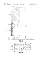
- FIG. 5 is a partially cut-away, cross-sectional view of the embodiment of FIG. 2 taken along section line 5 — 5 ;
- FIG. 6 is a partially cut-away, cross-sectional view of the embodiment of FIG. 2 taken along section line 6 — 6 ;
- FIG. 7 is a partially cut-away, cross-sectional view of the embodiment of FIG. 2 taken along section line 7 — 7 , and;
- FIG. 8 is a partially cut-away, front view of the embodiment of FIG. 2 shown with the door of the lower trough module in an open position.
- FIG. 1 depicts a preferred embodiment of the transmission media patch panel modular cabinetry system 10 of the present invention which provides a centralized location for the intersection and interconnection of various transmission media, such as cables 12 .
- the system 10 is formed by a plurality of cabinet modules, including individual or end closet modules 14 , dual closet modules 16 , lower trough module 18 and upper trough module 20 which interconnect to form various configurations of patch panel arrays. So configured, the system 10 incorporates a minimal number of components, thereby promoting potential cost savings relating to manufacture and implementation of the system.
- modules 14 , 16 , 18 , and 20 can cooperate to form a freestanding framework for mounting patch panels 22 and for encasing the various cords and cables used in association with the patch panels.
- a preferred embodiment of the system 10 incorporates one or more patch panel arrays 24 with each array including one or more patch panels 22 arranged in side-by-side relationship with one another.
- Each patch panel incorporates one or more jacks (not shown) which are configured to mate with the plugs of patch cords.
- the arrays typically are arranged in a spaced relationship, thereby forming a technician walkway 26 between opposing arrays.
- each array 24 can incorporate two or more opposing and outwardly facing patch panels 22 , such that each pair of the panels 22 are arranged in a back-to-back orientation.
- one or more cordage cross bridges 30 can be provided.
- the bridges 30 provide support surfaces for the cordage which span walkway 26 between the arrays so that the arrays may be electrically interconnected.
- the bridges 30 may be arranged at numerous locations, preferred embodiments incorporate the bridges 30 at the upper most portions of the arrays 24 , i.e. at the top of upper trough modules 20 , so that any cables 12 or cordage extending from one array to an adjacent array across the upper surface of the bridges 30 are placed outside of the walkway 26 .
- a single-sided array 24 incorporating patch panels 22 facing in a single direction can be provided for mounting to a mounting surface, such as a wall.
- the single-sided array 24 is mounted to the mounting surface in a conventional manner, such as by fastening the array to the mounting surface with mechanical fasteners.
- FIG. 2 a representative portion of an array 24 is shown in order that the modular construction of the array may be described in greater detail. It should be understood, however, that the embodiment of FIG. 2 is representative of both a panel array which is arranged in a freestanding configuration or in a wall mounted configuration, as described hereinbefore. Additionally, although only one array 24 is depicted in FIG. 2, the modular construction of the present invention allows for numerous system configurations, i.e. arrays incorporating more than one dual closet module 16 , which are also well within the scope of the invention.
- each array 24 incorporates one or more panel modules 32 .
- Each panel module 32 incorporates one or more patch panels 22 depending on the particular application, with the panels 22 capable of being arranged in various configurations within the array, such as side-by-side, top-to-bottom, staggered, etc.
- Each panel module 32 also incorporates at least one closet module 14 , and lower and upper trough modules 18 and 20 , respectively. Additionally, when two or more panel modules 32 cooperate to form an array 24 , a dual closet module 16 typically is disposed between each of the panel modules 32 .
- closet modules 14 and 16 each provide a vertical raceway 34 through which patch cords may pass while interconnecting the various panel components.
- the lower and upper trough modules, 18 and 20 respectively, provide horizontal raceways or slack troughs 36 (FIGS. 6 and 7 ), thereby providing space within the panel system 10 for organizing and, otherwise, hiding the various system cables and cords.
- Each vertical raceway 34 preferably includes one or more cord restraint brackets 38 for limiting the horizontal movement of cordage within the raceways 34 , thereby reducing the tendency of the cordage to snarl or entangle with other cordage within the raceway.
- Each of the modules can incorporate a door for providing access to the raceways and troughs and which is hingedly mounted to its respective module.
- each door is biased to a closed position, such as with a spring tensioner, among others, and is provided with a latch for selectively securing the door in its closed position.
- Each door preferably incorporates a handle.
- the aforementioned cord restraint brackets 38 also enable the closing of a module door without damaging a patch cord by preventing the cordage of a patch cord from improperly aligning within the raceway.
- the primary structural support component of closet module 14 A is upright member 46 , preferably a length of C-channel beam formed of steel, aluminum, or other various materials possessing suitable strength characteristics, i.e. a standard free-standing equipment rack, a standard wall-mount equipment rack, etc.
- Upright 46 includes opposing side walls 48 and 50 which extend outwardly from base 52 .
- side wall 48 are utilized as a mounting member through which fasteners (not shown) such as screws, bolts, etc. are be passed for attaching the closet module to a mounting surface.
- closet module 14 When, however, closet module 14 is arranged in a free-standing back-to-back configuration with an additional closet module 14 , the respective side walls 48 of each closet module are fastened together.
- a standard double-sided free-standing equipment rack (not shown) can be utilized, such that each of the modules 14 incorporate the standard double-sided free-standing equipment rack as a structural support.
- side wall 50 is attached to one or more patch panels 22 such that the front side of the panel, e.g. the side providing access to the jacks, faces away from the side wall 50 .
- a vertical raceway 34 is formed within closet module 14 and is defined by a series of walls, e.g. side wall 54 , back wall 56 , and end wall 58 , which cooperate to at least partially encase the raceway.
- the walls 54 , 56 and 58 can be formed as separate members which are joined together in a conventional manner such as by gluing, welding, etc. In the preferred embodiment of FIG. 3, however, the walls are formed from a single piece of sheet material, i.e. sheet metal, which is bent and formed to an appropriate shape.
- Shaped gussets 60 can be mounted, in some embodiments, at the corner joints of the walls for additional support.
- a door 40 also can be provided which normally closes opening 62 and, when opened, selectively provides access to the cables contained therein.
- the door is formed as a pressed panel typically being constructed of sheet metal; however, numerous other construction techniques and materials may be utilized.
- the door is typically hingedly attached at the front of end wall 58 , such as with a piano hinge or other conventional means, so that the door opens outwardly and away from the patch panel 22 as it swings through an angle ( ⁇ 14 ) of approximately 90°.
- Door 40 preferably incorporate a latch for selectively securing the door in its closed position.
- Raceway 34 can incorporate a vertically spaced series of cordage constraint brackets 64 for retaining cordage and cables within the raceway.
- Preferred embodiments of constrain bracket 64 incorporate an L-shaped member which extends from end wall 58 in a direction substantially parallel to back wall 56 and then extends substantially parallel to end wall 58 until they intersect and are mounted to back wall 56 . So configured, the L-shaped portion of each bracket 64 cooperates with the end and back walls to limit the horizontal movement of the cables.
- each constrain bracket 64 is formed as a full rectangular shaped bracket which mounts within the raceway 34 , although numerous other configurations also may be utilized.
- each upright 46 can incorporate one or more passages (not shown) therethrough thereby providing additional access ports for cables and cords.
- a dual closet module 16 is incorporated into a panel array 24 at a location where two modules of the panel system 10 meet in an abutting relationship.
- Dual closet module 16 is structurally supported by a pair of uprights 46 which are preferably formed as a length of C-channel beam. Uprights 46 typically are oriented so that their respective side walls 48 and 50 extend away from each other.
- a dual closet module 16 is to be mounted to a mounting surface, such as a wall, mounting of the module is facilitated by fastening side walls 48 to the mounting surface.
- each of the raceways 34 being bounded, at least in part, by side walls 54 , back walls 56 and end walls 58 .
- end walls 58 function as partitions, with the walls 58 preferably being fastened to one another by means, such as conventional fasteners, in order to maintain the side-by-side orientation of the raceways 34 .
- Module 16 also can incorporate cordage constraint brackets 64 which can be attached to walls 54 , 56 and/or 58 .
- end walls 58 preferably incorporate one or more passthrough openings 68 which are each sized and shaped for passing patch cords therethrough.
- Each passthrough opening 68 includes a grommet 70 formed of suitable insulating material for electrically isolating any patch cords passing through opening 68 from the side walls. Additionally, any joints formed between side walls 54 and back walls 56 , and the joints formed between back walls 56 and end walls 58 can be reinforced by shaped gussets 60 .
- preferred embodiments of the dual closet module 16 incorporate hinge mounted doors for normally closing one or more raceway openings 62 formed in the front of each of the raceways 34 . Since the doors 40 are mounted in close proximity to one another, preferred embodiments of the dual closet module incorporate doors 40 which swing open toward each other and away from their respective patch panels 22 (i.e. through an angle ⁇ 16 of approximately 90°). Patch panels 22 are each attached to an upright 46 , preferably by fastening to side wall 50 of each upright 46 .
- a closet module 14 B is constructed virtually identically to the closet module 14 A shown in FIG. 3; however, the module 14 B is a mirror image of the module 14 A.
- upright 46 , side walls 54 , back wall 56 , end wall 58 , door 40 , and cordage restraint bracket 64 can be assembled prior to job sight installation.
- the aforementioned preassembled grouping of parts can then be arranged at the job site to form modules, such as module 14 A, or the module may be inverted to form a module 14 B.
- a closet module 14 such as represented in FIG. 3, can be mounted to the mounting surface with the raceway 34 of the closet module 14 (e.g. a module 14 A) being located toward the outermost edge of the mounting surface.
- a closet module 14 B can then be attached to closet module 14 A, thereby providing one or more patch panels for patching operations.
- a dual closet module 16 can be substituted for the module 14 B, thereby providing additional uprights for supporting another set of patch panels 22 . This process continues until the desired number of patch panels are assembled.
- a closet module 14 B is attached to the patch panel at the distal end of the array.
- two sets of arrays may be arranged in back-to-back relationship with each other, with pass-throughs formed therebetween for accommodating the passage of cords and/or cables therethrough, such that the uprights 46 and the back walls 56 of the respective modules are in close proximity to one another.
- the array can be freestanding, therefore, not requiring a wall or other similar mounting surface.
- Upper trough module 20 is formed by back wall 72 , bottom wall 74 , and either by an end wall 58 of an adjacently disposed closet module 46 or the end wall 58 of an adjacent dual closet module 16 .
- Back wall 72 is attached to upright 46 in a conventional manner, such as by mechanical fasteners, and typically is positioned so that bottom wall 74 is in close proximity to the top of patch panel 22 .
- Trough 76 also can be bounded at the front of the module by a hinged door 78 which is preferably hinged along its lower edge so that the door opens downwardly away from the trough 76 and toward patch panel 22 (i.e.
- Door 78 also can incorporate a biasing member, such as spring tensioner 42 , for biasing a door toward a closed position.
- Upper trough module 20 also can incorporate one or more cord retainers 80 preferably formed as a U-shaped support member which can be formed of steel, aluminum, etc.
- Cord retainers 80 assist in preventing cables from falling out of the trough when door 78 is in the open position because one of the upwardly extending portions of the U-shaped cord retainer extends upwardly from bottom wall 74 in the vicinity of the opening.
- one end of the spring tensioner 42 can be fastened to a cord retainer 80 for biasing the door to the closed position.
- the top side of trough 76 typically is open to allow dressing of the patch cords into the trough without opening the door 78 .
- a lower trough module 18 can be arranged below patch panel 22 , thereby forming a trough 76 below the panel for cords to reside therein.
- Lower trough module 18 includes back wall 72 and bottom wall 74 which cooperate with door 78 to form the trough 76 .
- lower trough module 20 can incorporate one or more cord retainers 80 , preferably formed in a U-shape for retaining cables within trough 76 when door 78 is pivoted to its open position. As shown in the preferred embodiment of FIG.
- cord retainers 80 each have two upwardly extending segments with one of its segments engaging back wall 72 and the other of its upwardly extending segments cooperating with door 78 .
- one end of spring tensioner 42 can be fastened to one of the segments of cord retainer 80 .
- lower trough module 18 does not necessarily abut the lower portion of patch panel 22 .
- the lower trough module 18 can be fastened to upright 46 with a gap of various sizes formed between the lower end of patch panel 22 and the upper most portion of the lower trough module.
- patch cords may be dressed into the gap and, therefore, into the trough 76 without opening the door 78 .
Landscapes
- Engineering & Computer Science (AREA)
- Computer Networks & Wireless Communication (AREA)
- Installation Of Indoor Wiring (AREA)
Abstract
Description
Claims (12)
Priority Applications (1)
| Application Number | Priority Date | Filing Date | Title |
|---|---|---|---|
| US09/222,608 US6322176B1 (en) | 1998-12-29 | 1998-12-29 | Transmission media patch panel modular cabinetry system |
Applications Claiming Priority (1)
| Application Number | Priority Date | Filing Date | Title |
|---|---|---|---|
| US09/222,608 US6322176B1 (en) | 1998-12-29 | 1998-12-29 | Transmission media patch panel modular cabinetry system |
Publications (1)
| Publication Number | Publication Date |
|---|---|
| US6322176B1 true US6322176B1 (en) | 2001-11-27 |
Family
ID=22832940
Family Applications (1)
| Application Number | Title | Priority Date | Filing Date |
|---|---|---|---|
| US09/222,608 Expired - Fee Related US6322176B1 (en) | 1998-12-29 | 1998-12-29 | Transmission media patch panel modular cabinetry system |
Country Status (1)
| Country | Link |
|---|---|
| US (1) | US6322176B1 (en) |
Cited By (6)
| Publication number | Priority date | Publication date | Assignee | Title |
|---|---|---|---|---|
| US6515224B1 (en) | 2000-11-21 | 2003-02-04 | Equinix, Inc. | Cascading cable tray system with pre-fabricated support structure |
| US20050265013A1 (en) * | 2004-06-01 | 2005-12-01 | Keith Scott M | Modular communications shelf system and methods for using the same |
| US20060118321A1 (en) * | 2004-12-03 | 2006-06-08 | Hubbell Incorporated. | Cable management system with patch panel |
| WO2007056145A3 (en) * | 2005-11-02 | 2007-10-04 | Open Source Systems Inc | Vertical patch panel |
| US7362941B2 (en) | 2005-01-21 | 2008-04-22 | Cooper Technologies, Inc. | Cable management system |
| US20200141117A1 (en) * | 2018-11-06 | 2020-05-07 | NTT Worldwide Telecommunications Corporation | Data center |
Citations (10)
| Publication number | Priority date | Publication date | Assignee | Title |
|---|---|---|---|---|
| US5487246A (en) * | 1991-01-10 | 1996-01-30 | Steelcase Inc. | Utility panel system |
| US5784841A (en) * | 1996-01-11 | 1998-07-28 | Patio Enclosures, Inc. | Electrical raceway housed in a structural member |
| US5822935A (en) * | 1996-12-19 | 1998-10-20 | Steelcase Inc. | Solid-core wall system |
| US5833332A (en) * | 1993-10-22 | 1998-11-10 | Smed Manufacturing Inc. | Frame system for power and signal cable management |
| US5918433A (en) * | 1995-06-05 | 1999-07-06 | Knoll, Inc. | Lay-in wireways for a space divider system |
| US5953871A (en) * | 1998-02-03 | 1999-09-21 | Design Board Industries Inc | Modular wall panel |
| US5969292A (en) * | 1997-11-07 | 1999-10-19 | Ericsson, Inc. | Overhead cabling system for telecommunication switching center |
| US5994644A (en) * | 1998-02-20 | 1999-11-30 | Rindoks; Kurt P. | Modular furniture raceway component |
| US6003273A (en) * | 1998-05-29 | 1999-12-21 | Steelcase Development Inc. | Utilities infeed panel |
| US6135583A (en) * | 1998-11-20 | 2000-10-24 | Steelcase Development Inc. | Storage unit |
-
1998
- 1998-12-29 US US09/222,608 patent/US6322176B1/en not_active Expired - Fee Related
Patent Citations (10)
| Publication number | Priority date | Publication date | Assignee | Title |
|---|---|---|---|---|
| US5487246A (en) * | 1991-01-10 | 1996-01-30 | Steelcase Inc. | Utility panel system |
| US5833332A (en) * | 1993-10-22 | 1998-11-10 | Smed Manufacturing Inc. | Frame system for power and signal cable management |
| US5918433A (en) * | 1995-06-05 | 1999-07-06 | Knoll, Inc. | Lay-in wireways for a space divider system |
| US5784841A (en) * | 1996-01-11 | 1998-07-28 | Patio Enclosures, Inc. | Electrical raceway housed in a structural member |
| US5822935A (en) * | 1996-12-19 | 1998-10-20 | Steelcase Inc. | Solid-core wall system |
| US5969292A (en) * | 1997-11-07 | 1999-10-19 | Ericsson, Inc. | Overhead cabling system for telecommunication switching center |
| US5953871A (en) * | 1998-02-03 | 1999-09-21 | Design Board Industries Inc | Modular wall panel |
| US5994644A (en) * | 1998-02-20 | 1999-11-30 | Rindoks; Kurt P. | Modular furniture raceway component |
| US6003273A (en) * | 1998-05-29 | 1999-12-21 | Steelcase Development Inc. | Utilities infeed panel |
| US6135583A (en) * | 1998-11-20 | 2000-10-24 | Steelcase Development Inc. | Storage unit |
Cited By (9)
| Publication number | Priority date | Publication date | Assignee | Title |
|---|---|---|---|---|
| US6515224B1 (en) | 2000-11-21 | 2003-02-04 | Equinix, Inc. | Cascading cable tray system with pre-fabricated support structure |
| US20050265013A1 (en) * | 2004-06-01 | 2005-12-01 | Keith Scott M | Modular communications shelf system and methods for using the same |
| US20060118321A1 (en) * | 2004-12-03 | 2006-06-08 | Hubbell Incorporated. | Cable management system with patch panel |
| US7087840B2 (en) * | 2004-12-03 | 2006-08-08 | Hubbell Incorporated | Cable management system with patch panel |
| US7362941B2 (en) | 2005-01-21 | 2008-04-22 | Cooper Technologies, Inc. | Cable management system |
| US7778513B2 (en) | 2005-01-21 | 2010-08-17 | Cooper Technologies Company | Cable manager with adjustable cable guides |
| WO2007056145A3 (en) * | 2005-11-02 | 2007-10-04 | Open Source Systems Inc | Vertical patch panel |
| US20200141117A1 (en) * | 2018-11-06 | 2020-05-07 | NTT Worldwide Telecommunications Corporation | Data center |
| US10900228B2 (en) * | 2018-11-06 | 2021-01-26 | Ntt Ltd Japan Corporation | Data center |
Similar Documents
| Publication | Publication Date | Title |
|---|---|---|
| US6101773A (en) | Wire management system | |
| US6591563B2 (en) | Panel system | |
| US7601922B2 (en) | Cable pathway patch panel rack with waterfall base | |
| US6397533B1 (en) | Tile and mounting arrangement for a wall panel system | |
| AU750298B2 (en) | Communications cable interconnection apparatus and associated method for an open office architecture | |
| US6785459B2 (en) | Cable management brackets and cabinet | |
| US5685113A (en) | Lay-in wireways for a space divider system | |
| US4160880A (en) | Modular termination system for communication lines | |
| CA2261931C (en) | Wall panel system | |
| US6481168B1 (en) | Utility panel system | |
| CA2238536C (en) | Hybrid office panel construction for a modular office furniture system | |
| CN1223206C (en) | Cable manager for network rack | |
| US6127627A (en) | Optimized wiring housing | |
| AU4257893A (en) | Free standing partitioning panel | |
| JPH04336145A (en) | Office panel system | |
| US20100012370A1 (en) | Cable Pathway Patch Rack With Waterfall Member | |
| US6408579B1 (en) | Thin panel beam | |
| US20080023212A1 (en) | Cable pathway patch panel rack | |
| US6082840A (en) | Freestanding furniture system | |
| US6322176B1 (en) | Transmission media patch panel modular cabinetry system | |
| JP3937043B2 (en) | Modular furniture interconnection panel | |
| US7261590B2 (en) | Rack-mounted punchdown panel and punchdown base | |
| CA2519168C (en) | Communications conduit connector mounting device | |
| CA2539496C (en) | Knock-down panel partition system | |
| CA2232335C (en) | Mounting device for communications conduit connector |
Legal Events
| Date | Code | Title | Description |
|---|---|---|---|
| AS | Assignment |
Owner name: LUCENT TECHNOLOGIES, INC., NEW JERSEY Free format text: ASSIGNMENT OF ASSIGNORS INTEREST;ASSIGNOR:WILD, RONALD L.;REEL/FRAME:009792/0442 Effective date: 19990104 |
|
| AS | Assignment |
Owner name: AVAYA TECHNOLOGY CORP., NEW JERSEY Free format text: ASSIGNMENT OF ASSIGNORS INTEREST;ASSIGNOR:LUCENT TECHNOLOGIES INC.;REEL/FRAME:012167/0778 Effective date: 20000929 |
|
| AS | Assignment |
Owner name: BANK OF NEW YORK, THE, NEW YORK Free format text: SECURITY INTEREST;ASSIGNOR:AVAYA TECHNOLOGY CORP.;REEL/FRAME:012762/0098 Effective date: 20020405 |
|
| REMI | Maintenance fee reminder mailed | ||
| LAPS | Lapse for failure to pay maintenance fees | ||
| STCH | Information on status: patent discontinuation |
Free format text: PATENT EXPIRED DUE TO NONPAYMENT OF MAINTENANCE FEES UNDER 37 CFR 1.362 |
|
| FP | Expired due to failure to pay maintenance fee |
Effective date: 20051127 |
|
| AS | Assignment |
Owner name: AVAYA INC. (FORMERLY KNOWN AS AVAYA TECHNOLOGY COR Free format text: BANKRUPTCY COURT ORDER RELEASING ALL LIENS INCLUDING THE SECURITY INTEREST RECORDED AT REEL/FRAME 012762/0098;ASSIGNOR:THE BANK OF NEW YORK;REEL/FRAME:044893/0001 Effective date: 20171128 |