US6321489B1 - Power feeding unit for motor vehicle sliding door - Google Patents
Power feeding unit for motor vehicle sliding door Download PDFInfo
- Publication number
- US6321489B1 US6321489B1 US09/537,428 US53742800A US6321489B1 US 6321489 B1 US6321489 B1 US 6321489B1 US 53742800 A US53742800 A US 53742800A US 6321489 B1 US6321489 B1 US 6321489B1
- Authority
- US
- United States
- Prior art keywords
- feeding wire
- sliding door
- feeding
- power feeding
- feeding unit
- Prior art date
- Legal status (The legal status is an assumption and is not a legal conclusion. Google has not performed a legal analysis and makes no representation as to the accuracy of the status listed.)
- Expired - Fee Related
Links
Images


Classifications
-
- B—PERFORMING OPERATIONS; TRANSPORTING
- B60—VEHICLES IN GENERAL
- B60R—VEHICLES, VEHICLE FITTINGS, OR VEHICLE PARTS, NOT OTHERWISE PROVIDED FOR
- B60R16/00—Electric or fluid circuits specially adapted for vehicles and not otherwise provided for; Arrangement of elements of electric or fluid circuits specially adapted for vehicles and not otherwise provided for
- B60R16/02—Electric or fluid circuits specially adapted for vehicles and not otherwise provided for; Arrangement of elements of electric or fluid circuits specially adapted for vehicles and not otherwise provided for electric constitutive elements
- B60R16/023—Electric or fluid circuits specially adapted for vehicles and not otherwise provided for; Arrangement of elements of electric or fluid circuits specially adapted for vehicles and not otherwise provided for electric constitutive elements for transmission of signals between vehicle parts or subsystems
- B60R16/027—Electric or fluid circuits specially adapted for vehicles and not otherwise provided for; Arrangement of elements of electric or fluid circuits specially adapted for vehicles and not otherwise provided for electric constitutive elements for transmission of signals between vehicle parts or subsystems between relatively movable parts of the vehicle, e.g. between steering wheel and column
-
- B—PERFORMING OPERATIONS; TRANSPORTING
- B60—VEHICLES IN GENERAL
- B60J—WINDOWS, WINDSCREENS, NON-FIXED ROOFS, DOORS, OR SIMILAR DEVICES FOR VEHICLES; REMOVABLE EXTERNAL PROTECTIVE COVERINGS SPECIALLY ADAPTED FOR VEHICLES
- B60J5/00—Doors
- B60J5/04—Doors arranged at the vehicle sides
- B60J5/06—Doors arranged at the vehicle sides slidable; foldable
- B60J5/062—Doors arranged at the vehicle sides slidable; foldable for utility vehicles or public transport
-
- E—FIXED CONSTRUCTIONS
- E05—LOCKS; KEYS; WINDOW OR DOOR FITTINGS; SAFES
- E05F—DEVICES FOR MOVING WINGS INTO OPEN OR CLOSED POSITION; CHECKS FOR WINGS; WING FITTINGS NOT OTHERWISE PROVIDED FOR, CONCERNED WITH THE FUNCTIONING OF THE WING
- E05F15/00—Power-operated mechanisms for wings
- E05F15/60—Power-operated mechanisms for wings using electrical actuators
- E05F15/603—Power-operated mechanisms for wings using electrical actuators using rotary electromotors
- E05F15/632—Power-operated mechanisms for wings using electrical actuators using rotary electromotors for horizontally-sliding wings
- E05F15/643—Power-operated mechanisms for wings using electrical actuators using rotary electromotors for horizontally-sliding wings operated by flexible elongated pulling elements, e.g. belts, chains or cables
- E05F15/646—Power-operated mechanisms for wings using electrical actuators using rotary electromotors for horizontally-sliding wings operated by flexible elongated pulling elements, e.g. belts, chains or cables allowing or involving a secondary movement of the wing, e.g. rotational or transversal
-
- E—FIXED CONSTRUCTIONS
- E05—LOCKS; KEYS; WINDOW OR DOOR FITTINGS; SAFES
- E05Y—INDEXING SCHEME RELATING TO HINGES OR OTHER SUSPENSION DEVICES FOR DOORS, WINDOWS OR WINGS AND DEVICES FOR MOVING WINGS INTO OPEN OR CLOSED POSITION, CHECKS FOR WINGS AND WING FITTINGS NOT OTHERWISE PROVIDED FOR, CONCERNED WITH THE FUNCTIONING OF THE WING
- E05Y2201/00—Constructional elements; Accessories therefore
- E05Y2201/20—Brakes; Disengaging means, e.g. clutches; Holders, e.g. locks; Stops; Accessories therefore
- E05Y2201/214—Disengaging means
- E05Y2201/216—Clutches
-
- E—FIXED CONSTRUCTIONS
- E05—LOCKS; KEYS; WINDOW OR DOOR FITTINGS; SAFES
- E05Y—INDEXING SCHEME RELATING TO HINGES OR OTHER SUSPENSION DEVICES FOR DOORS, WINDOWS OR WINGS AND DEVICES FOR MOVING WINGS INTO OPEN OR CLOSED POSITION, CHECKS FOR WINGS AND WING FITTINGS NOT OTHERWISE PROVIDED FOR, CONCERNED WITH THE FUNCTIONING OF THE WING
- E05Y2201/00—Constructional elements; Accessories therefore
- E05Y2201/20—Brakes; Disengaging means, e.g. clutches; Holders, e.g. locks; Stops; Accessories therefore
- E05Y2201/23—Actuation thereof
- E05Y2201/246—Actuation thereof by motors, magnets, springs or weights
-
- E—FIXED CONSTRUCTIONS
- E05—LOCKS; KEYS; WINDOW OR DOOR FITTINGS; SAFES
- E05Y—INDEXING SCHEME RELATING TO HINGES OR OTHER SUSPENSION DEVICES FOR DOORS, WINDOWS OR WINGS AND DEVICES FOR MOVING WINGS INTO OPEN OR CLOSED POSITION, CHECKS FOR WINGS AND WING FITTINGS NOT OTHERWISE PROVIDED FOR, CONCERNED WITH THE FUNCTIONING OF THE WING
- E05Y2201/00—Constructional elements; Accessories therefore
- E05Y2201/40—Motors; Magnets; Springs; Weights; Accessories therefore
- E05Y2201/46—Magnets
- E05Y2201/462—Electromagnets
-
- E—FIXED CONSTRUCTIONS
- E05—LOCKS; KEYS; WINDOW OR DOOR FITTINGS; SAFES
- E05Y—INDEXING SCHEME RELATING TO HINGES OR OTHER SUSPENSION DEVICES FOR DOORS, WINDOWS OR WINGS AND DEVICES FOR MOVING WINGS INTO OPEN OR CLOSED POSITION, CHECKS FOR WINGS AND WING FITTINGS NOT OTHERWISE PROVIDED FOR, CONCERNED WITH THE FUNCTIONING OF THE WING
- E05Y2900/00—Application of doors, windows, wings or fittings thereof
- E05Y2900/50—Application of doors, windows, wings or fittings thereof for vehicles
- E05Y2900/53—Application of doors, windows, wings or fittings thereof for vehicles characterised by the type of wing
- E05Y2900/531—Doors
Definitions
- the present invention generally relates to a power feeding unit for motor vehicle sliding door, and more particularly, a power feeding unit provided between a vehicle body and the sliding door slidably attached to the vehicle body.
- abutting terminals shown in Japanese Utility Model Application Laid-open No. 4-124555 is known as a power feeding unit for motor vehicle sliding door.
- a first feeding terminal 103 to be connected to a battery side (not illustrated) is provided on a vehicle body 102 side and a second feeding terminal 104 to be connected to a door control unit (not illustrated) side is provided on a sliding door 101 capable of sliding back and forth.
- a connectable and disconnectable terminal 106 being surrounded with an insulating member 105 is provided on the first feeding terminal 103 .
- the terminal 106 is pushed by the end 104 a of the second feeding terminal 104 and is sandwiched, whereby the first and the second feeding terminals 103 , 104 are connected.
- a power feeding unit solving the above problems is, however, disclosed in Japanese Patent Application Laid-open No. 7-222274.
- a getting-on-and-off opening 112 is formed substantially in a middle portion of a body sidewall portion 111 of a high-roof type motor vehicle 110 , and a sliding door 113 slidable back and forth is provided on getting-on-and-off opening 112 .
- respective slider rails 114 , 115 are formed on the body sidewall portion 111 .
- another slider rail 116 is formed on the body sidewall portion 111 behind the opening 112 .
- Front portions 114 a , 115 a , 116 a of the respective slider rails 114 , 115 , 116 curve to a cabin 110 a side by a thickness of the sliding door 113 .
- the hinge rollers 114 b , 115 b , 116 b are inserted into the respective slider rails 114 , 115 , 116 , and engage edge portions 117 of the slider rails 114 , 115 , 116 , which the hinge rollers 114 b , 115 b , 116 b are provided on end portions of respective hinge portions 114 c , 115 c , 116 c rotatably.
- the other ends of the respective hinge portions 114 c , 115 c , 116 c are secured to a front-upper portion, a front-lower portion, and a rear-middle portion, respectively, of the sliding door 113 .
- the sliding door 113 is slidably supported by the body sidewall portion 111 through the hinge portions 114 c , 115 c , 116 c , the hinge rollers 114 b , 115 b , 116 b , and the slider rails 114 , 115 , 116 .
- a supporting rod 121 is provided over the slider rail 114 .
- One end portion of the supporting rod 121 is engaged with the body sidewall portion 111 at the front of a getting-on-and-off opening 112 .
- the other end is engaged with an inner panel 111 a inside the body sidewall portion 111 at the back of the getting-on-and-off opening 112 .
- a cable 123 is wound to the supporting rod 121 , and a cave portion 124 a for the cable 123 is formed inside the body sidewall portion 111 in order to prevent the cable 123 from coming into contact with the inner panel 111 a , an outer panel 111 b , and the like.
- An opening portion 124 b for the cable 123 is formed on the body sidewall portion 111 on a side of the getting-on-and-off opening 112 .
- the cable 123 is continuously pulled rearward by its own torsional elasticity. And, the cable 123 is connected to an electric appliance 126 .
- a receiving portion 122 slidable laterally is provided on the hinge portion 114 c , and a ring portion 122 a is formed at the end of the receiving portion 122 .
- a supporting rod 121 is put through the ring portion 122 a and supports the cable 123 .
- the other end 123 b of the cable 123 goes through the receiving portion 122 and the hinge portion 114 c and connected to an electric appliance (e.g. speaker) 125 in the sliding door 113 .
- a larger winding diameter of the cable 123 is required in case that a number of circuits are necessary, which causes a larger receiving space.
- a reel mechanism 130 having a coil spring (not illustrated) is provided in the body sidewall portion 111 at the back of the getting-on-and-off opening 112 .
- a receiving portion 139 is provided on the hinge portion 114 c of the sliding door 113 .
- the cable 137 wound to the reel mechanism 130 goes through an opening portion 124 b and is secured to the receiving portion 139 .
- the cable 137 goes along the receiving portion 139 and the hinge portion 114 c , and is connected to an electric appliance (e.g. speaker) 125 installed inside the sliding door 113 .
- the other structures of the sliding door 113 are similar to the above example.
- an object of the present invention is to provide a power feeding unit for motor vehicle sliding door wherein a feeding wire having a large number of circuits on the sliding door side can be connected to another feeding wire on the vehicle body side without breaking the power feeding even during the sliding door is opened or shut.
- a power feeding unit for motor vehicle sliding door in accordance with the present invention includes: a sliding door to be slidably assembled to a vehicle body by means of a supporting arm provided on the sliding door and slidably engaging a guide rail provided on the vehicle body; a slide rail provided on the vehicle body in almost parallel with the guide rail; a feeding wire arranged from the vehicle body to the sliding door for feeding electric power to an electric appliance provided on the sliding door; a winder provided on an end portion of the slide rail for winding the feeding wire; and a feeding wire fixing member fixed to the feeding wire to fix the feeding wire, the feeding wire fixing member sliding along the slide rail along with the supporting arm.
- the feeding wire is of a flexible flat cable.
- the feeding wire drawn from the winder is arranged inside the slide rail.
- a wiring harness is connected to the electric appliance, and a connecting means to connect the wiring harness with the feeding wire being drawn from the winder is provided on the feeding wire fixing member.
- the feeding wire is connected by means of an electric connector at the supporting arm.
- the feeding wire is secured with a securing member at the supporting arm.
- the feeding wire having a plurality of circuits can be provided between the sliding doors and the vehicle body, wherein the power feeding can remain alive even during the sliding door is opened or shut.
- the power feeding unit can be mounted to the vehicle body easily.
- FIG. 1 is a perspective view showing the power feeding unit for motor vehicle sliding door in accordance with the present invention
- FIG. 2 is a sectional view taken along a line A—A in FIG. 1;
- FIG. 3 is a plan view showing an arrangement of a lower rail and a slide rail of the present invention
- FIGS. 4A, 4 B are sectional views of a winder
- FIG. 5 is a perspective view showing an example of a motor vehicle with a sliding door automatic driving unit
- FIG. 6 is a sectional view taken along a line B—B in FIG. 5;
- FIG. 7 is a plan view showing the sliding door automatic driving unit
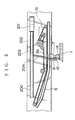
- FIG. 8 is a longitudinal sectional view showing a prior art power feeding unit
- FIGS. 9A, 9 B are side views showing a motor vehicle carrying another prior art power feeding unit
- FIGS. 10A, 10 B are plan views showing the power feeding unit of FIGS. 9A, 9 B.
- FIGS. 11A, 11 B are side views showing a motor vehicle carrying still another prior art power feeding unites.
- FIGS. 12A, 12 B are plan views showing the power feeding unit of FIGS. 11A, 11 B.
- FIGS. 7-5 Before describing an embodiment of the present invention, a motor vehicle to which the present invention is applied is described, referring to FIGS. 7-5.
- FIG. 5 is a perspective view showing an example of a motor vehicle with a sliding door automatic driving unit
- FIG. 6 is a sectional view taken along a line B—B in FIG. 5
- FIG. 7 is a plan view showing the sliding door automatic driving unit.
- the vehicle body 2 has an opening 3 , and an upper rail 4 , a lower guide rail 5 , and a center rail 45 are arranged at a top and bottom sides of the opening 3 and in the center of a rear sidewall of the vehicle body 2 , respectively. And, an upper roller, a lower roller, and a center roller arranged at a front-upper portion B, a front-lower portion C, and a rear-center D of a sliding door 1 , respectively, engage the upper rail 4 , the lower rail 5 , and the center rail 45 slidably.
- a pair of rollers 70 of a lower roller 7 is supported by a pair of vertical axes provided on a roller supporting member 8 , and a running roller 11 is supported by a horizontal axis provided between the vertical axes of the roller supporting member 8 .
- the roller supporting member 8 is attached to a supporting arm 12
- the supporting arm 12 is attached to a L-shaped bracket 14 fixed to the sliding door 1 .
- An automatic driving unit 21 of the sliding door 1 is arranged under a step panel 22 provided under the opening 3 , which automatic driving unit 21 has various parts such as pulleys and equipment such as an electric motor.
- Driven pulleys 23 , 24 are arranged on the respective end portions of the step panel 22 , and idle pulleys 25 , 26 are arranged between the driven pulleys 23 , 24 .
- a driving pulley 27 is arranged between the idle pulley 26 and the driven pulley 23 .
- the driving pulley 27 is made up of a small-diameter toothed pulley 29 and a large-diameter toothed pulley 28 .
- a jointless toothed belt 30 is put round the driven pulleys 23 , 24 , the idle pulleys 25 , 26 , and the toothed pulley 28 .
- the electric motor 31 is fitted to an electromagnetic clutch 32 and fixed to the back of the step panel 22 . And, another jointless toothed belt 34 is put round the small-diameter toothed pulley 29 of the driving pulley 27 and a toothed pulley 33 of the electromagnetic clutch 32 .
- the driving force of the electric motor 31 is transmitted in the following order: the toothed pulley 33 ⁇ the jointless toothed belt 34 ⁇ the toothed pulley 29 (the toothed pulley 28 ) ⁇ the jointless toothed belt 30 .
- the lower guide rail 5 is fixed to the step panel 22 along the belt guide 35 arranged between the driven pulleys 23 , 24 .
- a driving bracket 36 is connected to the jointless toothed belt 30 positioned between the driven pulleys 23 , 24 .
- the jointless toothed belt 30 moves between the driven pulleys 23 , 24 due to a drive of the electric motor 31 .
- the driving bracket 36 is connected to the jointless toothed belt 30 , and the sliding door 1 is driven through the driving bracket 36 .
- the driving bracket 36 is fixed to the roller supporting member 8 of the lower roller 7 .
- FIGS. 1-3 wherein the same parts or members as in the previous figures have the same reference characters.
- FIG. 1 is a perspective view showing the power feeding unit for motor vehicle sliding door in accordance with the present invention
- FIG. 2 is a sectional view taken along a line A—A in FIG. 1
- FIG. 3 is a plan view showing an arrangement of a lower rail and a slide rail of the present invention.
- 200 is a slide rail provided in substantially parallel with the lower rail 5 to guide the sliding door 1 ;
- 201 is a winder to wind up a flexible flat cable (i.e. FFC) 202 ;
- 203 is a feeding wire fixing member being attached to the end of FFC 202 and being guided by the slide rail 200 ;
- 204 and 205 are wiring harnesses; and
- 206 is a connector.
- FFC flexible flat cable
- a rotating drum 201 B having a rotation axis 201 A is provided on the winder 201 and, a fixed drum 201 C is provided between the rotating drum 201 B and the rotation axis 201 A.
- a spring 201 D to rotate the rotation axis 201 A and the rotating drum 201 B in a counterclockwise sense is provided between the drum 201 C and the rotation axis 201 A.
- FFC 202 is inserted through a slit 201 E provided on the rotating drum 201 B.
- FFC 202 is wound to the drum 201 C in a clockwise sense and to the rotating drum 201 B reversely.
- the rotating drum 201 B rotates with withdrawal of FFC 202 , and FFC 202 having wound to the drum 201 C loosens due to rotation of the rotating drum 201 B toward the rotating drum 201 B side.
- a feeding wire fixing member 203 is attached to the end of FFC 202 , and a connection means to connect a conductor of the wiring harness 204 and a conductor of FFC 202 is provided inside the feeding wire fixing member 203 .
- the slide rail 200 has a four-sided cross-section wherein the feeding wire fixing member 203 slides. And, FFC 202 connected with the feeding wire fixing member 203 is arranged inside the slide rail 200 and is protected. The wiring harness 204 connected with the feeding wire fixing member 203 is drawn from a slit of the slide rail 200 .
- a roller 203 A is provided on a side surface of the feeding wire fixing member 203 in order to reduce slide resistance.
- the wiring harness 204 connected with the feeding wire fixing member 203 is secured to the driving bracket 36 with a securing member 207 and is connected a wiring harness 205 on a side of the door 1 through a connector 206 .
- the slide rail 200 substantially parallels the lower rail 5 which makes the sliding door 1 slide. Accordingly, when the sliding door 1 is opened or shut, the wiring harness 204 secured with the securing member 207 shifts, and when the wiring harness 204 shifts, the feeding wire fixing member 203 connected with the wiring harness 204 slides along the slide rail 200 .
- FFC 202 is drawn from the winder 201 or wound up.
- FFC 201 may be connected to the connector 206 directly and the feeding wire fixing member 203 may be provided on the way in order to secure FFC 202 only.
Abstract
A power feeding unit for motor vehicle sliding door, wherein a feeding wire having a large number of circuits on the sliding door side can be connected to another feeding wire on the vehicle body side without breaking the power feeding even during the sliding door is opened or shut, is provided, which includes: a sliding door to be slidably assembled to a vehicle body by means of a supporting arm provided on the sliding door and slidably engaging a guide rail provided on the vehicle body; a slide rail provided on the vehicle body in almost parallel with the guide rail; a feeding wire arranged from the vehicle body to the sliding door for feeding electric power to an electric appliance provided on the sliding door; a winder provided on an end portion of the slide rail for winding the feeding wire; and a feeding wire fixing member fixed to the feeding wire to fix the feeding wire, the feeding wire fixing member sliding along the slide rail along with the supporting arm.
Description
1. Field of the Invention
The present invention generally relates to a power feeding unit for motor vehicle sliding door, and more particularly, a power feeding unit provided between a vehicle body and the sliding door slidably attached to the vehicle body.
2. Description of the Related Art
Conventionally, abutting terminals shown in Japanese Utility Model Application Laid-open No. 4-124555 is known as a power feeding unit for motor vehicle sliding door.
That is, as shown in FIG. 8, in a power feeding unit 100, a first feeding terminal 103 to be connected to a battery side (not illustrated) is provided on a vehicle body 102 side and a second feeding terminal 104 to be connected to a door control unit (not illustrated) side is provided on a sliding door 101 capable of sliding back and forth. A connectable and disconnectable terminal 106 being surrounded with an insulating member 105 is provided on the first feeding terminal 103. And, on shutting the sliding door 101, the terminal 106 is pushed by the end 104 a of the second feeding terminal 104 and is sandwiched, whereby the first and the second feeding terminals 103,104 are connected.
In the above prior art, however, in an opened-state of the sliding door 101, because the power feeding to the sliding door 101 side stops, measures such as prevention of putting a person therebetween cannot be taken. And, because of having double contact points, reliability would not be high.
When the above sliding door is opened, because the sliding door is once pull forward and is slid rearward, it would not be so easy to feed electric power to the sliding door side without a break.
A power feeding unit solving the above problems is, however, disclosed in Japanese Patent Application Laid-open No. 7-222274.
In FIGS. 9A, 9B, 10A, and 10B, a getting-on-and-off opening 112 is formed substantially in a middle portion of a body sidewall portion 111 of a high-roof type motor vehicle 110, and a sliding door 113 slidable back and forth is provided on getting-on-and-off opening 112. At upper and lower portions of the getting-on-and-off opening 112, respective slider rails 114,115 are formed on the body sidewall portion 111. And, another slider rail 116 is formed on the body sidewall portion 111 behind the opening 112.
The other ends of the respective hinge portions 114 c,115 c,116 c are secured to a front-upper portion, a front-lower portion, and a rear-middle portion, respectively, of the sliding door 113. And, the sliding door 113 is slidably supported by the body sidewall portion 111 through the hinge portions 114 c,115 c,116 c, the hinge rollers 114 b,115 b,116 b, and the slider rails 114,115,116.
Over the slider rail 114, a supporting rod 121 is provided. One end portion of the supporting rod 121 is engaged with the body sidewall portion 111 at the front of a getting-on-and-off opening 112. The other end is engaged with an inner panel 111 a inside the body sidewall portion 111 at the back of the getting-on-and-off opening 112.
A cable 123 is wound to the supporting rod 121, and a cave portion 124 a for the cable 123 is formed inside the body sidewall portion 111 in order to prevent the cable 123 from coming into contact with the inner panel 111 a, an outer panel 111 b, and the like. An opening portion 124 b for the cable 123 is formed on the body sidewall portion 111 on a side of the getting-on-and-off opening 112.
The cable 123 is continuously pulled rearward by its own torsional elasticity. And, the cable 123 is connected to an electric appliance 126.
On the other hand, a receiving portion 122 slidable laterally is provided on the hinge portion 114 c, and a ring portion 122 a is formed at the end of the receiving portion 122. A supporting rod 121 is put through the ring portion 122 a and supports the cable 123. And, the other end 123 b of the cable 123 goes through the receiving portion 122 and the hinge portion 114 c and connected to an electric appliance (e.g. speaker) 125 in the sliding door 113.
In the above prior art, however, a large accommodating space of the cable 123, that is, the cave portion 124 a is necessary and further a long cable is necessary, which cause big electric resistance.
And, a larger winding diameter of the cable 123 is required in case that a number of circuits are necessary, which causes a larger receiving space.
Next, another example disclosed in the above Patent Application Laid-open No. 7-222274 will be described hereinafter.
Referring to FIGS. 11A, 11B, 12A, and 12B, a reel mechanism 130 having a coil spring (not illustrated) is provided in the body sidewall portion 111 at the back of the getting-on-and-off opening 112. And, a receiving portion 139 is provided on the hinge portion 114 c of the sliding door 113. The cable 137 wound to the reel mechanism 130 goes through an opening portion 124 b and is secured to the receiving portion 139. And further, the cable 137 goes along the receiving portion 139 and the hinge portion 114 c, and is connected to an electric appliance (e.g. speaker) 125 installed inside the sliding door 113.
The other structures of the sliding door 113 are similar to the above example.
In case of the present power feeding unit, however, the reel with a large diameter is required in order to reduce the winding number of the cable, which makes the unit larger.
Further, a larger reel mechanism is required in case that a number of circuits are necessary or a larger electric wire is used.
In view of the foregoing, an object of the present invention is to provide a power feeding unit for motor vehicle sliding door wherein a feeding wire having a large number of circuits on the sliding door side can be connected to another feeding wire on the vehicle body side without breaking the power feeding even during the sliding door is opened or shut.
In order to achieve the above-described object, as a first aspect of the present invention, a power feeding unit for motor vehicle sliding door in accordance with the present invention includes: a sliding door to be slidably assembled to a vehicle body by means of a supporting arm provided on the sliding door and slidably engaging a guide rail provided on the vehicle body; a slide rail provided on the vehicle body in almost parallel with the guide rail; a feeding wire arranged from the vehicle body to the sliding door for feeding electric power to an electric appliance provided on the sliding door; a winder provided on an end portion of the slide rail for winding the feeding wire; and a feeding wire fixing member fixed to the feeding wire to fix the feeding wire, the feeding wire fixing member sliding along the slide rail along with the supporting arm.
As a second aspect of the present invention, in the structure with the above first aspect, the feeding wire is of a flexible flat cable.
As a third aspect of the present invention, in the structure with either one of the above first and second aspects, the feeding wire drawn from the winder is arranged inside the slide rail.
As a fourth aspect of the present invention, in the structure with either one of the above first and second aspects, a wiring harness is connected to the electric appliance, and a connecting means to connect the wiring harness with the feeding wire being drawn from the winder is provided on the feeding wire fixing member.
As a fifth aspect of the present invention, in the structure with either one of the above first and second aspects, the feeding wire is connected by means of an electric connector at the supporting arm.
As a sixth aspect of the present invention, in the structure with any one of the proceeding aspects, the feeding wire is secured with a securing member at the supporting arm.
According to the above-described structure of the present invention, the following advantages are provided.
(1) The feeding wire having a plurality of circuits can be provided between the sliding doors and the vehicle body, wherein the power feeding can remain alive even during the sliding door is opened or shut.
(2) The feeding wire having a large number of circuits can be dealt with.
(3) Damage of the feeding wire is prevented by the slide rail.
(4) Connection between with the feeding wire and the wiring harness can be carried out easily.
(5) The power feeding unit can be mounted to the vehicle body easily.
(6) Tensile force by the winder works on the securing member, whereby damage of the feeding wire due to opening and shutting of the sliding door can be prevented.
The above and other objects and features of the present invention will become more apparent from the following description taken in conjunction with the accompanying drawings.
FIG. 1 is a perspective view showing the power feeding unit for motor vehicle sliding door in accordance with the present invention;
FIG. 2 is a sectional view taken along a line A—A in FIG. 1;
FIG. 3 is a plan view showing an arrangement of a lower rail and a slide rail of the present invention;
FIGS. 4A, 4B are sectional views of a winder;
FIG. 5 is a perspective view showing an example of a motor vehicle with a sliding door automatic driving unit;
FIG. 6 is a sectional view taken along a line B—B in FIG. 5;
FIG. 7 is a plan view showing the sliding door automatic driving unit;
FIG. 8 is a longitudinal sectional view showing a prior art power feeding unit;
FIGS. 9A, 9B are side views showing a motor vehicle carrying another prior art power feeding unit;
FIGS. 10A, 10B are plan views showing the power feeding unit of FIGS. 9A, 9B.
FIGS. 11A, 11B are side views showing a motor vehicle carrying still another prior art power feeding unites; and
FIGS. 12A, 12B are plan views showing the power feeding unit of FIGS. 11A, 11B.
An embodiment of the present invention will now be described in further detail with reference to the accompanying drawings.
However, before describing an embodiment of the present invention, a motor vehicle to which the present invention is applied is described, referring to FIGS. 7-5.
FIG. 5 is a perspective view showing an example of a motor vehicle with a sliding door automatic driving unit; FIG. 6 is a sectional view taken along a line B—B in FIG. 5; and FIG. 7 is a plan view showing the sliding door automatic driving unit.
The vehicle body 2 has an opening 3, and an upper rail 4, a lower guide rail 5, and a center rail 45 are arranged at a top and bottom sides of the opening 3 and in the center of a rear sidewall of the vehicle body 2, respectively. And, an upper roller, a lower roller, and a center roller arranged at a front-upper portion B, a front-lower portion C, and a rear-center D of a sliding door 1, respectively, engage the upper rail 4, the lower rail 5, and the center rail 45 slidably.
A pair of rollers 70 of a lower roller 7 is supported by a pair of vertical axes provided on a roller supporting member 8, and a running roller 11 is supported by a horizontal axis provided between the vertical axes of the roller supporting member 8. The roller supporting member 8 is attached to a supporting arm 12, and the supporting arm 12 is attached to a L-shaped bracket 14 fixed to the sliding door 1.
An automatic driving unit 21 of the sliding door 1 is arranged under a step panel 22 provided under the opening 3, which automatic driving unit 21 has various parts such as pulleys and equipment such as an electric motor. Driven pulleys 23,24 are arranged on the respective end portions of the step panel 22, and idle pulleys 25,26 are arranged between the driven pulleys 23,24. A driving pulley 27 is arranged between the idle pulley 26 and the driven pulley 23. The driving pulley 27 is made up of a small-diameter toothed pulley 29 and a large-diameter toothed pulley 28. A jointless toothed belt 30 is put round the driven pulleys 23,24, the idle pulleys 25,26, and the toothed pulley 28.
The electric motor 31 is fitted to an electromagnetic clutch 32 and fixed to the back of the step panel 22. And, another jointless toothed belt 34 is put round the small-diameter toothed pulley 29 of the driving pulley 27 and a toothed pulley 33 of the electromagnetic clutch 32. Through the electromagnetic clutch 32, the driving force of the electric motor 31 is transmitted in the following order: the toothed pulley 33→the jointless toothed belt 34→the toothed pulley 29 (the toothed pulley 28)→the jointless toothed belt 30.
And, the lower guide rail 5 is fixed to the step panel 22 along the belt guide 35 arranged between the driven pulleys 23,24. And, a driving bracket 36 is connected to the jointless toothed belt 30 positioned between the driven pulleys 23,24.
According to the sliding door automatic driving unit 21 of the above structure, the jointless toothed belt 30 moves between the driven pulleys 23,24 due to a drive of the electric motor 31. The driving bracket 36 is connected to the jointless toothed belt 30, and the sliding door 1 is driven through the driving bracket 36. The driving bracket 36 is fixed to the roller supporting member 8 of the lower roller 7.
Hereinafter, an embodiment of the present invention will be described referring to FIGS. 1-3, wherein the same parts or members as in the previous figures have the same reference characters.
FIG. 1 is a perspective view showing the power feeding unit for motor vehicle sliding door in accordance with the present invention; FIG. 2 is a sectional view taken along a line A—A in FIG. 1; and FIG. 3 is a plan view showing an arrangement of a lower rail and a slide rail of the present invention.
In FIGS. 1-3, 200 is a slide rail provided in substantially parallel with the lower rail 5 to guide the sliding door 1; 201 is a winder to wind up a flexible flat cable (i.e. FFC) 202; 203 is a feeding wire fixing member being attached to the end of FFC 202 and being guided by the slide rail 200; 204 and 205 are wiring harnesses; and 206 is a connector.
As shown in FIGS. 4A, 4B, a rotating drum 201B having a rotation axis 201A is provided on the winder 201 and, a fixed drum 201C is provided between the rotating drum 201B and the rotation axis 201A. A spring 201D to rotate the rotation axis 201A and the rotating drum 201B in a counterclockwise sense is provided between the drum 201C and the rotation axis 201A.
As shown in FIG. 4A, FFC 202 is inserted through a slit 201E provided on the rotating drum 201B. FFC 202 is wound to the drum 201C in a clockwise sense and to the rotating drum 201B reversely.
On the other hand, as shown in FIG. 4B, the rotating drum 201B rotates with withdrawal of FFC 202, and FFC 202 having wound to the drum 201C loosens due to rotation of the rotating drum 201B toward the rotating drum 201B side.
A feeding wire fixing member 203 is attached to the end of FFC 202, and a connection means to connect a conductor of the wiring harness 204 and a conductor of FFC 202 is provided inside the feeding wire fixing member 203.
As shown in FIG. 2, the slide rail 200 has a four-sided cross-section wherein the feeding wire fixing member 203 slides. And, FFC 202 connected with the feeding wire fixing member 203 is arranged inside the slide rail 200 and is protected. The wiring harness 204 connected with the feeding wire fixing member 203 is drawn from a slit of the slide rail 200.
And, a roller 203A is provided on a side surface of the feeding wire fixing member 203 in order to reduce slide resistance. The wiring harness 204 connected with the feeding wire fixing member 203 is secured to the driving bracket 36 with a securing member 207 and is connected a wiring harness 205 on a side of the door 1 through a connector 206.
As shown in FIG. 3, the slide rail 200 substantially parallels the lower rail 5 which makes the sliding door 1 slide. Accordingly, when the sliding door 1 is opened or shut, the wiring harness 204 secured with the securing member 207 shifts, and when the wiring harness 204 shifts, the feeding wire fixing member 203 connected with the wiring harness 204 slides along the slide rail 200.
When the feeding wire fixing member 203 shifts along the slide rail 200, FFC 202 is drawn from the winder 201 or wound up.
In the above embodiment, though the wiring harness 204 is connected to FFC 202 at the feeding wire fixing member 203, FFC 201 may be connected to the connector 206 directly and the feeding wire fixing member 203 may be provided on the way in order to secure FFC 202 only.
The present invention can be variously changed and modified by those skilled in the art within the scope of the present invention, which should be construed as being included therein.
Claims (16)
1. A power feeding unit for a motor vehicle sliding door which is slidably assembled to a vehicle body by means of a supporting arm, provided on the sliding door, which slidably engages a guide rail provided on the vehicle body, said power feeding unit comprising
a continuous slide rail provided on the vehicle body in almost parallel with the guide rail;
a feeding wire arranged from the vehicle body to the sliding door and arranged to feed electric power to an electric appliance provided on the sliding door;
a winder provided on an end portion of the continuous slide rail and arranged to wind the feeding wire; and
a feeding wire fixing member fixed to the feeding wire to fix the feeding wire, the feeding wire fixing member being arranged to engage and slide along the continuous slide rail along with the supporting arm.
2. The power feeding unit according to claim 1, wherein
the feeding wire is of a flexible flat cable.
3. The power feeding unit according to claim 2, wherein
the feeding wire drawn from the winder is arranged inside the slide rail.
4. The power feeding unit according to claim 3, wherein
the feeding wire is secured with a securing member at the supporting arm.
5. The power feeding unit according to claim 2, wherein
a wiring harness is connected to the electric appliance, and a connecting means to connect the wiring harness with the feeding wire being drawn from the winder is provided on the feeding wire fixing member.
6. The power feeding unit according to claim 5, wherein the feeding wire is secured with a securing member at the supporting arm.
7. The power feeding unit according to claim 2, wherein
the feeding wire is connected by means of an electric connector at the supporting arm.
8. The power feeding unit according to claim 7, wherein
the feeding wire is secured with a securing member at the supporting arm.
9. The power feeding unit according to claim 2, wherein
the feeding wire is secured with a securing member at the supporting arm.
10. The power feeding unit according to claim 1, wherein
the feeding wire drawn from the winder is arranged inside the slide rail.
11. The power feeding unit according to claim 10, wherein
the feeding wire is secured with a securing member at the supporting arm.
12. The power feeding unit according to claim 1, wherein
a wiring harness is connected to the electric appliance, and a connecting means to connect the wiring harness with the feeding wire being drawn from the winder is provided on the feeding wire fixing member.
13. The power feeding unit according to claim 12, wherein
the feeding wire is secured with a securing member at the supporting arm.
14. The power feeding unit according to claim 1, wherein
the feeding wire is connected by means of an electric connector at the supporting arm.
15. The power feeding unit according to claim 14, wherein
the feeding wire is secured with a securing member at the supporting arm.
16. The power feeding unit according to claim 1, wherein
the feeding wire is secured with a securing member at the supporting arm.
Applications Claiming Priority (2)
| Application Number | Priority Date | Filing Date | Title |
|---|---|---|---|
| JP11-109017 | 1999-04-16 | ||
| JP11109017A JP2000297579A (en) | 1999-04-16 | 1999-04-16 | Power feeding system for sliding door in automobile |
Publications (1)
| Publication Number | Publication Date |
|---|---|
| US6321489B1 true US6321489B1 (en) | 2001-11-27 |
Family
ID=14499480
Family Applications (1)
| Application Number | Title | Priority Date | Filing Date |
|---|---|---|---|
| US09/537,428 Expired - Fee Related US6321489B1 (en) | 1999-04-16 | 2000-03-27 | Power feeding unit for motor vehicle sliding door |
Country Status (3)
| Country | Link |
|---|---|
| US (1) | US6321489B1 (en) |
| JP (1) | JP2000297579A (en) |
| DE (1) | DE10018332B4 (en) |
Cited By (28)
| Publication number | Priority date | Publication date | Assignee | Title |
|---|---|---|---|---|
| US6517365B1 (en) * | 2000-05-11 | 2003-02-11 | Delphi Technologies, Inc. | Wiring assembly for supplying power to a sliding door |
| US6539669B1 (en) * | 2000-09-14 | 2003-04-01 | Westinghouse Air Brake Technologies Corporation | Plug door drive system |
| US20030121692A1 (en) * | 2001-12-11 | 2003-07-03 | Mitsunobu Kato | Device for absorbing harness slack |
| US6603076B2 (en) * | 2000-04-11 | 2003-08-05 | Yazaki Corporation | Power supply structure in sliding structure |
| US20030164625A1 (en) * | 2002-02-20 | 2003-09-04 | Simon Dobson | Flexible wiring harness for a vehicle partition assembly |
| US20030184118A1 (en) * | 2002-03-29 | 2003-10-02 | Yazaki Corporation | Electric wire excess length absorbing device and sliding door-use power feeding apparatus using the same |
| WO2003091050A1 (en) * | 2002-04-26 | 2003-11-06 | Oy Mosera Ltd. | Arrangement in a sliding door of a vehicle |
| US20030221370A1 (en) * | 2002-05-15 | 2003-12-04 | Otis Elevator Company | Door closing device |
| US6781058B1 (en) | 2003-02-20 | 2004-08-24 | Stoneridge Inc., Alphabet Division | Cable guide assembly for a vehicle sliding door |
| US20050110300A1 (en) * | 2003-11-20 | 2005-05-26 | Intier Automotive | Drive mechanism for selectively opening and closing a closure panel manually or automatically |
| US20050264033A1 (en) * | 2004-05-31 | 2005-12-01 | The Furukawa Electric Co., Ltd. | Power supply device for a sliding door |
| US20060042168A1 (en) * | 2004-08-26 | 2006-03-02 | Aisin Seiki Kabushiki Kaisha | Vehicle door opening and closing device |
| US20060284447A1 (en) * | 2005-06-17 | 2006-12-21 | Mitsuba Corporation | Sliding door opening and closing device |
| US20070108798A1 (en) * | 2005-11-11 | 2007-05-17 | Aisin Seiki Kabushiki Kaisha | Slide door opening and closing apparatus for vehicle |
| US20070125001A1 (en) * | 2005-12-07 | 2007-06-07 | Choi Jae H | Moving wiring system for vehicle |
| US20070158108A1 (en) * | 2006-01-10 | 2007-07-12 | Yazaki Corporation | Power-supplying apparatus for sliding structure |
| US20090008991A1 (en) * | 2006-07-31 | 2009-01-08 | The Furukawa Electric Co, Ltd. | Power supply apparatus for sliding door |
| US20100193216A1 (en) * | 2007-07-27 | 2010-08-05 | Furukawa Electric Co., Ltd. | Power supply apparatus for sliding door |
| US20120261894A1 (en) * | 2009-11-20 | 2012-10-18 | Toshihiko Ishida | Step unit |
| US20160201375A1 (en) * | 2014-08-06 | 2016-07-14 | Mitsui Kinzoku Act Corporation | Door opening and closing apparatus |
| US20160245006A1 (en) * | 2015-02-24 | 2016-08-25 | Airbus Helicopters Deutschland GmbH | Sliding closing element, in particular a sliding door or a sliding window, for a sliding closing element arrangement of a vehicle, in particular of an aircraft |
| US20160244004A1 (en) * | 2013-10-11 | 2016-08-25 | Yazaki Corporation | Power-supplying device and assembly method of power-supplying device |
| US9828796B2 (en) | 2014-08-06 | 2017-11-28 | Mitsui Kinzoku Act Corporation | Door opening and closing apparatus |
| US9834970B2 (en) | 2014-08-06 | 2017-12-05 | Mitsui Kinzoku Act Corporation | Door opening and closing apparatus |
| US20190119966A1 (en) * | 2017-10-20 | 2019-04-25 | Airbus Helicopters | Vehicle provided with a sliding door |
| EP3805502A1 (en) * | 2019-10-10 | 2021-04-14 | Renault S.A.S. | Centring device for a sliding door |
| US20210277700A1 (en) * | 2020-03-06 | 2021-09-09 | Aisin Seiki Kabushiki Kaisha | Opening and closing body drive device for vehicle |
| US11447994B2 (en) * | 2016-11-11 | 2022-09-20 | Gebr. Bode Gmbh & Co. Kg | Drive device for an element to be driven |
Families Citing this family (13)
| Publication number | Priority date | Publication date | Assignee | Title |
|---|---|---|---|---|
| FR2817803B1 (en) * | 2000-12-13 | 2003-03-14 | France Design | RETRACTABLE ROOF FOR VEHICLE COMPRISING ROOF ELEMENTS EQUIPPED WITH TELESCOPIC SLIDES |
| JP2003048495A (en) * | 2001-08-07 | 2003-02-18 | Yazaki Corp | Electric power feeder for slide door |
| ITTO20011100A1 (en) * | 2001-11-23 | 2003-05-23 | Framatome Connectors Italia | CONNECTION GROUP FOR THE CONNECTION OF AN ELECTRIC SYSTEM OF A VEHICLE TO ELECTRICAL COMPONENTS OF A SLIDING DOOR OF THE |
| DE10334137B4 (en) * | 2003-07-23 | 2012-11-15 | Volkswagen Ag | Power supply to a sliding door of a motor vehicle |
| JP4682726B2 (en) * | 2005-07-12 | 2011-05-11 | アイシン精機株式会社 | Vehicle step device |
| JP5101853B2 (en) * | 2005-12-27 | 2012-12-19 | 矢崎総業株式会社 | Link-type movable harness wiring structure |
| JP2008030716A (en) * | 2006-07-31 | 2008-02-14 | Furukawa Electric Co Ltd:The | Power feeding device for slide door |
| JP2008030715A (en) * | 2006-07-31 | 2008-02-14 | Furukawa Electric Co Ltd:The | Power feeding device for slide door |
| JP2009179117A (en) * | 2008-01-29 | 2009-08-13 | Autonetworks Technologies Ltd | Wire harness for automobile |
| JP5233722B2 (en) * | 2009-02-12 | 2013-07-10 | 日産自動車株式会社 | Routing structure for sliding door harness |
| DE102014200934A1 (en) * | 2014-01-20 | 2015-07-23 | Leoni Bordnetz-Systeme Gmbh | Energy supply clutch |
| JP6749143B2 (en) * | 2015-07-29 | 2020-09-02 | 矢崎総業株式会社 | Power supply structure for movable body |
| JP2021139190A (en) * | 2020-03-06 | 2021-09-16 | 株式会社アイシン | Vehicle opening/closing body drive unit |
Citations (8)
| Publication number | Priority date | Publication date | Assignee | Title |
|---|---|---|---|---|
| JPH04124555A (en) | 1990-09-14 | 1992-04-24 | Toshiba Corp | Refrigerator |
| JPH07222274A (en) | 1994-01-31 | 1995-08-18 | Fujitsu Ten Ltd | Wiring structure for on-vehicle speaker |
| US5453585A (en) * | 1994-07-20 | 1995-09-26 | Golden West Communications, Inc. | Cable retraction system |
| US5536061A (en) * | 1994-12-05 | 1996-07-16 | Chrysler Corporation | Automotive vehicle body with powered sliding side door |
| US5581944A (en) * | 1993-07-08 | 1996-12-10 | The Stanley Works | Electrical link and sensor system for automatic sliding doors |
| US5657940A (en) * | 1995-01-12 | 1997-08-19 | Yazaki Corporation | Relay device for rotating members |
| US6076883A (en) * | 1997-04-25 | 2000-06-20 | Kiekert Ag | Electrical-cable system for motor-vehicle sliding door |
| US6108976A (en) * | 1997-04-02 | 2000-08-29 | Amso., Co, Ltd. | Feeder arrangement of sliding door |
Family Cites Families (1)
| Publication number | Priority date | Publication date | Assignee | Title |
|---|---|---|---|---|
| JP2543239Y2 (en) * | 1991-04-30 | 1997-08-06 | 株式会社大井製作所 | Power supply device for automotive sliding door |
-
1999
- 1999-04-16 JP JP11109017A patent/JP2000297579A/en not_active Abandoned
-
2000
- 2000-03-27 US US09/537,428 patent/US6321489B1/en not_active Expired - Fee Related
- 2000-04-13 DE DE10018332A patent/DE10018332B4/en not_active Expired - Fee Related
Patent Citations (8)
| Publication number | Priority date | Publication date | Assignee | Title |
|---|---|---|---|---|
| JPH04124555A (en) | 1990-09-14 | 1992-04-24 | Toshiba Corp | Refrigerator |
| US5581944A (en) * | 1993-07-08 | 1996-12-10 | The Stanley Works | Electrical link and sensor system for automatic sliding doors |
| JPH07222274A (en) | 1994-01-31 | 1995-08-18 | Fujitsu Ten Ltd | Wiring structure for on-vehicle speaker |
| US5453585A (en) * | 1994-07-20 | 1995-09-26 | Golden West Communications, Inc. | Cable retraction system |
| US5536061A (en) * | 1994-12-05 | 1996-07-16 | Chrysler Corporation | Automotive vehicle body with powered sliding side door |
| US5657940A (en) * | 1995-01-12 | 1997-08-19 | Yazaki Corporation | Relay device for rotating members |
| US6108976A (en) * | 1997-04-02 | 2000-08-29 | Amso., Co, Ltd. | Feeder arrangement of sliding door |
| US6076883A (en) * | 1997-04-25 | 2000-06-20 | Kiekert Ag | Electrical-cable system for motor-vehicle sliding door |
Cited By (50)
| Publication number | Priority date | Publication date | Assignee | Title |
|---|---|---|---|---|
| US6603076B2 (en) * | 2000-04-11 | 2003-08-05 | Yazaki Corporation | Power supply structure in sliding structure |
| US6517365B1 (en) * | 2000-05-11 | 2003-02-11 | Delphi Technologies, Inc. | Wiring assembly for supplying power to a sliding door |
| US6539669B1 (en) * | 2000-09-14 | 2003-04-01 | Westinghouse Air Brake Technologies Corporation | Plug door drive system |
| US6818827B2 (en) * | 2001-12-11 | 2004-11-16 | Yazaki Corporation | Device for absorbing harness slack |
| US20030121692A1 (en) * | 2001-12-11 | 2003-07-03 | Mitsunobu Kato | Device for absorbing harness slack |
| US20030164625A1 (en) * | 2002-02-20 | 2003-09-04 | Simon Dobson | Flexible wiring harness for a vehicle partition assembly |
| EP1342876A1 (en) * | 2002-02-20 | 2003-09-10 | ArvinMeritor Light Vehicle Systems-France | Vehicle with movable partition |
| US6793259B2 (en) * | 2002-03-29 | 2004-09-21 | Yazaki Corporation | Electric wire excess length absorbing device and sliding door-use power feeding apparatus using the same |
| US20030184118A1 (en) * | 2002-03-29 | 2003-10-02 | Yazaki Corporation | Electric wire excess length absorbing device and sliding door-use power feeding apparatus using the same |
| WO2003091050A1 (en) * | 2002-04-26 | 2003-11-06 | Oy Mosera Ltd. | Arrangement in a sliding door of a vehicle |
| US6918211B2 (en) * | 2002-05-15 | 2005-07-19 | Otis Elevator Company | Door closing device |
| US20030221370A1 (en) * | 2002-05-15 | 2003-12-04 | Otis Elevator Company | Door closing device |
| US6781058B1 (en) | 2003-02-20 | 2004-08-24 | Stoneridge Inc., Alphabet Division | Cable guide assembly for a vehicle sliding door |
| US7144068B2 (en) | 2003-11-20 | 2006-12-05 | Intier Automotive Closures Inc. | Drive mechanism for selectively opening and closing a closure panel manually or automatically |
| US20050110300A1 (en) * | 2003-11-20 | 2005-05-26 | Intier Automotive | Drive mechanism for selectively opening and closing a closure panel manually or automatically |
| US20050264033A1 (en) * | 2004-05-31 | 2005-12-01 | The Furukawa Electric Co., Ltd. | Power supply device for a sliding door |
| US7086687B2 (en) * | 2004-05-31 | 2006-08-08 | The Furukawa Electric Co., Ltd. | Power supply device for a sliding door |
| US20060042168A1 (en) * | 2004-08-26 | 2006-03-02 | Aisin Seiki Kabushiki Kaisha | Vehicle door opening and closing device |
| US7287805B2 (en) * | 2004-08-26 | 2007-10-30 | Aisin Seiki Kabushiki Kaisha | Vehicle door opening and closing device |
| US20060284447A1 (en) * | 2005-06-17 | 2006-12-21 | Mitsuba Corporation | Sliding door opening and closing device |
| US7328934B2 (en) * | 2005-06-17 | 2008-02-12 | Mitsuba Corporation | Sliding door opening and closing device |
| US20070108798A1 (en) * | 2005-11-11 | 2007-05-17 | Aisin Seiki Kabushiki Kaisha | Slide door opening and closing apparatus for vehicle |
| US7585014B2 (en) * | 2005-11-11 | 2009-09-08 | Aisin Seiki Kabushiki Kaisha | Slide door opening and closing apparatus for vehicle |
| US7464500B2 (en) * | 2005-12-07 | 2008-12-16 | Kia Motors Company | Moving wiring system for vehicle |
| US20070125001A1 (en) * | 2005-12-07 | 2007-06-07 | Choi Jae H | Moving wiring system for vehicle |
| US20070158108A1 (en) * | 2006-01-10 | 2007-07-12 | Yazaki Corporation | Power-supplying apparatus for sliding structure |
| US7375281B2 (en) * | 2006-01-10 | 2008-05-20 | Yazaki Corporation | Power-supplying apparatus for sliding structure |
| US8508068B2 (en) * | 2006-07-31 | 2013-08-13 | The Furukawa Electric Co., Ltd. | Power supply apparatus for sliding door |
| US20090008991A1 (en) * | 2006-07-31 | 2009-01-08 | The Furukawa Electric Co, Ltd. | Power supply apparatus for sliding door |
| US20120146407A1 (en) * | 2006-07-31 | 2012-06-14 | The Furukawa Electric Co, Ltd. | Power supply apparatus for sliding door |
| US8212383B2 (en) * | 2006-07-31 | 2012-07-03 | The Furukawa Electric Co., Ltd. | Power supply apparatus for sliding door |
| US20100193216A1 (en) * | 2007-07-27 | 2010-08-05 | Furukawa Electric Co., Ltd. | Power supply apparatus for sliding door |
| US8247921B2 (en) * | 2007-07-27 | 2012-08-21 | Furukawa Electric Co., Ltd. | Power supply apparatus for sliding door |
| US20120261894A1 (en) * | 2009-11-20 | 2012-10-18 | Toshihiko Ishida | Step unit |
| US8622408B2 (en) * | 2009-11-20 | 2014-01-07 | Aisin Seiki Kabushiki Kaisha | Step unit |
| US11046260B2 (en) * | 2013-10-11 | 2021-06-29 | Yazaki Corporation | Power-supplying device and assembly method of power-supplying device |
| US20160244004A1 (en) * | 2013-10-11 | 2016-08-25 | Yazaki Corporation | Power-supplying device and assembly method of power-supplying device |
| US20160201375A1 (en) * | 2014-08-06 | 2016-07-14 | Mitsui Kinzoku Act Corporation | Door opening and closing apparatus |
| US9803407B2 (en) * | 2014-08-06 | 2017-10-31 | Mitsui Kinzoku Act Corporation | Door opening and closing apparatus |
| US9828796B2 (en) | 2014-08-06 | 2017-11-28 | Mitsui Kinzoku Act Corporation | Door opening and closing apparatus |
| US9834970B2 (en) | 2014-08-06 | 2017-12-05 | Mitsui Kinzoku Act Corporation | Door opening and closing apparatus |
| US20160245006A1 (en) * | 2015-02-24 | 2016-08-25 | Airbus Helicopters Deutschland GmbH | Sliding closing element, in particular a sliding door or a sliding window, for a sliding closing element arrangement of a vehicle, in particular of an aircraft |
| US10066430B2 (en) * | 2015-02-24 | 2018-09-04 | Airbus Helicopters Deutschland GmbH | Sliding closing element, in particular a sliding door or a sliding window, for a sliding closing element arrangement of a vehicle, in particular of an aircraft |
| US11447994B2 (en) * | 2016-11-11 | 2022-09-20 | Gebr. Bode Gmbh & Co. Kg | Drive device for an element to be driven |
| US20190119966A1 (en) * | 2017-10-20 | 2019-04-25 | Airbus Helicopters | Vehicle provided with a sliding door |
| US10947767B2 (en) * | 2017-10-20 | 2021-03-16 | Airbus Helicopterrs | Vehicle provided with a sliding door |
| EP3805502A1 (en) * | 2019-10-10 | 2021-04-14 | Renault S.A.S. | Centring device for a sliding door |
| FR3101909A1 (en) * | 2019-10-10 | 2021-04-16 | Renault S.A.S | Centering device for a sliding door. |
| US20210277700A1 (en) * | 2020-03-06 | 2021-09-09 | Aisin Seiki Kabushiki Kaisha | Opening and closing body drive device for vehicle |
| US11598140B2 (en) * | 2020-03-06 | 2023-03-07 | Aisin Corporation | Opening and closing body drive device for vehicle |
Also Published As
| Publication number | Publication date |
|---|---|
| DE10018332A1 (en) | 2000-10-26 |
| JP2000297579A (en) | 2000-10-24 |
| DE10018332B4 (en) | 2004-07-08 |
Similar Documents
| Publication | Publication Date | Title |
|---|---|---|
| US6321489B1 (en) | Power feeding unit for motor vehicle sliding door | |
| US6492592B1 (en) | Electricity supplying structure on motor vehicle sliding door | |
| CN108266954B (en) | Built-in refrigerator including wire cover unit | |
| EP2100777B1 (en) | Power supply device for slide door | |
| US5531046A (en) | Power sliding window assembly | |
| US8816525B2 (en) | Electric power supply device for sliding door | |
| US7328934B2 (en) | Sliding door opening and closing device | |
| US20020014348A1 (en) | Structure of installing wire harness for sliding door | |
| US7287805B2 (en) | Vehicle door opening and closing device | |
| EP2947249B1 (en) | Device for opening and closing vehicle door | |
| US6793259B2 (en) | Electric wire excess length absorbing device and sliding door-use power feeding apparatus using the same | |
| US7057109B2 (en) | Guide protector for harness, wire-excessive portion absorbing structure therewith, and fixing method of guide protector for harness | |
| JP2016165993A (en) | Wiring structure of wire harness | |
| JP2001128350A (en) | Flat cable winder | |
| JPH11122791A (en) | Open/close member structure | |
| JPS5820887A (en) | Tape drive apparatus for garage door opening and closing apparatus | |
| JP3692700B2 (en) | Power supply structure for sliding door | |
| CN217233204U (en) | Sliding door opening/closing device for vehicle | |
| JPH0714608Y2 (en) | Power supply device for self-propelled switchgear | |
| JP4804988B2 (en) | Mounting method of power supply device for sliding door | |
| WO2022118909A1 (en) | Driving device | |
| JPH11192903A (en) | Power supply for automobile slide door | |
| JPH11166359A (en) | Feeding structure for sliding door | |
| WO2022092174A1 (en) | Carrier plate and object movement device | |
| JP4704908B2 (en) | Link door harness wiring structure |
Legal Events
| Date | Code | Title | Description |
|---|---|---|---|
| AS | Assignment |
Owner name: YAZAKI CORPORATION, JAPAN Free format text: ASSIGNMENT OF ASSIGNORS INTEREST;ASSIGNORS:MUROFUSHI, SATORU;NISHIJIMA, MASATAKA;REEL/FRAME:010651/0658 Effective date: 20000315 |
|
| FEPP | Fee payment procedure |
Free format text: PAYOR NUMBER ASSIGNED (ORIGINAL EVENT CODE: ASPN); ENTITY STATUS OF PATENT OWNER: LARGE ENTITY |
|
| FPAY | Fee payment |
Year of fee payment: 4 |
|
| REMI | Maintenance fee reminder mailed | ||
| LAPS | Lapse for failure to pay maintenance fees | ||
| STCH | Information on status: patent discontinuation |
Free format text: PATENT EXPIRED DUE TO NONPAYMENT OF MAINTENANCE FEES UNDER 37 CFR 1.362 |
|
| FP | Lapsed due to failure to pay maintenance fee |
Effective date: 20091127 |