US6311565B1 - Techniques and equipment for assessing the structural integrity of subterranean tower anchor rods - Google Patents
Techniques and equipment for assessing the structural integrity of subterranean tower anchor rods Download PDFInfo
- Publication number
- US6311565B1 US6311565B1 US09/228,336 US22833699A US6311565B1 US 6311565 B1 US6311565 B1 US 6311565B1 US 22833699 A US22833699 A US 22833699A US 6311565 B1 US6311565 B1 US 6311565B1
- Authority
- US
- United States
- Prior art keywords
- rod
- anchor
- ultrasonic energy
- assessing
- returned
- Prior art date
- Legal status (The legal status is an assumption and is not a legal conclusion. Google has not performed a legal analysis and makes no representation as to the accuracy of the status listed.)
- Expired - Lifetime
Links
Images


Classifications
-
- G—PHYSICS
- G01—MEASURING; TESTING
- G01N—INVESTIGATING OR ANALYSING MATERIALS BY DETERMINING THEIR CHEMICAL OR PHYSICAL PROPERTIES
- G01N29/00—Investigating or analysing materials by the use of ultrasonic, sonic or infrasonic waves; Visualisation of the interior of objects by transmitting ultrasonic or sonic waves through the object
- G01N29/22—Details, e.g. general constructional or apparatus details
- G01N29/223—Supports, positioning or alignment in fixed situation
-
- G—PHYSICS
- G01—MEASURING; TESTING
- G01N—INVESTIGATING OR ANALYSING MATERIALS BY DETERMINING THEIR CHEMICAL OR PHYSICAL PROPERTIES
- G01N29/00—Investigating or analysing materials by the use of ultrasonic, sonic or infrasonic waves; Visualisation of the interior of objects by transmitting ultrasonic or sonic waves through the object
- G01N29/22—Details, e.g. general constructional or apparatus details
- G01N29/28—Details, e.g. general constructional or apparatus details providing acoustic coupling, e.g. water
-
- G—PHYSICS
- G01—MEASURING; TESTING
- G01N—INVESTIGATING OR ANALYSING MATERIALS BY DETERMINING THEIR CHEMICAL OR PHYSICAL PROPERTIES
- G01N2291/00—Indexing codes associated with group G01N29/00
- G01N2291/26—Scanned objects
- G01N2291/269—Various geometry objects
Definitions
- This invention relates to techniques and equipment for assessing integrity of anchor rods such as those used to support transmission towers and more particularly to methods and associated apparatus for making these assessments without damaging the load-bearing capability of the rods or excavating the terrain in which they may be implanted.
- the boom in cellular telephone usage and other forms of wireless communication has dramatically increased the number of transmission towers employed today. These towers frequently are guyed, with multiple elongated wire braces spaced about the base of a tower supporting and assisting in counteracting the effects of upper-level winds on the position and integrity of the tower.
- wire braces may terminate in a device such as an equalizer plate, to which a steel rod, typically (although not necessarily) ten to fourteen feet long, is connected at one end. In such situations the other end of the rod may be embedded in concrete and implanted in the ground, thus serving to anchor its associated wire braces and thereby moor the tower.
- anchor rods may, of course, have flaws existing as a consequence of their formation.
- the acts of connecting an end to an equalizer plate, embedding the opposite end in concrete, and burying a rod partially underground may also create cracks or other flaws in the rod.
- the anchor rods—even if initially without flaws—further may corrode over time. Wind-related vibrations of the rods additionally cause wallows, or depressions circumscribing their circumferences, in the ground beginning at their entry points therein, so that potentially-harmful surface water may traverse the entire subterranean lengths of the rods.
- the present invention fulfills this need, providing methods useful for in-field (or remote) analysis of rod integrity without excavation of soil. Practicing the methods of the invention additionally is unlikely to damage the rods or the concrete in which they may be embedded. In some circumstances a small amount of metal might need to be removed from the cosmetic weld joining the rod to an equalizer plate (or similar device); this act does not degrade performance of the rod or plate to any measurable extent, however.
- Techniques encompassed by the present invention include transmitting ultrasonic (or other suitable) energy from the above-ground end of a rod to its buried end and receiving the energy returned therefrom.
- Such returned energy if ultrasonic, manifests in both direct and mode-converted states, either or both may be analyzed to assist in detecting flaws, corrosion, wastage, or other degradation of the rod.
- Data from a field evaluation may be compared with baseline data maintained either for a specific rod or for rods of similar composition and length (or both), and periodic field evaluations of a rod may be used to analyze trends in its structure over time.
- FIG. 1 An example of such a plate 10 is shown in FIG. 1 . Contrary to the design of many other connectors, the equalizer plate 10 of FIG. 1 contains a recess into which the head end of rod 14 is fitted. The head end thereafter is welded to plate 10 , rendering it inaccessible from the exterior of the plate 10 .
- the invention thus also contemplates preparing the surface of the equalizer plate and head end of a rod, if necessary, to improve the quality of the acoustic signal transmitted through the rod.
- preparation may include removing a portion of the weld or otherwise creating a small flat surface at or adjacent the head end of the rod and perpendicular (or substantially so) to the longitudinal axis of the rod.
- a portable transducer may then be acoustically coupled to the prepared surface and used to transmit ultrasonic energy through the length of the rod and receive any returned energy for analysis.
- the prepared surface may in some cases be coated with a cold-galvanize compound (such as, but not necessarily, a sprayable material containing zinc) to protect the prepared surface against rust. Thereafter, the prepared surface need merely be dusted to remove dirt or debris thereon before conducting further tests.
- a cold-galvanize compound such as, but not necessarily, a sprayable material containing zinc
- anchor rods utilized with some towers are (nominally) either ten or fourteen feet long, similar to those described above. Ten-foot rods have nominal diameter of 1.25 inches, while rods whose nominal length is fourteen feet have nominal diameter of 1.45 inches. Preferred center transmission frequency for evaluation of the former rods is approximately 5 mHz, while that for the latter rods is approximately 2.25 mHz.
- One such device usable when necessary to prepare the surface of the equalizer plate and rod for ultrasonic transmissions, includes a cutting tool for removing a portion of the weld joining the head end of the rod to the plate.
- the cutting tool is adapted for movement both horizontally and vertically to create, as much as reasonably possible, a flat surface at or adjacent the head end of the rod and perpendicular to the longitudinal axis of the rod.
- This surface-preparation device may be battery-operated if desired, enhancing its portability for use in the field.
- a second device useful in conjunction with the present techniques assists determination of the suitability of the surface preparation.
- the device incorporates an interior right angle so that its leg extends perpendicularly from its back. If the prepared surface of the rod is flat and perpendicular to the longitudinal axis, the leg should be flush with the surface when the back rests longitudinally along the circumference of the rod.
- the leg additionally may be graduated or otherwise marked to assist in determining whether the width of the prepared surface is sufficient to permit good-quality acoustical coupling of a transducer to the rod.
- an object of the present invention to provide methods and equipment for exposing a portion of the head end of a rod (or an area adjacent thereto) and thereafter protecting the exposed surface.
- FIG. 1 is a perspective view of an exemplary equalizer plate, guy wires, and anchor rod.
- FIG. 2 is a diagrammatic view of an equalizer plate and anchor rod like those of FIG. 1 .
- FIG. 3 is a top view of portions of an equalizer plate and anchor rod similar to those of FIGS. 1-2 and showing connection of one to the other.
- FIGS. 4-6 illustrate types of flaws or effects of corrosion sometimes present in anchor rods such as those of FIGS. 1-3.
- FIGS. 4A-6A are cross-sectional representations of the flaws or effects of corrosion shown, respectively, in FIGS. 4-6.
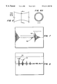
- FIG. 7 is a graphical representation of a sample return signal for a anchor rod flawed, for example, similar to FIG. 4 .
- FIG. 8 is an expanded graphical representation of a portion of the return signal of FIG. 7 .
- FIG. 9 is a graphical representation of a sample return signal for a anchor rod flawed, for example, similar to FIG. 6 .
- FIG. 10 is a partially-schematicized view of a surface-preparation device useful in connection with the present invention.
- FIG. 11 is a plan view of a second device useful for determining, in part, the quality of the surface preparation.
- FIG. 1 illustrates an exemplary equalizer plate 10 .
- anchor rod 14 and guy wires GW the latter intended to connect to and support a metal tower or other type of structure. Because each of guy wires GW attaches to a different location of the tower to be supported, it may experience different wind-related and other forces than those to which the other guy wires GW are subjected. Plate 10 is adapted, at least in part, to “equalize” the effects of these different forces and thus is likely to vibrate during times in which it is in use.
- Rod 14 comprises head end 18 and back end 22 , the former of which is placed in recess 26 of plate 10 . Brazing alloys or other suitable material and any appropriate welding or other technique may be used to connect head end 18 and plate 10 . Typically, however, head end 18 is welded to plate 10 , with full-penetration welds 28 being employed along the sides of head end 18 and fillet welds 30 (see also FIG. 10) used at the top 29 . As a result, rod 14 is relatively rigidly connected to plate 10 with head end 18 inaccessible because of recess 26 and welds 28 and 30 . Although techniques and equipment of the present invention are especially useful in circumstances such as these (particularly when head end 18 is not readily accessible), they may be utilized in other situations as appropriate, including in connection with plates or structures other than equalizer plate 10 .
- rods 14 often are (but need not necessarily be) made of steel approximately ten or fourteen feet long. Certain ten-foot rods 14 have nominal diameter of 1.25 inches, while rods 14 whose nominal length is fourteen feet may have nominal diameter of 1.45 inches. Those skilled in the art will recognize that other rods may be assessed using the innovative techniques and equipment disclosed herein, however.
- Support rod 14 is usually buried below grade G. Without excavating soil surrounding rod 14 , therefore, the majority of it is inaccessible for visual examination.
- Back end 22 may be embedded in reinforced concrete block C underground, rendering it inaccessible for visual review even if excavation occurs.
- FIG. 3 details a possible placement of transducer probe 34 abutting or adjacent top 29 of head end 18 . If top 29 is initially inaccessible, part of weld 30 may be removed to provide access to it. Preferably, the removal process creates a flat surface 38 perpendicular, or nearly so, to the longitudinal axis LA (see FIG. 2) of rod 14 . Transducer probe 34 rests flush with surface 38 , transmitting ultrasonic energy longitudinally through rod 14 . Because the length of rod 14 is substantially greater than its diameter, probe 34 need not necessarily be positioned at the center of top 29 to obtain acceptable results but rather may be placed nearer the circumference of top 29 as, for example, shown in FIG. 3 .
- an acoustic couplant such as Panometrix SWC or boiled bees' honey may coat the portion of surface 38 on which transducer probe 34 is positioned. Probe 34 then is activated to transmit ultrasonic energy longitudinally through rod 14 . Back end 22 typically acts as a reflector, returning at least some of the transmitted energy to probe 34 . Flaws or corrosion present in rod 14 may, however, change or distort the return signals, providing bases for analyzing the integrity of the rod 14 . Such analysis may occur in real-time in the field (if, for example, transducer probe 34 is connected to a computational device) or, if desired, signal data may be stored (electronically, on paper, or otherwise) for subsequent processing remote from the site of the rod 14 .
- surface 38 may be covered or otherwise protected from the ambient environment if necessary or desirable to do so.
- a preferred method for protecting surface 38 in such circumstances is to cover the surface 38 with a sprayable cold-galvanize coating containing zinc. Experimental results using this type of coating indicate that it need not be removed, but rather merely dusted to remove debris, before the next set of transmissions can be satisfactorily made.
- FIGS. 4-6 and 4 A- 6 A diagrammatically illustrate exemplary types of flaws or corrosive effects sometimes encountered with rods 14 .
- FIGS. 4 and 4A show a planar flaw (i.e. one substantially perpendicular to axis LA), such as when rod 14 is cracked or fractured.
- FIGS. 5 and 5A by contrast, illustrate a different type of asymmetrical flaw typical of certain types of corrosion of rod 14 .
- FIGS. 6 and 6A finally, show a symmetrical flaw associated with rod 14 , such as corrosion throughout the circumference of a portion of the length of rod 14 .
- Determining the existence of these types of flaws or corrosion of a rod 14 preferably (although not necessarily) is accomplished with reference to a baseline or prior set of test results. These earlier test results additionally preferably are obtained for each rod 14 before it is used. If obtaining baseline information for each rod 14 prior to use is inappropriate for any reason, however, it alternatively may be done for one or more samples of the type of rod 14 to be used.
- FIG. 7 illustrates generally a sample return, in which signal strength (amplitude) is plotted on the vertical axis as a function of time.
- Discontinuity 42 in the graph is consistent with the existence of a planar flaw in rod 14 similar to that shown in FIGS. 4 and 4A, with the flaw located the majority of the distance of rod 14 away from head end 18 .
- discontinuity 46 represents the effect of return of ultrasonic energy from back end 22
- the position of discontinuity 42 suggests that, in this sample instance, the flaw is located at approximately the point where rod 14 might be embedded below grade in concrete block C.
- FIG. 9 generally details a sample plot associated with wastage of the type shown in FIG. 6 .
- no sharp discontinuity appears as a result of either a planar flaw or energy having been reflected or otherwise returned off back end 22 .
- the wastage has caused sufficient diminishment in the amplitude of the transmitted signal such that inadequate energy remains to be received after being returned from back end 22 to permit recognition of the existence of the back end 22 .
- rod 14 appears incorrectly to be infinitely (or at least indefinitely) long rather than having a defined back end 22 .
- FIG. 8 presents an expanded version of portions of the returned signals of FIG. 7, showing generally the quantity and horizontal spacing of mode-converted return signals.
- Signal set 50 for example, represents the first-arriving longitudinal wavefront, whereas set 54 represents a shear wavefront, etc.
- set 54 represents a shear wavefront, etc.
- regular spacing of the return wavefronts suggests the diameter of rod 14 remains regular along its length, while irregular spacing suggests otherwise.
- Empirical data indicate that, utilizing the methods described herein, planar flaws may be detected with cross-sectional reductions as low as 5%. Radial wastage, whether symmetric or asymmetric, may be detected with cross-sectional losses as low as 20%. In either event, flaw detection is likely before minimum design loads for rods 14 are encountered. In addition to evaluating the structural integrity of the entire lengths and volumes of rods 14 , these techniques may be useful for determining the lengths of the rods 14 , determining the minimum diameters of the rods 14 as a function of their lengths, predicting life expectancies for the rods 14 , and evaluating new rods 14 prior to installation to ensure only sound rods 14 are installed below grade.
- FIG. 10 Shown in FIG. 10 is a device 58 especially adapted for preparing surface 38 for use in accordance with the present invention.
- Device 58 may include motor 62 powered by battery 66 (or another suitable power source), with motor 62 operating to turn cutting tool 70 fitted in chuck 74 .
- Tool 70 contains both side and bottom cutting surfaces 78 and 82 , respectively, to remove any necessary portions of weld 30 and thereby prepare surface 38 .
- Drive assembly 86 contemplated in one version to be a set of shafts cooperating by means of 45° gears, may connect motor 62 and cutting tool 70 (via chuck 74 ).
- Tool 70 is adapted for movement in two dimensions (for convenience referred to as “horizontally” and “vertically”).
- Platform 90 and feed knob 94 cooperate to permit adjustment of the horizontal position of tool 70
- an analogous platform 98 and feed knob 102 permit vertical adjustment of tool 70 .
- Device 58 additionally may be clamped to rod 14 for ease of use, with a self-centering fixture 106 , fixed studs 110 , and anchor nuts 114 being used to effect the clamping.
- a second device 118 may also be used to assess the suitability of preparation of surface 38 .
- Shaped like an inverted “L,” device 118 comprises leg 122 and back 126 , between which a right angle A is defined.
- interior surface 130 of leg 122 should be flush with surface 38 when interior surface 134 of back 126 rests longitudinally along the circumference of rod 14 .
- Leg 122 additionally may have graduations 138 or otherwise be marked to assist in determining whether the width of the prepared surface 38 is sufficient to permit good-quality acoustical coupling of transducer 34 to rod 14 .
- device 118 may be detachably connected to device 58 for ease of transport in the field.
- devices 58 and 118 may be utilized should preparation of surface 38 be necessary.
- devices 58 and 118 may remain useful for this purpose even if modified and thus need not be configured identically as those shown in FIGS. 10-11. Nonetheless, devices 58 and 118 present apparatus particularly adapted for practicing various of the techniques described herein.
Abstract
Description
Claims (12)
Priority Applications (3)
| Application Number | Priority Date | Filing Date | Title |
|---|---|---|---|
| US09/228,336 US6311565B1 (en) | 1999-01-11 | 1999-01-11 | Techniques and equipment for assessing the structural integrity of subterranean tower anchor rods |
| PCT/US2000/000133 WO2000041517A2 (en) | 1999-01-11 | 2000-01-04 | Techniques and equipment for assessing the structural integrity of subterranean tower anchor rods |
| AU24049/00A AU2404900A (en) | 1999-01-11 | 2000-01-04 | Techniques and equipment for assessing the structural integrity of subterranean tower anchor rods |
Applications Claiming Priority (1)
| Application Number | Priority Date | Filing Date | Title |
|---|---|---|---|
| US09/228,336 US6311565B1 (en) | 1999-01-11 | 1999-01-11 | Techniques and equipment for assessing the structural integrity of subterranean tower anchor rods |
Publications (1)
| Publication Number | Publication Date |
|---|---|
| US6311565B1 true US6311565B1 (en) | 2001-11-06 |
Family
ID=22856768
Family Applications (1)
| Application Number | Title | Priority Date | Filing Date |
|---|---|---|---|
| US09/228,336 Expired - Lifetime US6311565B1 (en) | 1999-01-11 | 1999-01-11 | Techniques and equipment for assessing the structural integrity of subterranean tower anchor rods |
Country Status (3)
| Country | Link |
|---|---|
| US (1) | US6311565B1 (en) |
| AU (1) | AU2404900A (en) |
| WO (1) | WO2000041517A2 (en) |
Cited By (10)
| Publication number | Priority date | Publication date | Assignee | Title |
|---|---|---|---|---|
| EP1780539A1 (en) * | 2005-10-26 | 2007-05-02 | Fujimitsu Engineering Co., Ltd. | Method and apparatus for non-destructive ultrasonic testing of concrete structures |
| US20070095139A1 (en) * | 2005-10-27 | 2007-05-03 | Fujimitsu Engineering Co., Ltd. | Method and apparatus for non-destructive testing of concrete structures |
| US20080193224A1 (en) * | 2007-02-13 | 2008-08-14 | Electronics Research, Inc. | Guy anchor equalizer plate with ultrasound port |
| US20080283332A1 (en) * | 2007-05-16 | 2008-11-20 | Jeong-Beom Ihn | Method and system for detecting an anomaly and determining its size |
| US20090032329A1 (en) * | 2007-05-16 | 2009-02-05 | Jeong-Beom Ihn | Imaging an anomaly using backscattered waves |
| US20100040416A1 (en) * | 2006-09-25 | 2010-02-18 | Young Kwon Kang | Method for construction of waste landfills |
| WO2012005792A1 (en) * | 2010-07-06 | 2012-01-12 | American Tower Corporation | Guy anchor reinforcement |
| US20120011780A1 (en) * | 2010-07-13 | 2012-01-19 | Jaime Reyes | Modular guy anchor |
| US8499632B1 (en) | 2010-08-23 | 2013-08-06 | The Boeing Company | Characterizing anomalies in a laminate structure |
| US8534132B1 (en) | 2010-11-19 | 2013-09-17 | Charles L. Purdy | Method for measuring tension in an anchored rod at an accessible end |
Families Citing this family (2)
| Publication number | Priority date | Publication date | Assignee | Title |
|---|---|---|---|---|
| CN111811850B (en) * | 2020-06-28 | 2022-01-18 | 盾构及掘进技术国家重点实验室 | Anchor rod cable system cooperative bearing performance testing device and method |
| CN112051331A (en) * | 2020-09-14 | 2020-12-08 | 哈尔滨全感科技有限公司 | Ultrasonic guided wave transducer support capable of moving along axial direction of cylinder, support device and cylinder detection method |
Citations (16)
| Publication number | Priority date | Publication date | Assignee | Title |
|---|---|---|---|---|
| US3600936A (en) | 1968-04-01 | 1971-08-24 | Vitro Corp Of America | Transceiver ultrasonic image system |
| US3756071A (en) | 1969-06-06 | 1973-09-04 | Realisations Ultrasoniques Sa | Process and apparatus for analyzing materials by means of ultrasonic pulses, employing the transfer function characteristic of each obstacle |
| US3877294A (en) | 1972-04-11 | 1975-04-15 | Fanner Manufacturing Company P | Vibration technique for rot detection in wood poles and trees |
| US4281547A (en) | 1979-05-10 | 1981-08-04 | Conoco, Inc. (Formerly Continental Oil Company) | Electronic mine roof bolt tester |
| US4285993A (en) * | 1979-03-30 | 1981-08-25 | Green Sr John H | Anti-corrosive structure anchor assembly |
| US4350044A (en) | 1979-12-19 | 1982-09-21 | Yorkshire Electricity Board | Method of and apparatus for testing wooden poles |
| US4380930A (en) * | 1981-05-01 | 1983-04-26 | Mobil Oil Corporation | System for transmitting ultrasonic energy through core samples |
| US4750117A (en) * | 1984-12-13 | 1988-06-07 | Surface Systems, Inc. | Ultrasonic depth measurement apparatus and methods |
| US4858469A (en) | 1986-09-20 | 1989-08-22 | Bio-Kil Chemicals Limited | Method and apparatus for testing timbers for disconformity or decay |
| US4904122A (en) * | 1987-08-06 | 1990-02-27 | Dyckerhoff & Widmann Aktiengesellschaft | Anchoring device, such as a rock anchor |
| US5000045A (en) * | 1989-12-21 | 1991-03-19 | Ford Aerospace Corporation | Acoustic emission waveguide |
| US5286142A (en) * | 1993-03-22 | 1994-02-15 | A. B. Chance Company | Reduced moment anchor hub |
| US5475613A (en) | 1991-04-19 | 1995-12-12 | Kawasaki Jukogyo Kabushiki Kaisha | Ultrasonic defect testing method and apparatus |
| US5571966A (en) | 1993-10-12 | 1996-11-05 | Iwatsu Electric Co., Ltd. | Method and apparatus for predicting lifetime of measured object |
| US5675085A (en) | 1994-10-28 | 1997-10-07 | H & B System Inc. | Method and apparatus for measuring depth of crack for reinforced concrete construction |
| US5760308A (en) | 1994-09-07 | 1998-06-02 | The Regents Of The University Of California | Method and apparatus for non-destructively detecting hidden defects caused by bio-deterioration in living trees and round wood materials |
Family Cites Families (1)
| Publication number | Priority date | Publication date | Assignee | Title |
|---|---|---|---|---|
| GB9406745D0 (en) * | 1994-04-06 | 1994-05-25 | Aberdeen University And Univer | Integrity assessment of ground anchorages |
-
1999
- 1999-01-11 US US09/228,336 patent/US6311565B1/en not_active Expired - Lifetime
-
2000
- 2000-01-04 AU AU24049/00A patent/AU2404900A/en not_active Abandoned
- 2000-01-04 WO PCT/US2000/000133 patent/WO2000041517A2/en active Application Filing
Patent Citations (16)
| Publication number | Priority date | Publication date | Assignee | Title |
|---|---|---|---|---|
| US3600936A (en) | 1968-04-01 | 1971-08-24 | Vitro Corp Of America | Transceiver ultrasonic image system |
| US3756071A (en) | 1969-06-06 | 1973-09-04 | Realisations Ultrasoniques Sa | Process and apparatus for analyzing materials by means of ultrasonic pulses, employing the transfer function characteristic of each obstacle |
| US3877294A (en) | 1972-04-11 | 1975-04-15 | Fanner Manufacturing Company P | Vibration technique for rot detection in wood poles and trees |
| US4285993A (en) * | 1979-03-30 | 1981-08-25 | Green Sr John H | Anti-corrosive structure anchor assembly |
| US4281547A (en) | 1979-05-10 | 1981-08-04 | Conoco, Inc. (Formerly Continental Oil Company) | Electronic mine roof bolt tester |
| US4350044A (en) | 1979-12-19 | 1982-09-21 | Yorkshire Electricity Board | Method of and apparatus for testing wooden poles |
| US4380930A (en) * | 1981-05-01 | 1983-04-26 | Mobil Oil Corporation | System for transmitting ultrasonic energy through core samples |
| US4750117A (en) * | 1984-12-13 | 1988-06-07 | Surface Systems, Inc. | Ultrasonic depth measurement apparatus and methods |
| US4858469A (en) | 1986-09-20 | 1989-08-22 | Bio-Kil Chemicals Limited | Method and apparatus for testing timbers for disconformity or decay |
| US4904122A (en) * | 1987-08-06 | 1990-02-27 | Dyckerhoff & Widmann Aktiengesellschaft | Anchoring device, such as a rock anchor |
| US5000045A (en) * | 1989-12-21 | 1991-03-19 | Ford Aerospace Corporation | Acoustic emission waveguide |
| US5475613A (en) | 1991-04-19 | 1995-12-12 | Kawasaki Jukogyo Kabushiki Kaisha | Ultrasonic defect testing method and apparatus |
| US5286142A (en) * | 1993-03-22 | 1994-02-15 | A. B. Chance Company | Reduced moment anchor hub |
| US5571966A (en) | 1993-10-12 | 1996-11-05 | Iwatsu Electric Co., Ltd. | Method and apparatus for predicting lifetime of measured object |
| US5760308A (en) | 1994-09-07 | 1998-06-02 | The Regents Of The University Of California | Method and apparatus for non-destructively detecting hidden defects caused by bio-deterioration in living trees and round wood materials |
| US5675085A (en) | 1994-10-28 | 1997-10-07 | H & B System Inc. | Method and apparatus for measuring depth of crack for reinforced concrete construction |
Non-Patent Citations (3)
| Title |
|---|
| F. Langebrake, et al., "Non-destructive Testing of Ground-Anchors of Bridge Structures," International Symposium Non-Destructive Testing in Civil Engineering (NDT-CE), Sep. 26-28, 1995, pp. 453-458. |
| G. Niles, "In Situ Method of Inspecting Anchor Rods for Section Loss Using the Cylindrically Guided Wave Technique," IEEE Transactions on Power Delivery, vol. 11, No. 3, Jul. 1996, pp. 1601-1605. |
| K. Boney, "Getting a Grip on Towers," Cellular Business, Dec. 1995, pp. 42, 46, 48, 52. |
Cited By (20)
| Publication number | Priority date | Publication date | Assignee | Title |
|---|---|---|---|---|
| EP1780539A1 (en) * | 2005-10-26 | 2007-05-02 | Fujimitsu Engineering Co., Ltd. | Method and apparatus for non-destructive ultrasonic testing of concrete structures |
| US20070095139A1 (en) * | 2005-10-27 | 2007-05-03 | Fujimitsu Engineering Co., Ltd. | Method and apparatus for non-destructive testing of concrete structures |
| US20100040416A1 (en) * | 2006-09-25 | 2010-02-18 | Young Kwon Kang | Method for construction of waste landfills |
| US20080193224A1 (en) * | 2007-02-13 | 2008-08-14 | Electronics Research, Inc. | Guy anchor equalizer plate with ultrasound port |
| US7827741B2 (en) * | 2007-02-13 | 2010-11-09 | Electronics Research, Inc. | Guy anchor equalizer plate with ultrasound port |
| US20080283332A1 (en) * | 2007-05-16 | 2008-11-20 | Jeong-Beom Ihn | Method and system for detecting an anomaly and determining its size |
| WO2008144356A1 (en) * | 2007-05-16 | 2008-11-27 | The Boeing Company | Method and system for detecting an anomaly and determing its size |
| US20090032329A1 (en) * | 2007-05-16 | 2009-02-05 | Jeong-Beom Ihn | Imaging an anomaly using backscattered waves |
| US7891247B2 (en) * | 2007-05-16 | 2011-02-22 | The Boeing Company | Method and system for detecting an anomaly and determining its size |
| US8015877B2 (en) | 2007-05-16 | 2011-09-13 | The Boeing Company | Imaging an anomaly using backscattered waves |
| WO2012005792A1 (en) * | 2010-07-06 | 2012-01-12 | American Tower Corporation | Guy anchor reinforcement |
| US8250817B2 (en) | 2010-07-06 | 2012-08-28 | American Tower Corporation | Guy anchor reinforcement |
| US8458986B2 (en) | 2010-07-06 | 2013-06-11 | Atc Ip Llc | Guy anchor reinforcement |
| AU2011277062B2 (en) * | 2010-07-06 | 2014-05-15 | Atc Ip Llc | Guy anchor reinforcement |
| US8745933B2 (en) | 2010-07-06 | 2014-06-10 | Atc Ip Llc | Guy anchor reinforcement |
| US20120011780A1 (en) * | 2010-07-13 | 2012-01-19 | Jaime Reyes | Modular guy anchor |
| US8375651B2 (en) * | 2010-07-13 | 2013-02-19 | Atc Ip Llc | Modular guy anchor |
| US8578665B2 (en) * | 2010-07-13 | 2013-11-12 | Atc Ip Llc | Modular guy anchor |
| US8499632B1 (en) | 2010-08-23 | 2013-08-06 | The Boeing Company | Characterizing anomalies in a laminate structure |
| US8534132B1 (en) | 2010-11-19 | 2013-09-17 | Charles L. Purdy | Method for measuring tension in an anchored rod at an accessible end |
Also Published As
| Publication number | Publication date |
|---|---|
| WO2000041517A2 (en) | 2000-07-20 |
| AU2404900A (en) | 2000-08-01 |
| WO2000041517A3 (en) | 2002-05-02 |
Similar Documents
| Publication | Publication Date | Title |
|---|---|---|
| US6311565B1 (en) | Techniques and equipment for assessing the structural integrity of subterranean tower anchor rods | |
| Wilcox et al. | Guided wave testing of rail | |
| Alleyne et al. | Rapid, long range inspection of chemical plant pipework using guided waves | |
| US7827741B2 (en) | Guy anchor equalizer plate with ultrasound port | |
| Ciolko et al. | Nondestructive methods for condition evaluation of prestressing steel strands in concrete bridges | |
| JP2004361321A (en) | Defect evaluating apparatus of underground structure, defect evaluating method and program for making computer execute the same | |
| JP4753241B2 (en) | Nondestructive inspection method and inspection apparatus for the degree of corrosion of reinforcing bars in concrete structures by ultrasonic method | |
| JP3198840U (en) | Prop road boundary inspection system | |
| Dingus et al. | Nondestructive, noninvasive assessment of underground pipelines | |
| JP2003021621A (en) | Corrosion diagnosing system | |
| US20020148293A1 (en) | Method and apparatus for the measurement of corrosion and damage in installed bolts, rods and bars | |
| EP1882923A3 (en) | Method and apparatus for ultrasonic inspection of steel pipes | |
| Baraneedaran et al. | Review of in-service assessment of timber poles | |
| Demma et al. | Testing of buried pipelines using guided waves | |
| JP2000002692A (en) | Method for searching defect in concrete structure or behind the structure | |
| Schultz et al. | Acoustic Emission Monitoring of a Fracture-Critical Bridge | |
| Rudlin et al. | Inspection reliability and periodicity for rail axle inspection | |
| US11175263B2 (en) | Apparatus and method for generating, measuring, and evaluating vibrational modes in cylindrical objects | |
| Newton | The transparency of fatigue cracks to NDT methods used for the inspection of offshore structures | |
| Foley | Fatigue Risks in the Connections of Sign Support Structures: Phase 1 | |
| JP2002071650A (en) | Method of ultrasonic flaw detection for hollow concrete column | |
| JP7164953B2 (en) | Non-destructive diagnosis method for protective fences | |
| Belivanis | Assessment of remaining fatigue performance of high mast illumination poles | |
| Romero et al. | Inspection of lamp posts and other non-accessible areas with EMAT Medium-Range Guided Waves | |
| Kania et al. | Investigation and Assessment of Low-Frequency ERW Seam Imperfections by EMAT and CMFL ILI |
Legal Events
| Date | Code | Title | Description |
|---|---|---|---|
| AS | Assignment |
Owner name: WESTINGHOUSE SAVANNAH RIVER COMPANY, SOUTH CAROLIN Free format text: ASSIGNMENT OF ASSIGNORS INTEREST;ASSIGNORS:HINZ, WILLIAM R.;PARKER, MATTHEW J.;REEL/FRAME:009700/0834 Effective date: 19990106 |
|
| STCF | Information on status: patent grant |
Free format text: PATENTED CASE |
|
| FPAY | Fee payment |
Year of fee payment: 4 |
|
| AS | Assignment |
Owner name: WASHINGTON SAVANNAH RIVER COMPANY LLC, SOUTH CAROL Free format text: CHANGE OF NAME;ASSIGNOR:WESTINGHOUSE SAVANNAH RIVER COMPANY LLC;REEL/FRAME:021281/0813 Effective date: 20051208 |
|
| AS | Assignment |
Owner name: SAVANNAH RIVER NUCLEAR SOLUTIONS, LLC, SOUTH CAROL Free format text: ASSIGNMENT OF ASSIGNORS INTEREST;ASSIGNOR:WASHINGTON SAVANNAH RIVER COMPANY LLC;REEL/FRAME:021838/0626 Effective date: 20081023 |
|
| FPAY | Fee payment |
Year of fee payment: 8 |
|
| AS | Assignment |
Owner name: WESTINGHOUSE SAVANNAH RIVER COMPANY LLC, SOUTH CAR Free format text: CHANGE OF NAME;ASSIGNOR:WESTINGHOUSE SAVANNAH RIVER COMPANY, INC.;REEL/FRAME:023679/0288 Effective date: 19990322 |
|
| FPAY | Fee payment |
Year of fee payment: 12 |