US6304405B1 - Method and apparatus for controlling read and/or write operations of a disk drive device during start-up - Google Patents
Method and apparatus for controlling read and/or write operations of a disk drive device during start-up Download PDFInfo
- Publication number
- US6304405B1 US6304405B1 US09/115,158 US11515898A US6304405B1 US 6304405 B1 US6304405 B1 US 6304405B1 US 11515898 A US11515898 A US 11515898A US 6304405 B1 US6304405 B1 US 6304405B1
- Authority
- US
- United States
- Prior art keywords
- data
- rotational speed
- recording disk
- data recording
- read
- Prior art date
- Legal status (The legal status is an assumption and is not a legal conclusion. Google has not performed a legal analysis and makes no representation as to the accuracy of the status listed.)
- Expired - Fee Related
Links
Images


Classifications
-
- G—PHYSICS
- G11—INFORMATION STORAGE
- G11B—INFORMATION STORAGE BASED ON RELATIVE MOVEMENT BETWEEN RECORD CARRIER AND TRANSDUCER
- G11B19/00—Driving, starting, stopping record carriers not specifically of filamentary or web form, or of supports therefor; Control thereof; Control of operating function ; Driving both disc and head
- G11B19/20—Driving; Starting; Stopping; Control thereof
-
- G—PHYSICS
- G11—INFORMATION STORAGE
- G11B—INFORMATION STORAGE BASED ON RELATIVE MOVEMENT BETWEEN RECORD CARRIER AND TRANSDUCER
- G11B25/00—Apparatus characterised by the shape of record carrier employed but not specific to the method of recording or reproducing, e.g. dictating apparatus; Combinations of such apparatus
- G11B25/04—Apparatus characterised by the shape of record carrier employed but not specific to the method of recording or reproducing, e.g. dictating apparatus; Combinations of such apparatus using flat record carriers, e.g. disc, card
- G11B25/043—Apparatus characterised by the shape of record carrier employed but not specific to the method of recording or reproducing, e.g. dictating apparatus; Combinations of such apparatus using flat record carriers, e.g. disc, card using rotating discs
Definitions
- the present invention relates to a method and apparatus to reduce the time period from a power on status to a ready status of a hard disk drive device.
- FIG. 1 is a flow chart describing the operation of a conventional hard disk drive device.
- the operation starts at step 1 in which a power-on reset (POR) operation is performed in response to the power on of the hard disk drive device.
- POR power-on reset
- an MPU contained in the hard disk drive device starts its operation by using control programs stored in its read-only memory (ROM).
- ROM read-only memory
- step 3 the rotation of a spindle motor which is coupled to a magnetic recording disk is started.
- the MPU determines whether or not the rotational speed of the spindle motor and the magnetic recording disk reach a final rotational speed, for example 7200 rpm.
- step 3 If the final rotational speed is not met, then the operation returns to step 3 , otherwise, the operation proceeds to step 5 in which a supporting arm for supporting a head/slider assembly is moved from a rest position to a position above a data track of the magnetic recording disk by a voice coil motor.
- control programs stored in special data tracks (i.e., outside the data tracks used during normal read/write operations) on the magnetic recording disk are read and stored in random access memory (RAM), and the MPU sends a ready signal to a host processor.
- the hard disk drive device waits for a command from the host processor.
- the amount of time for a conventional hard disk drive device to perform the steps described in steps 1 - 6 is relatively long, for example 10 seconds.
- the steps described in steps 1 - 4 require about 90% of the total time to transition from the power-on status to the ready status.
- An object of the present invention is to reduce the amount of time from a power-on status to a ready status of a hard disk drive device.
- a method of controlling read and/or write operations of a disk drive device during start-up is described. After power-up, the rotational speed of a data recording disk is increased. When it is detected that the rotational speed of the data recording disk is rotating at a first rotational speed, a control program recorded on the data recording disk is read and then stored in a memory device. Additionally, a ready signal is sent to a host processor. Furthermore, while rotating the data recording disk at the first rotational speed, a read command is received from the host processor to perform a read operation. The rotational speed of the data recording disk is then increased to a second rotational speed. While rotating the data recording disk at the second rotational speed a read operation and/or write operation is performed.
- data is read from the data recording disk. Furthermore, it is determined whether or not the data read contains an error. If the data read does not contain an error, data is then transferred to the host processor. If the data read does contain an error, the data is reread from the data recording disk when performing the read operation while the data recording disk is rotating at the second rotational speed.
- a write command is received while the data recording disk is rotating at the first rotational speed.
- Write data is then stored in the memory device and a write command completion signal is sent to the host processor.
- the data stored in the memory device is recorded on the data recording disk while the data recording disk is rotating at the second rotational speed.
- the disk drive device includes a data recording disk and a spindle motor operable to support and rotate the data recording disk. Additionally, the disk drive device includes a head/slider assembly for reading data from and writing data to the data recording disk and a voice coil motor operable to position the head/slider assembly with respect to the data recording disk.
- the disk drive device also includes a memory device and a control unit. The control unit is operable to read a control program from the data recording disk, store it on the memory device, provide a ready signal to a host processor and perform a read operation while controlling the rotation of the spindle motor at a first rotational speed. If a data error is detected from the read operation, the read operation is retried while controlling the rotation of the spindle motor at a second rotational speed which is faster than the first rotational speed.
- control circuit is further operable to store write data from the host processor in the memory device while controlling the rotation of the spindle motor at the first rotational speed.
- control circuit is further operable to write the data stored in the memory device onto the data recording disk while controlling the rotation of the spindle motor at the second rotational speed.
- FIG. 1 shows the steps for transitioning a conventional hard disk drive device from a power-on status to a ready status
- FIG. 2 shows a hard disk drive device in accordance with one embodiment of the present invention
- FIGS. 3, 4 , and 5 show the steps for transitioning a hard disk drive device in accordance with one embodiment of the present invention from a power-on status to a ready status;
- FIG. 6A shows a timing diagram for transitioning a hard disk drive device in accordance with one embodiment of the present invention from a power-on status to a ready status
- FIG. 6B shows a timing diagram for transitioning a hard disk drive device in accordance with another embodiment of the present invention from a power-on status to a ready status
- FIG. 6C shows a timing diagram for transitioning the conventional hard disk drive device from a power-on status to a ready status
- FIGS. 7, and 8 show the steps for transitioning a hard disk drive device in accordance with another embodiment of the present invention from a power-on status to a ready status.
- FIG. 2 shows a block diagram of a hard disk drive device in accordance with one embodiment of the present invention.
- a recording surface of a magnetic recording disk or a rotating recording disk 10 is divided into an area 10 A containing special recording tracks for recording control programs and an area 10 B containing data tracks accessed in a normal read/write operation.
- the magnetic recording disk 10 is rotated by a spindle motor 13 .
- a supporting arm 19 for supporting a head/slider assembly 9 is moved in a radial direction of the magnetic recording disk 10 by a voice coil motor (VCM) 11 .
- VCM voice coil motor
- the spindle motor 13 and the VCM 11 are controlled by a VCM/spindle driver 14 .
- a read/write circuit 12 is coupled to a head to control the read/write operation of the data.
- a hard disk control circuit 15 is coupled to the read/write circuit 12 , VCM/spindle driver 14 and a memory 17 .
- the memory 17 includes a data area 17 A for storing data during a normal read/write operation when the magnetic recording disk 10 is rotated at a designated rotational speed, such as 7200 rpm, which is referred to as a final rotational speed.
- the memory 17 also includes a RAM area 17 B which is used to store the control program down loaded from the special tracks in the area 10 A of the magnetic recording disk 10 , and a buffer 17 C which operates as a cache buffer for storing data sent from a host processor 18 to be subsequently described with respect to block 37 in the FIG. 5 and block 57 in the FIG. 8 .
- a main control circuit or MPU 16 controls the operation of VCM/spindle driver 14 , hard disk control circuit 15 and memory 17 .
- the hard disk control circuit 15 is coupled to host processor 18 through an interface 20 .
- FIGS. 3, 4 and 5 show flow chart for describing the operation of a first embodiment of the present invention controlled by MPU 16 .
- the operation starts at step 21 .
- a power-on-reset (POR) is performed.
- POR power-on-reset
- MPU 16 starts its operation by using control programs stored in a ROM (Read Only Memory) 16 A in MPU 16 .
- the operation proceeds to step 23 where the rotation of spindle motor 13 is started.
- the rotational speed of spindle motor 13 and magnetic recording disk 10 is increased from 0 rpm to 7200 rpm.
- 7200 represents the final rotational speed.
- head/slider assembly 9 starts to fly above the surface of magnetic recording disk 10 .
- the following two intermediate rotational speeds may be selected:
- the first intermediate rotational speed (e.g., 4500 rpm) is selected because at this speed of the data recorded on the disk 10 can be read.
- step 24 MPU 16 determines whether or not the rotational speed of spindle motor 13 and magnetic recording disk 10 reaches the first intermediate rotational speed, e.g., 4500 rpm. If the answer to step 24 is “NO”, the operation returns to step 23 . If the answer to step 24 is “YES”, the operation proceeds to a step 25 in which MPU 16 and VCM/spindle driver 14 fix the rotational speed of disk 10 at the first intermediate rotational speed (4500 rpm), and MPU 16 and VCM/spindle driver 14 control VCM 11 to move the supporting arm 19 for supporting head/slider assembly 9 from a rest position to a position above the special recording tracks in area 10 A.
- MPU 16 and VCM/spindle driver 14 fix the rotational speed of disk 10 at the first intermediate rotational speed (4500 rpm)
- MPU 16 and VCM/spindle driver 14 control VCM 11 to move the supporting arm 19 for supporting head/slider assembly 9 from a rest position to a position above the special recording
- the spindle motor 13 is a three phase AC motor.
- a pulse train induced by the rotation of the three phase coils of spindle motor 13 synchronous with the rotational speed is detected by a detecting device, not shown in the drawing.
- the detecting device supplies the pulse train to the 16 .
- the MPU 16 monitors the pulse train to determine the rotational speed of spindle motor 13 .
- step 26 MPU 16 reads one or more control programs recorded in the special data tracks in area 10 A on magnetic recording disk 10 and stores them in a RAM 17 B of memory 17 .
- the MPU 16 sends a ready signal to host processor 18 .
- control program used for starting the operation of MPU 16 and for starting the rotation of spindle motor 13 is stored in ROM 16 A, and the remaining portion of the control program is stored in the special data tracks in area 10 A.
- the control programs stored in the special data tracks are down loaded to RAM 17 B in memory 17 , as described before.
- step 27 in FIG. 4 MPU 16 determines whether or not a read command from host processor 18 is received within some interval, for example a 1 second interval. If the answer to step 27 is “YES”, the operation proceeds to step 28 A in which data specified by the read command is read from the magnetic recording disk 10 . The operation proceeds to step 28 B in which MPU 16 determines whether or not the read data contains an error. If the answer to step 28 B is “NO”, the operation proceeds to step 28 C in which the read data is transferred to host processor 18 through interface 20 .
- step 28 B If the answer to step 28 B is “YES”, then the data read at the first rotational speed (e.g., 4500 rpm) contains an error, and the operation proceeds to step 28 D in which MPU 16 increases the rotational speed of disk 10 to the second intermediate rotational speed (e.g., 5400 rpm). The operation proceeds to step 28 E in which MPU 16 determines whether or not the read data contains an error. If the answer to step 28 E is “NO”, the operation proceeds to step 28 F in which the read data is transferred to host processor 18 through interface 20 .
- the first rotational speed e.g., 4500 rpm
- step 28 E If the answer to step 28 E is “YES”, then the data read at the second rotational speed (e.g., 5400 rpm) contains an error, and the operation proceeds to step 28 G in which the operation proceeds to step 40 , and the read operation of the data is retried during the normal read/write operation (e.g., 7200 rpm).
- the normal read/write operation e.g., 7200 rpm
- step 27 If the answer to step 27 is “NO”, the operation proceeds to step 29 in which MPU 16 determines whether or not a write command from host processor 18 is received. If the answer to step 29 is “YES”, the operation proceeds to step 37 in which MPU 16 temporarily stores or caches the data sent from host processor 18 in buffer 17 C of memory 17 , and sends back a command completion signal to host processor 18 . The operation then proceeds to step 38 to be subsequently described below.
- step 29 If the answer to step 29 is “NO”, the operation proceeds to step 30 in which MPU 16 and VCM/spindle driver 14 increase the rotational speed of disk 10 , now at the first intermediate rotational speed (e.g., 4500 rpm).
- first intermediate rotational speed e.g. 4500 rpm
- step 31 MPU 16 determines whether or not the rotational speed of disk 10 reaches the second rotational speed (e.g., 5400 rpm). If the answer to step 31 is “NO”, the operation returns to step 30 . If the answer to step 31 is “YES”, the operation proceeds to step 32 in which MPU 16 and VCM/spindle driver 14 fix the rotational speed of disk 10 at the second rotational speed (e.g., 5400 rpm).
- step 33 shown in FIG. 5 MPU 16 determines whether or not a read command from host processor 18 is received within some interval, for example, a 1 second interval.
- step 34 A data specified by the read command is read from magnetic recording disk 10 .
- step 34 B MPU 16 determines whether or not the read data contains an error. If the answer to step 34 B is “NO”, the operation proceeds to step 34 C in which the read data is transferred to host processor 18 through interface 20 . If the answer to step 34 B is “YES”, then the data read at the second intermediate rotational speed (e.g., 5400 rpm) contains an error, and the operation proceeds to step 34 D in which the operation proceeds to step 40 and MPU 16 retries the read operation based upon the current read command in the normal read/write operation.
- the second intermediate rotational speed e.g., 5400 rpm
- the read operation is retried during the normal read/write operation at which disk 10 is rotated at the final rotational speed (e.g., 7200 rpm).
- step 33 the operation proceeds to step 35 in which MPU 16 determines whether or not a write command from host processor 18 is received. If the answer to step 35 is “YES”, the operation proceeds to step 37 in which MPU 16 temporarily stores the data sent from host processor 18 in buffer 17 C of memory 17 , and sends back a command completion signal to host processor 18 .
- the operation proceeds to block 38 in which MPU 16 and VCM/spindle driver 14 increase the rotational speed of disk 10 , now at the second intermediate rotational speed (e.g., 5400 rpm) toward the normal or final rotational speed (e.g., 7200 rpm).
- step 39 MPU 16 determines whether or not the rotational speed of disk 10 reaches the final rotational speed (e.g., 7200 rpm). If the answer to step 39 is “NO”, the operation returns back to the step 38 . If the answer to step 39 is “YES”, the operation proceeds to step 40 in which the normal read/write operation at the normal or final rotational speed (e.g., 7200 rpm) is started.
- the normal read/write operation at the normal or final rotational speed e.g., 7200 rpm
- step 37 If the data is stored in buffer 17 C as specified in step 37 , the write operation of the cached data in the buffer 17 C is performed during the normal read/write operation.
- FIG. 6 (A) shows the timing diagram of the operational sequences of the first embodiment of the present invention described with reference to FIGS. 3, 4 , and 5 ;
- FIG. 6 (B) shows the timing diagram of the operational sequence of the second embodiment of the present invention, to be subsequently described with reference to FIGS. 3, 7 and 8 ;
- FIG. 6 (C) shows the timing diagram of the operational sequence of the conventional hard disk drive described with reference to FIG. 1 .
- MPU 16 when the write command and the data from host processor 18 are received during a period between the start of the ready status and the start of the normal read/write operation, MPU 16 sends the command completion signal to host processor 18 , but the data is stored or cached in buffer 17 C, and the actual write operation of the data to disk 10 is not performed during this period.
- the actual write operation of the data is performed during the normal read/write operation in which disk 10 is rotated at the final rotational speed (e.g., 7200 rpm).
- the hard disk drive device is generally designed to write data at the final rotational speed (e.g., 7200 rpm) and to read data at the final rotational speed. Accordingly, a probability of an error while reading, at the final rotational speed (e.g., 7200 rpm), the data which is written at the final rotational speed (e.g., 7200 rpm) is relatively low, while a probability of an error while reading, at the normal rotational speed (e.g., 7200 rpm), the data which is written at the intermediate rotational speed (e.g., 4500 rpm or 5400 rpm) is remarkably high. Therefore, the actual write operation is not performed before the normal read/write operation.
- the final rotational speed e.g., 7200 rpm
- the intermediate rotational speed e.g., 4500 rpm or 5400 rpm
- the read operation requested by the read command received during the period between the start of the ready status and the start of the normal read/write operation is performed during the period at which disk 10 is rotated at the intermediate rotational speed (e.g., 4500 rpm or 5400 rpm).
- the read operation is performed before the normal read/write operation for the following reason. Because the hard disk drive device is generally designed to write the data at the final rotational speed (e.g., 7200 rpm) and to read the data at the final rotational speed, an error may occur when the data is read from disk 10 at the intermediate rotational speed (e.g., 4500 rpm or 5400 rpm). As described above, however, one or more chances for retrying the read operation is provided in the present invention. More particularly, even if an error is detected in step 28 B during the read operation performed at the first intermediate rotational speed (e.g., 4500 rpm), the read operation can be retried at the next rotational speed, (e.g., 5400 rpm).
- the intermediate rotational speed e.g., 4500 rpm
- the read operation can be retried at the next rotational speed, for example the final rotational speed (e.g., 7200 rpm) during the normal read/write operation.
- the final rotational speed e.g. 7200 rpm
- FIG. 6 shows that the time periods from the power-on status to the start of the ready status in the first and second embodiments of the present invention shown in FIGS. 6 (A) and 6 (B), respectively, is substantially reduced in comparison with that in the conventional disk drive device shown in FIG. 6 (C).
- FIGS. 3, 7 and 8 show a flow chart for describing the operation of the second embodiment of the present invention controlled by MPU 16 .
- Step 26 shown in FIG. 3 is followed by step 51 shown in FIG. 7 in which MPU 16 and VCM/spindle driver 14 increase the rotational speed of disk 10 now rotated at the first intermediate rotational speed (e.g., 4500 rpm) toward the final rotational speed (e.g., 7200 rpm).
- the operation proceeds to step 52 in which MPU 16 determines whether or not the read command from the host processor is received. If the answer to step 52 is “NO”, the operation proceeds to step 56 shown in FIG. 8 . If the answer to step 52 is “YES”, the operation proceeds to step 53 in which the data is read from disk 10 .
- the operation proceeds to step 54 in which MPU 16 determines whether or not the data contains an error.
- step 54 If the answer to step 54 is “NO”, the operation proceeds to step 55 in which the data is transferred to host processor 18 . If the answer to step 54 is “YES”, the operation proceeds to step 54 A in which a count value indicating the number of occurrence of the answer “YES” from step 54 is incremented. It is noted that the count value in step 54 A is reset to zero during step 21 shown in the FIG. 3 .
- step 54 B MPU 16 determines whether or not the count value of step 54 A exceeds a predetermined value “X”. If the answer to step 54 B is “NO”, the operation returns to step 53 . If the answer to step 54 B is “YES”, the operation proceeds to step 54 C in which the operation proceeds to step 59 , and MPU 16 retries the read operation based upon the current read command in the normal read/write operation. It indicates that if the data read during the increase of the rotational speed of disk 10 contains an error, the read operation is retried during the normal read/write operation at which the disk 10 is rotated at the final rotational speed (e.g., 7200 rpm).
- the final rotational speed e.g., 7200 rpm
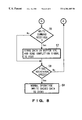
- step 55 After the data has been sent to host processor 18 in step 55 , the operation proceeds to step 56 shown in FIG. 8 in which MPU 16 determines whether or not a write command from the host processor 18 is received. If the answer to step 56 is “YES”, the operation proceeds to step 57 in which MPU 16 temporarily stores or caches the data sent from host processor 18 in buffer 17 C of memory 17 , and sends back a command completion signal to host processor 18 .
- step 58 The operation proceeds to step 58 . If the answer to step 56 is “NO”, the operation also proceeds to step 58 in which MPU 16 determines whether or not the rotational speed of disk 10 reaches the final rotational speed (e.g., 7200 rpm). If the answer to step 58 is “NO”, the operation returns to step 51 . If the answer to step 58 is “YES”, the operation proceeds to step 59 in which the normal read/write operation at the final rotational speed (e.g., 7200 rpm) is started. If the data is stored in buffer 17 C specified in step 57 , the write operation of the cached data in buffer 17 C is performed during the normal read/write operation.
- the final rotational speed e.g., 7200 rpm
- a single bit of data can be represented by a plurality of bits.
- a bit “1” is represented by a plurality of bits, such as three bits “111”.
- Another way for increasing the capability of the error correction is to increase the number of error correction bits attached to the data bits.
Landscapes
- Rotational Drive Of Disk (AREA)
- Signal Processing For Digital Recording And Reproducing (AREA)
Abstract
Description
Claims (16)
Applications Claiming Priority (2)
| Application Number | Priority Date | Filing Date | Title |
|---|---|---|---|
| JP9-188751 | 1997-07-14 | ||
| JP18875197A JP3396402B2 (en) | 1997-07-14 | 1997-07-14 | Disk drive device and control method therefor |
Publications (1)
| Publication Number | Publication Date |
|---|---|
| US6304405B1 true US6304405B1 (en) | 2001-10-16 |
Family
ID=16229142
Family Applications (1)
| Application Number | Title | Priority Date | Filing Date |
|---|---|---|---|
| US09/115,158 Expired - Fee Related US6304405B1 (en) | 1997-07-14 | 1998-07-14 | Method and apparatus for controlling read and/or write operations of a disk drive device during start-up |
Country Status (2)
| Country | Link |
|---|---|
| US (1) | US6304405B1 (en) |
| JP (1) | JP3396402B2 (en) |
Cited By (12)
| Publication number | Priority date | Publication date | Assignee | Title |
|---|---|---|---|---|
| US20010028608A1 (en) * | 2000-03-17 | 2001-10-11 | Hiroshi Sugimoto | Drive, method for reading data, information recording medium reproduction apparatus, and method for reproducing data |
| US20020191328A1 (en) * | 1998-08-20 | 2002-12-19 | Hitachi, Ltd. | Magnetic disk drive |
| US6549973B1 (en) * | 1999-06-14 | 2003-04-15 | Hitachi Global Storage Technologies The Netherlands B.V. | Method and apparatus for predicting recovery time of hard disk drive |
| US20030126427A1 (en) * | 2002-01-03 | 2003-07-03 | Samsung Electronics Co., Ltd. | Computer system and method for booting up the same |
| US6741414B1 (en) * | 1999-06-15 | 2004-05-25 | Tokyo Electron Limited | Joint spindle speed and head position control in rotating media storage systems |
| US6788488B2 (en) * | 2001-01-22 | 2004-09-07 | Qualcomm, Incorporated | Variable mode multi-media data object storage device |
| US20050177841A1 (en) * | 2002-04-10 | 2005-08-11 | Matushita Elec. Ind. Co. Ltd. | Disk apparatus |
| US20050200999A1 (en) * | 2004-03-11 | 2005-09-15 | Rohm Co., Ltd. | Floppy disk control circuit and floppy disk apparatus |
| US20070168606A1 (en) * | 2006-01-17 | 2007-07-19 | Kabushiki Kaisha Toshiba | Storage device using nonvolatile cache memory and control method thereof |
| US20070250662A1 (en) * | 2006-04-21 | 2007-10-25 | Kabushiki Kaisha Toshiba | Storage device using nonvolatile cache memory and control method thereof |
| US8417839B1 (en) * | 2011-01-06 | 2013-04-09 | Seagate Technology Llc | Concurrent actions for data storage |
| US9373349B1 (en) * | 2015-05-29 | 2016-06-21 | Seagate Technology Llc | Relaxing media design constraints with two-dimensional magnetic recording |
Families Citing this family (1)
| Publication number | Priority date | Publication date | Assignee | Title |
|---|---|---|---|---|
| KR20030008516A (en) * | 2001-07-18 | 2003-01-29 | 삼성전자 주식회사 | computer and control method thereof |
Citations (3)
| Publication number | Priority date | Publication date | Assignee | Title |
|---|---|---|---|---|
| US5345347A (en) * | 1992-02-18 | 1994-09-06 | Western Digital Corporation | Disk drive with reduced power modes |
| US5345561A (en) * | 1989-01-12 | 1994-09-06 | Nec Corporation | Disk drive control system using a disk controller |
| US5774292A (en) * | 1995-04-13 | 1998-06-30 | International Business Machines Corporation | Disk drive power management system and method |
-
1997
- 1997-07-14 JP JP18875197A patent/JP3396402B2/en not_active Expired - Fee Related
-
1998
- 1998-07-14 US US09/115,158 patent/US6304405B1/en not_active Expired - Fee Related
Patent Citations (3)
| Publication number | Priority date | Publication date | Assignee | Title |
|---|---|---|---|---|
| US5345561A (en) * | 1989-01-12 | 1994-09-06 | Nec Corporation | Disk drive control system using a disk controller |
| US5345347A (en) * | 1992-02-18 | 1994-09-06 | Western Digital Corporation | Disk drive with reduced power modes |
| US5774292A (en) * | 1995-04-13 | 1998-06-30 | International Business Machines Corporation | Disk drive power management system and method |
Non-Patent Citations (1)
| Title |
|---|
| "Plextor PX-43CH Internal CD-ROM Drive/PX-45CH External CD-ROM Drive Operation Manual", p. 48, First Edition, Jun. 1994, Plextor Corp. |
Cited By (20)
| Publication number | Priority date | Publication date | Assignee | Title |
|---|---|---|---|---|
| US20020191328A1 (en) * | 1998-08-20 | 2002-12-19 | Hitachi, Ltd. | Magnetic disk drive |
| US6515817B1 (en) * | 1998-08-20 | 2003-02-04 | Hitachi, Ltd. | Magnetic disk drive |
| US6906889B2 (en) * | 1998-08-20 | 2005-06-14 | Hitachi, Ltd. | Magnetic disk drive |
| US6549973B1 (en) * | 1999-06-14 | 2003-04-15 | Hitachi Global Storage Technologies The Netherlands B.V. | Method and apparatus for predicting recovery time of hard disk drive |
| US6741414B1 (en) * | 1999-06-15 | 2004-05-25 | Tokyo Electron Limited | Joint spindle speed and head position control in rotating media storage systems |
| US6999386B2 (en) * | 2000-03-17 | 2006-02-14 | Matsushita Electric Industrial Co., Ltd. | Drive, method for reading data, information recording medium reproduction apparatus, and method for reproducing data having reading errors |
| US20010028608A1 (en) * | 2000-03-17 | 2001-10-11 | Hiroshi Sugimoto | Drive, method for reading data, information recording medium reproduction apparatus, and method for reproducing data |
| US6788488B2 (en) * | 2001-01-22 | 2004-09-07 | Qualcomm, Incorporated | Variable mode multi-media data object storage device |
| US7721081B2 (en) | 2002-01-03 | 2010-05-18 | Samsung Electronics Co., Ltd. | Computer system and method for booting up the same |
| US20030126427A1 (en) * | 2002-01-03 | 2003-07-03 | Samsung Electronics Co., Ltd. | Computer system and method for booting up the same |
| US7073054B2 (en) * | 2002-01-03 | 2006-07-04 | Samsung Electronics Co., Ltd. | Computer system and method for booting up the same |
| US20060206703A1 (en) * | 2002-01-03 | 2006-09-14 | Samsung Electronics Co., Ltd. | Computer system and method for booting up the same |
| US20050177841A1 (en) * | 2002-04-10 | 2005-08-11 | Matushita Elec. Ind. Co. Ltd. | Disk apparatus |
| US20050200999A1 (en) * | 2004-03-11 | 2005-09-15 | Rohm Co., Ltd. | Floppy disk control circuit and floppy disk apparatus |
| US7233454B2 (en) * | 2004-03-11 | 2007-06-19 | Rohm Co., Ltd. | Floppy disk control circuit and floppy disk apparatus |
| US20070168606A1 (en) * | 2006-01-17 | 2007-07-19 | Kabushiki Kaisha Toshiba | Storage device using nonvolatile cache memory and control method thereof |
| US20070250662A1 (en) * | 2006-04-21 | 2007-10-25 | Kabushiki Kaisha Toshiba | Storage device using nonvolatile cache memory and control method thereof |
| US7757041B2 (en) * | 2006-04-21 | 2010-07-13 | Kabushiki Kaisha Toshiba | Storage device using nonvolatile cache memory and control method thereof |
| US8417839B1 (en) * | 2011-01-06 | 2013-04-09 | Seagate Technology Llc | Concurrent actions for data storage |
| US9373349B1 (en) * | 2015-05-29 | 2016-06-21 | Seagate Technology Llc | Relaxing media design constraints with two-dimensional magnetic recording |
Also Published As
| Publication number | Publication date |
|---|---|
| JPH1139777A (en) | 1999-02-12 |
| JP3396402B2 (en) | 2003-04-14 |
Similar Documents
| Publication | Publication Date | Title |
|---|---|---|
| US6295577B1 (en) | Disc storage system having a non-volatile cache to store write data in the event of a power failure | |
| US6622206B1 (en) | Method for controlling write cache transfer and disk unit | |
| EP1130590B1 (en) | High reliability storage drive and data write method | |
| US6289416B1 (en) | Disk drive device and a method for controlling the same | |
| US6304405B1 (en) | Method and apparatus for controlling read and/or write operations of a disk drive device during start-up | |
| US7099993B2 (en) | Multi-level caching in data storage devices | |
| USRE43032E1 (en) | Synchronized mirrored data in a data storage device | |
| US6862151B2 (en) | Method and apparatus for read error recovery | |
| US6262858B1 (en) | Magnetic disk device for controlling a sense current supplied to a magneto-resistive head based on an ambient temperature | |
| JPS62132270A (en) | Magnetic disk device | |
| JPH11506236A (en) | Disk drive data protection system | |
| US6487126B1 (en) | Storage device | |
| US6862150B1 (en) | Information storage device and defect information management method | |
| JP2001202728A (en) | Disk storage device, system equipped with the storage device, and vehicle equipped with the storage device | |
| US7370153B1 (en) | System and method of pre-fetching using an extended data structure including required data and a pre-fetch flag | |
| US6728060B1 (en) | Disc drive with delayed reassignment write | |
| US20060007582A1 (en) | Disk drive and control method for disk drive | |
| JP3356106B2 (en) | Magnetic disk device and retry processing method thereof | |
| JP3150242B2 (en) | Disk unit | |
| JP3080758B2 (en) | Magnetic disk drive | |
| JPH0916338A (en) | Magnetic disk device | |
| JP2001084712A (en) | Magnetic disk drive and error retry control method for the same | |
| JP2001135018A (en) | Data write security control method and magnetic disk drive using this control method | |
| JPH10106143A (en) | Optical disk recording and playback device | |
| JPS63225980A (en) | Device for retracting head of disk storage device |
Legal Events
| Date | Code | Title | Description |
|---|---|---|---|
| AS | Assignment |
Owner name: INTERNATIONAL BUSINESS MACHINES CORPORATION, NEW Y Free format text: ASSIGNMENT OF ASSIGNORS INTEREST;ASSIGNORS:ASANO, HIDEO;SUZUKI, HIROAKI;REEL/FRAME:009485/0942 Effective date: 19980804 |
|
| AS | Assignment |
Owner name: MARIANA HDD B.V., NETHERLANDS Free format text: ASSIGNMENT OF ASSIGNORS INTEREST;ASSIGNOR:INTERNATIONAL BUSINESS MACHINES CORPORATION;REEL/FRAME:013663/0348 Effective date: 20021231 |
|
| AS | Assignment |
Owner name: HITACHI GLOBAL STORAGE TECHNOLOGIES NETHERLANDS B. Free format text: CHANGE OF NAME;ASSIGNOR:MARIANA HDD B.V.;REEL/FRAME:013746/0146 Effective date: 20021231 |
|
| FEPP | Fee payment procedure |
Free format text: PAYOR NUMBER ASSIGNED (ORIGINAL EVENT CODE: ASPN); ENTITY STATUS OF PATENT OWNER: LARGE ENTITY |
|
| FPAY | Fee payment |
Year of fee payment: 4 |
|
| FPAY | Fee payment |
Year of fee payment: 8 |
|
| AS | Assignment |
Owner name: HGST, NETHERLANDS B.V., NETHERLANDS Free format text: CHANGE OF NAME;ASSIGNOR:HGST, NETHERLANDS B.V.;REEL/FRAME:029341/0777 Effective date: 20120723 Owner name: HGST NETHERLANDS B.V., NETHERLANDS Free format text: CHANGE OF NAME;ASSIGNOR:HITACHI GLOBAL STORAGE TECHNOLOGIES NETHERLANDS B.V.;REEL/FRAME:029341/0777 Effective date: 20120723 |
|
| REMI | Maintenance fee reminder mailed | ||
| LAPS | Lapse for failure to pay maintenance fees | ||
| STCH | Information on status: patent discontinuation |
Free format text: PATENT EXPIRED DUE TO NONPAYMENT OF MAINTENANCE FEES UNDER 37 CFR 1.362 |
|
| FP | Lapsed due to failure to pay maintenance fee |
Effective date: 20131016 |