US6292519B1 - Correction of signal-to-interference ratio measurements - Google Patents
Correction of signal-to-interference ratio measurements Download PDFInfo
- Publication number
- US6292519B1 US6292519B1 US09/038,067 US3806798A US6292519B1 US 6292519 B1 US6292519 B1 US 6292519B1 US 3806798 A US3806798 A US 3806798A US 6292519 B1 US6292519 B1 US 6292519B1
- Authority
- US
- United States
- Prior art keywords
- sir
- value
- measured
- linear
- threshold
- Prior art date
- Legal status (The legal status is an assumption and is not a legal conclusion. Google has not performed a legal analysis and makes no representation as to the accuracy of the status listed.)
- Expired - Lifetime
Links
Images


Classifications
-
- H—ELECTRICITY
- H04—ELECTRIC COMMUNICATION TECHNIQUE
- H04W—WIRELESS COMMUNICATION NETWORKS
- H04W52/00—Power management, e.g. TPC [Transmission Power Control], power saving or power classes
- H04W52/04—TPC
- H04W52/18—TPC being performed according to specific parameters
- H04W52/24—TPC being performed according to specific parameters using SIR [Signal to Interference Ratio] or other wireless path parameters
- H04W52/241—TPC being performed according to specific parameters using SIR [Signal to Interference Ratio] or other wireless path parameters taking into account channel quality metrics, e.g. SIR, SNR, CIR, Eb/lo
-
- H—ELECTRICITY
- H04—ELECTRIC COMMUNICATION TECHNIQUE
- H04W—WIRELESS COMMUNICATION NETWORKS
- H04W52/00—Power management, e.g. TPC [Transmission Power Control], power saving or power classes
- H04W52/04—TPC
- H04W52/18—TPC being performed according to specific parameters
- H04W52/24—TPC being performed according to specific parameters using SIR [Signal to Interference Ratio] or other wireless path parameters
-
- H—ELECTRICITY
- H04—ELECTRIC COMMUNICATION TECHNIQUE
- H04B—TRANSMISSION
- H04B17/00—Monitoring; Testing
- H04B17/30—Monitoring; Testing of propagation channels
- H04B17/309—Measuring or estimating channel quality parameters
- H04B17/336—Signal-to-interference ratio [SIR] or carrier-to-interference ratio [CIR]
-
- H—ELECTRICITY
- H04—ELECTRIC COMMUNICATION TECHNIQUE
- H04L—TRANSMISSION OF DIGITAL INFORMATION, e.g. TELEGRAPHIC COMMUNICATION
- H04L1/00—Arrangements for detecting or preventing errors in the information received
- H04L1/20—Arrangements for detecting or preventing errors in the information received using signal quality detector
Definitions
- the present invention relates to spread spectrum communications, and in particular, to accurate mobile transmit power control in a spread spectrum communications system.
- a direct sequence spread spectrum system is a wideband system in which the entire frequency bandwidth of the system is available to each user all the time.
- a DSSS system employs a spreading signal that considerably expands or “spreads” the bandwidth of the transmitted information (baseband data) much more than the minimum bandwidth required to transmit the baseband data.
- the spreading of the data is performed using a spreading signal sometimes called a spreading sequence, or a spreading code, or a pseudo-noise (PN) code.
- PN pseudo-noise
- Different users are distinguished by using different spreading codes. That is why DSSS systems are also referred to as Direct Sequence-Code Division Multiple Access (DS-CDMA) systems.
- DS-CDMA Direct Sequence-Code Division Multiple Access
- the code signal is independent of the data and is of much higher rate (the chip rate) than the data signal (the bit or symbol rate).
- the inverse operation of compressing or “de-spreading” the received signal bandwidth is performed in order to recover the original data signal and at the same time to suppress the interference from other users.
- De-spreading is accomplished by cross correlation of the received spread signal with a synchronized replica of the same code signal used to spread the data.
- Different users are provided with different PN codes or PN codes that are offset in time that allows their transmission to be separately decoded at a receiving station.
- CDMA base station receivers diversity combine separate multipaths, (e.g., a first line of sight path and a second path reflecting off a building), and achieve enhanced signal reception and performance.
- a RAKE receiver is used to handle multipath propagation.
- a RAKE receiver captures most of the received signal energy by allocating one of a number of parallel demodulators (referred to as “fingers”) to each of the strongest components of the received multipath signal. The outputs of all the RAKE fingers are combined (taking the best from each finger) after a corresponding delay compensation to construct an optimum received signal.
- CDMA systems tolerate interference—but only up to a certain threshold limit.
- the introduction of additional active mobile radio transmissions to the CDMA system increases the overall level of interference at the cell site receivers (base stations) receiving CDMA signals from the mobile radio transmitters.
- the particular level of interference introduced by each mobile's transmission depends on its received power level at the cell site, its timing synchronization relative to other sites at the cell site, and its specific cross-correlation with other transmitted CDMA signals.
- power control is very important in CDMA systems.
- power control attempts to achieve a constant mean power level for each mobile user received at a base station irrespective of how close or far each user is to the base station.
- This goal is readily understood by an analogy between a CDMA system and a party where a number of people are socializing in a room. As more and more people join the party, the room becomes more crowded, and the general noise level increases. As the noise level increases, it becomes more difficult for a listener to decipher a conversation. That difficulty is generally compensated for by the speaker (transmitter) speaking louder (higher transmit power). But speaking louder also exacerbates the existing noise level problem because it makes it even more difficult for others to hear so those others speak louder. Very soon the situation escalates to the point where no one at the party can comfortably or effectively communicate.
- an important task of CDMA base stations is to control mobile transmit power of each mobile user, and they typically do so using a fast Transmit Power Control (TPC) algorithm.
- TPC Transmit Power Control
- One efficient algorithm for the fast power control in DS-CDMA systems is based on Signal-to-Interference Ratio (SIR) measurements of mobile transmission received at the base station.
- SIR Signal-to-Interference Ratio
- the SIR is defined as the ratio of the data bit energy (E b ) to the interference (including noise) power spectral density (I o ). If the interference is assumed to be white noise, the power spectral density is equivalent to the interference power.
- Two kinds of SIR measurements may be made in a base station.
- the first is a short term SIR measurement used for the generation of an uplink TPC message transmitted to the mobile.
- the short term SIR measurement value is compared with a reference E b /I o value, and depending on the result, the mobile is ordered to increase or decrease its transmit power by some predetermined amount, (e.g., 1 dB).
- the second kind of SIR measurement is a long term SIR measurement used to adjust the reference E b /I o level in order to achieve a specified frame error rate at the base station. Because the average power level received from the mobile varies depending on the terrain features, such as buildings and hills, the average mobile power is adjusted to achieve the specified bit error rate or frame error rate at the base station.
- SIR measurement also finds application in mobile stations.
- SIR measurement may be used for mobile-assisted soft-handover where the mobile measures SIR using the pilot signal transmitted from different base stations in order to establish one or more concurrent connections with the one or more base station(s) providing the best received signal quality.
- Another application of SIR measurements in a mobile station is Forward Loop Power Control where the base station adjusts the amount of power allocated to each mobile user so that the measured SIR at each mobile achieves a specified error rate.
- the estimation of data bit energy E b is performed after de-spreading and RAKE combining in the receiver.
- it may be performed using a short or a long averaging period.
- a short averaging period is used when the E b value is measured using only pilot preamble symbols transmitted at the beginning of each time slot within a data frame.
- a typical signaling format may consist of 10 msec frames, each divided into 16 time slots of a 0.625 msec duration, where one time slot period corresponds to one power control period.
- the short term SIR measurements experience large fluctuations at low input SIR values, (e.g., less than 5 dB).
- the number of samples available for coherent E b estimation may be insufficient to eliminate the influence of noise and interference.
- E b measurements For long-term SIR measurements, it is possible to non-coherently average E b measurements over an entire frame.
- the E b values obtained for the pilot preamble and for each individual data symbol are averaged over the time slot period, and E b values obtained from all slots are averaged at the end of the frame to produce the final long term E b measurement value.
- the interference power I o may be averaged over a number of frames. More specifically, I o may be obtained by correlating the input signal multiple times with an uncorrelated (in the ideal case, orthogonal) PN code or with time-shifted versions of the original PN code used at the transmitter and averaging the multiple, squared, absolute correlation values over the number of frames.
- FIG. 1 An example of the relation between actual and estimated SIR in a DS-CDMA system is shown in FIG. 1 for a range of SIRs between ⁇ 5 and 30 dB.
- the spreading factor (SF) equal to the number of PN chips used to spread a data symbol, is 64. Note that the chip energy, after transmit pulse/chip shaping, is normalized to one so the data symbol energy is equal to the spreading factor. From FIG. 1, it is seen that the relation between actual and estimated SIR is approximately linear for input values below about 10 dB; however, the SIR measurement values begin to saturate above about 10 dB.
- Saturation of SIR values is particularly problematic, for example, immediately after random access procedures employed by mobile radios in order to acquire a traffic channel from the base station.
- each subsequent access attempt is transmitted at a power level that is for a specified amount higher than the previous one.
- the mobile waits a specified period to receive an acknowledgment from the base station. If an acknowledgment is received, the access attempt ends, but the mobile keeps the same power level for subsequent transmission on the traffic channel. Therefore, when the base station begins to receive the traffic channel signal transmitted by the mobile, the transmitted mobile power can be very high and quite possibly saturate the SIR measurement at the base station. This may continue to be a problem as long as the transmitted mobile power is not reduced by a traffic channel power control loop. However, the power control loop requires more time and may even fail to reduce the mobile power if the measured SIR values are not correct.
- the pulse shaping filter used in the transmitter to limit the frequency bandwidth of the transmitted signal in order to satisfy the bounds of allocated transmit frequency band, usually has frequency characteristics that approximate a root raised-cosine.
- the impulse response of a finite impulse response (FIR) pulse shaping filter designed assuming four samples per chip period is shown in FIG. 2 .
- the filter coefficients are normalized so that the impulse response energy is equal to 1.
- the filter spectral magnitude matches a root raised-cosine shape down to about ⁇ 10 dB.
- the same filter is used in the receiver as a matched filter in order to maximize the signal-to-noise ration before de-spreading and demodulation.
- the matched filter output signal has the maximum value equal to the filter impulse response energy. If the matched filter output is sampled at the instants corresponding to the signal maximums, the resulting optimum signal will have the envelope equal to 1.
- a de-spread signal envelope is produced as shown in FIG. 3 . From FIG. 3, it is clear that the envelope fluctuations around the optimum value represent the interference for the demodulation process. This kind of “self-interference” exists even if there is no other interference on the communication channel, and may lead to the saturation of SIR measurements for high SIR values on the channel.
- QPSK quadrature phase shift keying
- Saturation of SIR measurements at high SIR input values is a problem associated with processing DS-CDMA signals.
- SIR measurement saturation adversely affects the accuracy and effectiveness of power control procedures in DS-CDMA systems based on SIR measurements.
- An object of the present invention is to perform accurate and effective mobile transmit power control in a CDMA communications system.
- Another object of the present invention is to compensate for saturation of measured SIR values used in controlling mobile transmit power.
- the present invention solves the above-identified problems and meets these objectives by correcting SIR measurements using a correction function. Using measured energy and interference estimates, a measured signal-to-interference ratio (SIR) value is determined. The measured SIR value is corrected for non-linearity to obtain a corrected SIR value. That corrected SIR value may then be used in any number of applications such as to control the transmit power of mobiles in a mobile radio communications system.
- SIR signal-to-interference ratio
- the correction function includes a linear part and a non-linear part.
- the non-linear part corresponds to an inverse of an exponential function that approximates a non-linear portion of a curve corresponding to measured SIR values.
- the linear part of the correction function further includes first and second linear components to improve the accuracy of the correction function in certain situations.
- the parameters in the correction function in both of the first and second example embodiments are selected to minimize error between corrected SIR values and corresponding actual or ideal SIR values.
- the parameters of the correction function are determined based on a spreading factor used to spread information to be transmitted over an available frequency spectrum.
- FIG. 1 is a graph showing a relationship between actual SIR and estimated SIR in a DS-CDMA system
- FIG. 2 is an impulse response of a finite impulse response pulse shaping filter that may be employed in a CDMA communications system
- FIG. 3 is a graph illustrating an actual de-spread signal envelope in a CDMA communications system
- FIG. 4 is a function block diagram of a CDMA-based cellular radio communications system in which the present invention may be advantageously employed;
- FIG. 5 is a function block diagram of a base station used in the CDMA communications system shown in FIG. 4;
- FIG. 6 is a graph illustrating an SIR curve corrected in accordance with the present invention and the corresponding ideal SIR curve
- FIG. 7A is a graph illustrating estimated or measured SIR without correction for a spreading factor of 128;
- FIG. 7B is a curve illustrating the measured SIR values with correction
- FIGS. 8A and 8B show corresponding measured and corrected SIR curves when the spreading factor is reduced from 128 to 16;
- FIG. 9 is a flowchart diagram illustrating procedures for implementing a measured SIR correction technique in accordance with one example implementation of the present invention.
- FIG. 4 illustrates an example CDMA cellular radio telephone system in which the present invention may be employed.
- the CDMA system 10 utilizes spread spectrum modulation and demodulation techniques in communications between mobile stations (MS) 18 a, 18 b, and 18 c and base stations 16 a and 16 b.
- MS mobile stations
- base stations 16 a and 16 b base stations
- cellular systems in large cities may have hundreds of base stations serving hundreds of thousands of mobile stations.
- the use of spread spectrum techniques, in particular CDMA readily facilitates increases in user capacity in systems of this size as compared to conventional cellular systems that employ other access methodologies.
- a system controller and switch 12 includes interface and processing circuitry for providing system control to the base stations 16 a and 16 b.
- system controller and switch 12 also control the routing of calls from various other networks including the Public Switched Telephone Network (PSTN), the Public Land Mobile radio Network (PLMN), the Internet, etc. shown as external network “cloud” 14 to the appropriate base station for transmission to the appropriate mobile station.
- PSTN Public Switched Telephone Network
- PLMN Public Land Mobile radio Network
- Internet etc. shown as external network “cloud” 14 to the appropriate base station for transmission to the appropriate mobile station.
- the system controller and switch 12 also routes calls from the mobile stations via one or more of the base stations to one or more of these networks and connects calls between mobile stations via the appropriate base stations since mobile stations do not typically communicate directly with one another.
- Each base station 16 a and 16 b services a corresponding geographical cell area.
- Each cell may also be divided into sectors, and each sector treated as a different coverage area. Accordingly, hand-offs may be made between sectors of the same cell as well as between multiple cells, and diversity may also be achieved between sectors as it is for cells.
- the base station cells or sector areas are designed so that each mobile station is normally closest to one cell or sector area.
- the mobile station When the mobile station is idle, it constantly monitors pilot signal transmissions from each nearby base station. As a result, the mobile station can determine which cell or sector provides the best service by comparing the signal strengths of the various received pilot signals.
- a mobile station initiates a call, a control message is transmitted to the nearest base station, and the base station transfers the called number to the system and controller switch 12 .
- the system controller then connects the call through one of the external networks to the intended recipient. Should a call be initiated within one of the external networks, the system controller 12 transmits the call information to all base stations in the area. Those base stations then in turn transmit a paging message within their respective coverage areas identifying the called mobile station.
- the called mobile station When the called mobile station “hears” the paged message, it responds with a control message to the nearest base station.
- This control message signals the system controller that this particular cell site is in communication with the mobile station.
- the system controller 12 routes the call through this base station to the mobile station. Should the mobile station move out of the coverage area of the initial base station coverage area, an attempt is made to continue the call by routing it through another base station.
- FIG. 5 illustrates in block diagram form an example base station 16 .
- An information signal coming from or going to the system controller 12 is processed in a baseband signal processor 20 which includes, among other things, an encoder 21 , a decoder 22 , a baseband modulator 23 , a baseband demodulator 24 , a spreader 25 , and a de-spreader 26 . All of these function blocks 21 - 26 are preferably (though not necessarily) implemented using appropriate digital signal processing circuitry.
- the baseband signal processor 20 performs error correction coding, framing, data modulation, and spreading using an appropriate PN code—all of which are known in the art.
- the processed signal output from the baseband signal processor is further processed in a radio transmitter block 38 which generates an RF signal amplified in a transmit amplifier block 40 that is ultimately transmitted via antennas 42 .
- Signals received at antennas 30 are amplified in receiver amplifier 32 and downconverted to the baseband in radio receiver block 34 .
- the baseband signal processor 20 performs a number of signal processing functions including de-spreading of the received signal, chip synchronization, demodulation, error correction decoding, data demultiplexing, diversity combining, and other functions known in the art.
- a control processor 36 coordinates and controls the received amplifier block 32 , the radio receiver block 34 , the baseband signal processor block 20 , the radio transmitter block 38 , and the transmit amplifier block 40 .
- the control processor 36 corrects those SIR values in accordance with the present invention, as described in further detail below, and uses them to generate power control commands. Power control commands are transmitted from the base station to mobile stations communicating with the base station to regulate the transmit power level of those communicating mobile stations.
- a problem with measured SIR values in CDMA systems is that they saturate and deviate in a non-linear fashion from the actual SIR values above a certain signal level.
- the control processor 36 applies a correction function to the measured SIR values received from the baseband signal processor 20 .
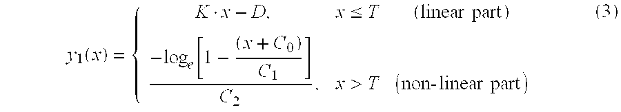
- the non-linearity of measured SIR (in decibels) is very well approximated using an exponential function of the form:
- the non-linear part of the SIR measurement curve is corrected by applying the inverse function (*) of the exponential function defined in equation (2), i.e., - log e ⁇ [ 1 - ( x + C 0 ) C 1 ] C 2 . ( 2 ) *
- the correction function y 1 (x) includes a linear correction part and a non-linear correction part.
- the non-linear part of equation (3) corresponding to the inverse function in equation (2)* is relatively easy to calculate especially since there are only three coefficients C 0 -C 2 to adjust. Therefore, the correction function may be calculated in real time based on currently received SIR values. Alternatively, the correction function can be used to generate a look-up table stored in memory for a desired range of measured SIR values.
- Equation (3) Applying equation (3) to the measured SIR curve illustrated in FIG. 1 results in the corrected SIR curve shown in FIG. 6 .
- the corrected SIR measurement curve is substantially linear over the entire measured SIR value range of ⁇ 5 to 30 dB thereby compensating for the saturation effects experienced over the threshold SIR value T (i.e., 10 dB in this example).
- a second example embodiment of the present invention non-coherently averages detected signal (E b ) values obtained from both the pilot preamble and from each data symbol received during the TPC period.
- T 0 and T 1 are thresholds determined by the noise influence at lower SIR levels; and K 0 , K 1 , D 0 , D 1 , C 0 , C 1 , and C 2 are parameters determined as described below.
- the threshold value(s) T (in the first embodiment) or T 0 , T 1 (in the second embodiment) as well as parameters K, D (in the first embodiment) or K 0 , K 1 , D 0 , D 1 , (in the second embodiment) and C 0 -C 2 depend upon the measured SIR curve.
- the shape of measured SIR curve is a function of the spreading factor and the number of values used for non-coherent averaging. Each parameter value is determined such that it minimizes the maximum absolute error between the ideal and corrected SIR curves. The determination of these values can be done using manual tests and observation or using available numerical optimization algorithms.
- L si is the average self-interference power after de-spreading and RAKE combining.
- L si 0.8
- saturation levels equal to 13 dB, 19 dB, and 22 dB are obtained from the above formula for the spreading factors equal to 16, 64, and 128, respectively.
- These saturation values match the measured values shown in FIGS. 8 a, 1 , and 7 a, respectively.
- the range of linearity of measured SIR curves thus increases proportionally to the spreading factor.
- the following table includes example values of the various coefficients in equation (3) determined for two different spreading factor values 128 and 16.
- the corrected SIR measurement curve obtained by applying Equation (3) to the measured curve shown in FIG. 7 A and using the values in the above table, is shown in FIG. 7 B.
- the curve in FIG. 7B is essentially linear all the way through the SIR range of ⁇ 5 to 30 dB.
- FIGS. 8A and 8B show the measured and corrected SIR curves, respectively, when the spreading factor is reduced from 128 to 16.
- the corrected SIR curve in FIG. 8B is essentially linear.
- FIG. 9 is a flowchart diagram illustrating procedures for implementing a measured SIR correction technique that can be employed in one example implementation of the present invention.
- the first step of the SIR correction routine (block 50 ) is to determine the correction function parameters based on the spreading factor used in the particular CDMA receiver (block 52 ). Based on that spreading factor, specific values for K, D, T, and C 0 -C 2 (for the first example embodiment) or K 0 , K 1 , D 0 , D 1 , T 0 , T 1 , and C 0 -C 2 (for the second example embodiment) are determined and stored in memory. While the remainder of the procedures described below in conjunction with blocks 54 - 62 are repeatedly carried out, the determination of the parameters in block 52 need only be performed once assuming that the spreading factor remains the same.
- the data bit energy E b of the received symbols sampled by the radio receiver is measured over a particular period, e.g., the TPC period (block 54 ).
- the interference power I o is also measured during that same period (block 56 ). That interference power can be measured by simply averaging the power of signals obtained by de-spreading the received signals with an uncorrelated PN code.
- the measured SIR value is then corrected by calculating y 1 (x) or y 2 (x) in accordance with the formulas set forth in equations (3) and (4), respectively, depending upon whether the first or the second example embodiment is employed (block 60 ).
- Power control analysis is then performed based on those corrected SIR values to increase or decrease radio transmit power (block 62 ). For example, if the radio receiver is in a base station, the radio receiver performs the power control analysis and appropriately increases or decreases a mobile station's transmit power.
- the present invention allows accurate SIR measurements for the large range of input values using a simple and flexible analytical (closed form) solution for SIR correction. That solution is readily adaptable to different receiver algorithms for signal energy and interference estimation, and may be efficiently implemented using a suitably programmed digital signal processor or using a table look-up method.
Abstract
Description


| Maximum | ||||||||
| Abs. Error [dB] | ||||||||
| between | ||||||||
| corrected and | ||||||||
| Spread | ideal SIR | |||||||
| Factor | D0 | K0 | D1 | K1 | C0 | C1 | C2 | Values |
| 128 | 11.7 | 2.7 | 2.2 | 1.09 | 14.11 | 38 | 0.10 | 1.65 |
| 16 | 8.71 | 2.08 | 4.51 | 1.49 | 23.41 | 36.95 | 0.21 | 2.38 |

Claims (27)


Priority Applications (11)
| Application Number | Priority Date | Filing Date | Title |
|---|---|---|---|
| US09/038,067 US6292519B1 (en) | 1998-03-11 | 1998-03-11 | Correction of signal-to-interference ratio measurements |
| TW088103311A TW411672B (en) | 1998-03-11 | 1999-03-04 | Correction of signal-to-interference ratio measurements |
| CA002323099A CA2323099C (en) | 1998-03-11 | 1999-03-05 | Correction of signal-interference ratio measurements |
| CN99803795A CN1122377C (en) | 1998-03-11 | 1999-03-05 | Correction of signal-interference ratio measurement |
| JP2000536146A JP4339513B2 (en) | 1998-03-11 | 1999-03-05 | Correction method of signal interference ratio measurement |
| AU29665/99A AU752754B2 (en) | 1998-03-11 | 1999-03-05 | Correction of signal-interference ratio measurements |
| DE69938038T DE69938038D1 (en) | 1998-03-11 | 1999-03-05 | Correction of measurements of the signal-to-interference ratio |
| PCT/SE1999/000338 WO1999046869A1 (en) | 1998-03-11 | 1999-03-05 | Correction of signal-interference ratio measurements |
| KR1020007010101A KR100713118B1 (en) | 1998-03-11 | 1999-03-05 | Correction of signal-interference ratio measurements |
| EP99910904A EP1062742B1 (en) | 1998-03-11 | 1999-03-05 | Correction of signal-interference ratio measures |
| ARP990101047A AR016186A1 (en) | 1998-03-11 | 1999-03-11 | A METHOD FOR PROCESSING A SIGNAL RECEIVED BY CORRECTING A VALUE OF THE SENAL TRANSFER RELATIONSHIP (SIR) OF NON-LINEARITY, A METHOD FOR SIGNAL PROCESSING AS A FUNCTION OF THEIR MEASURED VALUE (SIR) AND A DISPERSED SPECTRUM COMMUNICATION PROVISION TO THE PRACTICE SUCH METHOD |
Applications Claiming Priority (1)
| Application Number | Priority Date | Filing Date | Title |
|---|---|---|---|
| US09/038,067 US6292519B1 (en) | 1998-03-11 | 1998-03-11 | Correction of signal-to-interference ratio measurements |
Publications (1)
| Publication Number | Publication Date |
|---|---|
| US6292519B1 true US6292519B1 (en) | 2001-09-18 |
Family
ID=21897914
Family Applications (1)
| Application Number | Title | Priority Date | Filing Date |
|---|---|---|---|
| US09/038,067 Expired - Lifetime US6292519B1 (en) | 1998-03-11 | 1998-03-11 | Correction of signal-to-interference ratio measurements |
Country Status (11)
| Country | Link |
|---|---|
| US (1) | US6292519B1 (en) |
| EP (1) | EP1062742B1 (en) |
| JP (1) | JP4339513B2 (en) |
| KR (1) | KR100713118B1 (en) |
| CN (1) | CN1122377C (en) |
| AR (1) | AR016186A1 (en) |
| AU (1) | AU752754B2 (en) |
| CA (1) | CA2323099C (en) |
| DE (1) | DE69938038D1 (en) |
| TW (1) | TW411672B (en) |
| WO (1) | WO1999046869A1 (en) |
Cited By (69)
| Publication number | Priority date | Publication date | Assignee | Title |
|---|---|---|---|---|
| US20010008520A1 (en) * | 1999-03-08 | 2001-07-19 | Tiedemann Edward G. | Method and apparatus for maximizing the use of available capacity in a communication system |
| US20010015998A1 (en) * | 1995-06-30 | 2001-08-23 | Gary Lomp | Automatic power control system for a code division multiple access (CDMA) communications system |
| US20020027946A1 (en) * | 1995-06-30 | 2002-03-07 | Ozluturk Fatih M. | Method for adaptive reverse power control for spread-spectrum communications |
| US6404826B1 (en) * | 1998-07-02 | 2002-06-11 | Texas Instruments Incorporated | Iterative signal-to-interference ratio estimation for WCDMA |
| US20020141521A1 (en) * | 2001-02-22 | 2002-10-03 | Alcatel | Receiver for a mobile radio terminal |
| US20020159514A1 (en) * | 2000-01-14 | 2002-10-31 | Kenichi Miyoshi | Sir measuring device and sir measuring method |
| US6493541B1 (en) * | 1999-07-02 | 2002-12-10 | Telefonaktiebolaget Lm Ericsson (Publ) | Transmit power control time delay compensation in a wireless communications system |
| US20030002604A1 (en) * | 2001-06-27 | 2003-01-02 | Koninklijke Philips Electronics N.V. | Frequency offset diversity receiver |
| US6539213B1 (en) * | 1999-06-14 | 2003-03-25 | Time Domain Corporation | System and method for impulse radio power control |
| US20030072392A1 (en) * | 2001-10-16 | 2003-04-17 | Beadle Edward R. | System and method for an in-service decision-directed signal to noise ratio estimator |
| US6668352B1 (en) * | 1999-04-28 | 2003-12-23 | Samsung Electronics Co., Ltd. | Distortion compensating device and method in a multi-code mobile communication system |
| US6678314B2 (en) * | 1999-12-30 | 2004-01-13 | Nokia Corporation | Spreading factor determination |
| US20040008614A1 (en) * | 2002-01-28 | 2004-01-15 | Kabushiki Kaisha Toshiba | Signal selection systems |
| US20040058699A1 (en) * | 2002-09-23 | 2004-03-25 | Elias Jonsson | Methods, systems and computer program products for requesting received power levels based on received block error rates utilizing an anti-windup and/or emergency procedure |
| US20040093178A1 (en) * | 2002-11-08 | 2004-05-13 | Interdigital Technology Corporation | Method and apparatus for determining signal-to-interference ratio with reduced bias effect |
| WO2004051902A1 (en) * | 2002-12-02 | 2004-06-17 | Huawei Technologies Co., Ltd. | Unbiased sir estimation for use in power control methods |
| US6760320B1 (en) * | 1999-04-12 | 2004-07-06 | Alcatel | Channel adaptive fast power control in CDMA |
| US20040171351A1 (en) * | 2003-02-21 | 2004-09-02 | Isao Nakazawa | Interference measurement and evaluation system |
| US20040179484A1 (en) * | 2003-02-21 | 2004-09-16 | Isao Nakazawa | Line quality characteristic evaluation system |
| EP1460789A1 (en) * | 2003-03-21 | 2004-09-22 | Telefonaktiebolaget LM Ericsson (publ) | Method and apparatus for link adaptation |
| WO2004084452A2 (en) * | 2003-03-21 | 2004-09-30 | Telefonaktiebolaget L M Ericsson (Publ) | Method and apparatus for link adaptation |
| US6801516B1 (en) | 1995-06-30 | 2004-10-05 | Interdigital Technology Corporation | Spread-spectrum system for assigning information signals having different data rates |
| US20040202242A1 (en) * | 2002-11-25 | 2004-10-14 | Wei Lin | Method and apparatus for fast convergent power control in a spread spectrum communication system |
| US20040202243A1 (en) * | 2002-11-25 | 2004-10-14 | Wei Lin | Method and apparatus for low power-rise power control using sliding-window-weighted QoS measurements |
| US20040203462A1 (en) * | 2002-11-25 | 2004-10-14 | Wei Lin | Method and apparatus for setting the threshold of a power control target in a spread spectrum communication system |
| US20040209585A1 (en) * | 2003-04-17 | 2004-10-21 | Motorola, Inc. | Method and apparatus for determining an interference level on a fading channel |
| US6816473B2 (en) | 1995-06-30 | 2004-11-09 | Interdigital Technology Corporation | Method for adaptive forward power control for spread-spectrum communications |
| US20040264604A1 (en) * | 2003-06-30 | 2004-12-30 | Alexandre Malette | Unbiased signal to interference ratio in wireless communications devices and methods therefor |
| US20050078740A1 (en) * | 2002-01-07 | 2005-04-14 | Luzhou Xu | Rake receiver with individual finger compensator(s) |
| US6885694B1 (en) | 2000-02-29 | 2005-04-26 | Telefonaktiebolaget Lm Ericsson (Publ) | Correction of received signal and interference estimates |
| US20050094716A1 (en) * | 2002-09-12 | 2005-05-05 | Nokia Corporation | Code phase synchronization |
| US20050135466A1 (en) * | 2003-12-18 | 2005-06-23 | Goel Nagendra K. | Method for accurate estimation of noise for data modems |
| US20050207476A1 (en) * | 2001-11-28 | 2005-09-22 | Nicholas Anderson | Method, arrangement and communication receiver for SNIR estimation |
| US20050220056A1 (en) * | 2004-04-05 | 2005-10-06 | Sony Ericsson Mobile Communications Japan, Inc. | Channel quality estimation method and channel quality estimation apparatus |
| US20050227733A1 (en) * | 2002-02-13 | 2005-10-13 | Pa Consulting Services Limited | Adjustable basedband processing of telecommunications signals |
| US20050281358A1 (en) * | 2004-06-16 | 2005-12-22 | Bottomley Gregory E | SIR estimation in a wireless receiver |
| US20060025082A1 (en) * | 2004-07-29 | 2006-02-02 | Ranganathan Krishnan | System and method for reducing rake finger processing |
| US7058028B1 (en) * | 1999-06-24 | 2006-06-06 | Nokia Networks Oy | Method for controlling the transmission power |
| US20060233222A1 (en) * | 2005-04-14 | 2006-10-19 | Telefonaktiebolaget Lm Ericsson (Publ) | SIR prediction method and apparatus |
| US20060252451A1 (en) * | 2005-05-06 | 2006-11-09 | Cho Sung R | Transmission power control device and method |
| US7236747B1 (en) * | 2003-06-18 | 2007-06-26 | Samsung Electronics Co., Ltd. (SAIT) | Increasing OFDM transmit power via reduction in pilot tone |
| US7263119B1 (en) | 2001-11-29 | 2007-08-28 | Marvell International Ltd. | Decoding method and apparatus |
| CN100336416C (en) * | 2002-07-22 | 2007-09-05 | 中兴通讯股份有限公司 | Method and apparatus for measuring signal interference ratio |
| US20070207741A1 (en) * | 2003-08-07 | 2007-09-06 | Jones Alan E | Method and arrangement for noise variance and sir estimation |
| US7324433B1 (en) | 2001-11-29 | 2008-01-29 | Marvell International Ltd. | Method and apparatus for determining signal quality |
| US20080081624A1 (en) * | 2006-09-29 | 2008-04-03 | Andres Reial | Inter-network handover optimization for terminals using advanced receivers |
| WO2008057018A1 (en) * | 2006-11-07 | 2008-05-15 | Telefonaktiebolaget Lm Ericsson (Publ) | Modified sir values for fast power control |
| US20080151967A1 (en) * | 1999-06-14 | 2008-06-26 | Time Domain Corporation | Time transfer using ultra wideband signals |
| US7415060B1 (en) * | 1999-09-29 | 2008-08-19 | Nokia Corporation | Spread spectrum communication system |
| US7430184B1 (en) * | 1999-12-03 | 2008-09-30 | Ipcom Gmbh & Co. Kg | Method of regulating the transmission power of a master station and a slave station for implementation of the method |
| KR100876812B1 (en) * | 2002-11-05 | 2009-01-07 | 삼성전자주식회사 | Method for adjusting and signalling of desired noise rise over thermal value in using node b controlled scheduling of enhanced uplink dedicated transport channel in wcdma communication system |
| US20090029651A1 (en) * | 2007-06-26 | 2009-01-29 | Telcordia Technologies, Inc. | Method and Procedures for Automatic Calibration of a Wireless Communications System Simulation |
| US20090190485A1 (en) * | 2008-01-30 | 2009-07-30 | Telefonaktiebolaget Lm Ericsson (Publ) | Method of Closed Loop Power Control Adjusted by Self-Interference |
| US7706332B2 (en) | 1995-06-30 | 2010-04-27 | Interdigital Technology Corporation | Method and subscriber unit for performing power control |
| US20100113028A1 (en) * | 2006-10-05 | 2010-05-06 | Arne Simonsson | Method for Predicting Channel Quality Indicator (CQI) Values |
| US20100110991A1 (en) * | 2001-08-24 | 2010-05-06 | Interdigital Technology Corporation | User equipment for physical layer automatic repeat request |
| US7773950B2 (en) | 2004-06-16 | 2010-08-10 | Telefonaktiebolaget Lm Ericsson (Publ) | Benign interference suppression for received signal quality estimation |
| US20100202399A1 (en) * | 2006-02-15 | 2010-08-12 | Severine Catreux-Erceg | Method and apparatus for processing transmit power control (tpc) commands in a wideband cdma (wcdma) network based on a sign metric |
| US7903613B2 (en) | 1995-06-30 | 2011-03-08 | Interdigital Technology Corporation | Code division multiple access (CDMA) communication system |
| US7929498B2 (en) | 1995-06-30 | 2011-04-19 | Interdigital Technology Corporation | Adaptive forward power control and adaptive reverse power control for spread-spectrum communications |
| US20120099634A1 (en) * | 2010-10-25 | 2012-04-26 | Sony Corporation | Receiving device and method, demodulating device and method, and program |
| USRE44010E1 (en) * | 1999-03-17 | 2013-02-19 | Interdigital Technology Corporation | Modular base station with variable communication capacity |
| US20130130738A1 (en) * | 2011-11-18 | 2013-05-23 | Qualcomm Incorporated | Devices and methods for facilitating access probe sequences |
| US20130329590A1 (en) * | 2003-01-14 | 2013-12-12 | Joseph A. Kwak | Received signal to noise indicator |
| US20140128115A1 (en) * | 2012-11-02 | 2014-05-08 | Telefonaktiebolaget L M Ericsson (Publ) | Methods and devices related to effective measurements |
| US20160065328A1 (en) * | 2014-09-02 | 2016-03-03 | MagnaCom Ltd. | Communications in a multi-user environment |
| US9282524B2 (en) | 2006-02-15 | 2016-03-08 | Broadcom Corporation | Method and apparatus for improving noise power estimate in a WCDMA network |
| US20170347289A1 (en) * | 2015-06-27 | 2017-11-30 | Huawei Technologies Co., Ltd. | Method and Apparatus for Determining Signal-to-Noise Ratio in Wireless Communication |
| US10411818B2 (en) | 2015-11-30 | 2019-09-10 | Telecom Italia S.P.A. | Signal to interference and noise ratio estimation |
Families Citing this family (13)
| Publication number | Priority date | Publication date | Assignee | Title |
|---|---|---|---|---|
| JP2885772B1 (en) * | 1997-12-17 | 1999-04-26 | 日本電気移動通信株式会社 | Reception method, reception quality estimation method, transmission power control method, and transmission / reception apparatus in CDMA system |
| US6426971B1 (en) * | 1999-09-13 | 2002-07-30 | Qualcomm Incorporated | System and method for accurately predicting signal to interference and noise ratio to improve communications system performance |
| US6963752B1 (en) | 2000-09-18 | 2005-11-08 | Telefonaktiebolaget L M Ericsson (Publ) | Method and apparatus for setting transmit power control command energy |
| JP3559237B2 (en) * | 2000-11-09 | 2004-08-25 | 松下電器産業株式会社 | Desired wave to interference wave power ratio measurement circuit and desired wave to interference wave power ratio measurement method |
| JP4129747B2 (en) | 2001-10-17 | 2008-08-06 | ソニー株式会社 | Transmitting apparatus, transmission control method, receiving apparatus, and reception control method |
| US6717931B2 (en) * | 2002-01-02 | 2004-04-06 | Nokia Corporation | Adaptive spreading factor based on power control |
| GB2386038A (en) | 2002-02-27 | 2003-09-03 | Motorola Inc | Channel estimation in a radio receiver |
| US7889692B2 (en) * | 2004-09-30 | 2011-02-15 | Alcatel-Lucent Usa, Inc. | Packet error rate estimation in a communication system |
| JP4951274B2 (en) * | 2005-08-19 | 2012-06-13 | 韓國電子通信研究院 | CHANNEL INFORMATION GENERATION APPARATUS AND METHOD, AND APPLICABLE TRANSMISSION APPARATUS AND METHOD THEREOF |
| US7852972B2 (en) * | 2006-05-22 | 2010-12-14 | Qualcomm Incorporated | Single-burst acquistion for wireless communication system |
| US8862175B2 (en) | 2009-12-29 | 2014-10-14 | Telefonaktiebolaget L M Ericsson (Publ) | Correction of estimated SIR used for transmit power control |
| RU2459350C1 (en) * | 2011-07-12 | 2012-08-20 | Государственное образовательное учреждение высшего профессионального образования "Южно-Уральский государственный университет" | Method of filtering and detecting fluctuating radiopulse packet |
| CN105934893B (en) * | 2014-12-30 | 2019-10-01 | 华为技术有限公司 | Method and equipment for transmitting signals |
Citations (11)
| Publication number | Priority date | Publication date | Assignee | Title |
|---|---|---|---|---|
| WO1994005100A1 (en) | 1992-08-21 | 1994-03-03 | Telefonaktiebolaget Lm Ericsson | A method for forming a quality measure for signal bursts |
| US5455967A (en) * | 1993-03-18 | 1995-10-03 | Oki Electric Industry Co., Ltd. | Mobile communication system and transmission power control method for a base station therein |
| US5604766A (en) * | 1994-05-12 | 1997-02-18 | Ntt Mobile Communications Network Inc. | Transmission power control method of a spread-spectrum communication system, and a spread-spectrum communication system employing the control method |
| EP0762668A2 (en) | 1995-08-31 | 1997-03-12 | Nokia Telecommunications Oy | Method for controlling transmission power of a radio transmitter |
| US5623484A (en) | 1993-09-24 | 1997-04-22 | Nokia Telecommunications Oy | Method and apparatus for controlling signal quality in a CDMA cellular telecommunications |
| US5691988A (en) | 1994-11-17 | 1997-11-25 | Hewlett-Packard Company | Method for measuring the sensitivities and interference wave properties fo receivers |
| EP0809365A1 (en) | 1996-05-22 | 1997-11-26 | Ntt Mobile Communications Network Inc. | Scheme for controlling transmission powers during soft handover in a cdma mobile communication system |
| WO1998002981A1 (en) | 1996-07-11 | 1998-01-22 | Telefonaktiebolaget Lm Ericsson (Publ) | Power presetting in a radio communication system |
| EP0833472A1 (en) | 1996-04-12 | 1998-04-01 | Ntt Mobile Communications Network Inc. | Method and instrument for measuring receiving sir and transmission power controller |
| EP0853393A1 (en) | 1996-06-27 | 1998-07-15 | Ntt Mobile Communications Network Inc. | Transmitted power controller |
| US6028894A (en) * | 1996-12-27 | 2000-02-22 | Fujitsu Limited | SIR or SNR measurement apparatus |
Family Cites Families (1)
| Publication number | Priority date | Publication date | Assignee | Title |
|---|---|---|---|---|
| JP3132427B2 (en) * | 1997-07-11 | 2001-02-05 | 日本電気株式会社 | S / N measurement circuit, transmission power control device, and digital communication system |
-
1998
- 1998-03-11 US US09/038,067 patent/US6292519B1/en not_active Expired - Lifetime
-
1999
- 1999-03-04 TW TW088103311A patent/TW411672B/en not_active IP Right Cessation
- 1999-03-05 CA CA002323099A patent/CA2323099C/en not_active Expired - Fee Related
- 1999-03-05 EP EP99910904A patent/EP1062742B1/en not_active Expired - Lifetime
- 1999-03-05 JP JP2000536146A patent/JP4339513B2/en not_active Expired - Fee Related
- 1999-03-05 WO PCT/SE1999/000338 patent/WO1999046869A1/en active IP Right Grant
- 1999-03-05 KR KR1020007010101A patent/KR100713118B1/en not_active IP Right Cessation
- 1999-03-05 DE DE69938038T patent/DE69938038D1/en not_active Expired - Lifetime
- 1999-03-05 AU AU29665/99A patent/AU752754B2/en not_active Ceased
- 1999-03-05 CN CN99803795A patent/CN1122377C/en not_active Expired - Fee Related
- 1999-03-11 AR ARP990101047A patent/AR016186A1/en unknown
Patent Citations (13)
| Publication number | Priority date | Publication date | Assignee | Title |
|---|---|---|---|---|
| WO1994005100A1 (en) | 1992-08-21 | 1994-03-03 | Telefonaktiebolaget Lm Ericsson | A method for forming a quality measure for signal bursts |
| US5455967A (en) * | 1993-03-18 | 1995-10-03 | Oki Electric Industry Co., Ltd. | Mobile communication system and transmission power control method for a base station therein |
| US5623484A (en) | 1993-09-24 | 1997-04-22 | Nokia Telecommunications Oy | Method and apparatus for controlling signal quality in a CDMA cellular telecommunications |
| US5604766A (en) * | 1994-05-12 | 1997-02-18 | Ntt Mobile Communications Network Inc. | Transmission power control method of a spread-spectrum communication system, and a spread-spectrum communication system employing the control method |
| US5691988A (en) | 1994-11-17 | 1997-11-25 | Hewlett-Packard Company | Method for measuring the sensitivities and interference wave properties fo receivers |
| EP0762668A2 (en) | 1995-08-31 | 1997-03-12 | Nokia Telecommunications Oy | Method for controlling transmission power of a radio transmitter |
| EP0833472A1 (en) | 1996-04-12 | 1998-04-01 | Ntt Mobile Communications Network Inc. | Method and instrument for measuring receiving sir and transmission power controller |
| US6034952A (en) * | 1996-04-12 | 2000-03-07 | Ntt Mobile Communications Networks, Inc. | Method and instrument for measuring receiving SIR and transmission power controller |
| EP0809365A1 (en) | 1996-05-22 | 1997-11-26 | Ntt Mobile Communications Network Inc. | Scheme for controlling transmission powers during soft handover in a cdma mobile communication system |
| US5878350A (en) * | 1996-05-22 | 1999-03-02 | Ntt Mobile Communication Network Inc. | Scheme for controlling transmission powers during soft handover in a CDMA mobile communication system |
| EP0853393A1 (en) | 1996-06-27 | 1998-07-15 | Ntt Mobile Communications Network Inc. | Transmitted power controller |
| WO1998002981A1 (en) | 1996-07-11 | 1998-01-22 | Telefonaktiebolaget Lm Ericsson (Publ) | Power presetting in a radio communication system |
| US6028894A (en) * | 1996-12-27 | 2000-02-22 | Fujitsu Limited | SIR or SNR measurement apparatus |
Non-Patent Citations (1)
| Title |
|---|
| Proc. Of VTC'95, Chicago, Illinois, pp. 779-783, Jul. 1995, Koji Ohno, et al., "Wideband coherent DS-CDMA" Coherent Spread Spectrum Systems, J. Holms, Wiley, New York, NY, pp. 363-365, 1982. |
Cited By (134)
| Publication number | Priority date | Publication date | Assignee | Title |
|---|---|---|---|---|
| US7756190B2 (en) | 1995-06-30 | 2010-07-13 | Interdigital Technology Corporation | Transferring voice and non-voice data |
| US8737363B2 (en) | 1995-06-30 | 2014-05-27 | Interdigital Technology Corporation | Code division multiple access (CDMA) communication system |
| US7903613B2 (en) | 1995-06-30 | 2011-03-08 | Interdigital Technology Corporation | Code division multiple access (CDMA) communication system |
| US6985467B2 (en) | 1995-06-30 | 2006-01-10 | Interdigital Technology Corporation | Rapid acquisition spreading codes for spread-spectrum communications |
| US6744809B2 (en) | 1995-06-30 | 2004-06-01 | Interdigital Technology Corporation | Efficient multipath centroid tracking circuit for a code division multiple access (CDMA) system |
| US6873645B2 (en) * | 1995-06-30 | 2005-03-29 | Interdigital Technology Corporation | Automatic power control system for a code division multiple access (CDMA) communications system |
| US20010015998A1 (en) * | 1995-06-30 | 2001-08-23 | Gary Lomp | Automatic power control system for a code division multiple access (CDMA) communications system |
| US6831905B1 (en) | 1995-06-30 | 2004-12-14 | Interdigital Technology Corporation | Spread spectrum system assigning information signals to message-code signals |
| US9564963B2 (en) | 1995-06-30 | 2017-02-07 | Interdigital Technology Corporation | Automatic power control system for a code division multiple access (CDMA) communications system |
| US6816473B2 (en) | 1995-06-30 | 2004-11-09 | Interdigital Technology Corporation | Method for adaptive forward power control for spread-spectrum communications |
| US6788662B2 (en) | 1995-06-30 | 2004-09-07 | Interdigital Technology Corporation | Method for adaptive reverse power control for spread-spectrum communications |
| US20020027946A1 (en) * | 1995-06-30 | 2002-03-07 | Ozluturk Fatih M. | Method for adaptive reverse power control for spread-spectrum communications |
| US7706332B2 (en) | 1995-06-30 | 2010-04-27 | Interdigital Technology Corporation | Method and subscriber unit for performing power control |
| US7929498B2 (en) | 1995-06-30 | 2011-04-19 | Interdigital Technology Corporation | Adaptive forward power control and adaptive reverse power control for spread-spectrum communications |
| US6801516B1 (en) | 1995-06-30 | 2004-10-05 | Interdigital Technology Corporation | Spread-spectrum system for assigning information signals having different data rates |
| US6404826B1 (en) * | 1998-07-02 | 2002-06-11 | Texas Instruments Incorporated | Iterative signal-to-interference ratio estimation for WCDMA |
| US7720022B2 (en) * | 1999-03-08 | 2010-05-18 | Qualcomm Incorporated | Method and apparatus for maximizing the use of available capacity in a communication system |
| US20010008520A1 (en) * | 1999-03-08 | 2001-07-19 | Tiedemann Edward G. | Method and apparatus for maximizing the use of available capacity in a communication system |
| US8379605B2 (en) | 1999-03-08 | 2013-02-19 | Qualcomm Incorporated | Method and apparatus for maximizing the use of available capacity in a communication system |
| USRE44010E1 (en) * | 1999-03-17 | 2013-02-19 | Interdigital Technology Corporation | Modular base station with variable communication capacity |
| US6760320B1 (en) * | 1999-04-12 | 2004-07-06 | Alcatel | Channel adaptive fast power control in CDMA |
| US6668352B1 (en) * | 1999-04-28 | 2003-12-23 | Samsung Electronics Co., Ltd. | Distortion compensating device and method in a multi-code mobile communication system |
| US6539213B1 (en) * | 1999-06-14 | 2003-03-25 | Time Domain Corporation | System and method for impulse radio power control |
| US7209724B2 (en) | 1999-06-14 | 2007-04-24 | Alereon, Inc. | Method and apparatus for power control in an ultra wideband radio system |
| US20030194979A1 (en) * | 1999-06-14 | 2003-10-16 | Richards James L. | Method and apparatus for power control in an ultra wideband impulse radio system |
| US7873099B2 (en) | 1999-06-14 | 2011-01-18 | Time Domain Corporation | Time transfer using ultra wideband signals |
| US6571089B1 (en) * | 1999-06-14 | 2003-05-27 | Time Domain Corporation | Method and apparatus for moderating interference while effecting impulse radio wireless control of equipment |
| US20080151967A1 (en) * | 1999-06-14 | 2008-06-26 | Time Domain Corporation | Time transfer using ultra wideband signals |
| US7079827B2 (en) * | 1999-06-14 | 2006-07-18 | Alereon, Inc. | Method and apparatus for power control in an ultra wideband impulse radio system |
| US7577415B1 (en) | 1999-06-14 | 2009-08-18 | Alereon, Inc. | Method and apparatus for ultra wideband power control |
| US20060178163A1 (en) * | 1999-06-14 | 2006-08-10 | Richards James L | Method and apparatus for power control in an ultra wideband radio system |
| US7058028B1 (en) * | 1999-06-24 | 2006-06-06 | Nokia Networks Oy | Method for controlling the transmission power |
| US6493541B1 (en) * | 1999-07-02 | 2002-12-10 | Telefonaktiebolaget Lm Ericsson (Publ) | Transmit power control time delay compensation in a wireless communications system |
| US7415060B1 (en) * | 1999-09-29 | 2008-08-19 | Nokia Corporation | Spread spectrum communication system |
| US7430184B1 (en) * | 1999-12-03 | 2008-09-30 | Ipcom Gmbh & Co. Kg | Method of regulating the transmission power of a master station and a slave station for implementation of the method |
| US6678314B2 (en) * | 1999-12-30 | 2004-01-13 | Nokia Corporation | Spreading factor determination |
| US20020159514A1 (en) * | 2000-01-14 | 2002-10-31 | Kenichi Miyoshi | Sir measuring device and sir measuring method |
| US6885694B1 (en) | 2000-02-29 | 2005-04-26 | Telefonaktiebolaget Lm Ericsson (Publ) | Correction of received signal and interference estimates |
| US20020141521A1 (en) * | 2001-02-22 | 2002-10-03 | Alcatel | Receiver for a mobile radio terminal |
| US7099418B2 (en) * | 2001-02-22 | 2006-08-29 | Tcl Communications Technology Holdings Limited | Receiver for a mobile radio terminal |
| US20030002604A1 (en) * | 2001-06-27 | 2003-01-02 | Koninklijke Philips Electronics N.V. | Frequency offset diversity receiver |
| US8102801B2 (en) | 2001-08-24 | 2012-01-24 | Interdigital Technology Corporation | User equipment for physical layer automatic repeat request |
| US20100110991A1 (en) * | 2001-08-24 | 2010-05-06 | Interdigital Technology Corporation | User equipment for physical layer automatic repeat request |
| US7076001B2 (en) * | 2001-10-16 | 2006-07-11 | Harris Corporation | System and method for an in-service decision-directed signal to noise ratio estimator |
| US20030072392A1 (en) * | 2001-10-16 | 2003-04-17 | Beadle Edward R. | System and method for an in-service decision-directed signal to noise ratio estimator |
| US7324783B2 (en) * | 2001-11-28 | 2008-01-29 | Ipwireless, Inc. | Method, arrangement and communication receiver for SNIR estimation |
| US20050207476A1 (en) * | 2001-11-28 | 2005-09-22 | Nicholas Anderson | Method, arrangement and communication receiver for SNIR estimation |
| US7606296B1 (en) | 2001-11-29 | 2009-10-20 | Marvell International Ltd. | Decoding method and apparatus |
| US8059707B1 (en) | 2001-11-29 | 2011-11-15 | Marvell International Ltd. | Decoding method and apparatus |
| US7746925B1 (en) | 2001-11-29 | 2010-06-29 | Marvell International Ltd. | Decoding method and apparatus |
| US7701871B1 (en) | 2001-11-29 | 2010-04-20 | Marvell International Ltd. | Method and apparatus for determining signal quality |
| US7324433B1 (en) | 2001-11-29 | 2008-01-29 | Marvell International Ltd. | Method and apparatus for determining signal quality |
| US7263119B1 (en) | 2001-11-29 | 2007-08-28 | Marvell International Ltd. | Decoding method and apparatus |
| US7974331B2 (en) * | 2002-01-07 | 2011-07-05 | St-Ericsson Sa | Rake receiver with individual finger compensator(s) |
| US20050078740A1 (en) * | 2002-01-07 | 2005-04-14 | Luzhou Xu | Rake receiver with individual finger compensator(s) |
| US20040008614A1 (en) * | 2002-01-28 | 2004-01-15 | Kabushiki Kaisha Toshiba | Signal selection systems |
| US7426232B2 (en) * | 2002-01-28 | 2008-09-16 | Kabushiki Kaisha Toshiba | Signal selection systems |
| US20050227733A1 (en) * | 2002-02-13 | 2005-10-13 | Pa Consulting Services Limited | Adjustable basedband processing of telecommunications signals |
| CN100336416C (en) * | 2002-07-22 | 2007-09-05 | 中兴通讯股份有限公司 | Method and apparatus for measuring signal interference ratio |
| US20050094716A1 (en) * | 2002-09-12 | 2005-05-05 | Nokia Corporation | Code phase synchronization |
| US7352834B2 (en) * | 2002-09-12 | 2008-04-01 | Nokia Corporation | Code phase synchronization |
| US20040058699A1 (en) * | 2002-09-23 | 2004-03-25 | Elias Jonsson | Methods, systems and computer program products for requesting received power levels based on received block error rates utilizing an anti-windup and/or emergency procedure |
| US7162262B2 (en) | 2002-09-23 | 2007-01-09 | Telefonaktiebolaget Lm Ericsson (Publ) | Methods, systems and computer program products for requesting received power levels based on received block error rates utilizing an anti-windup and/or emergency procedure |
| KR100876812B1 (en) * | 2002-11-05 | 2009-01-07 | 삼성전자주식회사 | Method for adjusting and signalling of desired noise rise over thermal value in using node b controlled scheduling of enhanced uplink dedicated transport channel in wcdma communication system |
| US7069190B2 (en) | 2002-11-08 | 2006-06-27 | Interdigital Technology Corporation | Estimator for determining signal-to-interference ratio with reduced bias effect |
| US7254496B2 (en) | 2002-11-08 | 2007-08-07 | Interdigital Technology Corporation | Estimator for determining signal-to-interference ratio with reduced bias effect |
| US6957175B2 (en) * | 2002-11-08 | 2005-10-18 | Interdigital Technology Corporation | Method and apparatus for determining signal-to-interference ratio with reduced bias effect |
| US20040093178A1 (en) * | 2002-11-08 | 2004-05-13 | Interdigital Technology Corporation | Method and apparatus for determining signal-to-interference ratio with reduced bias effect |
| US20050187728A1 (en) * | 2002-11-08 | 2005-08-25 | Interdigital Technology Corporation | Estimator for determining signal-to-interference ratio with reduced bias effect |
| US20060206290A1 (en) * | 2002-11-08 | 2006-09-14 | Interdigital Technology Corporation | Estimator for determining signal-to-interference ratio with reduced bias effect |
| WO2004045085A3 (en) * | 2002-11-08 | 2005-03-10 | Interdigital Tech Corp | Method and apparatus for determining signal-to-interference ratio with reduced bias effect |
| US20040203462A1 (en) * | 2002-11-25 | 2004-10-14 | Wei Lin | Method and apparatus for setting the threshold of a power control target in a spread spectrum communication system |
| US20040202243A1 (en) * | 2002-11-25 | 2004-10-14 | Wei Lin | Method and apparatus for low power-rise power control using sliding-window-weighted QoS measurements |
| US20040202242A1 (en) * | 2002-11-25 | 2004-10-14 | Wei Lin | Method and apparatus for fast convergent power control in a spread spectrum communication system |
| US7330504B2 (en) | 2002-11-25 | 2008-02-12 | Texas Instruments Incorporated | Method and apparatus for low power-rise power control using sliding-window-weighted QoS measurements |
| US7339994B2 (en) | 2002-11-25 | 2008-03-04 | Texas Instruments Incorporated | Method and apparatus for fast convergent power control in a spread spectrum communication system |
| WO2004051902A1 (en) * | 2002-12-02 | 2004-06-17 | Huawei Technologies Co., Ltd. | Unbiased sir estimation for use in power control methods |
| US9014650B2 (en) * | 2003-01-14 | 2015-04-21 | Intel Corporation | Received signal to noise indicator |
| US20130329590A1 (en) * | 2003-01-14 | 2013-12-12 | Joseph A. Kwak | Received signal to noise indicator |
| US7107011B2 (en) * | 2003-02-21 | 2006-09-12 | Fujitsu Limited | Interference measurement and evaluation system |
| US20040171351A1 (en) * | 2003-02-21 | 2004-09-02 | Isao Nakazawa | Interference measurement and evaluation system |
| US7177599B2 (en) * | 2003-02-21 | 2007-02-13 | Fujitsu Limited | Line quality characteristic evaluation system |
| US20040179484A1 (en) * | 2003-02-21 | 2004-09-16 | Isao Nakazawa | Line quality characteristic evaluation system |
| EP1460789A1 (en) * | 2003-03-21 | 2004-09-22 | Telefonaktiebolaget LM Ericsson (publ) | Method and apparatus for link adaptation |
| WO2004084452A2 (en) * | 2003-03-21 | 2004-09-30 | Telefonaktiebolaget L M Ericsson (Publ) | Method and apparatus for link adaptation |
| WO2004084452A3 (en) * | 2003-03-21 | 2008-01-17 | Ericsson Telefon Ab L M | Method and apparatus for link adaptation |
| US20070026803A1 (en) * | 2003-03-21 | 2007-02-01 | Peter Malm | Method and apparatus for link adaptation |
| US20040209585A1 (en) * | 2003-04-17 | 2004-10-21 | Motorola, Inc. | Method and apparatus for determining an interference level on a fading channel |
| US20070213014A1 (en) * | 2003-06-18 | 2007-09-13 | Dan Meacham | Increasing OFDM transmit power via reduction in pilot tone |
| US7236747B1 (en) * | 2003-06-18 | 2007-06-26 | Samsung Electronics Co., Ltd. (SAIT) | Increasing OFDM transmit power via reduction in pilot tone |
| US7809397B2 (en) * | 2003-06-18 | 2010-10-05 | Staccato Communications, Inc. | Increasing OFDM transmit power via reduction in pilot tone |
| US7200190B2 (en) * | 2003-06-30 | 2007-04-03 | Motorola, Inc. | Unbiased signal to interference ratio in wireless communications devices and methods therefor |
| CN1849793B (en) * | 2003-06-30 | 2010-12-22 | 摩托罗拉公司 | Unbiased signal to interference ratio in wireless communications devices and methods therefor |
| US20040264604A1 (en) * | 2003-06-30 | 2004-12-30 | Alexandre Malette | Unbiased signal to interference ratio in wireless communications devices and methods therefor |
| WO2005006779A3 (en) * | 2003-06-30 | 2006-02-09 | Motorola Inc | Unbiased signal to interference ratio in wireless communications devices and methods therefor |
| US7590388B2 (en) * | 2003-08-07 | 2009-09-15 | Ipwireless, Inc. | Method and arrangement for noise variance and SIR estimation |
| US20070207741A1 (en) * | 2003-08-07 | 2007-09-06 | Jones Alan E | Method and arrangement for noise variance and sir estimation |
| US7362801B2 (en) * | 2003-12-18 | 2008-04-22 | Lsi Logic Corporation | Method for accurate estimation of noise for data modems |
| US20050135466A1 (en) * | 2003-12-18 | 2005-06-23 | Goel Nagendra K. | Method for accurate estimation of noise for data modems |
| US7474628B2 (en) * | 2004-04-05 | 2009-01-06 | Sony Ericsson Mobile Communications Japan, Inc. | Channel quality estimation method and channel quality estimation apparatus |
| US20050220056A1 (en) * | 2004-04-05 | 2005-10-06 | Sony Ericsson Mobile Communications Japan, Inc. | Channel quality estimation method and channel quality estimation apparatus |
| US7773950B2 (en) | 2004-06-16 | 2010-08-10 | Telefonaktiebolaget Lm Ericsson (Publ) | Benign interference suppression for received signal quality estimation |
| US8599972B2 (en) | 2004-06-16 | 2013-12-03 | Telefonaktiebolaget L M Ericsson (Publ) | SIR estimation in a wireless receiver |
| US20050281358A1 (en) * | 2004-06-16 | 2005-12-22 | Bottomley Gregory E | SIR estimation in a wireless receiver |
| US20080020713A1 (en) * | 2004-07-29 | 2008-01-24 | Qualcomm Incorporated | System and method for reducing rake finger processing |
| US7292826B2 (en) * | 2004-07-29 | 2007-11-06 | Qualcomm Incorporated | System and method for reducing rake finger processing |
| US7447481B2 (en) | 2004-07-29 | 2008-11-04 | Qualcomm Incorporated | System and method for reducing rake finger processing |
| US20060025082A1 (en) * | 2004-07-29 | 2006-02-02 | Ranganathan Krishnan | System and method for reducing rake finger processing |
| US20060233222A1 (en) * | 2005-04-14 | 2006-10-19 | Telefonaktiebolaget Lm Ericsson (Publ) | SIR prediction method and apparatus |
| US7711033B2 (en) | 2005-04-14 | 2010-05-04 | Telefonaktiebolaget Lm Ericsson (Publ) | SIR prediction method and apparatus |
| US20060252451A1 (en) * | 2005-05-06 | 2006-11-09 | Cho Sung R | Transmission power control device and method |
| US8068869B2 (en) * | 2006-02-15 | 2011-11-29 | Broadcom Corporation | Method and apparatus for processing transmit power control (TPC) commands in a wideband CDMA (WCDMA) network based on a sign metric |
| US20100202399A1 (en) * | 2006-02-15 | 2010-08-12 | Severine Catreux-Erceg | Method and apparatus for processing transmit power control (tpc) commands in a wideband cdma (wcdma) network based on a sign metric |
| US9282524B2 (en) | 2006-02-15 | 2016-03-08 | Broadcom Corporation | Method and apparatus for improving noise power estimate in a WCDMA network |
| US20080081624A1 (en) * | 2006-09-29 | 2008-04-03 | Andres Reial | Inter-network handover optimization for terminals using advanced receivers |
| US20100113028A1 (en) * | 2006-10-05 | 2010-05-06 | Arne Simonsson | Method for Predicting Channel Quality Indicator (CQI) Values |
| US8688049B2 (en) * | 2006-10-05 | 2014-04-01 | Telefonaktiebolaget L M Ericsson (Publ) | Method for predicting channel quality indicator (CQI) values |
| WO2008057018A1 (en) * | 2006-11-07 | 2008-05-15 | Telefonaktiebolaget Lm Ericsson (Publ) | Modified sir values for fast power control |
| US9226249B2 (en) | 2006-11-07 | 2015-12-29 | Telefonaktiebolaget L M Ericsson (Publ) | Modified SIR values for fast power control |
| US8554234B2 (en) * | 2007-06-26 | 2013-10-08 | Telcordia Technologies, Inc. | Method and procedures for automatic calibration of a wireless communications system simulation |
| US20090029651A1 (en) * | 2007-06-26 | 2009-01-29 | Telcordia Technologies, Inc. | Method and Procedures for Automatic Calibration of a Wireless Communications System Simulation |
| US20090190485A1 (en) * | 2008-01-30 | 2009-07-30 | Telefonaktiebolaget Lm Ericsson (Publ) | Method of Closed Loop Power Control Adjusted by Self-Interference |
| US8576902B2 (en) * | 2010-10-25 | 2013-11-05 | Sony Corporation | Receiving device and method, demodulating device and method, and program |
| US20120099634A1 (en) * | 2010-10-25 | 2012-04-26 | Sony Corporation | Receiving device and method, demodulating device and method, and program |
| US9241298B2 (en) * | 2011-11-18 | 2016-01-19 | Qualcomm Incorporated | Devices and methods for facilitating access probe sequences |
| US20130130738A1 (en) * | 2011-11-18 | 2013-05-23 | Qualcomm Incorporated | Devices and methods for facilitating access probe sequences |
| US9615316B2 (en) | 2011-11-18 | 2017-04-04 | Qualcomm Incorporated | Methods and devices for facilitating modified cell reselection parameters and procedures when access terminals exhibit little or no mobility |
| US20140128115A1 (en) * | 2012-11-02 | 2014-05-08 | Telefonaktiebolaget L M Ericsson (Publ) | Methods and devices related to effective measurements |
| US9503216B2 (en) * | 2012-11-02 | 2016-11-22 | Telefonaktiebolaget L M Ericsson (Publ) | Methods and devices related to effective measurements |
| RU2621678C2 (en) * | 2012-11-02 | 2017-06-07 | Телефонактиеболагет Л М Эрикссон (Пабл) | Method and device relating to effective measurements with reduced interference |
| US20160065328A1 (en) * | 2014-09-02 | 2016-03-03 | MagnaCom Ltd. | Communications in a multi-user environment |
| US20170347289A1 (en) * | 2015-06-27 | 2017-11-30 | Huawei Technologies Co., Ltd. | Method and Apparatus for Determining Signal-to-Noise Ratio in Wireless Communication |
| US10477431B2 (en) * | 2015-06-27 | 2019-11-12 | Huawei Technologies Co., Ltd. | Method and apparatus for determining signal-to-noise ratio in wireless communication |
| US10411818B2 (en) | 2015-11-30 | 2019-09-10 | Telecom Italia S.P.A. | Signal to interference and noise ratio estimation |
Also Published As
| Publication number | Publication date |
|---|---|
| JP2002507077A (en) | 2002-03-05 |
| AU2966599A (en) | 1999-09-27 |
| EP1062742A1 (en) | 2000-12-27 |
| AR016186A1 (en) | 2001-06-20 |
| CA2323099A1 (en) | 1999-09-16 |
| CA2323099C (en) | 2007-06-12 |
| CN1122377C (en) | 2003-09-24 |
| EP1062742B1 (en) | 2008-01-23 |
| DE69938038D1 (en) | 2008-03-13 |
| JP4339513B2 (en) | 2009-10-07 |
| KR20010041818A (en) | 2001-05-25 |
| AU752754B2 (en) | 2002-09-26 |
| KR100713118B1 (en) | 2007-05-02 |
| TW411672B (en) | 2000-11-11 |
| CN1292953A (en) | 2001-04-25 |
| WO1999046869A1 (en) | 1999-09-16 |
Similar Documents
| Publication | Publication Date | Title |
|---|---|---|
| US6292519B1 (en) | Correction of signal-to-interference ratio measurements | |
| US6414948B1 (en) | Electric power controlling system for variable bit rate CDMA transmission and mobile telephone system | |
| US5799005A (en) | System and method for determining received pilot power and path loss in a CDMA communication system | |
| EP1064732B1 (en) | Method and system for providing an estimate of the signal strength of a received signal | |
| EP1163738B1 (en) | Weighted open loop power control in a time division duplex communication system | |
| KR100233981B1 (en) | Transmitting power control method and device thereof | |
| KR100725429B1 (en) | Method and apparatus for determining the closed loop power control set point in a wireless packet data communication system | |
| KR100616756B1 (en) | Apparatus and method for controlling the transmission power of the forward link of a wireless communication system | |
| US6885694B1 (en) | Correction of received signal and interference estimates | |
| KR20000013025A (en) | Forward initial transmitting power control device of telecommunication system and method therefor | |
| WO2009142572A1 (en) | Systems and methods for sir estimation for power control | |
| JP4681180B2 (en) | CDMA signal component processing method | |
| US20020183086A1 (en) | Technique for improving open loop power control in spread spectrum telecommunications systems | |
| JP3519338B2 (en) | Receiver and gain control method | |
| EP1024606A2 (en) | Open loop power control for wireless mobile stations | |
| US7421010B2 (en) | Mobile communication terminal | |
| EP1156600A1 (en) | Cdma terminal and cdma method | |
| EP1065802B1 (en) | Transmission power control method and apparatus by measuring the Eb/No of a weighted signals' combination | |
| EP1146668A1 (en) | Communication terminal, base station system, and method of controlling transmission power | |
| KR20010028190A (en) | Apparatus and method for estimating channel using pilot and traffic channel and DS/CDMA receiver comprising it |
Legal Events
| Date | Code | Title | Description |
|---|---|---|---|
| AS | Assignment |
Owner name: TELEFONAKTIEBOLAGET LM ERICSSON, SWEDEN Free format text: ASSIGNMENT OF ASSIGNORS INTEREST;ASSIGNOR:POPOVIC', BRANISLAV M.;REEL/FRAME:009076/0923 Effective date: 19980302 |
|
| STCF | Information on status: patent grant |
Free format text: PATENTED CASE |
|
| FPAY | Fee payment |
Year of fee payment: 4 |
|
| FPAY | Fee payment |
Year of fee payment: 8 |
|
| FPAY | Fee payment |
Year of fee payment: 12 |
|
| AS | Assignment |
Owner name: CLUSTER LLC, DELAWARE Free format text: ASSIGNMENT OF ASSIGNORS INTEREST;ASSIGNOR:TELEFONAKTIEBOLAGET L M ERICSSON (PUBL);REEL/FRAME:030201/0186 Effective date: 20130211 |
|
| AS | Assignment |
Owner name: UNWIRED PLANET, LLC, NEVADA Free format text: ASSIGNMENT OF ASSIGNORS INTEREST;ASSIGNOR:CLUSTER LLC;REEL/FRAME:030219/0001 Effective date: 20130213 |
|
| AS | Assignment |
Owner name: CLUSTER LLC, SWEDEN Free format text: NOTICE OF GRANT OF SECURITY INTEREST IN PATENTS;ASSIGNOR:UNWIRED PLANET, LLC;REEL/FRAME:030369/0601 Effective date: 20130213 |