US6284347B1 - Cellular panel and method and apparatus for making the same - Google Patents
Cellular panel and method and apparatus for making the same Download PDFInfo
- Publication number
- US6284347B1 US6284347B1 US09/442,090 US44209099A US6284347B1 US 6284347 B1 US6284347 B1 US 6284347B1 US 44209099 A US44209099 A US 44209099A US 6284347 B1 US6284347 B1 US 6284347B1
- Authority
- US
- United States
- Prior art keywords
- panel
- sheet
- cell
- web
- sheets
- Prior art date
- Legal status (The legal status is an assumption and is not a legal conclusion. Google has not performed a legal analysis and makes no representation as to the accuracy of the status listed.)
- Expired - Lifetime
Links
Images


Classifications
-
- B—PERFORMING OPERATIONS; TRANSPORTING
- B29—WORKING OF PLASTICS; WORKING OF SUBSTANCES IN A PLASTIC STATE IN GENERAL
- B29C—SHAPING OR JOINING OF PLASTICS; SHAPING OF MATERIAL IN A PLASTIC STATE, NOT OTHERWISE PROVIDED FOR; AFTER-TREATMENT OF THE SHAPED PRODUCTS, e.g. REPAIRING
- B29C66/00—General aspects of processes or apparatus for joining preformed parts
- B29C66/01—General aspects dealing with the joint area or with the area to be joined
- B29C66/03—After-treatments in the joint area
- B29C66/032—Mechanical after-treatments
- B29C66/0324—Reforming or reshaping the joint, e.g. folding over
- B29C66/03241—Flattening
- B29C66/03242—Flattening of sheets being positioned in abutment, e.g. after folding open of an overlap joint
-
- B—PERFORMING OPERATIONS; TRANSPORTING
- B29—WORKING OF PLASTICS; WORKING OF SUBSTANCES IN A PLASTIC STATE IN GENERAL
- B29C—SHAPING OR JOINING OF PLASTICS; SHAPING OF MATERIAL IN A PLASTIC STATE, NOT OTHERWISE PROVIDED FOR; AFTER-TREATMENT OF THE SHAPED PRODUCTS, e.g. REPAIRING
- B29C65/00—Joining or sealing of preformed parts, e.g. welding of plastics materials; Apparatus therefor
- B29C65/02—Joining or sealing of preformed parts, e.g. welding of plastics materials; Apparatus therefor by heating, with or without pressure
- B29C65/08—Joining or sealing of preformed parts, e.g. welding of plastics materials; Apparatus therefor by heating, with or without pressure using ultrasonic vibrations
- B29C65/083—Joining or sealing of preformed parts, e.g. welding of plastics materials; Apparatus therefor by heating, with or without pressure using ultrasonic vibrations using a rotary sonotrode or a rotary anvil
- B29C65/086—Joining or sealing of preformed parts, e.g. welding of plastics materials; Apparatus therefor by heating, with or without pressure using ultrasonic vibrations using a rotary sonotrode or a rotary anvil using a rotary anvil
-
- B—PERFORMING OPERATIONS; TRANSPORTING
- B29—WORKING OF PLASTICS; WORKING OF SUBSTANCES IN A PLASTIC STATE IN GENERAL
- B29C—SHAPING OR JOINING OF PLASTICS; SHAPING OF MATERIAL IN A PLASTIC STATE, NOT OTHERWISE PROVIDED FOR; AFTER-TREATMENT OF THE SHAPED PRODUCTS, e.g. REPAIRING
- B29C65/00—Joining or sealing of preformed parts, e.g. welding of plastics materials; Apparatus therefor
- B29C65/48—Joining or sealing of preformed parts, e.g. welding of plastics materials; Apparatus therefor using adhesives, i.e. using supplementary joining material; solvent bonding
-
- B—PERFORMING OPERATIONS; TRANSPORTING
- B29—WORKING OF PLASTICS; WORKING OF SUBSTANCES IN A PLASTIC STATE IN GENERAL
- B29C—SHAPING OR JOINING OF PLASTICS; SHAPING OF MATERIAL IN A PLASTIC STATE, NOT OTHERWISE PROVIDED FOR; AFTER-TREATMENT OF THE SHAPED PRODUCTS, e.g. REPAIRING
- B29C65/00—Joining or sealing of preformed parts, e.g. welding of plastics materials; Apparatus therefor
- B29C65/74—Joining or sealing of preformed parts, e.g. welding of plastics materials; Apparatus therefor by welding and severing, or by joining and severing, the severing being performed in the area to be joined, next to the area to be joined, in the joint area or next to the joint area
- B29C65/743—Joining or sealing of preformed parts, e.g. welding of plastics materials; Apparatus therefor by welding and severing, or by joining and severing, the severing being performed in the area to be joined, next to the area to be joined, in the joint area or next to the joint area using the same tool for both joining and severing, said tool being monobloc or formed by several parts mounted together and forming a monobloc
- B29C65/7443—Joining or sealing of preformed parts, e.g. welding of plastics materials; Apparatus therefor by welding and severing, or by joining and severing, the severing being performed in the area to be joined, next to the area to be joined, in the joint area or next to the joint area using the same tool for both joining and severing, said tool being monobloc or formed by several parts mounted together and forming a monobloc by means of ultrasonic vibrations
-
- B—PERFORMING OPERATIONS; TRANSPORTING
- B29—WORKING OF PLASTICS; WORKING OF SUBSTANCES IN A PLASTIC STATE IN GENERAL
- B29C—SHAPING OR JOINING OF PLASTICS; SHAPING OF MATERIAL IN A PLASTIC STATE, NOT OTHERWISE PROVIDED FOR; AFTER-TREATMENT OF THE SHAPED PRODUCTS, e.g. REPAIRING
- B29C65/00—Joining or sealing of preformed parts, e.g. welding of plastics materials; Apparatus therefor
- B29C65/74—Joining or sealing of preformed parts, e.g. welding of plastics materials; Apparatus therefor by welding and severing, or by joining and severing, the severing being performed in the area to be joined, next to the area to be joined, in the joint area or next to the joint area
- B29C65/749—Removing scrap
-
- B—PERFORMING OPERATIONS; TRANSPORTING
- B29—WORKING OF PLASTICS; WORKING OF SUBSTANCES IN A PLASTIC STATE IN GENERAL
- B29C—SHAPING OR JOINING OF PLASTICS; SHAPING OF MATERIAL IN A PLASTIC STATE, NOT OTHERWISE PROVIDED FOR; AFTER-TREATMENT OF THE SHAPED PRODUCTS, e.g. REPAIRING
- B29C65/00—Joining or sealing of preformed parts, e.g. welding of plastics materials; Apparatus therefor
- B29C65/78—Means for handling the parts to be joined, e.g. for making containers or hollow articles, e.g. means for handling sheets, plates, web-like materials, tubular articles, hollow articles or elements to be joined therewith; Means for discharging the joined articles from the joining apparatus
- B29C65/7841—Holding or clamping means for handling purposes
- B29C65/7847—Holding or clamping means for handling purposes using vacuum to hold at least one of the parts to be joined
-
- B—PERFORMING OPERATIONS; TRANSPORTING
- B29—WORKING OF PLASTICS; WORKING OF SUBSTANCES IN A PLASTIC STATE IN GENERAL
- B29C—SHAPING OR JOINING OF PLASTICS; SHAPING OF MATERIAL IN A PLASTIC STATE, NOT OTHERWISE PROVIDED FOR; AFTER-TREATMENT OF THE SHAPED PRODUCTS, e.g. REPAIRING
- B29C65/00—Joining or sealing of preformed parts, e.g. welding of plastics materials; Apparatus therefor
- B29C65/78—Means for handling the parts to be joined, e.g. for making containers or hollow articles, e.g. means for handling sheets, plates, web-like materials, tubular articles, hollow articles or elements to be joined therewith; Means for discharging the joined articles from the joining apparatus
- B29C65/7858—Means for handling the parts to be joined, e.g. for making containers or hollow articles, e.g. means for handling sheets, plates, web-like materials, tubular articles, hollow articles or elements to be joined therewith; Means for discharging the joined articles from the joining apparatus characterised by the feeding movement of the parts to be joined
- B29C65/7888—Means for handling of moving sheets or webs
- B29C65/7894—Means for handling of moving sheets or webs of continuously moving sheets or webs
-
- B—PERFORMING OPERATIONS; TRANSPORTING
- B29—WORKING OF PLASTICS; WORKING OF SUBSTANCES IN A PLASTIC STATE IN GENERAL
- B29C—SHAPING OR JOINING OF PLASTICS; SHAPING OF MATERIAL IN A PLASTIC STATE, NOT OTHERWISE PROVIDED FOR; AFTER-TREATMENT OF THE SHAPED PRODUCTS, e.g. REPAIRING
- B29C66/00—General aspects of processes or apparatus for joining preformed parts
- B29C66/01—General aspects dealing with the joint area or with the area to be joined
- B29C66/03—After-treatments in the joint area
- B29C66/032—Mechanical after-treatments
- B29C66/0324—Reforming or reshaping the joint, e.g. folding over
- B29C66/03241—Flattening
-
- B—PERFORMING OPERATIONS; TRANSPORTING
- B29—WORKING OF PLASTICS; WORKING OF SUBSTANCES IN A PLASTIC STATE IN GENERAL
- B29C—SHAPING OR JOINING OF PLASTICS; SHAPING OF MATERIAL IN A PLASTIC STATE, NOT OTHERWISE PROVIDED FOR; AFTER-TREATMENT OF THE SHAPED PRODUCTS, e.g. REPAIRING
- B29C66/00—General aspects of processes or apparatus for joining preformed parts
- B29C66/01—General aspects dealing with the joint area or with the area to be joined
- B29C66/05—Particular design of joint configurations
- B29C66/10—Particular design of joint configurations particular design of the joint cross-sections
- B29C66/11—Joint cross-sections comprising a single joint-segment, i.e. one of the parts to be joined comprising a single joint-segment in the joint cross-section
- B29C66/112—Single lapped joints
- B29C66/1122—Single lap to lap joints, i.e. overlap joints
-
- B—PERFORMING OPERATIONS; TRANSPORTING
- B29—WORKING OF PLASTICS; WORKING OF SUBSTANCES IN A PLASTIC STATE IN GENERAL
- B29C—SHAPING OR JOINING OF PLASTICS; SHAPING OF MATERIAL IN A PLASTIC STATE, NOT OTHERWISE PROVIDED FOR; AFTER-TREATMENT OF THE SHAPED PRODUCTS, e.g. REPAIRING
- B29C66/00—General aspects of processes or apparatus for joining preformed parts
- B29C66/01—General aspects dealing with the joint area or with the area to be joined
- B29C66/05—Particular design of joint configurations
- B29C66/10—Particular design of joint configurations particular design of the joint cross-sections
- B29C66/13—Single flanged joints; Fin-type joints; Single hem joints; Edge joints; Interpenetrating fingered joints; Other specific particular designs of joint cross-sections not provided for in groups B29C66/11 - B29C66/12
- B29C66/133—Fin-type joints, the parts to be joined being flexible
-
- B—PERFORMING OPERATIONS; TRANSPORTING
- B29—WORKING OF PLASTICS; WORKING OF SUBSTANCES IN A PLASTIC STATE IN GENERAL
- B29C—SHAPING OR JOINING OF PLASTICS; SHAPING OF MATERIAL IN A PLASTIC STATE, NOT OTHERWISE PROVIDED FOR; AFTER-TREATMENT OF THE SHAPED PRODUCTS, e.g. REPAIRING
- B29C66/00—General aspects of processes or apparatus for joining preformed parts
- B29C66/01—General aspects dealing with the joint area or with the area to be joined
- B29C66/05—Particular design of joint configurations
- B29C66/10—Particular design of joint configurations particular design of the joint cross-sections
- B29C66/13—Single flanged joints; Fin-type joints; Single hem joints; Edge joints; Interpenetrating fingered joints; Other specific particular designs of joint cross-sections not provided for in groups B29C66/11 - B29C66/12
- B29C66/137—Beaded-edge joints or bead seals
-
- B—PERFORMING OPERATIONS; TRANSPORTING
- B29—WORKING OF PLASTICS; WORKING OF SUBSTANCES IN A PLASTIC STATE IN GENERAL
- B29C—SHAPING OR JOINING OF PLASTICS; SHAPING OF MATERIAL IN A PLASTIC STATE, NOT OTHERWISE PROVIDED FOR; AFTER-TREATMENT OF THE SHAPED PRODUCTS, e.g. REPAIRING
- B29C66/00—General aspects of processes or apparatus for joining preformed parts
- B29C66/40—General aspects of joining substantially flat articles, e.g. plates, sheets or web-like materials; Making flat seams in tubular or hollow articles; Joining single elements to substantially flat surfaces
- B29C66/41—Joining substantially flat articles ; Making flat seams in tubular or hollow articles
- B29C66/43—Joining a relatively small portion of the surface of said articles
- B29C66/432—Joining a relatively small portion of the surface of said articles for making tubular articles or closed loops, e.g. by joining several sheets ; for making hollow articles or hollow preforms
-
- B—PERFORMING OPERATIONS; TRANSPORTING
- B29—WORKING OF PLASTICS; WORKING OF SUBSTANCES IN A PLASTIC STATE IN GENERAL
- B29C—SHAPING OR JOINING OF PLASTICS; SHAPING OF MATERIAL IN A PLASTIC STATE, NOT OTHERWISE PROVIDED FOR; AFTER-TREATMENT OF THE SHAPED PRODUCTS, e.g. REPAIRING
- B29C66/00—General aspects of processes or apparatus for joining preformed parts
- B29C66/40—General aspects of joining substantially flat articles, e.g. plates, sheets or web-like materials; Making flat seams in tubular or hollow articles; Joining single elements to substantially flat surfaces
- B29C66/41—Joining substantially flat articles ; Making flat seams in tubular or hollow articles
- B29C66/43—Joining a relatively small portion of the surface of said articles
- B29C66/437—Joining plastics plates for making venetian blinds
-
- B—PERFORMING OPERATIONS; TRANSPORTING
- B29—WORKING OF PLASTICS; WORKING OF SUBSTANCES IN A PLASTIC STATE IN GENERAL
- B29C—SHAPING OR JOINING OF PLASTICS; SHAPING OF MATERIAL IN A PLASTIC STATE, NOT OTHERWISE PROVIDED FOR; AFTER-TREATMENT OF THE SHAPED PRODUCTS, e.g. REPAIRING
- B29C66/00—General aspects of processes or apparatus for joining preformed parts
- B29C66/50—General aspects of joining tubular articles; General aspects of joining long products, i.e. bars or profiled elements; General aspects of joining single elements to tubular articles, hollow articles or bars; General aspects of joining several hollow-preforms to form hollow or tubular articles
- B29C66/51—Joining tubular articles, profiled elements or bars; Joining single elements to tubular articles, hollow articles or bars; Joining several hollow-preforms to form hollow or tubular articles
- B29C66/52—Joining tubular articles, bars or profiled elements
- B29C66/522—Joining tubular articles
- B29C66/5227—Joining tubular articles for forming multi-tubular articles by longitudinally joining elementary tubular articles wall-to-wall (e.g. joining the wall of a first tubular article to the wall of a second tubular article) or for forming multilayer tubular articles
-
- B—PERFORMING OPERATIONS; TRANSPORTING
- B29—WORKING OF PLASTICS; WORKING OF SUBSTANCES IN A PLASTIC STATE IN GENERAL
- B29C—SHAPING OR JOINING OF PLASTICS; SHAPING OF MATERIAL IN A PLASTIC STATE, NOT OTHERWISE PROVIDED FOR; AFTER-TREATMENT OF THE SHAPED PRODUCTS, e.g. REPAIRING
- B29C66/00—General aspects of processes or apparatus for joining preformed parts
- B29C66/50—General aspects of joining tubular articles; General aspects of joining long products, i.e. bars or profiled elements; General aspects of joining single elements to tubular articles, hollow articles or bars; General aspects of joining several hollow-preforms to form hollow or tubular articles
- B29C66/63—Internally supporting the article during joining
-
- B—PERFORMING OPERATIONS; TRANSPORTING
- B29—WORKING OF PLASTICS; WORKING OF SUBSTANCES IN A PLASTIC STATE IN GENERAL
- B29C—SHAPING OR JOINING OF PLASTICS; SHAPING OF MATERIAL IN A PLASTIC STATE, NOT OTHERWISE PROVIDED FOR; AFTER-TREATMENT OF THE SHAPED PRODUCTS, e.g. REPAIRING
- B29C66/00—General aspects of processes or apparatus for joining preformed parts
- B29C66/70—General aspects of processes or apparatus for joining preformed parts characterised by the composition, physical properties or the structure of the material of the parts to be joined; Joining with non-plastics material
- B29C66/73—General aspects of processes or apparatus for joining preformed parts characterised by the composition, physical properties or the structure of the material of the parts to be joined; Joining with non-plastics material characterised by the intensive physical properties of the material of the parts to be joined, by the optical properties of the material of the parts to be joined, by the extensive physical properties of the parts to be joined, by the state of the material of the parts to be joined or by the material of the parts to be joined being a thermoplastic or a thermoset
- B29C66/733—General aspects of processes or apparatus for joining preformed parts characterised by the composition, physical properties or the structure of the material of the parts to be joined; Joining with non-plastics material characterised by the intensive physical properties of the material of the parts to be joined, by the optical properties of the material of the parts to be joined, by the extensive physical properties of the parts to be joined, by the state of the material of the parts to be joined or by the material of the parts to be joined being a thermoplastic or a thermoset characterised by the optical properties of the material of the parts to be joined, e.g. fluorescence, phosphorescence
- B29C66/7336—General aspects of processes or apparatus for joining preformed parts characterised by the composition, physical properties or the structure of the material of the parts to be joined; Joining with non-plastics material characterised by the intensive physical properties of the material of the parts to be joined, by the optical properties of the material of the parts to be joined, by the extensive physical properties of the parts to be joined, by the state of the material of the parts to be joined or by the material of the parts to be joined being a thermoplastic or a thermoset characterised by the optical properties of the material of the parts to be joined, e.g. fluorescence, phosphorescence at least one of the parts to be joined being opaque, transparent or translucent to visible light
- B29C66/73361—General aspects of processes or apparatus for joining preformed parts characterised by the composition, physical properties or the structure of the material of the parts to be joined; Joining with non-plastics material characterised by the intensive physical properties of the material of the parts to be joined, by the optical properties of the material of the parts to be joined, by the extensive physical properties of the parts to be joined, by the state of the material of the parts to be joined or by the material of the parts to be joined being a thermoplastic or a thermoset characterised by the optical properties of the material of the parts to be joined, e.g. fluorescence, phosphorescence at least one of the parts to be joined being opaque, transparent or translucent to visible light at least one of the parts to be joined being opaque to visible light
-
- B—PERFORMING OPERATIONS; TRANSPORTING
- B29—WORKING OF PLASTICS; WORKING OF SUBSTANCES IN A PLASTIC STATE IN GENERAL
- B29C—SHAPING OR JOINING OF PLASTICS; SHAPING OF MATERIAL IN A PLASTIC STATE, NOT OTHERWISE PROVIDED FOR; AFTER-TREATMENT OF THE SHAPED PRODUCTS, e.g. REPAIRING
- B29C66/00—General aspects of processes or apparatus for joining preformed parts
- B29C66/70—General aspects of processes or apparatus for joining preformed parts characterised by the composition, physical properties or the structure of the material of the parts to be joined; Joining with non-plastics material
- B29C66/73—General aspects of processes or apparatus for joining preformed parts characterised by the composition, physical properties or the structure of the material of the parts to be joined; Joining with non-plastics material characterised by the intensive physical properties of the material of the parts to be joined, by the optical properties of the material of the parts to be joined, by the extensive physical properties of the parts to be joined, by the state of the material of the parts to be joined or by the material of the parts to be joined being a thermoplastic or a thermoset
- B29C66/733—General aspects of processes or apparatus for joining preformed parts characterised by the composition, physical properties or the structure of the material of the parts to be joined; Joining with non-plastics material characterised by the intensive physical properties of the material of the parts to be joined, by the optical properties of the material of the parts to be joined, by the extensive physical properties of the parts to be joined, by the state of the material of the parts to be joined or by the material of the parts to be joined being a thermoplastic or a thermoset characterised by the optical properties of the material of the parts to be joined, e.g. fluorescence, phosphorescence
- B29C66/7336—General aspects of processes or apparatus for joining preformed parts characterised by the composition, physical properties or the structure of the material of the parts to be joined; Joining with non-plastics material characterised by the intensive physical properties of the material of the parts to be joined, by the optical properties of the material of the parts to be joined, by the extensive physical properties of the parts to be joined, by the state of the material of the parts to be joined or by the material of the parts to be joined being a thermoplastic or a thermoset characterised by the optical properties of the material of the parts to be joined, e.g. fluorescence, phosphorescence at least one of the parts to be joined being opaque, transparent or translucent to visible light
- B29C66/73365—General aspects of processes or apparatus for joining preformed parts characterised by the composition, physical properties or the structure of the material of the parts to be joined; Joining with non-plastics material characterised by the intensive physical properties of the material of the parts to be joined, by the optical properties of the material of the parts to be joined, by the extensive physical properties of the parts to be joined, by the state of the material of the parts to be joined or by the material of the parts to be joined being a thermoplastic or a thermoset characterised by the optical properties of the material of the parts to be joined, e.g. fluorescence, phosphorescence at least one of the parts to be joined being opaque, transparent or translucent to visible light at least one of the parts to be joined being transparent or translucent to visible light
-
- B—PERFORMING OPERATIONS; TRANSPORTING
- B29—WORKING OF PLASTICS; WORKING OF SUBSTANCES IN A PLASTIC STATE IN GENERAL
- B29C—SHAPING OR JOINING OF PLASTICS; SHAPING OF MATERIAL IN A PLASTIC STATE, NOT OTHERWISE PROVIDED FOR; AFTER-TREATMENT OF THE SHAPED PRODUCTS, e.g. REPAIRING
- B29C66/00—General aspects of processes or apparatus for joining preformed parts
- B29C66/70—General aspects of processes or apparatus for joining preformed parts characterised by the composition, physical properties or the structure of the material of the parts to be joined; Joining with non-plastics material
- B29C66/73—General aspects of processes or apparatus for joining preformed parts characterised by the composition, physical properties or the structure of the material of the parts to be joined; Joining with non-plastics material characterised by the intensive physical properties of the material of the parts to be joined, by the optical properties of the material of the parts to be joined, by the extensive physical properties of the parts to be joined, by the state of the material of the parts to be joined or by the material of the parts to be joined being a thermoplastic or a thermoset
- B29C66/739—General aspects of processes or apparatus for joining preformed parts characterised by the composition, physical properties or the structure of the material of the parts to be joined; Joining with non-plastics material characterised by the intensive physical properties of the material of the parts to be joined, by the optical properties of the material of the parts to be joined, by the extensive physical properties of the parts to be joined, by the state of the material of the parts to be joined or by the material of the parts to be joined being a thermoplastic or a thermoset characterised by the material of the parts to be joined being a thermoplastic or a thermoset
- B29C66/7392—General aspects of processes or apparatus for joining preformed parts characterised by the composition, physical properties or the structure of the material of the parts to be joined; Joining with non-plastics material characterised by the intensive physical properties of the material of the parts to be joined, by the optical properties of the material of the parts to be joined, by the extensive physical properties of the parts to be joined, by the state of the material of the parts to be joined or by the material of the parts to be joined being a thermoplastic or a thermoset characterised by the material of the parts to be joined being a thermoplastic or a thermoset characterised by the material of at least one of the parts being a thermoplastic
- B29C66/73921—General aspects of processes or apparatus for joining preformed parts characterised by the composition, physical properties or the structure of the material of the parts to be joined; Joining with non-plastics material characterised by the intensive physical properties of the material of the parts to be joined, by the optical properties of the material of the parts to be joined, by the extensive physical properties of the parts to be joined, by the state of the material of the parts to be joined or by the material of the parts to be joined being a thermoplastic or a thermoset characterised by the material of the parts to be joined being a thermoplastic or a thermoset characterised by the material of at least one of the parts being a thermoplastic characterised by the materials of both parts being thermoplastics
-
- B—PERFORMING OPERATIONS; TRANSPORTING
- B29—WORKING OF PLASTICS; WORKING OF SUBSTANCES IN A PLASTIC STATE IN GENERAL
- B29C—SHAPING OR JOINING OF PLASTICS; SHAPING OF MATERIAL IN A PLASTIC STATE, NOT OTHERWISE PROVIDED FOR; AFTER-TREATMENT OF THE SHAPED PRODUCTS, e.g. REPAIRING
- B29C66/00—General aspects of processes or apparatus for joining preformed parts
- B29C66/80—General aspects of machine operations or constructions and parts thereof
- B29C66/81—General aspects of the pressing elements, i.e. the elements applying pressure on the parts to be joined in the area to be joined, e.g. the welding jaws or clamps
- B29C66/816—General aspects of the pressing elements, i.e. the elements applying pressure on the parts to be joined in the area to be joined, e.g. the welding jaws or clamps characterised by the mounting of the pressing elements, e.g. of the welding jaws or clamps
- B29C66/8161—General aspects of the pressing elements, i.e. the elements applying pressure on the parts to be joined in the area to be joined, e.g. the welding jaws or clamps characterised by the mounting of the pressing elements, e.g. of the welding jaws or clamps said pressing elements being supported or backed-up by springs or by resilient material
-
- B—PERFORMING OPERATIONS; TRANSPORTING
- B29—WORKING OF PLASTICS; WORKING OF SUBSTANCES IN A PLASTIC STATE IN GENERAL
- B29C—SHAPING OR JOINING OF PLASTICS; SHAPING OF MATERIAL IN A PLASTIC STATE, NOT OTHERWISE PROVIDED FOR; AFTER-TREATMENT OF THE SHAPED PRODUCTS, e.g. REPAIRING
- B29C66/00—General aspects of processes or apparatus for joining preformed parts
- B29C66/80—General aspects of machine operations or constructions and parts thereof
- B29C66/83—General aspects of machine operations or constructions and parts thereof characterised by the movement of the joining or pressing tools
- B29C66/834—General aspects of machine operations or constructions and parts thereof characterised by the movement of the joining or pressing tools moving with the parts to be joined
- B29C66/8341—Roller, cylinder or drum types; Band or belt types; Ball types
- B29C66/83411—Roller, cylinder or drum types
-
- B—PERFORMING OPERATIONS; TRANSPORTING
- B29—WORKING OF PLASTICS; WORKING OF SUBSTANCES IN A PLASTIC STATE IN GENERAL
- B29C—SHAPING OR JOINING OF PLASTICS; SHAPING OF MATERIAL IN A PLASTIC STATE, NOT OTHERWISE PROVIDED FOR; AFTER-TREATMENT OF THE SHAPED PRODUCTS, e.g. REPAIRING
- B29C66/00—General aspects of processes or apparatus for joining preformed parts
- B29C66/80—General aspects of machine operations or constructions and parts thereof
- B29C66/83—General aspects of machine operations or constructions and parts thereof characterised by the movement of the joining or pressing tools
- B29C66/836—Moving relative to and tangentially to the parts to be joined, e.g. transversely to the displacement of the parts to be joined, e.g. using a X-Y table
-
- B—PERFORMING OPERATIONS; TRANSPORTING
- B29—WORKING OF PLASTICS; WORKING OF SUBSTANCES IN A PLASTIC STATE IN GENERAL
- B29C—SHAPING OR JOINING OF PLASTICS; SHAPING OF MATERIAL IN A PLASTIC STATE, NOT OTHERWISE PROVIDED FOR; AFTER-TREATMENT OF THE SHAPED PRODUCTS, e.g. REPAIRING
- B29C66/00—General aspects of processes or apparatus for joining preformed parts
- B29C66/90—Measuring or controlling the joining process
- B29C66/93—Measuring or controlling the joining process by measuring or controlling the speed
- B29C66/934—Measuring or controlling the joining process by measuring or controlling the speed by controlling or regulating the speed
- B29C66/93451—Measuring or controlling the joining process by measuring or controlling the speed by controlling or regulating the speed by controlling or regulating the rotational speed, i.e. the speed of revolution
-
- B—PERFORMING OPERATIONS; TRANSPORTING
- B29—WORKING OF PLASTICS; WORKING OF SUBSTANCES IN A PLASTIC STATE IN GENERAL
- B29C—SHAPING OR JOINING OF PLASTICS; SHAPING OF MATERIAL IN A PLASTIC STATE, NOT OTHERWISE PROVIDED FOR; AFTER-TREATMENT OF THE SHAPED PRODUCTS, e.g. REPAIRING
- B29C66/00—General aspects of processes or apparatus for joining preformed parts
- B29C66/90—Measuring or controlling the joining process
- B29C66/93—Measuring or controlling the joining process by measuring or controlling the speed
- B29C66/939—Measuring or controlling the joining process by measuring or controlling the speed characterised by specific speed values or ranges
-
- B—PERFORMING OPERATIONS; TRANSPORTING
- B29—WORKING OF PLASTICS; WORKING OF SUBSTANCES IN A PLASTIC STATE IN GENERAL
- B29C—SHAPING OR JOINING OF PLASTICS; SHAPING OF MATERIAL IN A PLASTIC STATE, NOT OTHERWISE PROVIDED FOR; AFTER-TREATMENT OF THE SHAPED PRODUCTS, e.g. REPAIRING
- B29C67/00—Shaping techniques not covered by groups B29C39/00 - B29C65/00, B29C70/00 or B29C73/00
- B29C67/0014—Shaping techniques not covered by groups B29C39/00 - B29C65/00, B29C70/00 or B29C73/00 for shaping tubes or blown tubular films
-
- E—FIXED CONSTRUCTIONS
- E06—DOORS, WINDOWS, SHUTTERS, OR ROLLER BLINDS IN GENERAL; LADDERS
- E06B—FIXED OR MOVABLE CLOSURES FOR OPENINGS IN BUILDINGS, VEHICLES, FENCES OR LIKE ENCLOSURES IN GENERAL, e.g. DOORS, WINDOWS, BLINDS, GATES
- E06B9/00—Screening or protective devices for wall or similar openings, with or without operating or securing mechanisms; Closures of similar construction
- E06B9/24—Screens or other constructions affording protection against light, especially against sunshine; Similar screens for privacy or appearance; Slat blinds
- E06B9/26—Lamellar or like blinds, e.g. venetian blinds
- E06B9/262—Lamellar or like blinds, e.g. venetian blinds with flexibly-interconnected horizontal or vertical strips; Concertina blinds, i.e. upwardly folding flexible screens
-
- E—FIXED CONSTRUCTIONS
- E06—DOORS, WINDOWS, SHUTTERS, OR ROLLER BLINDS IN GENERAL; LADDERS
- E06B—FIXED OR MOVABLE CLOSURES FOR OPENINGS IN BUILDINGS, VEHICLES, FENCES OR LIKE ENCLOSURES IN GENERAL, e.g. DOORS, WINDOWS, BLINDS, GATES
- E06B9/00—Screening or protective devices for wall or similar openings, with or without operating or securing mechanisms; Closures of similar construction
- E06B9/24—Screens or other constructions affording protection against light, especially against sunshine; Similar screens for privacy or appearance; Slat blinds
- E06B9/26—Lamellar or like blinds, e.g. venetian blinds
- E06B9/266—Devices or accessories for making or mounting lamellar blinds or parts thereof
-
- B—PERFORMING OPERATIONS; TRANSPORTING
- B29—WORKING OF PLASTICS; WORKING OF SUBSTANCES IN A PLASTIC STATE IN GENERAL
- B29C—SHAPING OR JOINING OF PLASTICS; SHAPING OF MATERIAL IN A PLASTIC STATE, NOT OTHERWISE PROVIDED FOR; AFTER-TREATMENT OF THE SHAPED PRODUCTS, e.g. REPAIRING
- B29C2793/00—Shaping techniques involving a cutting or machining operation
-
- B—PERFORMING OPERATIONS; TRANSPORTING
- B29—WORKING OF PLASTICS; WORKING OF SUBSTANCES IN A PLASTIC STATE IN GENERAL
- B29C—SHAPING OR JOINING OF PLASTICS; SHAPING OF MATERIAL IN A PLASTIC STATE, NOT OTHERWISE PROVIDED FOR; AFTER-TREATMENT OF THE SHAPED PRODUCTS, e.g. REPAIRING
- B29C53/00—Shaping by bending, folding, twisting, straightening or flattening; Apparatus therefor
- B29C53/36—Bending and joining, e.g. for making hollow articles
- B29C53/38—Bending and joining, e.g. for making hollow articles by bending sheets or strips at right angles to the longitudinal axis of the article being formed and joining the edges
- B29C53/385—Bending and joining, e.g. for making hollow articles by bending sheets or strips at right angles to the longitudinal axis of the article being formed and joining the edges using several sheets to form the circumference
-
- B—PERFORMING OPERATIONS; TRANSPORTING
- B29—WORKING OF PLASTICS; WORKING OF SUBSTANCES IN A PLASTIC STATE IN GENERAL
- B29C—SHAPING OR JOINING OF PLASTICS; SHAPING OF MATERIAL IN A PLASTIC STATE, NOT OTHERWISE PROVIDED FOR; AFTER-TREATMENT OF THE SHAPED PRODUCTS, e.g. REPAIRING
- B29C65/00—Joining or sealing of preformed parts, e.g. welding of plastics materials; Apparatus therefor
- B29C65/02—Joining or sealing of preformed parts, e.g. welding of plastics materials; Apparatus therefor by heating, with or without pressure
- B29C65/08—Joining or sealing of preformed parts, e.g. welding of plastics materials; Apparatus therefor by heating, with or without pressure using ultrasonic vibrations
-
- B—PERFORMING OPERATIONS; TRANSPORTING
- B29—WORKING OF PLASTICS; WORKING OF SUBSTANCES IN A PLASTIC STATE IN GENERAL
- B29C—SHAPING OR JOINING OF PLASTICS; SHAPING OF MATERIAL IN A PLASTIC STATE, NOT OTHERWISE PROVIDED FOR; AFTER-TREATMENT OF THE SHAPED PRODUCTS, e.g. REPAIRING
- B29C65/00—Joining or sealing of preformed parts, e.g. welding of plastics materials; Apparatus therefor
- B29C65/48—Joining or sealing of preformed parts, e.g. welding of plastics materials; Apparatus therefor using adhesives, i.e. using supplementary joining material; solvent bonding
- B29C65/52—Joining or sealing of preformed parts, e.g. welding of plastics materials; Apparatus therefor using adhesives, i.e. using supplementary joining material; solvent bonding characterised by the way of applying the adhesive
-
- B—PERFORMING OPERATIONS; TRANSPORTING
- B29—WORKING OF PLASTICS; WORKING OF SUBSTANCES IN A PLASTIC STATE IN GENERAL
- B29C—SHAPING OR JOINING OF PLASTICS; SHAPING OF MATERIAL IN A PLASTIC STATE, NOT OTHERWISE PROVIDED FOR; AFTER-TREATMENT OF THE SHAPED PRODUCTS, e.g. REPAIRING
- B29C66/00—General aspects of processes or apparatus for joining preformed parts
- B29C66/50—General aspects of joining tubular articles; General aspects of joining long products, i.e. bars or profiled elements; General aspects of joining single elements to tubular articles, hollow articles or bars; General aspects of joining several hollow-preforms to form hollow or tubular articles
- B29C66/51—Joining tubular articles, profiled elements or bars; Joining single elements to tubular articles, hollow articles or bars; Joining several hollow-preforms to form hollow or tubular articles
- B29C66/54—Joining several hollow-preforms, e.g. half-shells, to form hollow articles, e.g. for making balls, containers; Joining several hollow-preforms, e.g. half-cylinders, to form tubular articles
-
- B—PERFORMING OPERATIONS; TRANSPORTING
- B29—WORKING OF PLASTICS; WORKING OF SUBSTANCES IN A PLASTIC STATE IN GENERAL
- B29C—SHAPING OR JOINING OF PLASTICS; SHAPING OF MATERIAL IN A PLASTIC STATE, NOT OTHERWISE PROVIDED FOR; AFTER-TREATMENT OF THE SHAPED PRODUCTS, e.g. REPAIRING
- B29C66/00—General aspects of processes or apparatus for joining preformed parts
- B29C66/70—General aspects of processes or apparatus for joining preformed parts characterised by the composition, physical properties or the structure of the material of the parts to be joined; Joining with non-plastics material
- B29C66/71—General aspects of processes or apparatus for joining preformed parts characterised by the composition, physical properties or the structure of the material of the parts to be joined; Joining with non-plastics material characterised by the composition of the plastics material of the parts to be joined
-
- B—PERFORMING OPERATIONS; TRANSPORTING
- B29—WORKING OF PLASTICS; WORKING OF SUBSTANCES IN A PLASTIC STATE IN GENERAL
- B29C—SHAPING OR JOINING OF PLASTICS; SHAPING OF MATERIAL IN A PLASTIC STATE, NOT OTHERWISE PROVIDED FOR; AFTER-TREATMENT OF THE SHAPED PRODUCTS, e.g. REPAIRING
- B29C66/00—General aspects of processes or apparatus for joining preformed parts
- B29C66/80—General aspects of machine operations or constructions and parts thereof
- B29C66/82—Pressure application arrangements, e.g. transmission or actuating mechanisms for joining tools or clamps
- B29C66/822—Transmission mechanisms
- B29C66/8223—Worm or spindle mechanisms
-
- B—PERFORMING OPERATIONS; TRANSPORTING
- B29—WORKING OF PLASTICS; WORKING OF SUBSTANCES IN A PLASTIC STATE IN GENERAL
- B29L—INDEXING SCHEME ASSOCIATED WITH SUBCLASS B29C, RELATING TO PARTICULAR ARTICLES
- B29L2031/00—Other particular articles
- B29L2031/60—Multitubular or multicompartmented articles, e.g. honeycomb
- B29L2031/601—Multi-tubular articles, i.e. composed of a plurality of tubes
-
- E—FIXED CONSTRUCTIONS
- E06—DOORS, WINDOWS, SHUTTERS, OR ROLLER BLINDS IN GENERAL; LADDERS
- E06B—FIXED OR MOVABLE CLOSURES FOR OPENINGS IN BUILDINGS, VEHICLES, FENCES OR LIKE ENCLOSURES IN GENERAL, e.g. DOORS, WINDOWS, BLINDS, GATES
- E06B9/00—Screening or protective devices for wall or similar openings, with or without operating or securing mechanisms; Closures of similar construction
- E06B9/24—Screens or other constructions affording protection against light, especially against sunshine; Similar screens for privacy or appearance; Slat blinds
- E06B9/26—Lamellar or like blinds, e.g. venetian blinds
- E06B9/262—Lamellar or like blinds, e.g. venetian blinds with flexibly-interconnected horizontal or vertical strips; Concertina blinds, i.e. upwardly folding flexible screens
- E06B2009/2627—Cellular screens, e.g. box or honeycomb-like
-
- Y—GENERAL TAGGING OF NEW TECHNOLOGICAL DEVELOPMENTS; GENERAL TAGGING OF CROSS-SECTIONAL TECHNOLOGIES SPANNING OVER SEVERAL SECTIONS OF THE IPC; TECHNICAL SUBJECTS COVERED BY FORMER USPC CROSS-REFERENCE ART COLLECTIONS [XRACs] AND DIGESTS
- Y10—TECHNICAL SUBJECTS COVERED BY FORMER USPC
- Y10T—TECHNICAL SUBJECTS COVERED BY FORMER US CLASSIFICATION
- Y10T156/00—Adhesive bonding and miscellaneous chemical manufacture
- Y10T156/10—Methods of surface bonding and/or assembly therefor
- Y10T156/1052—Methods of surface bonding and/or assembly therefor with cutting, punching, tearing or severing
- Y10T156/1062—Prior to assembly
- Y10T156/1067—Continuous longitudinal slitting
- Y10T156/1069—Bonding face to face of laminae cut from single sheet
-
- Y—GENERAL TAGGING OF NEW TECHNOLOGICAL DEVELOPMENTS; GENERAL TAGGING OF CROSS-SECTIONAL TECHNOLOGIES SPANNING OVER SEVERAL SECTIONS OF THE IPC; TECHNICAL SUBJECTS COVERED BY FORMER USPC CROSS-REFERENCE ART COLLECTIONS [XRACs] AND DIGESTS
- Y10—TECHNICAL SUBJECTS COVERED BY FORMER USPC
- Y10T—TECHNICAL SUBJECTS COVERED BY FORMER US CLASSIFICATION
- Y10T156/00—Adhesive bonding and miscellaneous chemical manufacture
- Y10T156/10—Methods of surface bonding and/or assembly therefor
- Y10T156/1052—Methods of surface bonding and/or assembly therefor with cutting, punching, tearing or severing
- Y10T156/1062—Prior to assembly
- Y10T156/1075—Prior to assembly of plural laminae from single stock and assembling to each other or to additional lamina
-
- Y—GENERAL TAGGING OF NEW TECHNOLOGICAL DEVELOPMENTS; GENERAL TAGGING OF CROSS-SECTIONAL TECHNOLOGIES SPANNING OVER SEVERAL SECTIONS OF THE IPC; TECHNICAL SUBJECTS COVERED BY FORMER USPC CROSS-REFERENCE ART COLLECTIONS [XRACs] AND DIGESTS
- Y10—TECHNICAL SUBJECTS COVERED BY FORMER USPC
- Y10T—TECHNICAL SUBJECTS COVERED BY FORMER US CLASSIFICATION
- Y10T156/00—Adhesive bonding and miscellaneous chemical manufacture
- Y10T156/12—Surface bonding means and/or assembly means with cutting, punching, piercing, severing or tearing
- Y10T156/13—Severing followed by associating with part from same source
-
- Y—GENERAL TAGGING OF NEW TECHNOLOGICAL DEVELOPMENTS; GENERAL TAGGING OF CROSS-SECTIONAL TECHNOLOGIES SPANNING OVER SEVERAL SECTIONS OF THE IPC; TECHNICAL SUBJECTS COVERED BY FORMER USPC CROSS-REFERENCE ART COLLECTIONS [XRACs] AND DIGESTS
- Y10—TECHNICAL SUBJECTS COVERED BY FORMER USPC
- Y10T—TECHNICAL SUBJECTS COVERED BY FORMER US CLASSIFICATION
- Y10T428/00—Stock material or miscellaneous articles
- Y10T428/24—Structurally defined web or sheet [e.g., overall dimension, etc.]
- Y10T428/24149—Honeycomb-like
- Y10T428/24165—Hexagonally shaped cavities
-
- Y—GENERAL TAGGING OF NEW TECHNOLOGICAL DEVELOPMENTS; GENERAL TAGGING OF CROSS-SECTIONAL TECHNOLOGIES SPANNING OVER SEVERAL SECTIONS OF THE IPC; TECHNICAL SUBJECTS COVERED BY FORMER USPC CROSS-REFERENCE ART COLLECTIONS [XRACs] AND DIGESTS
- Y10—TECHNICAL SUBJECTS COVERED BY FORMER USPC
- Y10T—TECHNICAL SUBJECTS COVERED BY FORMER US CLASSIFICATION
- Y10T428/00—Stock material or miscellaneous articles
- Y10T428/24—Structurally defined web or sheet [e.g., overall dimension, etc.]
- Y10T428/24628—Nonplanar uniform thickness material
- Y10T428/24661—Forming, or cooperating to form cells
-
- Y—GENERAL TAGGING OF NEW TECHNOLOGICAL DEVELOPMENTS; GENERAL TAGGING OF CROSS-SECTIONAL TECHNOLOGIES SPANNING OVER SEVERAL SECTIONS OF THE IPC; TECHNICAL SUBJECTS COVERED BY FORMER USPC CROSS-REFERENCE ART COLLECTIONS [XRACs] AND DIGESTS
- Y10—TECHNICAL SUBJECTS COVERED BY FORMER USPC
- Y10T—TECHNICAL SUBJECTS COVERED BY FORMER US CLASSIFICATION
- Y10T428/00—Stock material or miscellaneous articles
- Y10T428/24—Structurally defined web or sheet [e.g., overall dimension, etc.]
- Y10T428/24628—Nonplanar uniform thickness material
- Y10T428/24669—Aligned or parallel nonplanarities
- Y10T428/24686—Pleats or otherwise parallel adjacent folds
-
- Y—GENERAL TAGGING OF NEW TECHNOLOGICAL DEVELOPMENTS; GENERAL TAGGING OF CROSS-SECTIONAL TECHNOLOGIES SPANNING OVER SEVERAL SECTIONS OF THE IPC; TECHNICAL SUBJECTS COVERED BY FORMER USPC CROSS-REFERENCE ART COLLECTIONS [XRACs] AND DIGESTS
- Y10—TECHNICAL SUBJECTS COVERED BY FORMER USPC
- Y10T—TECHNICAL SUBJECTS COVERED BY FORMER US CLASSIFICATION
- Y10T428/00—Stock material or miscellaneous articles
- Y10T428/24—Structurally defined web or sheet [e.g., overall dimension, etc.]
- Y10T428/24628—Nonplanar uniform thickness material
- Y10T428/24669—Aligned or parallel nonplanarities
- Y10T428/24694—Parallel corrugations
-
- Y—GENERAL TAGGING OF NEW TECHNOLOGICAL DEVELOPMENTS; GENERAL TAGGING OF CROSS-SECTIONAL TECHNOLOGIES SPANNING OVER SEVERAL SECTIONS OF THE IPC; TECHNICAL SUBJECTS COVERED BY FORMER USPC CROSS-REFERENCE ART COLLECTIONS [XRACs] AND DIGESTS
- Y10—TECHNICAL SUBJECTS COVERED BY FORMER USPC
- Y10T—TECHNICAL SUBJECTS COVERED BY FORMER US CLASSIFICATION
- Y10T428/00—Stock material or miscellaneous articles
- Y10T428/24—Structurally defined web or sheet [e.g., overall dimension, etc.]
- Y10T428/24752—Laterally noncoextensive components
- Y10T428/2476—Fabric, cloth or textile component
-
- Y—GENERAL TAGGING OF NEW TECHNOLOGICAL DEVELOPMENTS; GENERAL TAGGING OF CROSS-SECTIONAL TECHNOLOGIES SPANNING OVER SEVERAL SECTIONS OF THE IPC; TECHNICAL SUBJECTS COVERED BY FORMER USPC CROSS-REFERENCE ART COLLECTIONS [XRACs] AND DIGESTS
- Y10—TECHNICAL SUBJECTS COVERED BY FORMER USPC
- Y10T—TECHNICAL SUBJECTS COVERED BY FORMER US CLASSIFICATION
- Y10T428/00—Stock material or miscellaneous articles
- Y10T428/249921—Web or sheet containing structurally defined element or component
- Y10T428/249953—Composite having voids in a component [e.g., porous, cellular, etc.]
Definitions
- the present invention relates to cellular insulation panels. It has one of its most important applications as an insulating panel for covering windows or other openings. These panels most commonly comprise a plurality of tubular sections adhesively secured together. The panel can be oriented so that the tubular sections form a horizontally contractible and expandable panel which extends vertically, such as when covering a doorway or other similar openings. The panel more commonly is used with an orientation where the tabular sections form a vertically collapsible and expandable panel extending horizontally, such as when covering a window.
- each tubular section is a strip of usually thermoplastic woven or unwoven sheet material folded into an open-top tube.
- Each tube-forming strip is initially completely separate from the other tubular strips forming the panel and is laminated to the adjacent strips of the panel by bands of adhesive.
- the folds of each tubular section are usually sharp or set so that they appear as lines or bands which improve the aesthetic appearance of the panel.
- the cells have a rectangular, hexagonal or a pointed oval shape, depending on the width of the adhesive bands and the degree of expansion of the cells. If the adjacent tubular sections are secured together over wide securement bands and are fully expanded, the cells have a rectangular shape, as is shown in U.S. Pat. No. 4,019,554 granted on Apr. 26, 1977 to Rasmussen.
- each tubular section is made of a separate sheet of material folded into a tube
- one half of the sheet may be printed or embossed before it is folded into a tubular shape, so that the portion of each sheet which faces the inside of the room is provided with the desired aesthetic appearance.
- the other half of each sheet, which faces towards the window has color to reflect light. If the initial sheet of material is already of a desired light color to reflect light, it can remain without any added coloring. If the sheet forming each tubular strip is made of an expensive material to give the front side of the panel an attractive appearance, the high cost of the portion of the same sheet which is to face the window is an undesired expense.
- the panel design having diamond shaped cells, described previously, made from a pair of separate, confronting zig-zag shaped sheets does not have this problem as only the front sheet must be made of the more expensive material.
- this type of panel is less attractive to some purchasers than the panel having pointed oval, hexagonal or rectangular cells.
- the method required for fabricating the panel made from zig-zag shaped sheets is less efficient and more difficult to control than the method used to make a panel of separate folded strips of material adhesively secured together.
- the preferred cellular panel constructed and manufactured in accordance with the present invention overcomes these disadvantages.
- the panel can have cells of any desired shape, and can be made by a very efficient stacking process.
- only the front side of the panel requires a more expensive material, satisfying the aesthetic objectives of purchasers, and thus, the rear side can be made of a less expensive material, which is only required to reflect light, and aid in forming an insulating panel.
- each horizontally extending cell is made of a sheer material, preferably of one mesh size
- the rear vertical side of each cell is made of a sheer material preferably of a different mesh size or mesh shape, to avoid a Moire effect.
- the upper or lower horizontal wall of each cell is a horizontal opaque wall which, most desirably, is wider than the height of the cell.
- the present invention provides a very efficient and effective means for manufacturing a panel having a similar appearance to this panel, but is constructed much differently.
- the present invention is made from a multiplicity of separate identical strips of material of any desired length, cut from a continuous web and laminated by an efficient strip stacking process where the panel can have any desired length. The panel can then be made into any width using a highly efficient stacking process.
- the cellular panel be made by a method and with apparatus that initially is either a continuous tubular or flat web formed from two or more narrow, continuous substrate sheets or webs of completely different material which form the front and the rear walls of the cellular panel to be made therefrom.
- the continuous substrate sheets when made of a thermoplastic material, are secured together, preferably by sonically welding their abutting longitudinal margins. This permits efficient mass production of panels of various constructions by cutting strips from the web and laminating the strips together in the various ways to be described.
- One form of the invention forms a panel which is not light-controlling.
- the panels are made at a high-speed, on one or more production lines by feeding a pair of basic webs, or substrate sheets, in superimposed relation past one or more sonic welders. Where one sonic welder is used to make such a panel, the two continuous substrate sheets are welded together only along one of their longitudinal margins.
- the resulting two-substrate web is first unfolded to form a flat web.
- the flat web is fed, immediately and sequentially to folding, adhesive-applying, web cutting and stacking apparatus, or to a different production line when wound on a take-up reel and later unwound therefrom.
- the open tubular segments of the web formed by the folding apparatus produce adhesive connected tubular sections of the completed panel.
- the web is formed by a pair of sonic welders which weld both aligned longitudinal margins of the superimposed continuous substrate sheets, so that the two-substrate web formed thereby forms a flat, closed tubular web; the welds are at the outer edges of the web.
- the flat, closed tubular web is fed to a web reforming apparatus. This apparatus first opens and then reflattens the web, so that the welds are transitioned to the flat top and bottom faces of the web. This reformed web is then subsequently fed to the adhesive-applying, web-cutting and stacking apparatus.
- This web-reforming apparatus reflattens the tubular web in a plane preferably less than 90° from the original plane of the flat tubular web. This brings the welded margins of the flat tubular web from the outer edges of the flat web to laterally offset positions on the flat top and bottom faces of the web. As longitudinally-spaced segments of this flattened web become the separate tubular sections of the completed panel, the welded portions of these tubular sections are located along the confronting faces thereof, which are not visible at the front or rear side of the completed panel. The two different appearing substrate sheets are then only visible respectively on the opposite sides of the panel.
- the welded portions need not be laterally offset, it is desirable because the offset reduces the thickness of the panel when it is raised into a collapsed condition at the top of a window.
- the welding and flattening of the substrate sheets is preferably achieved by a sonically welding method similar in some respects to that disclosed in U.S. Pat. No. 4,177,100 granted on Dec. 4, 1979 to Pennington.
- This patent discloses the use of heat and pressure to first secure together the folded trailing edge of a stationary thermoplastic sheet to the superimposed folded leading edge of a following stationary sheet.
- the welded superimposed stationary sheets are then unfolded and flattened by application of heat and pressure, while the sheets are stretched to pull the welded sheets apart.
- the heat and pressure used to flatten the welds are applied by using sonic welding apparatus designed to perform only a weld-flattening operation.
- the individual tubular sections which form the completed panel can be formed from strips traversely cut from an adhesive coated web either before or after they are stacked.
- the latter stacking method is disclosed in U.S. Pat. No. 4,450,027 to Colson where, initially, an adhesive coated open tubular web, which is not a sonically-welded tubular web of different substrate sheets as just described, is spirally wound on a flat, rotating stacker.
- the stacker forms a flattened spiral winding of the web material, where the layers are adhesively secured together.
- the ends of this flat spiral winding are then severed from the rest of the stack of severed layers of material to separate and divide the severed web into separate, adhesively-secured together tubular sections forming a continuous cellular panel.
- the adhesively-coated, multi-substrate web be first cut into strips and then stacked in a manner like that disclosed in U.S. Pat. No. 3,713,914 to Clark et al.
- the initial continuous web is constructed preferably of three, differently-appearing substrate sheets welded together at their confronting longitudinal margins.
- the central substrate sheet is made from an opaque material.
- the other two substrate sheets positioned on opposite sides of the opaque central substrate sheet, are made from a narrower sheet of sheer material preferably of different mesh size or mesh shape, to eliminate a Moire effect.
- the three-substrate web is preferably made by positioning one of the narrower sheer substrate sheets over and along one of the side margins of the wider opaque substrate sheet and positioning the other narrower sheer substrate sheet beneath the wider opaque web along the opposite side margin thereof.
- the three-substrate web is initially cut into strips of equal length.
- it is folded into an open tubular web by folding the opposite longitudinal margins of the outer sheer substrate sheets of the web over the central opaque substrate sheet of the web.
- a pair of adhesive bands are then applied to the top surfaces of the folded-over portions of the tubular web so that the tubular strips cut from the web are adhered together when stacked over a width equal to the width of the opaque substrate sheets thereof.
- the stacked, adhered strips are cut to size to form a continuous cellular panel of desired length.
- the front wall of each cell is formed by a front vertical sheer substrate sheet of one of the tubular strips
- the rear wall of each cell is formed by a rear vertical sheer substrate sheet of the same tubular strip
- the bottom wall of each cell is formed by a horizontal center opaque substrate sheet of the same tubular strip
- the top horizontal wall of each cell includes the folded end portions of the same tubular strip and the opaque substrate sheet of the strip above it.
- the initially horizontal opaque substrate sheets of the various laminated strips are shifted from a horizontal position where light passes through the panel to an inclined vertical position where the opaque substrate sheets of adjacent strips overlap, to stop the passage of light through the panel.
- Another method for Fabricating a light-controlling cellular panel eliminates the folding of the initially flat three-substrate webs.
- spaced bands of adhesive are applied to the top surface of the web in a pattern which effects a special strip laminating pattern.
- the adhesive-coated flat web is then transversely cut into flat strips of equal length. The strips are laminated together by sequentially laterally shifting the strips from their original aligned longitudinally spaced positions.
- Each laterally shifted strip is next laminated so that the outer longitudinal margin of one of the outermost light-passing substrate sheets of each strip is adhered to the strip cut before it at the innermost longitudinal margin of the corresponding light-passing substrate sheet thereof, and the inner longitudinal margin of the other outermost light-passing substrate sheet of the former strip is adhered to the latter previously cut strip at the outer longitudinal margin of the corresponding outer substrate sheet.
- the resulting panel formed from the laterally-shifted laminated strips when expanded, places the light-passing substrate sheets in positions where one of the light-passing substrate sheets of each strip forms a vertical front wall of an expanded tubular section of the panel, the other light-passing substrate sheet of the same strip forms a vertical rear wall of the adjacent expanded tubular section of the panel, and the opaque substrate sheet of that strip forms the horizontal top or bottom wall in common between adjacent cells of the panel.
- the opaque central substrate sheet of each laminated strip of the panel is pivoted from its initial horizontal position where light can pass through the panel to a position where the opaque substrate sheets of adjacent cells of the panel overlap one another to obstruct the passage of light through the panel.
- FIG. 1 is a perspective view of two adjacent tubular sections of the preferred panel of the present invention which is adapted for applications where the panel covers a window in its normal use and is raisable to the top of a window when not in use;
- FIG. 1A is a fragmentary, enlarged vertical sectional view through the laminated portions of two adjacent tubular sections of the panel and shows spaced adhesive bands which secure together the adjacent wall sections of these tubular sections of the panel;
- FIG. 2 is a larger perspective view of one of the tubular sections shown in FIG. 1, specifically showing the adhesive bands on the top of each tubular section;
- FIGS. 3A-3F respectively show the different operations performed on a production line upon a pair of superimposed continuous substrate sheets of different material to form a multi-substrate sheet web which is wound upon a reel and then subsequently unwound and applied to the second section of a production line, shown in block form in FIG. 5, where the web is coated with adhesive and cut into strips which are then laminated to form a continuous cellular panel;
- FIGS. 4 and 4 ′ taken together show an exemplary production line for performing the various steps illustrated in FIGS. 3A-3F;
- FIGS. 4A and 4B disclose slit/weld sensor pins which detect whether the slit/weld anvils are operating properly
- FIGS. 4C-4H disclose various views of the web reforming stations of the apparatus of FIG. 4 ′, where an initially formed flattened tubular web is reformed into a tubular web flattened in a different plane;
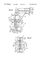
- FIG. 4I is a transverse vertical sectional view along section line 4 I— 4 I in FIG. 4 ′ through an ultrasonic horn assembly which sets a sharp fold in the side edges of the preformed web;
- FIG. 4J is a perspective view showing in more detail a portion of the stress-relieving station of the production line of FIG. 4 ′, which includes a heated cambered plate over which the re-formed web is fed;
- FIG. 4K is a longitudinal vertical sectional view along section line 4 K— 4 K in FIG. 4J through a pair of drive and nip rollers at one end of the cambered plate;
- FIG. 4L is a transverse vertical sectional view along section line 4 L— 4 L in FIG. 4 K through the nip roller assembly;
- FIGS. 4M and 4N show a modification of the production line of FIG. 4, where a number of multi-substrate webs are simultaneously formed on a number of production lines formed of common elements as in FIGS. 4 and 4 ′;
- FIG. 4O shows the different elements of a sonic horn used throughout the production lines to be described hereafter;
- FIG. 5 is a block diagram showing how a multi-substrate web formed by the production line of FIGS. 4 and 4 ′ is further processed by applying adhesive to the web, cutting the web into strips, and then stacking the strips to form a completed continuous cellular panel;
- FIG. 6 is a perspective view of two adjacent tubular sections of a panel where each tubular section is an open top tube for a panel which covers a window in its normal use and is raisable to the top of a window when not in use;
- FIG. 6A is a fragmentary enlarged vertical sectional view through the laminated portions of two adjacent tubular sections of the panel of FIG. 6 and shows spaced adhesive bands which secure together the adjacent wall sections of the tubular sections of the panel;
- FIG. 7 is a larger perspective view of one of the tubular sections shown in FIG. 6, specifically showing the adhesive bands on the top of each tubular section;
- FIGS. 8A-8F respectively show the different operations performed on a production line upon a pair of superimposed continuous substrate sheets of different material to form a multi-substrate sheet web which is wound upon a reel and then subsequently unwound and applied to the second section of a production line where the web is folded, coated with adhesive and cut into strips which are then laminated to form the continuous cellular panel shown in FIG. 6;
- FIG. 9 shows part of a production line for performing the various steps which form the multi-substrate sheet web of FIGS. 8A-8F;
- FIG. 10 is a block diagram showing how the multi-substrate web formed by the production line of FIG. 9 is further processed by folding the multi-substrate web, applying adhesive to the web, cutting the web into strips and then stacking the strips to form a completed continuous cellular panel of FIG. 6;
- FIG. 11 is a perspective view of three adjacent cells of yet another embodiment of the present invention which is a light-controlling cellular panel and is adapted to applications where the front and rear sides of the panel are movable vertically relative to one another from the light-passing position of FIG. 11 to one (not shown) where light passage through the panel is blocked;
- FIGS. 11A-11B more clearly show the spaced bands of adhesive which secure together the adjacent cells or tubular sections of FIG. 11;
- FIGS. 12A-12D respectively show the different operations performed on a production line upon three superimposed continuous substrate sheets of different material to form a multi-substrate sheet web which is to form a light-controlling cellular web which is wound upon a reel and then subsequently unwound and applied to the second section of a production line shown in block form in FIG. 14, where the web is folded, coated with adhesive, and cut into strips which are then laminated to form the continuous cellular panel of FIGS. 11 and 12;
- FIG. 13 shows part of a production line for performing the various steps which form the multi-substrate sheet web of FIGS. 12A-12D;
- FIG. 14 is a block diagram showing how the multi-substrate web formed by the production line of FIG. 13 is further processed by folding the multi-substrate sheet web, applying adhesive to the web, cutting the web into strips and then stacking the strips to form the completed continuous cellular panel of FIG. 11;
- FIGS. 14A-14D illustrate the tubular web produced by the production line of FIG. 13 respectively, before the web is folded, after it is folded, after adhesive is applied to it, and after strips cut from it are laminated together;
- FIG. 15 is a perspective view of a plurality of cells of another light-controlling panel embodiment of the present invention.
- FIGS. 15A-15B are fragmentary enlarged views of the panel of FIG. 15 showing the adhesive bands connecting adjacent multi-substrate strips which form the cells of the panel;
- FIG. 16 is the multi-substrate web produced by the production line in FIG. 13 coated with bands of adhesive;
- FIG. 17 shows a plurality of strips cut from the web of FIG. 16 and laterally shifted with respect to each other, with arrows indicating the points where the adhesive band coated on the strip will adhere the laterally shifted strips together, to form the light-controlling cellular panel of FIG. 15;
- FIG. 18 is a block diagram showing how the multi-substrate web formed by the production line of FIG. 13 is further processed to form the light-controlling cellular panel of FIG. 15;
- FIG. 19 shows the strip delivery and lateral strip-shifting conveyor means used to laminate the multi-substrate strips together to form the light-controlling cellular panel of FIG. 15 .
- FIG. 1 shows a portion of a non-light controlling closed tube cellular panel 10 in its expanded state, formed from laminated horizontally elongated vertically aligned tubular sections or cells 12 .
- FIG. 2 shows a single cell or tubular section 12 of the cellular panel 10 .
- the cell 12 has a front wall portion 14 made from a first continuous thermoplastic substrate sheet 18 , having a desired aesthetic appearance, and a rear wall portion 16 made from a second continuous thermoplastic substrate sheet 20 of about the same thickness, length and width as the first sheet 18 .
- the second sheet 20 is made of different appearing, preferably much less expensive, light-reflecting material from the substrate sheet 18 .
- the cell 12 also has a top wall portion 15 and a bottom wall portion 17 .
- Each tubular section 12 is laminated to the next adjacent tubular section 12 by spaced bands 11 - 11 ′ of adhesive which are spaced apart to provide an adhesive-free band 15 a centered on the top wall portion 15 of each cell 12 to receive a drill for drilling pull cord-receiving holes (not shown).
- Folds 13 - 13 ′, shown in FIG. 1A are formed in the centers of the sheets 18 and 20 , so that when the tubular sections 12 are expanded by the weight of a bottom rail (not shown) and the weight of the panel itself above the rail, the cells have a hexagonal shape.
- the cell 12 is initially formed by first superimposing the two separate continuous substrate sheets 13 , 20 as shown in FIG. 3 A.
- the superimposed substrate sheets 18 and 20 have superimposed longitudinal marginal portions adjacent their longitudinal edges 22 , 22 and 22 ′, 22 ′ which are secured together, most preferably by sonic welding.
- circular pointed slit/weld anvils 24 , 24 ′ are positioned slightly inward of the aligned pairs of longitudinal edges 22 , 22 ′ of the two substrate sheets 18 , 20 .
- the anvils 24 , 24 ′ may be driven by a pulley system (not shown) or other drive means or can be stationary. Driven rotary anvils are preferred to lessen the wear on the anvils.
- each anvil 24 , 24 ′ is tapered on each side 24 b , 24 b ′ toward the pointed edge 24 a , 24 a ′ thereof.
- a common ultrasonic horn 26 having a flat end face 26 a is positioned under the second substrate sheet 20 and extends at least the entire width of the two substrate sheets 18 , 20 .
- 3C is an enlarged view of a weld formed by the process shown in FIG. 3 B and shows the pointed edge 24 a ′ of the anvil 24 ′, the superimposed substrate sheets 18 , 20 , and a portion of the ultrasonic horn 26 positioned therebelow.
- the slit/weld anvils 24 , 24 ′ also slit through the superimposed substrate sheets 13 , 20 at the location of the anvil pointed edges 24 a , 24 a ′. This produces selvedge portions 32 , 32 ′ of the superimposed substrate sheets 18 , 20 adjacent the pointed edge 24 a , 24 a ′ of each slit/weld anvil 24 , 24 ′ which are collected in a process to be described in more detail.
- the welding process described forms a continuous, flat, multi-substrate tubular web 30 (FIG. 3B) in a horizontal plane, with the different appearing substrate sheets 18 , 20 constituting the opposite flat sides thereof.
- the panel 10 is formed from longitudinally spaced segments cut from this web 30 and laminated preferably in a manner to be described.
- the web 30 shown is reformed so that a flat tubular web 30 ′ (FIG. 3F) is formed having the welded portions 28 , 28 ′ thereof on the top and bottom of the opposite flat sides of the reformed flattened web 30 ′.
- the tubular web 30 is first guided from a horizontal plane to a vertical plane (FIG. 3 D).
- the flat tubular web 30 is next opened and then flattened in a plane approaching a right angle to the original plane of the flat web 30 to bring the welded portions 28 - 28 ′ to the flat top and bottom faces of the reformed tubular web 30 ′, but laterally spaced in opposite directions from the center line of the web so the welded portions 28 - 28 ′ webs are not in alignment, as shown in FIG. 3 E.
- the reformation of the web 30 causes the welded portions 28 - 28 ′ to project above and below the top and bottom faces of the reformed web 30 ′.
- the reformed tubular web 30 ′ have a similar thickness throughout; therefore, the projecting welded portions 28 - 28 ′ of the tubular web 30 ′ are flattened to produce a tubular web 30 with similar thickness throughout as shown in FIG. 3 F.
- FIG. 3E illustrates this weld flattening process which utilizes a weld flattening ultrasonic horn 33 , similar to the welding ultrasonic horn 26 shown in FIG. 3B, but positioned above the reformed tubular web 30 ′, and a preferably driven cylindrical rotating anvil 34 positioned below the reformed tubular web 30 ′.
- the tubular web 30 ′ masses between the web flattening ultrasonic horn 33 and the cylindrical rotating anvil 34 , the welded portions 28 , 28 ′ of the tubular web 30 ′ are flattened by the pressure applied by the flattening ultrasonic horn 33 vibrating the tubular web 30 ′ over the cylindrical rotating anvil 34 .
- the opposite top and bottom layers of the tubular web 30 ′ are not welded together because the conditions of the process are controlled to avoid a welding operation. Exemplary weld flattening conditions are disclosed in the process specification to follow.
- FIG. 3F shows the reformed tubular web 30 ′ with the welded portions 28 , 28 ′ out of alignment and substantially flattened. As shown, slight bulges 36 , 36 ′ remain in the tubular web 30 ′ at the welded portions 28 - 28 ′.
- FIGS. 4 and 4 ′ show a full production line for manufacturing the closed reformed tubular web 30 ′ made of two continuous substrate sheets 18 , 20 of differently appearing material.
- FIG. 4 ′ is a continuation of the line shown in FIG. 4 .
- Narrow webs of the two continuous substrate sheets 18 , 20 wound on driven supply reels 40 , 42 are unwound by the pulling force of drive and nip rollers 35 , 37 .
- the substrate sheets 18 , 20 pass through a series of rollers designed to maintain tension in the substrate sheets 18 , 20 .
- the substrate sheets 18 , 20 first respectively pass over idler rollers 44 , and down under conventional dancer tensioning rollers 46 which are mounted on arms (not shown) which move up and down to keep a constant tension in the continuous substrate sheets 18 , 20 .
- dancer tensioning rollers 46 which are mounted on arms (not shown) which move up and down to keep a constant tension in the continuous substrate sheets 18 , 20 .
- the tendency of these and other dancing rollers, to be described, to move up and down is opposed by a feedback control system which controls the driving speed of the supply reels 40 , 42 and take-up reel 128 upon which the completed web 30 is wound.
- the substrate sheets 18 , 20 continue over second idler rollers 48 .
- the first substrate sheet 18 passes through a conventional photo-cell controlled edge guidance roller assembly 50 which keeps the sheet in longitudinal alignment.
- the substrate sheet 18 next passes under a third idler roller 52 and to a pair of idler rollers 60 - 62 .
- the roller assembly 50 includes a support frame 50 ′ mounted for pivotal movement about a vertical axis and photo-cells 50 ′′ sensing the positions of the edges of the substrate sheet 18 .
- the second substrate sheet 20 After passing over the second idler roller 48 , the second substrate sheet 20 passes under the third idler roller 52 and through a conventional photo-cell controlled edge guidance roller assembly 50 , like the assembly 50 just described.
- the substrate sheet 20 then passes up to the pair of idler rollers 60 , 62 .
- the superimposed substrate sheets 18 , 20 have their longitudinal margins or edges aligned.
- the two superimposed substrate sheets 18 , 20 next pass through adjustable longitudinally-spaced non-rotating shafts 54 , 56 , 58 , which are vertically adjustable.
- the shafts 54 , 56 adjust the elevation of the two superimposed substrate sheets 18 , 20 .
- the shaft 58 is positioned below shafts 54 , 56 and is vertically adjustable to control tension in the substrate sheets 18 , 20 to eliminate any wrinkles at the welding assembly.
- the first substrate sheet 18 passes over the shaft 54 and between the shafts 56 and 58 .
- the second substrate sheet passes under the shaft 54 and between the two shafts 56 and 58 .
- the superimposed substrate sheets 18 , 20 next pass between the common ultrasonic horn 26 and the rotating or stationery slit/weld anvils 24 , 24 ′, where the sheets' opposite longitudinal edges 22 , 22 ′ are welded together, as previously described with respect to FIGS. 3B-3C.
- This forms a continuous tubular web 30 of differently appearing substrate sheets 18 , 20 superimposed and welded together in the horizontal plane.
- the welding process carried out by the ultrasonic horn 26 and rotating slit/weld anvils 24 , 24 ′ produce selvedge portions 32 , 32 ′ at the longitudinal edges 22 , 22 ′ of the tubular web 30 .
- the tubular web 30 and selvedge portions 32 , 32 ′ then pass through a pair of slit sensor pins 59 , 59 .
- the pair of slit sensor pins 59 , 59 are further shown in FIGS. 4A and 4B and extend upward from a common controlled shaft 59 ′.
- the sensor pins 59 , 59 pass between the selvedge portions 32 , 32 ′ and the welded portions 28 , 28 ′ of the substrate sheet 18 , 20 before the same reaches the rollers 35 , 37 .
- the sensor pins 59 , 59 detect whether the slit/weld anvils 24 , 24 ′ have completely slit through the substrate sheets 18 , 20 which would normally indicate that the slit/weld anvils 24 , 24 ′ are operating properly.
- the slit/weld anvils will wear over time and eventually fail to completely slit through the substrate sheets 18 , 20 . If this occurs, the portion of the substrate sheets 18 , 20 not slit engages the slit sensor pins 59 , 59 , which will rotate the common controlled shaft 59 ′ forward. As shown in FIG. 4B, this forward rotation of the shaft 59 ′ is connected to a switch means 61 which shuts down the production line so that the worn, defective slit-weld anvil can replaced.
- the tubular web 30 and selvedge portions 32 , 32 ′ next pass between a driven bottom roller 35 and a top nip roller 37 , which pull the substrate sheets 18 , 20 through the welding assembly.
- the selvedge portions are wound on take-up reel 64 .
- the tubular web 30 then passes over an idler roller 63 which restores the elevation of the tubular web 30 to the elevation occupied by the tubular web 30 at the welding apparatus.
- web-reforming means are provided which transition the welded portions 28 , 28 ′ of the tubular web 30 from the outer edges of the tubular web 30 to positions on top and bottom of a flat reformed tubular web 30 ′, as shown in FIG. 3 E.
- This transition of the welded portions 28 , 28 ′ preferably takes place in the specific manner illustrated in FIGS. 4C-4H.
- the tubular web 30 lies in a horizontal plane after exiting the ultrasonic horn 26 and slit/weld anvil 24 , 24 ′ assembly and is twisted into a vertical plane by passing through one of the vertical slots 67 formed between a first pair of spaced vertical rods 68 , 68 of a first comb-like structure 66 shown in FIGS. 4 ′ and 4 C.
- the vertical, horizontally spaced rods 68 are mounted on a base 66 supported on a post 67 .
- the tubular web 30 then passes through a second comb-like structure 66 ′ identical to the first comb-like structure 66 .
- Using two comb-like structures assures the tubular web 30 is kept in a vertical plane before it enters the next steps of the process; it also reduces stress on the web 30 .
- the vertically oriented tubular web 30 is then expanded to receive an insert structure 70 illustrated in greater detail in FIGS. 4D-4G.
- the insert structure 70 floats within and keeps the tubular web 30 open, with the welds 28 , 28 ′ at the top and bottom of the web 30 .
- the tubular web 30 is then re-flattened in a plane slightly less than 90 degrees from the plane of the interfaces between the substrate sheets 18 , 20 when they were originally welded together.
- FIG. 4E shows the insert structure 70 including a pair of horizontally spaced vertical support plates 72 , 72 ′ between which are rotatably mounted two narrow, vertically spaced rollers 74 , 76 having outwardly tapering peripheral portions 74 a , 76 a ending at peripheral flat crown portions 74 b , 76 b.
- a horizontal, rearwardly tapering guidance plate 78 is secured to the vertical support plates 72 , 72 ′ and extends forwardly therefrom. The tapered guidance plate 78 rests on a stationary shaft 86 for support.
- 4F illustrates in dashed lines a cross-section of the tubular web 30 passing around the insert structure 70 , with the flat crown portions 74 b , 76 b of the roller peripheries engaging and expanding the open web, so that the welded portions 28 , 28 ′ at the top and bottom of the vertically oriented tubular web 30 ride along the flat crown portions 74 b , 76 b.
- a pair of rotatable plate-holding members 78 ′ are positioned on opposite sides of the guidance plate 78 .
- the members 78 ′ rotate while pressing against the cuter sides of the web against the edge of the guidance plate 78 as shown in FIGS. 4 ′ and 4 F.
- the expanded web 30 is then kept expanded in a horizontal plane by the guidance plate 78 and in a vertical plane by the flat crown portions 74 b , 76 b of rollers 74 , 76 .
- a pair of fixed cylindrical outer guide members 77 , 79 are provided with tapered slotted portions 81 a , 83 a which closely but in spaced relation confront the forwardly facing sides of the rollers 74 , 76 respectively at the upper and lower margins thereof.
- the outer guide members 77 , 79 are formed by a pair of bearings 77 a-b, 79 a-b with tapered confronting surfaces 77 a′-b ′ and 79 a′-b ′ which are spaced apart by O-rings 81 , 83 and define grooves 81 a , 83 a with the tapered surfaces 77 a′-b, 79 a′-b ′ closely confronting the flat crown portions 74 a′-b, 76 a-b of the rollers 74 , 76 of the insert structure 70 .
- FIG. 4G is a view of the top portion of FIG. 4 E. It shows the welded portion 28 riding along the flat crown portion 76 b as the web 30 passes between the roller 76 and outer guide member 77 .
- the web 30 passes between a stationary grooved sleeve 86 ′ and a stationery grooved sleeve 87 ′.
- the insert structure guide plate 78 rests on the stationary shaft 86 .
- the sleeves 86 ′, 87 ′ are secured by one or more set screws 86 ′′, 87 ′′ to stationary shafts 86 , 87 .
- the shaft 87 is vertically adjustable and is located slightly downstream and above the shaft 86 . As best seen in FIG.
- the sleeves 86 ′, 87 ′ have laterally offset grooves 88 , 89 into which the bulging welded portions 28 , 28 ′ of the web 30 enter respectively, to laterally offset the welded portions 28 , 28 ′.
- This lateral offset reduces the thickness of the completed cellular panel 10 when in a collapsed configuration because the welded portions 28 , 28 ′ slightly bulge the tubular web 30 .
- the grooved sleeves 86 ′, 87 ′ are positioned by set screws 86 ′′ and 87 ′′ to obtain the desired offset positions.
- the stationary shafts 86 , 87 may carry additional grooved sleeves if manufacturing a plurality of webs at the same time, as seen in FIGS. 4M and 4N.
- the web 30 after leaving the grooved sleeves 86 ′, 87 ′, enters the weld flattening assembly comprising the flattening ultrasonic horn 33 and cylindrical rotating anvil 34 shown in FIG. 3 E.
- the top and bottom welds 28 , 28 ′ are located to the right and left of center lines of the top and bottom walls of the reformed web 30 ′, as shown in FIG. 3 E.
- the reformed tubular web 30 ′ passes between the flattening ultrasonic horn 33 and cylindrical rotating anvil 34 shown in FIG. 3E which flattens the projecting weld 28 , 28 ′ of the reformed tubular web 30 ′ to produce a web of similar thickness throughout.
- the reformed web 30 ′ passes between another ultrasonic horn 92 and a cylindrical rotating anvil 94 similar to the weld flattening assembly previously described.
- This second ultrasonic horn 92 vibrates the reformed web 30 ′ against the second cylindrical rotating anvil 94 to set the folds made at the outer longitudinal edges of the reformed web 30 ′.
- the second cylindrical rotating anvil 94 has a recessed portion 96 substantially at its center where the welded portions 28 , 28 ′ pass through.
- the bulging welded portions of the web 30 ′ would become heated to a much higher temperature than the rest of the web, which could cause a possible undesired welding together of the overlying layers of the web. This prevents the second ultrasonic horn from working directly onto the welded portions 28 - 28 ′ and concentrates the work performed on the longitudinal edges of the reformed web 30 ′.
- the nip roller 112 is a bias controlled roller.
- the nip roller 112 is, thus, adjustable allowing the nip roller 112 to apply more pressure to one side of the reformed web 30 ′ than the web's other side.
- Such a roller improves the control over the path of the web.
- the thicknesses of the substrate sheets 18 , 20 forming the web 30 ′ can be different. Due to this possible variation in thickness, the web may try to move laterally as it passes between the drive and the nip rollers 110 , 112 .
- the bias control nip roller 112 prevents any lateral movement of the web 30 ′ and assures the web 30 ′ travels in a straight path.
- FIGS. 4K and 4L illustrate the bias control nip roller 112 in more detail.
- FIG. 4K is a side view of the nip roller 112 taken along the line 4 K— 4 K in FIG. 4 J.
- FIG. 4L is a cross-sectional view taken along the line 4 L— 4 L in FIG. 4 K.
- the nip roller 112 has a grooved sleeve 130 which rides about a plurality of bearings 131 adjacent a common shaft 132 .
- the grooved sleeve has outer sections 133 , 134 which contact the reformed web 30 ′.
- the grooved sleeve 130 allows the welded portions 28 , 28 ′ to pass without contacting the nip roller 112 .
- Spring assemblies 135 , 136 located on each end of the shaft 132 , apply pressure independently to each outer section 133 , 134 of the nip roller 112 .
- Set screws 137 , 138 allow the pressure to be adjusted on each outer section 133 , 134 of the nip roller 112 . As described before, more pressure can then be applied to one side of the reformed web 30 ′ than the other to prevent any lateral movement of the web 30 ′ due to the different thicknesses of the substrate sheets 18 , 20 .
- the web 30 ′ is next pulled under tension over a heated upwardly honed or cambered plate 106 , as shown in FIG. 4 ′ and FIG. 4J, to relieve the stresses produced in the flattened welded portions 28 , 28 ′ of the reformed tubular web 30 ′.
- the cambered plate 106 is heated by a heating element 108 positioned below the plate.
- the tubular web 30 ′ is forced downward against the heated cambered plate 106 by the passage or the web 30 ′ between drive and nip rollers 110 , 112 , the nip roller 112 being positioned below the lower inlet end of plate 106 and then between drive and nip rollers 116 , 114 at the outlet end of the plate 106 as seen in FIG. 4 ′ and FIG. 4 J.
- Nip roller 114 is also a bias control roller, identical to nip roller 112 , to assure the web passes over the upwardly honed cambered plate 116 in a straight path.
- Heating the reformed tubular web 30 ′ under tension relieves stresses produced in the welded portions 28 , 28 ′ of the tubular web by the welding process. These stresses are apparent by a longitudinal bow in the reformed tubular web 30 ′ and ripples at the welds 28 , 28 ′ prior to passing over the heated cambered plate 106 . The relief of these stresses in the welds 28 , 28 ′ minimizes any ripples and produces a flat, unbowed tubular web 30 ′.
- the reformed tubular web 30 ′ passes under a further idler roller 118 , over an adjacent idler roller 120 and passes under a dancer tensioning roller 122 which controls tension in the web 30 ′.
- the web 30 ′ proceeds over the two idler rollers 124 , 126 to an individual powered take-up reel 128 for later fabrication, as shown in FIG. 4, or is immediately processed to form the cellular panel 10 .
- FIGS. 4A-4L show the manufacture of only one tubular web 30 at a time
- the comb-like structure 66 (FIG. 4N) has a plurality of vertical rods 68 to receive a number of tubular webs 30 a- 30 d simultaneously.
- Such a modified production line is shown in FIG. 4 M.
- a number of tubular webs 30 a- 30 d can be manufactured from a wider, continuous tubular web of a pair of supplemental continuous substrate sheets 18 a , 20 a.
- the continuous substrate sheets 18 a , 20 a are unwound from powered supply reels (not shown) and pass through a similar set of rollers (like rollers 44 through 60 ), as shown in FIG. 4 . These rollers are wider, however, to accommodate the wider substrate sheets 18 a , 20 a.
- the superimposed wider substrate sheets 18 a , 20 a then are passed between a common ultrasonic horn 26 ′ vibrating the wider superimposed substrate sheets 18 a , 20 a against a plurality of laterally spaced rotating slit/weld anvils 24 ′ positioned adjacent to one another.
- Exemplary specifications for some of the production lines described include a sonic horn like that shown in FIG. 4 O.
- the sonic horn is connected to a booster B 1 driven by a converter C 1 which is fed from a commercial AC power line.
- substrate sheet 18 0.007′′ thick woven polyester fabric.
- substrate sheet 20 0.007′′ thick non-woven polyester fabric.
- a. power supply converts 50/60 Hz line current to 20 KHz electrical energy
- c. booster (1:2 ratio); modifies the amplitude of vibrations.
- amplitude 65% setting at power supply control
- function of horn shape peak to peak displacement of the horn at its work face.
- slit/weld anvil 24 stationary, 1′′ diameter, 1 ⁇ 8′′ wide, 150 degrees, 0.005 r.
- a. power supply converts 50/60 Hz line current to 20 KHz electrical energy
- b. converter converts electrical oscillations into mechanical vibrations.
- c. booster (1:1.5 ratio); modifies the amplitude of vibrations.
- grooved guide rollers 77 , 79 7 ⁇ 8′′ diameter, ⁇ fraction (1/16) ⁇ ′′ spacing (o-ring), 17 ⁇ 8′′ vertical distance between upper and lower pairs.
- guide plate 78 0.030′′ thick, ⁇ fraction (9/16) ⁇ ′′ to 1 ⁇ fraction (5/16) ⁇ ′′ taper over 91 ⁇ 2′′ distance.
- a. power supply converts 50/60 Hz line current to 20 KHz electrical energy
- c. booster (1:1.5 ratio); modifies the amplitude of vibrations.
- foldsetting cylindrical anvil 94 4′′ diameter, driven at 17.85 feet per minute (2% overdrive for web tensioning) with weld seam clearance relief.
- nip rollers 112 , 114 11 ⁇ 8′′ wide, 2′′ diameter, 1 ⁇ 4′′ wide groove.
- heated cambered plate 106 230 degrees F., 1 ⁇ 2′′ rise at center 24′′ length.
- FIG. 5 is a block diagram illustrating the steps of forming a cellular panel 10 , from a continuous flat reformed tubular web like web 30 ′, 30 a , 30 b , 30 c or 30 d.
- the functions performed by the blocks shown therein may be performed, for example, by the tension control web aligning, adhesive applying, and web cutting and stacking chamber disclosed in U.S. Pat. No. 4,450,027 or copending Application Ser. No. 07/839,600 filed Feb. 28, 1992.
- a pair of reels of a pair of reformed webs 30 a and 30 b ′ are shown in FIG. 5 supported one above the other.
- the web 30 a ′ on one reel is unwound in a horizontal plane while it passes first through tension control and web aligning means 41 comprising rollers (not shown) to maintain tension and laterally align the tubular web 30 a ′.
- the tubular web 30 a ′ then passes through an adhesive applying means 43 which applies the two bands 11 , 11 ′ of adhesive, (FIG. 1 ).
- the two bands of adhesive 11 , 11 ′ are applied to the portion of the web 30 a ′ to form the top wall portion 15 of each cell 12 formed from the tubular web 30 a ,(FIG. 2 ). As shown in FIG.
- the bands of adhesive 11 , 11 ′ are applied over the welded portions 28 , 28 ′ of the tubular web 30 a ′ to reinforce the welds.
- the bands of adhesive 11 , 11 ′ are spaced to leave the center portion of the top wall portion 15 of the tubular web 30 a ′ free of adhesive. This allows for drilling through the center of the top wall portion 15 of the tubular web 30 ′ to accommodate the drawstrings of a complete cellular panel 10 without the drilling means coming into contact with the adhesive. If adhesive was applied along the entire top wall portion 15 , the drilling means would have to be periodically cleaned or replaced after the adhesive built up on the drilling means.
- the tubular web 30 a ′ is then cut into identical tubular strips by a cutting means 45 .
- the strips cut from the web 30 a ′ form the cells or tubular sections 12 of the panel 10 .
- the web 30 a ′ is then fed by high speed conveyor means 47 to a stacking chamber 49 , both similar to that disclosed in U.S. application Ser. No. 839,600.
- the stacking chamber 49 receives the flat tubular strips through a strip pass-through slot (not shown) located in the floor of the stacking chamber extending the length of the tubular strips.
- the conveyor means 47 includes a stationary conveyor belt section 47 a which separates the cut strips and a raisable conveyor section 47 b which is raised by a lifter means 51 .
- the conveyor sections 47 a , 47 b may each include suction conveyor belts which hold the strips by suction thereon.
- the lifter means 51 raises the raisable conveyor 47 b through the slot in the floor of the stacking chamber 49 . This pushes the strip, held on the belts by suction, off the belts and up against the strip above it. This strip is thus raised in the stacking chamber 49 , so that the adhesive bands 11 , 11 ′ adhere to the bottom of the strip above it, as shown in FIG. 1 A.
- the movement of the belt forming the raisable conveyor 47 b is stopped when a strip is in alignment along its length with the inlet slot of the stacking chamber 49 .
- the bottom of the stacking chamber may be defined by a pair of vertical confronting walls (not shown) which are spaced apart a distance slightly greater than the width of the strips. These walls thus laterally align each strip being pushed into the stacking chamber with the strip above it.
- the upper portion of the stacking chamber preferably has opposite upwardly diverging walls so that the laminated strips raised momentarily in the chamber will not get stuck in the chamber.
- the lifter means 51 lowers the raisable conveyor 47 b which passes down through the pass-through slot in the bottom of the stacking chamber 49 .
- the strip just stacked separates from the raisable conveyor as it is pulled against the floor of the chamber 49 by the downward movement of the raisable conveyor 47 b.
- the movement of the belt of the raisable conveyor 47 b then resumes as it receives the next strip to be pushed into the stacking chamber 49 .
- the sequence of operation just described is repeated to form the expandable cellular panel 10 in a mass production operation.
- a photo cell (not shown) senses this condition and stops the web feed.
- the leading edge of the other reel, for web material 30 b ′ is then spliced to the trailing edge of the completely unwound web 30 a′.
- FIGS. 6-10 illustrate another embodiment of the present invention where a non-light controlling cellular panel 10 ′ is made similar to the panel 10 shown in FIG. 1, except that it is formed from a plurality of horizontally elongated open top tubular sections 12 ′ or cells rather than closed tubular sections.
- FIG. 6 shows a portion of such a cellular panel 10 ′.
- each tubular section 12 ′ is formed of front and rear substrate sheets 18 ′, 20 ′ of two differently appearing substrate materials.
- Each tubular section 12 ′ has a top wall portion 15 ′, formed by spaced inturned longitudinal margins of the substrate sheets 18 ′ and 20 ′, a bottom wall portion 17 ′ formed by the opposite longitudinal margins of the substrate sheets welded together at 28 a, and front and rear wall portions 14 ′ and 16 ′ respectively formed by the sheets 18 ′ and 20 ′.
- Each tubular section 12 ′ is formed from strips cut from a folded continuous two-substrate web formed by folding the initially flat web 31 , (FIG. 8 F). The outer longitudinal marginal portions of the unfolded continuous multi-substrate web 31 are folded over the central portion of the web to form an open tubular flat web which is coated with adhesive, cut into strips, and the adhesive-coated strips are sequentially stacked.
- the flat web 31 is made in the manner shown in FIGS. 8A-F.
- FIG. 8A shows two differently appearing substrate sheets 18 ′, 20 ′ with their opposite longitudinal edges 22 , 22 ′ aligned.
- FIG. 8B shows the substrate sheets 18 ′, 20 ′ superimposed with only one of their aligned longitudinal edges 22 , 22 ′ being welded together at 28 a.
- the substrate sheets 18 ′, 20 ′ pass between a preferably driven rotating slit/weld anvil 24 and an ultrasonic horn 26 .
- This assembly is similar to that used in the welding process described with respect to the closed tubular web 30 in FIGS. 1-5.
- the ultrasonic horn 26 vibrates against the rotating slit/weld anvil 24 , welding the substrate sheets 18 ′, 20 ′ together to form a continuous folded tubular web 31 open at one end.
- This process produces a selvedge portion 32 ′ which is collected.
- the web is then unfolded to form the flat web 31 shown in FIG. 8 D and the weld 28 a is flattened by a flattening ultrasonic horn 33 pressing the downwardly projecting weld against a cylindrical driven rotating anvil 34 , as shown in FIG. 8 E.
- the cylindrical rotating anvil 34 is driven.
- the weld flattening process just described leaves just a slight bulge 36 in the open multi-substrate web 31 .
- FIG. 9 illustrates a portion of the production line utilized in manufacturing the open tubular web 31 .
- the production line has two powered supply reels 40 ′, 42 ′ of the substrate sheets 18 ′, 20 ′ made of different material.
- the substrate sheets 18 ′, 20 ′ pass through an identical roller set up (not completely shown) as previously discussed for the closed tubular web 30 which tensions the substrate sheets 18 ′, 20 ′ and superimposes the opposite longitudinal edges 22 , 22 ′ of the substrate sheets 18 ′, 20 ′.
- the substrate sheets 18 ′, 20 ′ are then welded together at one of their aligned longitudinal edges 22 , 22 ′ by the vibrating ultrasonic horn 26 and slit/weld anvil 24 assembly, as previously described with respect to FIG. 8 B.
- the selvedge portion 32 ′ produced by the welding process is also wound upon a driven take-up reel 64 .
- a continuous open tubular web 31 is formed having different appearing substrate materials.
- the open tubular web then passes between drive roller 35 and nip roller 37 which pull the substrate sheets 18 ′, 20 ′ through the welding assembly 24 , 26 .
- the open tubular web 31 can also pass through slit sensor pins as described.
- the open tubular web 31 is then unfolded prior to entering the weld flattening assembly to form an unfolded flat multi-substrate web.
- the open tubular web 31 passes under a skewed roller assembly 75 made up of skewed top driven rollers 75 a , 75 a which exert outward forces on the web 31 and a driven bottom roller 75 b.
- the unfolded multi-substrate web 31 then passes between two idler rollers 81 , 33 , and under a dancer tensioning roller 85 , which controls tension in the web 31 by adjusting the speed of the driven supply and take-up reels 40 ′, 47 ′, 128 .
- the web proceeds over a further idler roller 87 before entering the weld flattening apparatus.
- the welded portion 28 a of the open multi-substrate web 31 is then flattened by the flattening ultrasonic horn 33 and cylindrical rotating anvil 34 , as previously described with respect to FIGS. 8C-8E.
- the flat open multi-substrate web 31 passes between drive and nip rollers 110 , 112 and over a heated cambered plate 106 to relieve the stresses produced in the welded portion 28 a of the is open multi-substrate web 31 from the welding process as seen in FIG. 9 .
- the heated cambered plate 106 is identical to that described in the embodiment for the closed tubular web 30 with respect to FIGS. 1-5.
- the heat subjected to the open multi-substrate web 31 relieves the stresses in the welded portion 28 a , thus minimizing ripples and producing a flat, as well as straight open multi-substrate web 31 , which then can be processed further with less difficulties.
- the open multi-substrate web 31 continues between drive and nip rollers 114 , 116 , and under a dancer tensioning roller 119 , which controls tension in the web 31 .
- the web 31 proceeds over an idler roller 121 to an individual powered take-up reel 128 for later fabrication as shown in FIG. 9, or is immediately processed to form the cellular panel 10 ′.
- FIG. 10 is a block diagram illustrating the steps in forming the open cellular panel 10 ′ of FIG. 6 formed from the flat web 31 . It is very similar to the process for making the cellular panel 10 formed by the closed tubular web 30 as previously discussed with respect to FIGS. 1-5. Accordingly, similar stations in FIG. 10 have been identically numbered to those in FIG. 6 . One difference is the addition of folding means 55 before the adhesive applying means 43 .
- a suitable folding means is disclosed in U.S. Pat. No. 4,450,027 or in U.S. application Ser. No. 08/040,869, filed on Mar. 31, 1993, entitled “Folding Plate Assembly For Fabricating Honeycomb Insulating Material” and filed in the names of Bryan K. Ruggles and Cary L. Ruggles.
- the folding means includes a slot folding plate assembly through which the web 31 passes.
- the slot is shaped to cause the outer longitudinal edges of the flat multi-substrate web 31 to raise above and over the central portion of the web 31 , thus folding the web.
- the confronting longitudinal margins of the folded web which form the top wall portion 15 ′ of the folded web do not contact one another, leaving a gap 57 in the top wall portion 15 ′ (FIG. 6 A).
- the folding means 55 may also include a fold setting means in the form of a heated drum (not shown) which heats the web material to its heat set temperature. The heated folded web is pressed against the drum to form sharp permanently set folds.
- a cooling means (not shown) then cools the pressed web below the setting temperature forming set pressed folds 13 , 13 ′ shown in FIGS. 6 and 7.
- the tubular web 31 next passes through adhesive applying means 43 which applies two bands of adhesive 11 - 11 ′ on the top wall portion 15 ′ of the open tubular web 31 (FIG. 7 ).
- the open tubular web 31 is then cut into identical tubular strips by cutting means 45 which, by conveyer means, are fed to a stacking chamber 49 which may be similar to that disclosed in U.S. application Ser. No. 07/839,600, as previously discussed in detail with respect to the closed tube cellular panel 10 of FIGS. 1-5.
- FIGS. 11-14 illustrate a light controlling cellular panel 10 ′′ of the present invention. It comprises horizontally elongated vertically aligned cells or tubular sections 12 ′′ formed from an open flat tubular web 30 ′′. The web 30 ′ is folded, coated with adhesive, and cut into strips; the strips are then stacked in the manner previously described. An opaque substrate sheet 19 ′′ in each tubular section 12 ′′ controls light passing through the panel 10 ′′. When the opaque substrate sheet 19 ′′ is rotated to a vertical plane, light passing through the panel is obstructed.
- FIG. 11 shows a portion of the light-controlling cellular panel 10 ′′.
- the cellular panel 10 ′′ is formed by laminating separate open tubular strips when in a flattened condition, as shown in FIGS. 14C and 14D, to form a tubular section 12 ′′.
- Each cell 12 ′′ has a front wall portion 14 ′′ made of a sheer substrate sheet 18 ′′ of one mesh size, a rear wall portion 16 ′′ made of a sheer substrate sheet 20 ′′ of a different mesh size, a bottom wall portion 17 ′′ made of a wider substrate sheet 19 ′′ of opaque material, and a top wall portion 15 ′′ which is formed by the bottom wall portion 17 ′′ of an adjacent cell 12 ′′ and the inwardly turned upper ends of the substrate sheets 18 ′′, 20 ′′ secured to the opaque sheet 19 ′′ by spaced bands of adhesive 11 ′′.
- the open tubular strips are first formed from a flat continuous web 30 ′′ made of three separate substrate sheets 18 ′′, 19 ′′, 20 ′′ (FIG. 12A) which are welded together along their longitudinal margins.
- FIG. 12A shows the three superimposed substrate sheets 18 ′′, 19 ′′, 20 ′′ with the left longitudinal edges 22 ′ and 22 ′′ of the wider central opaque substrate sheet 19 ′′ and lower sheer substrate sheet 20 ′′ aligned, and the right longitudinal edges 22 ′′ and 22 of the central opaque substrate sheets 19 ′′ and upper sheer substrate sheet 18 ′′ aligned.
- FIG. 12A shows the three superimposed substrate sheets 18 ′′, 19 ′′, 20 ′′ with the left longitudinal edges 22 ′ and 22 ′′ of the wider central opaque substrate sheet 19 ′′ and lower sheer substrate sheet 20 ′′ aligned, and the right longitudinal edges 22 ′′ and 22 of the central opaque substrate sheets 19 ′′ and upper sheer substrate sheet 18 ′′ aligned.
- the three-substrate sheets 18 ′′, 19 ′′, 20 ′′ are welded together at their aligned two-substrate thick longitudinal edges by passing the substrate sheets 18 ′′, 19 ′′, 20 ′′ between a common vibrating ultrasonic horn 26 and slit/weld anvils 24 identical to the welding apparatus as previously described.
- outer sheer substrate sheet 18 ′′ is welded to the wider opaque substrate sheet 19 ′′ at the right aligned longitudinal edges thereof while the other outer sheer substrate sheet 20 ′′ is simultaneously welded to the opaque substrate sheet 19 ′′ at the aligned left longitudinal edges thereof to form a Z-shaped web 30 ′′ which is unfolded, as shown in FIG. 12 C.
- the web 30 ′′ has a center opaque substrate sheet 19 ′′ and outer sheer substrate sheets 18 ′′, 20 ′′ all in the same plane.
- the welded portions 28 ′′ of the unfolded web 30 ′′ are flattened to form a flat web of similar thickness throughout.
- the welded portions 28 ′′ are flattened by passing the flat multi-substrate web 30 ′′ between the flattening ultrasonic horn 33 and cylindrical rotating anvil 34 .
- the pressure applied by the flattening ultrasonic horn 33 to the welded portions 28 ′′ of the multi-substrate web 30 ′′ against the cylindrical rotating anvil 34 flattens the welded portions 28 ′′ to produce a multi-substrate web 30 ′′ with similar thickness throughout.
- FIG. 13 shows a portion of the production line for manufacturing the continuous flat multi-substrate web 30 ′′.
- the production line begins with driven reels 40 ′′, 41 ′′ and 42 ′′ of continuous substrate sheets 18 ′′, 19 ′′ and 20 ′′ unwinding the sheet material therefrom.
- the substrate sheets 18 ′′, 19 ′′, 20 ′′ pass through similar sets of web-tensioning rollers (not shown) as discussed previously.
- the three-substrate sheets 18 ′′, 19 ′′, 20 ′′ are then superimposed with their longitudinal edges aligned as described, by passing them in superimposed relation between a pair of idler rollers 60 ′′, 62 ′′ with one outer sheer substrate sheet 18 ′′ on top, the center opaque substrate sheet 19 ′′ in the middle, and the outer sheer substrate 20 ′′ on the bottom of the superimposed stack of sheets.
- Each outer sheer substrate sheet 18 ′′, 20 ′′ is then simultaneously welded to the longitudinal edge of the center opaque substrate sheet 19 ′′ in alignment therewith by vibrating ultrasonic horn 26 and against the slit/weld anvils 24 , as previously described with respect to FIG. 12 B.
- the selvedge portions 32 ′′ produced by the welding process are also rewound by take-up reels 64 ′′.
- a Z-shaped web 30 ′′ is formed.
- the Z-shaped web passes between a drive roller 35 ′′ and a nip roller 37 ′′ which act to pull the substrate sheets 18 ′′, 19 ′′, 20 ′′ through the welding assembly.
- the web 30 ′′ can also pass through slit sensor pins as previously described with respect to the closed-tube cellular panel 10 .
- the Z-shaped web 30 ′′ is then unfolded before entering the weld flattening apparatus to form a flat substrate sheet.
- the Z-shaped web 30 ′′ passes beneath a skewed roller assembly 75 ′′ comprised of driven upper rollers 75 a ′′, 75 b ′′, 75 c ′′ and bottom roller 76 d.
- the driven rollers 75 a ′′ and 75 c ′′ overlying the outer sheet substrate sheets 18 ′′, 20 ′′ exert downward and outward forces on the outer sheer substrate sheets 18 ′′ and 20 ′′.
- a transversely extending roller 75 b ′′ overlying the central opaque sheet 19 ′′ exerts a downward force on the center opaque substrate sheet 19 ′′ passing beneath the same.
- the flat multi-substrate web 30 ′′ then passes over an idler roller 83 ′′, under a dancer tensioning roller 85 ′′ and over a second idler roller 87 ′′.
- the projecting welded portions 28 ′′ of the multi-substrate web 30 ′′ are then flattened by the flattening ultrasonic horn 33 and cylindrical rotating anvil 34 , as previously described with respect to FIG. 12 D.
- the flattened multi-substrate web 30 ′′ passes between drive and nip rollers 110 ′′, 112 ′′ and then over a heated cambered plate 106 to relieve the stresses produced in the welded portions 28 ′′ of the multi-substrate web 30 ′′ from the welding process.
- the heated cambered plate 106 is identical to that described in the embodiments of FIGS. 1-5.
- the multi-substrate web 30 ′′ then continues between further drive and nip rollers 114 ′′, 116 ′′, under a dancer tensioning roller 118 ′′ and over an idler roller 120 ′′ to either an individual driven take-up reel 128 ′′ for later fabrication as shown in FIG. 13, or immediately processed to form the cellular panel 10 ′′.
- FIG. 14 shows a block diagram illustrating the steps of forming the light controlling cellular panel 10 ′′ formed from the flat unfolded multi-substrate web 30 ′′. It is very similar to the process utilized to make cellular panel 10 ′ formed from an open tubular web in accordance with FIG. 10 . Accordingly, corresponding reference numerals are used in FIG. 14 to avoid a repetition of description.
- the folding means 55 ′ is different from the folding means 55 in FIG. 10 which forms sharp set folds 13 ′— 13 ′ in the web 31 ′.
- the folding means 55 ′ includes no heated drum or other means to set any folds so that, as shown in FIG. 11, there are no folds seen at the sides of the rectangular tubular sections.
- the folding means therefore, preferably includes only a slot forming plate, as shown in copending application Ser. No. 839,600.
- FIGS. 14 A— 14 D illustrate respectively transverse sections of the web 30 ′′ as it unwinds from the reel 128 ′′, and when it leaves the folding means 55 ′ and adhesive applying means 43 .
- the bands of adhesive 11 ′′— 11 ′′ deposited by the adhesive applying means 43 on the folded-over marginal portions of the outer substrate sheets 18 ′′ and 20 ′′ overlie the outer marginal portions of the opaque substrate sheet 19 ′′.
- FIG. 14D shows adjacent strips S 1 and S 2 cut from the web 30 ′′ pushed in the stacking chamber 49 where these strips are laminated together by the adhesive bands 11 ′′— 11 ′′.
- the cells or tubular sections have the rectangular shape shown therein.
- the outer sheer substrate sheets 18 ′′, 20 ′′ which form the front or rear wall portions 14 ′′ or 16 ′′ of the cellular panel 10 ′′
- the wide opaque substrate sheets 19 ′′ of the various laminated strips shift from a horizontal position where light passes through the cellular panel 10 ′′.
- the opaque substrate sheets 19 ′′ are then inclined upwardly to an upstanding position where the opaque substrate sheets 19 ′′ of adjacent strips overlap, because they are wider than the outer substrate sheets 18 ′′, 20 ′′. In this position, the passage of light through the panel 10 ′′ is prevented.
- FIG. 16 shows the multi-substrate web 30 ′′ with bands of adhesive B and B′ applied along the outer longitudinal margin, of the rear sheer substrate sheet 20 ′′, and along the front margin of the opaque sheet 19 ′′ opposite the inner or front margin of the sheer substrate sheet 20 ′′.
- the web 30 ′′ is then cut into strips sequentially to form three-substrate strips S 1 ,S 2 ,S 3 , etc. as shown in FIG. 17 .
- the closed tube cellular panel 10 ′′′ is formed by laminating in sequence the flat unfolded multi-substrate strips S 1 ,S 2 , etc. together in identically oriented positions at transversely spaced points therealong to the previously cut strip located above it.
- FIGS. 16 and 17 are fragmentary views of the portion of the cellular panel 10 ′′′ of FIG. 15, showing the adhesive connections of the identical multi-substrate strips when the panel is expanded.
- a light controlling panel 10 ′′′ is formed comprising horizontally elongated vertically aligned closed tubular cells 12 ′′′ as seen in FIG. 15 .
- each cell 12 ′′′ is formed by the front sheer substrate sheet 18 ′′ of one of the multi-substrate strips; the rear vertical wall 16 ′′′ or side of the cell 12 ′′′ is formed by the rear sheer substrate sheet 20 ′ of the multi-substrate strip above it.
- the bottom horizontal wall 17 ′′′ of each cell 12 ′′′ is formed by the center opaque substrate sheet 19 ′′ of said one strip; and the top horizontal wall 15 ′′′ of that cell is formed by the center opaque substrate sheet 19 ′′′ of the strip above it.
- the front and rear substrate sheets 18 ′′, 20 ′′ of each strip form respectively the front and rear wall portions of adjacent cells.
- the front substrate sheet of each strip is designated by the letter F
- the center opaque substrate sheet of each strip is designated by the letter C
- the rear substrate sheet of each strip is designated by the letter R, with the particular substrate sheet of a given strip being further identified by a reference number corresponding to the reference number identifying that strip.
- the forwardmost adhesive band of each strip is identified by the letter B′ and the rearmost adhesive band of each strip identified by the letter B, with the various adhesive bands of the various strips each identified by a number corresponding to the number of the particular strip involved.
- the various substrate sheets, adhesive bands of the various strips shown in FIG. 17 can immediately be identified in FIG. 15 .
- the adjustment of the panel 10 ′′′ to obtain the light passing and obstructing modes of operation is very similar to that of the open tube panel 10 ′′ of FIGS. 11-14.
- the center opaque substrate sheets 19 ′′ of the various strips of the cellular panel 10 ′′′ are pivoted from horizontal light-passing positions to upstanding light-blocking positions. Because the center opaque substrate sheets 19 ′′ are wider than the outer sheer substrate sheets 18 ′′, 20 ′′, the center opaque substrate sheets 19 ′′ overlap one another in their light-blocking upstanding positions, thus preventing any light from passing through the cellular panel 10 ′′′.
- FIG. 18 is a block diagram showing the different steps of manufacturing the cellular panel 10 ′′′ of FIG. 15 .
- the laminated multi-substrate strips forming a web 30 ′′ are unwound from a driven supply reel 128 ′′ and pass through tension control and web aligning means 41 ′.
- Adhesive bands B and B′ are applied by adhesive applying means 43 ′ to the multi-substrate web 30 ′′ and then the web 30 ′′ is cut by cutting means 45 into strips S 1 ,S 2 ,S 3 , etc.
- the multi-substrate strips are then carried by high speed conveyor means 47 , like that previously described to the raisable conveyer portion 47 b.
- the lifter means 51 ′ raises the raisable conveyor portion to where the first strip S 1 is laminated against a leader strip (not shown) carried by an overhead laterally indexable conveyor belt.
- the second strip S 2 is laminated to the first strip in the pattern described with respect to FIG. 17, and the process continues with the third strip S 3 , etc.
- the control means 53 ′ control the operating sequence of the stations of the production line just described.
- FIG. 19 shows part of the manufacturing apparatus for making the light controlling closed tube cellular panel 10 ′′′ of FIG. 15 .
- a conveyor belt 150 represented by the stationary conveyor block 47 a in FIG. 18, receives the multi-substrate strips S 1 , S 2 , etc.
- the conveyor belt 150 is provided with suction holes communicating with a vacuum source (not show) to hold the strips thereon.
- the conveyor belt 150 conveys the strips to the raisable conveyor belt 151 , represented by block 47 b in FIG. 18 .
- the raisable conveyor belt 151 also has suction holes 156 to allow a vacuum box 154 , shown in FIG. 19, to hold the multi-substrate strips in place.
- the first multi-substrate strip is laminated to a leader strip located on a laterally indexable conveyor belt 160 .
- the raisable conveyor 151 delivers the strip S 1 to the overhead laterally indexable conveyor belt 160 , represented by block 49 ′ in FIG. 18 .
- the laterally indexable conveyor belt 160 also has suction holes 151 ′ communicating with a vacuum box 164 to hold in place the first multi-substrate strip S 1 adhered thereto.
- strip location sensors (not shown) in the conveyer belt structure 152 relay the location of the second multi-substrate strip S 2 to the control means 53 ′ in FIG. 18 .
- the control means 53 ′ then indexes the laterally indexable conveyer belt 160 in the direction shown by the arrows in FIG. 19 to the proper location where it stops to receive the second multi-substrate strip S 2 delivered thereto.
- the raisable conveyer belt 151 is part of a structure connected to hydraulically operated portions 155 ′ of hydraulic cylinder 155 which then move the belt 151 upward to laminate the second substrate strip S 2 on raisable conveyer belt 151 against the first multi-substrate strip S 1 above it. This process continues with the subsequent strips.
- the belt 151 is then lowered by the pistons 155 ′.
- the sticking force of the adhesive bands B and B′not yet fully cured, is desirably greater than the vacuum force holding the strip on the belt. If not, vacuum pressure on the belt 151 ′ is momentarily cut-off.
- the laminated multi-substrate strips now forming a continuous web of laminated strips pass between the laterally indexable belt 160 and a nip roller 170 .
- the continuous web then passes over an idler roller 172 , under a dancer tensioning roller 174 , which tensions the newly formed web, and over another idler roller 176 to a driven take-up reel 178 .
- the speed of rewind reel 178 is controlled by the elevation of the dancer tensioning roller 174 .
Abstract
An expandable and contractible cellular panel 10 comprises a plurality of parallel, aligned, elongated tubular sections 12 secured together at the median region of their adjacent longitudinal margins to form the panel 10. The adjacent tubular sections 12 of the panel 10 are made of a pair of substantially identical separate strips of sheet material from those forming the other adjacent tubular sections 12. The various adjacent pairs of strips are laminated together along their confronting longitudinal margins. Each strip is made of at least two separate flexible substrate sheets 18,20 having completely different appearances, and are secured together by welding together their longitudinal margins. The corresponding substrate sheets 18,20 of all the strips have corresponding positions in the panel 10, so that all the substrate sheets having one appearance are on one side of the panel 10 and those having a different appearance are on the other side of the panel 10, and the welded portions 28,28′ are located in the laminated portion of the strips where they are hidden from view.
Description
This is a Continuation of U.S. patent application Ser. No. 08/880,569 filed Jun. 23, 1997 now U.S. Pat. No. 6,045,890 which is a Continuation of U.S. patent application Ser. No. 08/273,469 filed Jul. 11, 1994, abandoned.
The present invention relates to cellular insulation panels. It has one of its most important applications as an insulating panel for covering windows or other openings. These panels most commonly comprise a plurality of tubular sections adhesively secured together. The panel can be oriented so that the tubular sections form a horizontally contractible and expandable panel which extends vertically, such as when covering a doorway or other similar openings. The panel more commonly is used with an orientation where the tabular sections form a vertically collapsible and expandable panel extending horizontally, such as when covering a window.
In window covering, the panel is mounted upon a headrail with pull cords extending down through holes in the panel to a bottom rail secured to the bottom of the panel. In some panel designs, each tubular section is a strip of usually thermoplastic woven or unwoven sheet material folded into an open-top tube. Each tube-forming strip is initially completely separate from the other tubular strips forming the panel and is laminated to the adjacent strips of the panel by bands of adhesive. The folds of each tubular section are usually sharp or set so that they appear as lines or bands which improve the aesthetic appearance of the panel. Such a panel is disclosed in Dutch Published Application No. 6706563 published Nov. 11, 1968 to Landa. In this Dutch publication, the cells have a rectangular, hexagonal or a pointed oval shape, depending on the width of the adhesive bands and the degree of expansion of the cells. If the adjacent tubular sections are secured together over wide securement bands and are fully expanded, the cells have a rectangular shape, as is shown in U.S. Pat. No. 4,019,554 granted on Apr. 26, 1977 to Rasmussen.
In another form of cellular panel construction, a pair of zig-zag shaped sheets of material are placed into confronting relation and secured together at the abutting fold points, to form diamond-shaped cells. This panel construction is disclosed in U.S. Pat. No. 2,201,356 granted Nov. 21, 1938 to Terrell.
The rear side of all these cellular panels, which interrupt the passage of light when covering a window, preferably have a color to reflect light. The front side of the panels, which face into the room involved, desirably have an appearance from a strictly aesthetic standpoint. In the panel design where each tubular section is made of a separate sheet of material folded into a tube, one half of the sheet may be printed or embossed before it is folded into a tubular shape, so that the portion of each sheet which faces the inside of the room is provided with the desired aesthetic appearance. The other half of each sheet, which faces towards the window has color to reflect light. If the initial sheet of material is already of a desired light color to reflect light, it can remain without any added coloring. If the sheet forming each tubular strip is made of an expensive material to give the front side of the panel an attractive appearance, the high cost of the portion of the same sheet which is to face the window is an undesired expense.
The panel design having diamond shaped cells, described previously, made from a pair of separate, confronting zig-zag shaped sheets does not have this problem as only the front sheet must be made of the more expensive material. However, this type of panel is less attractive to some purchasers than the panel having pointed oval, hexagonal or rectangular cells. Also, the method required for fabricating the panel made from zig-zag shaped sheets is less efficient and more difficult to control than the method used to make a panel of separate folded strips of material adhesively secured together.
The preferred cellular panel constructed and manufactured in accordance with the present invention overcomes these disadvantages. The panel can have cells of any desired shape, and can be made by a very efficient stacking process. In addition, only the front side of the panel requires a more expensive material, satisfying the aesthetic objectives of purchasers, and thus, the rear side can be made of a less expensive material, which is only required to reflect light, and aid in forming an insulating panel.
Many of the present features of the invention are applicable to another type of panel to be referred to as a light-controlling cellular panel, which is used to cover primarily windows. In this panel, the front vertical side of each horizontally extending cell is made of a sheer material, preferably of one mesh size, and the rear vertical side of each cell is made of a sheer material preferably of a different mesh size or mesh shape, to avoid a Moire effect. When the panel is in its light-passing state, the upper or lower horizontal wall of each cell is a horizontal opaque wall which, most desirably, is wider than the height of the cell. When one of the vertical sides of the panel is shifted upward or downward with respect to the other vertical side of the panel, the opaque walls are pivoted into substantially vertical positions where they completely overlap, to obstruct the passage of light through the panel.
Most of the methods previously used to fabricate this type of light-controlling panel did not permit the ready manufacture of any desired width of the panel. The commercial forms of this panel have been usually constructed from two horizontally spaced confronting unfolded vertical sheets of sheer material, which respectively formed the complete front and rear sides of the panel. Opaque strips of material are adhesively secured at spaced vertical points between the front and rear sheer sheets of the panel. The cells of this panel have a rectangular shape. As will later be described, the present invention provides a very efficient and effective means for manufacturing a panel having a similar appearance to this panel, but is constructed much differently. The present invention is made from a multiplicity of separate identical strips of material of any desired length, cut from a continuous web and laminated by an efficient strip stacking process where the panel can have any desired length. The panel can then be made into any width using a highly efficient stacking process.
It is preferred in all forms of the invention that the cellular panel be made by a method and with apparatus that initially is either a continuous tubular or flat web formed from two or more narrow, continuous substrate sheets or webs of completely different material which form the front and the rear walls of the cellular panel to be made therefrom. The continuous substrate sheets, when made of a thermoplastic material, are secured together, preferably by sonically welding their abutting longitudinal margins. This permits efficient mass production of panels of various constructions by cutting strips from the web and laminating the strips together in the various ways to be described.
One form of the invention forms a panel which is not light-controlling. The panels are made at a high-speed, on one or more production lines by feeding a pair of basic webs, or substrate sheets, in superimposed relation past one or more sonic welders. Where one sonic welder is used to make such a panel, the two continuous substrate sheets are welded together only along one of their longitudinal margins. The resulting two-substrate web is first unfolded to form a flat web. The flat web is fed, immediately and sequentially to folding, adhesive-applying, web cutting and stacking apparatus, or to a different production line when wound on a take-up reel and later unwound therefrom. The open tubular segments of the web formed by the folding apparatus produce adhesive connected tubular sections of the completed panel.
To avoid unfolding and folding the web, the web is formed by a pair of sonic welders which weld both aligned longitudinal margins of the superimposed continuous substrate sheets, so that the two-substrate web formed thereby forms a flat, closed tubular web; the welds are at the outer edges of the web. The flat, closed tubular web is fed to a web reforming apparatus. This apparatus first opens and then reflattens the web, so that the welds are transitioned to the flat top and bottom faces of the web. This reformed web is then subsequently fed to the adhesive-applying, web-cutting and stacking apparatus.
This web-reforming apparatus reflattens the tubular web in a plane preferably less than 90° from the original plane of the flat tubular web. This brings the welded margins of the flat tubular web from the outer edges of the flat web to laterally offset positions on the flat top and bottom faces of the web. As longitudinally-spaced segments of this flattened web become the separate tubular sections of the completed panel, the welded portions of these tubular sections are located along the confronting faces thereof, which are not visible at the front or rear side of the completed panel. The two different appearing substrate sheets are then only visible respectively on the opposite sides of the panel. While in accordance with a broad aspect of the invention, the welded portions need not be laterally offset, it is desirable because the offset reduces the thickness of the panel when it is raised into a collapsed condition at the top of a window. In all applications of the present invention where the substrate sheets are sonically welded along their superimposed abutting margins, it is desirable to flatten the welded portions of the substrate sheets. This process assures only a slight bulging of the substrate material therein, further reducing the thickness of the panel when in its collapsed configuration.
The welding and flattening of the substrate sheets is preferably achieved by a sonically welding method similar in some respects to that disclosed in U.S. Pat. No. 4,177,100 granted on Dec. 4, 1979 to Pennington. This patent discloses the use of heat and pressure to first secure together the folded trailing edge of a stationary thermoplastic sheet to the superimposed folded leading edge of a following stationary sheet. The welded superimposed stationary sheets are then unfolded and flattened by application of heat and pressure, while the sheets are stretched to pull the welded sheets apart. In the present invention, it is not necessary to pull the welded sheets apart during the application of the heat and pressure. In the practice of a preferred form of the present invention, the heat and pressure used to flatten the welds are applied by using sonic welding apparatus designed to perform only a weld-flattening operation.
In these two methods of making cellular panels, the individual tubular sections which form the completed panel can be formed from strips traversely cut from an adhesive coated web either before or after they are stacked. The latter stacking method is disclosed in U.S. Pat. No. 4,450,027 to Colson where, initially, an adhesive coated open tubular web, which is not a sonically-welded tubular web of different substrate sheets as just described, is spirally wound on a flat, rotating stacker. The stacker forms a flattened spiral winding of the web material, where the layers are adhesively secured together. The ends of this flat spiral winding are then severed from the rest of the stack of severed layers of material to separate and divide the severed web into separate, adhesively-secured together tubular sections forming a continuous cellular panel. However, it is preferred that the adhesively-coated, multi-substrate web be first cut into strips and then stacked in a manner like that disclosed in U.S. Pat. No. 3,713,914 to Clark et al.
When forming a light-controlling panel, the initial continuous web is constructed preferably of three, differently-appearing substrate sheets welded together at their confronting longitudinal margins. The central substrate sheet is made from an opaque material. The other two substrate sheets positioned on opposite sides of the opaque central substrate sheet, are made from a narrower sheet of sheer material preferably of different mesh size or mesh shape, to eliminate a Moire effect. The three-substrate web is preferably made by positioning one of the narrower sheer substrate sheets over and along one of the side margins of the wider opaque substrate sheet and positioning the other narrower sheer substrate sheet beneath the wider opaque web along the opposite side margin thereof. These substrate sheets so positioned are moved past a pair of sonic welders positioned along the opposite longitudinal margins of the substrate sheets, where each welder welds only the two layers of sheet material located thereat. The resulting three-substrate web is then unfolded so that the completed panel can be made by one of two methods.
In both of these methods, the three-substrate web is initially cut into strips of equal length. In another method, before the web is so cut, it is folded into an open tubular web by folding the opposite longitudinal margins of the outer sheer substrate sheets of the web over the central opaque substrate sheet of the web. A pair of adhesive bands are then applied to the top surfaces of the folded-over portions of the tubular web so that the tubular strips cut from the web are adhered together when stacked over a width equal to the width of the opaque substrate sheets thereof. The stacked, adhered strips are cut to size to form a continuous cellular panel of desired length.
When the panel is oriented so that the tubular sections or cells of the panel extend horizontally and are in vertically-spaced relation, the front wall of each cell is formed by a front vertical sheer substrate sheet of one of the tubular strips, the rear wall of each cell is formed by a rear vertical sheer substrate sheet of the same tubular strip, the bottom wall of each cell is formed by a horizontal center opaque substrate sheet of the same tubular strip and the top horizontal wall of each cell includes the folded end portions of the same tubular strip and the opaque substrate sheet of the strip above it.
When the substrate sheets which form the front or rear sides of the panel are shifted up or down with respect to each other, the initially horizontal opaque substrate sheets of the various laminated strips are shifted from a horizontal position where light passes through the panel to an inclined vertical position where the opaque substrate sheets of adjacent strips overlap, to stop the passage of light through the panel.
Another method for Fabricating a light-controlling cellular panel eliminates the folding of the initially flat three-substrate webs. Before the flat web is cut into strips, spaced bands of adhesive are applied to the top surface of the web in a pattern which effects a special strip laminating pattern. The adhesive-coated flat web is then transversely cut into flat strips of equal length. The strips are laminated together by sequentially laterally shifting the strips from their original aligned longitudinally spaced positions. Each laterally shifted strip is next laminated so that the outer longitudinal margin of one of the outermost light-passing substrate sheets of each strip is adhered to the strip cut before it at the innermost longitudinal margin of the corresponding light-passing substrate sheet thereof, and the inner longitudinal margin of the other outermost light-passing substrate sheet of the former strip is adhered to the latter previously cut strip at the outer longitudinal margin of the corresponding outer substrate sheet. The resulting panel formed from the laterally-shifted laminated strips, when expanded, places the light-passing substrate sheets in positions where one of the light-passing substrate sheets of each strip forms a vertical front wall of an expanded tubular section of the panel, the other light-passing substrate sheet of the same strip forms a vertical rear wall of the adjacent expanded tubular section of the panel, and the opaque substrate sheet of that strip forms the horizontal top or bottom wall in common between adjacent cells of the panel.
When the light-passing substrate sheets on one side of the panel are shifted vertically relative to the light-passing substrate sheets on the opposite side thereof, the opaque central substrate sheet of each laminated strip of the panel is pivoted from its initial horizontal position where light can pass through the panel to a position where the opaque substrate sheets of adjacent cells of the panel overlap one another to obstruct the passage of light through the panel.
Other advantages and features of the invention will become apparent upon making reference to the specification, claims, and drawings to follow.
FIG. 1 is a perspective view of two adjacent tubular sections of the preferred panel of the present invention which is adapted for applications where the panel covers a window in its normal use and is raisable to the top of a window when not in use;
FIG. 1A is a fragmentary, enlarged vertical sectional view through the laminated portions of two adjacent tubular sections of the panel and shows spaced adhesive bands which secure together the adjacent wall sections of these tubular sections of the panel;
FIG. 2 is a larger perspective view of one of the tubular sections shown in FIG. 1, specifically showing the adhesive bands on the top of each tubular section;
FIGS. 3A-3F respectively show the different operations performed on a production line upon a pair of superimposed continuous substrate sheets of different material to form a multi-substrate sheet web which is wound upon a reel and then subsequently unwound and applied to the second section of a production line, shown in block form in FIG. 5, where the web is coated with adhesive and cut into strips which are then laminated to form a continuous cellular panel;
FIGS. 4 and 4′ taken together show an exemplary production line for performing the various steps illustrated in FIGS. 3A-3F;
FIGS. 4A and 4B disclose slit/weld sensor pins which detect whether the slit/weld anvils are operating properly;
FIGS. 4C-4H disclose various views of the web reforming stations of the apparatus of FIG. 4′, where an initially formed flattened tubular web is reformed into a tubular web flattened in a different plane;
FIG. 4I is a transverse vertical sectional view along section line 4I—4I in FIG. 4′ through an ultrasonic horn assembly which sets a sharp fold in the side edges of the preformed web;
FIG. 4J is a perspective view showing in more detail a portion of the stress-relieving station of the production line of FIG. 4′, which includes a heated cambered plate over which the re-formed web is fed;
FIG. 4K is a longitudinal vertical sectional view along section line 4K—4K in FIG. 4J through a pair of drive and nip rollers at one end of the cambered plate;
FIG. 4L is a transverse vertical sectional view along section line 4L—4L in FIG. 4K through the nip roller assembly;
FIGS. 4M and 4N show a modification of the production line of FIG. 4, where a number of multi-substrate webs are simultaneously formed on a number of production lines formed of common elements as in FIGS. 4 and 4′;
FIG. 4O shows the different elements of a sonic horn used throughout the production lines to be described hereafter;
FIG. 5 is a block diagram showing how a multi-substrate web formed by the production line of FIGS. 4 and 4′ is further processed by applying adhesive to the web, cutting the web into strips, and then stacking the strips to form a completed continuous cellular panel;
FIG. 6 is a perspective view of two adjacent tubular sections of a panel where each tubular section is an open top tube for a panel which covers a window in its normal use and is raisable to the top of a window when not in use;
FIG. 6A is a fragmentary enlarged vertical sectional view through the laminated portions of two adjacent tubular sections of the panel of FIG. 6 and shows spaced adhesive bands which secure together the adjacent wall sections of the tubular sections of the panel;
FIG. 7 is a larger perspective view of one of the tubular sections shown in FIG. 6, specifically showing the adhesive bands on the top of each tubular section;
FIGS. 8A-8F respectively show the different operations performed on a production line upon a pair of superimposed continuous substrate sheets of different material to form a multi-substrate sheet web which is wound upon a reel and then subsequently unwound and applied to the second section of a production line where the web is folded, coated with adhesive and cut into strips which are then laminated to form the continuous cellular panel shown in FIG. 6;
FIG. 9 shows part of a production line for performing the various steps which form the multi-substrate sheet web of FIGS. 8A-8F;
FIG. 10 is a block diagram showing how the multi-substrate web formed by the production line of FIG. 9 is further processed by folding the multi-substrate web, applying adhesive to the web, cutting the web into strips and then stacking the strips to form a completed continuous cellular panel of FIG. 6;
FIG. 11 is a perspective view of three adjacent cells of yet another embodiment of the present invention which is a light-controlling cellular panel and is adapted to applications where the front and rear sides of the panel are movable vertically relative to one another from the light-passing position of FIG. 11 to one (not shown) where light passage through the panel is blocked;
FIGS. 11A-11B more clearly show the spaced bands of adhesive which secure together the adjacent cells or tubular sections of FIG. 11;
FIGS. 12A-12D respectively show the different operations performed on a production line upon three superimposed continuous substrate sheets of different material to form a multi-substrate sheet web which is to form a light-controlling cellular web which is wound upon a reel and then subsequently unwound and applied to the second section of a production line shown in block form in FIG. 14, where the web is folded, coated with adhesive, and cut into strips which are then laminated to form the continuous cellular panel of FIGS. 11 and 12;
FIG. 13 shows part of a production line for performing the various steps which form the multi-substrate sheet web of FIGS. 12A-12D;
FIG. 14 is a block diagram showing how the multi-substrate web formed by the production line of FIG. 13 is further processed by folding the multi-substrate sheet web, applying adhesive to the web, cutting the web into strips and then stacking the strips to form the completed continuous cellular panel of FIG. 11;
FIGS. 14A-14D illustrate the tubular web produced by the production line of FIG. 13 respectively, before the web is folded, after it is folded, after adhesive is applied to it, and after strips cut from it are laminated together;
FIG. 15 is a perspective view of a plurality of cells of another light-controlling panel embodiment of the present invention;
FIGS. 15A-15B are fragmentary enlarged views of the panel of FIG. 15 showing the adhesive bands connecting adjacent multi-substrate strips which form the cells of the panel;
FIG. 16 is the multi-substrate web produced by the production line in FIG. 13 coated with bands of adhesive;
FIG. 17 shows a plurality of strips cut from the web of FIG. 16 and laterally shifted with respect to each other, with arrows indicating the points where the adhesive band coated on the strip will adhere the laterally shifted strips together, to form the light-controlling cellular panel of FIG. 15;
FIG. 18 is a block diagram showing how the multi-substrate web formed by the production line of FIG. 13 is further processed to form the light-controlling cellular panel of FIG. 15; and,
FIG. 19 shows the strip delivery and lateral strip-shifting conveyor means used to laminate the multi-substrate strips together to form the light-controlling cellular panel of FIG. 15.
The Embodiment of FIGS. 1-5
While this invention is susceptible of many different forms, there is shown in the drawings and will herein be described in detail various preferred embodiments of the invention, with the understanding that the present disclosure is to be considered as an exemplification of the broad principles of the invention and is not intended to limit the broad aspects of the invention to the embodiments illustrated. The various different details of the various embodiments of the invention are, in some cases, due to their different applications and, in other cases, due to progressive improvements to earlier developed embodiments.
Referring now to the drawings, FIG. 1 shows a portion of a non-light controlling closed tube cellular panel 10 in its expanded state, formed from laminated horizontally elongated vertically aligned tubular sections or cells 12. This is the most preferred panel embodiment of the present invention where the panel is not light-controlling as are other panels to be described. FIG. 2 shows a single cell or tubular section 12 of the cellular panel 10. The cell 12 has a front wall portion 14 made from a first continuous thermoplastic substrate sheet 18, having a desired aesthetic appearance, and a rear wall portion 16 made from a second continuous thermoplastic substrate sheet 20 of about the same thickness, length and width as the first sheet 18. The second sheet 20 is made of different appearing, preferably much less expensive, light-reflecting material from the substrate sheet 18. The cell 12 also has a top wall portion 15 and a bottom wall portion 17. Each tubular section 12 is laminated to the next adjacent tubular section 12 by spaced bands 11-11′ of adhesive which are spaced apart to provide an adhesive-free band 15 a centered on the top wall portion 15 of each cell 12 to receive a drill for drilling pull cord-receiving holes (not shown). Folds 13-13′, shown in FIG. 1A, are formed in the centers of the sheets 18 and 20, so that when the tubular sections 12 are expanded by the weight of a bottom rail (not shown) and the weight of the panel itself above the rail, the cells have a hexagonal shape.
The cell 12 is initially formed by first superimposing the two separate continuous substrate sheets 13,20 as shown in FIG. 3A. The superimposed substrate sheets 18 and 20 have superimposed longitudinal marginal portions adjacent their longitudinal edges 22,22 and 22′,22′ which are secured together, most preferably by sonic welding. As shown in FIG. 3B, circular pointed slit/ weld anvils 24,24′ are positioned slightly inward of the aligned pairs of longitudinal edges 22,22′ of the two substrate sheets 18,20. The anvils 24,24′ may be driven by a pulley system (not shown) or other drive means or can be stationary. Driven rotary anvils are preferred to lessen the wear on the anvils. The periphery of each anvil 24,24′ is tapered on each side 24 b,24 b′ toward the pointed edge 24 a,24 a′ thereof. A common ultrasonic horn 26 having a flat end face 26 a is positioned under the second substrate sheet 20 and extends at least the entire width of the two substrate sheets 18,20. As the two substrate sheets 18,20 pass between the slit/ weld anvils 24,24′ and the common ultrasonic horn 26, the longitudinal marginal portions of the sheets inwardly of the pointed edges 24 a,24 a′ of the anvils 24,24′ are welded together by the ultrasonic horn 26 vibrating the two substrate sheets 18,20 against the slit/ weld anvils 24,24′. Narrow continuous longitudinal welded portions 28,28′ are formed at the inside faces 24 b,24 b of the slit/ weld anvils 24,24′. The welded portions 28,28′ have a width of about the thickness of each of the substrate sheets 18,20. FIG. 3C is an enlarged view of a weld formed by the process shown in FIG. 3B and shows the pointed edge 24 a′ of the anvil 24′, the superimposed substrate sheets 18,20, and a portion of the ultrasonic horn 26 positioned therebelow.
In addition to sonically welding the superimposed substrate sheets 18,20 together, the slit/ weld anvils 24,24′ also slit through the superimposed substrate sheets 13,20 at the location of the anvil pointed edges 24 a,24 a′. This produces selvedge portions 32,32′ of the superimposed substrate sheets 18,20 adjacent the pointed edge 24 a,24 a′ of each slit/ weld anvil 24,24′ which are collected in a process to be described in more detail.
The welding process described forms a continuous, flat, multi-substrate tubular web 30 (FIG. 3B) in a horizontal plane, with the different appearing substrate sheets 18,20 constituting the opposite flat sides thereof. The panel 10 is formed from longitudinally spaced segments cut from this web 30 and laminated preferably in a manner to be described. The web 30 shown is reformed so that a flat tubular web 30′ (FIG. 3F) is formed having the welded portions 28,28′ thereof on the top and bottom of the opposite flat sides of the reformed flattened web 30′. To this end, the tubular web 30 is first guided from a horizontal plane to a vertical plane (FIG. 3D). The flat tubular web 30 is next opened and then flattened in a plane approaching a right angle to the original plane of the flat web 30 to bring the welded portions 28-28′ to the flat top and bottom faces of the reformed tubular web 30′, but laterally spaced in opposite directions from the center line of the web so the welded portions 28-28′ webs are not in alignment, as shown in FIG. 3E. As there shown, the reformation of the web 30 causes the welded portions 28-28′ to project above and below the top and bottom faces of the reformed web 30′. It is desirable that the reformed tubular web 30′ have a similar thickness throughout; therefore, the projecting welded portions 28-28′ of the tubular web 30′ are flattened to produce a tubular web 30 with similar thickness throughout as shown in FIG. 3F.
FIG. 3E illustrates this weld flattening process which utilizes a weld flattening ultrasonic horn 33, similar to the welding ultrasonic horn 26 shown in FIG. 3B, but positioned above the reformed tubular web 30′, and a preferably driven cylindrical rotating anvil 34 positioned below the reformed tubular web 30′. As the tubular web 30′ masses between the web flattening ultrasonic horn 33 and the cylindrical rotating anvil 34, the welded portions 28,28′ of the tubular web 30′ are flattened by the pressure applied by the flattening ultrasonic horn 33 vibrating the tubular web 30′ over the cylindrical rotating anvil 34. The opposite top and bottom layers of the tubular web 30′ are not welded together because the conditions of the process are controlled to avoid a welding operation. Exemplary weld flattening conditions are disclosed in the process specification to follow.
FIG. 3F shows the reformed tubular web 30′ with the welded portions 28,28′ out of alignment and substantially flattened. As shown, slight bulges 36,36′ remain in the tubular web 30′ at the welded portions 28-28′.
FIGS. 4 and 4′ show a full production line for manufacturing the closed reformed tubular web 30′ made of two continuous substrate sheets 18,20 of differently appearing material. FIG. 4′ is a continuation of the line shown in FIG. 4. Narrow webs of the two continuous substrate sheets 18,20 wound on driven supply reels 40,42 are unwound by the pulling force of drive and nip rollers 35,37. The substrate sheets 18,20 pass through a series of rollers designed to maintain tension in the substrate sheets 18,20. To this end, the substrate sheets 18,20 first respectively pass over idler rollers 44, and down under conventional dancer tensioning rollers 46 which are mounted on arms (not shown) which move up and down to keep a constant tension in the continuous substrate sheets 18,20. The tendency of these and other dancing rollers, to be described, to move up and down is opposed by a feedback control system which controls the driving speed of the supply reels 40,42 and take-up reel 128 upon which the completed web 30 is wound. The substrate sheets 18,20 continue over second idler rollers 48. After the substrate sheets 18,20 pass over idler rollers 48, the first substrate sheet 18 passes through a conventional photo-cell controlled edge guidance roller assembly 50 which keeps the sheet in longitudinal alignment. The substrate sheet 18 next passes under a third idler roller 52 and to a pair of idler rollers 60-62. The roller assembly 50 includes a support frame 50′ mounted for pivotal movement about a vertical axis and photo-cells 50″ sensing the positions of the edges of the substrate sheet 18. After passing over the second idler roller 48, the second substrate sheet 20 passes under the third idler roller 52 and through a conventional photo-cell controlled edge guidance roller assembly 50, like the assembly 50 just described. The substrate sheet 20 then passes up to the pair of idler rollers 60,62. At the idler rollers 60,62, the superimposed substrate sheets 18,20 have their longitudinal margins or edges aligned.
The two superimposed substrate sheets 18,20 next pass through adjustable longitudinally-spaced non-rotating shafts 54,56,58, which are vertically adjustable. The shafts 54,56 adjust the elevation of the two superimposed substrate sheets 18,20. The shaft 58 is positioned below shafts 54,56 and is vertically adjustable to control tension in the substrate sheets 18,20 to eliminate any wrinkles at the welding assembly. The first substrate sheet 18 passes over the shaft 54 and between the shafts 56 and 58. The second substrate sheet passes under the shaft 54 and between the two shafts 56 and 58.
The superimposed substrate sheets 18,20 next pass between the common ultrasonic horn 26 and the rotating or stationery slit/ weld anvils 24,24′, where the sheets' opposite longitudinal edges 22,22′ are welded together, as previously described with respect to FIGS. 3B-3C. This, as noted before, forms a continuous tubular web 30 of differently appearing substrate sheets 18,20 superimposed and welded together in the horizontal plane. The welding process carried out by the ultrasonic horn 26 and rotating slit/ weld anvils 24,24′ produce selvedge portions 32,32′ at the longitudinal edges 22,22′ of the tubular web 30. The tubular web 30 and selvedge portions 32,32′ then pass through a pair of slit sensor pins 59,59.
The pair of slit sensor pins 59,59 are further shown in FIGS. 4A and 4B and extend upward from a common controlled shaft 59′. The sensor pins 59,59 pass between the selvedge portions 32,32′ and the welded portions 28,28′ of the substrate sheet 18,20 before the same reaches the rollers 35,37. The sensor pins 59,59 detect whether the slit/ weld anvils 24,24′ have completely slit through the substrate sheets 18,20 which would normally indicate that the slit/ weld anvils 24,24′ are operating properly. The slit/weld anvils will wear over time and eventually fail to completely slit through the substrate sheets 18,20. If this occurs, the portion of the substrate sheets 18,20 not slit engages the slit sensor pins 59,59, which will rotate the common controlled shaft 59′ forward. As shown in FIG. 4B, this forward rotation of the shaft 59′ is connected to a switch means 61 which shuts down the production line so that the worn, defective slit-weld anvil can replaced.
The tubular web 30 and selvedge portions 32,32′ next pass between a driven bottom roller 35 and a top nip roller 37, which pull the substrate sheets 18,20 through the welding assembly. The selvedge portions are wound on take-up reel 64. The tubular web 30 then passes over an idler roller 63 which restores the elevation of the tubular web 30 to the elevation occupied by the tubular web 30 at the welding apparatus.
After the welding, but before the weld flattening operation, as previously described, web-reforming means are provided which transition the welded portions 28,28′ of the tubular web 30 from the outer edges of the tubular web 30 to positions on top and bottom of a flat reformed tubular web 30′, as shown in FIG. 3E. This transition of the welded portions 28,28′ preferably takes place in the specific manner illustrated in FIGS. 4C-4H.
The tubular web 30 lies in a horizontal plane after exiting the ultrasonic horn 26 and slit/ weld anvil 24,24′ assembly and is twisted into a vertical plane by passing through one of the vertical slots 67 formed between a first pair of spaced vertical rods 68,68 of a first comb-like structure 66 shown in FIGS. 4′ and 4C. The vertical, horizontally spaced rods 68 are mounted on a base 66 supported on a post 67. The tubular web 30 then passes through a second comb-like structure 66′ identical to the first comb-like structure 66. Using two comb-like structures assures the tubular web 30 is kept in a vertical plane before it enters the next steps of the process; it also reduces stress on the web 30.
The vertically oriented tubular web 30 is then expanded to receive an insert structure 70 illustrated in greater detail in FIGS. 4D-4G. As seen in FIG. 4D, the insert structure 70 floats within and keeps the tubular web 30 open, with the welds 28,28′ at the top and bottom of the web 30. The tubular web 30 is then re-flattened in a plane slightly less than 90 degrees from the plane of the interfaces between the substrate sheets 18,20 when they were originally welded together. FIG. 4E shows the insert structure 70 including a pair of horizontally spaced vertical support plates 72,72′ between which are rotatably mounted two narrow, vertically spaced rollers 74,76 having outwardly tapering peripheral portions 74 a,76 a ending at peripheral flat crown portions 74 b,76 b. A horizontal, rearwardly tapering guidance plate 78 is secured to the vertical support plates 72,72′ and extends forwardly therefrom. The tapered guidance plate 78 rests on a stationary shaft 86 for support. FIG. 4F illustrates in dashed lines a cross-section of the tubular web 30 passing around the insert structure 70, with the flat crown portions 74 b,76 b of the roller peripheries engaging and expanding the open web, so that the welded portions 28,28′ at the top and bottom of the vertically oriented tubular web 30 ride along the flat crown portions 74 b,76 b.
To prevent the guidance plate 78 from shifting in a lateral direction, a pair of rotatable plate-holding members 78′ are positioned on opposite sides of the guidance plate 78. The members 78′ rotate while pressing against the cuter sides of the web against the edge of the guidance plate 78 as shown in FIGS. 4′ and 4F.
The expanded web 30 is then kept expanded in a horizontal plane by the guidance plate 78 and in a vertical plane by the flat crown portions 74 b,76 b of rollers 74,76. A pair of fixed cylindrical outer guide members 77,79 are provided with tapered slotted portions 81 a,83 a which closely but in spaced relation confront the forwardly facing sides of the rollers 74,76 respectively at the upper and lower margins thereof. The outer guide members 77,79 are formed by a pair of bearings 77 a-b, 79 a-b with tapered confronting surfaces 77 a′-b′ and 79 a′-b′ which are spaced apart by O- rings 81,83 and define grooves 81 a,83 a with the tapered surfaces 77 a′-b, 79 a′-b′ closely confronting the flat crown portions 74 a′-b, 76 a-b of the rollers 74,76 of the insert structure 70. The forward movement of the expanded web 30 pushes the insert structure 70 forward towards the outer guide members 77,79 so that the expanded web 30 is forced between the outer guide members 77,79 and the vertically spaced rollers 74,76. FIG. 4G is a view of the top portion of FIG. 4E. It shows the welded portion 28 riding along the flat crown portion 76 b as the web 30 passes between the roller 76 and outer guide member 77.
As seen in FIGS. 4′ and 4H, after tubular web 30 passes around the insert structure 70, the web 30 passes between a stationary grooved sleeve 86′ and a stationery grooved sleeve 87′. The insert structure guide plate 78 rests on the stationary shaft 86. The sleeves 86′,87′ are secured by one or more set screws 86″,87″ to stationary shafts 86,87. The shaft 87 is vertically adjustable and is located slightly downstream and above the shaft 86. As best seen in FIG. 4H, the sleeves 86′,87′ have laterally offset grooves 88,89 into which the bulging welded portions 28,28′ of the web 30 enter respectively, to laterally offset the welded portions 28,28′. This lateral offset reduces the thickness of the completed cellular panel 10 when in a collapsed configuration because the welded portions 28,28′ slightly bulge the tubular web 30. The grooved sleeves 86′,87′ are positioned by set screws 86″ and 87″ to obtain the desired offset positions. The stationary shafts 86,87 may carry additional grooved sleeves if manufacturing a plurality of webs at the same time, as seen in FIGS. 4M and 4N.
The web 30, after leaving the grooved sleeves 86′,87′, enters the weld flattening assembly comprising the flattening ultrasonic horn 33 and cylindrical rotating anvil 34 shown in FIG. 3E. The top and bottom welds 28,28′ are located to the right and left of center lines of the top and bottom walls of the reformed web 30′, as shown in FIG. 3E. The reformed tubular web 30′ passes between the flattening ultrasonic horn 33 and cylindrical rotating anvil 34 shown in FIG. 3E which flattens the projecting weld 28,28′ of the reformed tubular web 30′ to produce a web of similar thickness throughout.
As shown in FIGS. 4′ and 4I, the reformed web 30′ passes between another ultrasonic horn 92 and a cylindrical rotating anvil 94 similar to the weld flattening assembly previously described. This second ultrasonic horn 92 vibrates the reformed web 30′ against the second cylindrical rotating anvil 94 to set the folds made at the outer longitudinal edges of the reformed web 30′. As best seen in FIG. 4I, the second cylindrical rotating anvil 94 has a recessed portion 96 substantially at its center where the welded portions 28,28′ pass through. Without the recessed portion 96, the bulging welded portions of the web 30′ would become heated to a much higher temperature than the rest of the web, which could cause a possible undesired welding together of the overlying layers of the web. This prevents the second ultrasonic horn from working directly onto the welded portions 28-28′ and concentrates the work performed on the longitudinal edges of the reformed web 30′.
After this foldsetting, the reformed web 30′ passes between drive roller 110 and nip roller 112 (FIG. 4′). The nip roller 112 is a bias controlled roller. The nip roller 112 is, thus, adjustable allowing the nip roller 112 to apply more pressure to one side of the reformed web 30′ than the web's other side. Such a roller improves the control over the path of the web. The thicknesses of the substrate sheets 18,20 forming the web 30′ can be different. Due to this possible variation in thickness, the web may try to move laterally as it passes between the drive and the nip rollers 110,112. The bias control nip roller 112 prevents any lateral movement of the web 30′ and assures the web 30′ travels in a straight path.
FIGS. 4K and 4L illustrate the bias control nip roller 112 in more detail. FIG. 4K is a side view of the nip roller 112 taken along the line 4K—4K in FIG. 4J. FIG. 4L is a cross-sectional view taken along the line 4L—4L in FIG. 4K. The nip roller 112 has a grooved sleeve 130 which rides about a plurality of bearings 131 adjacent a common shaft 132. The grooved sleeve has outer sections 133,134 which contact the reformed web 30′. The grooved sleeve 130 allows the welded portions 28,28′ to pass without contacting the nip roller 112. Spring assemblies 135,136, located on each end of the shaft 132, apply pressure independently to each outer section 133,134 of the nip roller 112. Set screws 137,138 allow the pressure to be adjusted on each outer section 133,134 of the nip roller 112. As described before, more pressure can then be applied to one side of the reformed web 30′ than the other to prevent any lateral movement of the web 30′ due to the different thicknesses of the substrate sheets 18,20.
The web 30′ is next pulled under tension over a heated upwardly honed or cambered plate 106, as shown in FIG. 4′ and FIG. 4J, to relieve the stresses produced in the flattened welded portions 28,28′ of the reformed tubular web 30′. The cambered plate 106 is heated by a heating element 108 positioned below the plate. The tubular web 30′ is forced downward against the heated cambered plate 106 by the passage or the web 30′ between drive and nip rollers 110,112, the nip roller 112 being positioned below the lower inlet end of plate 106 and then between drive and nip rollers 116,114 at the outlet end of the plate 106 as seen in FIG. 4′ and FIG. 4J.
Nip roller 114 is also a bias control roller, identical to nip roller 112, to assure the web passes over the upwardly honed cambered plate 116 in a straight path.
Heating the reformed tubular web 30′ under tension relieves stresses produced in the welded portions 28,28′ of the tubular web by the welding process. These stresses are apparent by a longitudinal bow in the reformed tubular web 30′ and ripples at the welds 28,28′ prior to passing over the heated cambered plate 106. The relief of these stresses in the welds 28,28′ minimizes any ripples and produces a flat, unbowed tubular web 30′.
As seen in FIG. 4′, the reformed tubular web 30′ passes under a further idler roller 118, over an adjacent idler roller 120 and passes under a dancer tensioning roller 122 which controls tension in the web 30′. The web 30′ proceeds over the two idler rollers 124,126 to an individual powered take-up reel 128 for later fabrication, as shown in FIG. 4, or is immediately processed to form the cellular panel 10.
Although FIGS. 4A-4L show the manufacture of only one tubular web 30 at a time, the comb-like structure 66 (FIG. 4N) has a plurality of vertical rods 68 to receive a number of tubular webs 30 a- 30 d simultaneously. Such a modified production line is shown in FIG. 4M. As seen in FIG. 4M, a number of tubular webs 30 a- 30 d can be manufactured from a wider, continuous tubular web of a pair of supplemental continuous substrate sheets 18 a,20 a. The continuous substrate sheets 18 a,20 a, made of similar material as substrate sheets 18,20, are unwound from powered supply reels (not shown) and pass through a similar set of rollers (like rollers 44 through 60), as shown in FIG. 4. These rollers are wider, however, to accommodate the wider substrate sheets 18 a,20 a. The superimposed wider substrate sheets 18 a,20 a then are passed between a common ultrasonic horn 26′ vibrating the wider superimposed substrate sheets 18 a,20 a against a plurality of laterally spaced rotating slit/weld anvils 24′ positioned adjacent to one another. This produces a plurality of closed welded tubular webs 30 a- 30 d which pass through a plurality of slit sensor pins 59 (as described before). The webs 30 a- 30 d pass between the vertical rods 68 in the comb- like structures 66,66′ (FIG. 4N). Each tubular web 30 a- 30 d is then further processed in the manner just described and wound onto separate reels.
Exemplary specifications for some of the production lines described include a sonic horn like that shown in FIG. 4O. The sonic horn is connected to a booster B1 driven by a converter C1 which is fed from a commercial AC power line.
The following are a set of exemplary specifications for the production line shown in FIGS. 4 and 4′:
1. Web feed speed: 17.5 feet per minute
2. Specification of substrate sheet 18: 0.007″ thick woven polyester fabric.
3. Specification of substrate sheet 20: 0.007″ thick non-woven polyester fabric.
4. Specification of sonic welder ultrasonic horn 26:
a. power supply; converts 50/60 Hz line current to 20 KHz electrical energy;
b. converter; converts electrical oscillations into mechanical vibrations.
c. booster (1:2 ratio); modifies the amplitude of vibrations.
d. amplitude (65% setting at power supply control); function of horn shape, peak to peak displacement of the horn at its work face.
e. horn; ½″×9″ carbide tipped face titanium.
f. manufactured by Branson Ultrasonics corporation, 41 Eagle Road, Danbury, Conn. 06813 identified by Model Number 900B.
5. Specification of slit/weld anvil 24: stationary, 1″ diameter, ⅛″ wide, 150 degrees, 0.005 r.
6. Slit/weld anvil 24 pressure against web: 40 PSI.
7. Specification of weld-flattening ultrasonic horn 33:
a. power supply; converts 50/60 Hz line current to 20 KHz electrical energy;
b. converter: converts electrical oscillations into mechanical vibrations.
c. booster (1:1.5 ratio); modifies the amplitude of vibrations.
d. amplitude (80% setting, pneumatic engagement and retraction.
e. horn; ½″×9″ carbide tipped face titanium.
f. manufactured by Branson Ultrasonics Corporation, 41 Eagle Road, Danbury, Conn. 06813 identified by Model Number 900AO.
8. Specification of weld-flattening cylindrical anvil 34: 4″ diameter, driven at 17.85 feet per minute (2% overdrive for web tensioning).
9. Specification of grooved guide rollers 77,79: ⅞″ diameter, {fraction (1/16)}″ spacing (o-ring), 1⅞″ vertical distance between upper and lower pairs.
10. Specification of guide plate 78: 0.030″ thick, {fraction (9/16)}″ to 1{fraction (5/16)}″ taper over 9½″ distance.
11. Specification of foldsetting ultrasonic horn 92:
a. power supply; converts 50/60 Hz line current to 20 KHz electrical energy;
b. converter; converts electrical oscillations into mechanical vibrations.
c. booster (1:1.5 ratio); modifies the amplitude of vibrations.
d. amplitude (80% setting, pneumatic engagement and retraction.
e. horn; ½″×9″ carbide tipped face titanium.
f. manufactured by Branson Ultrasonics Corporation, 41 Eagle Road, Danbury, Conn. 06813, identified by Model Number 900AO.
12. Specification of foldsetting cylindrical anvil 94: 4″ diameter, driven at 17.85 feet per minute (2% overdrive for web tensioning) with weld seam clearance relief.
13. Pneumatic pressure exerted by weld-flattening ultrasonic horn 33 against weld-flattening cylindrical anvil 34: 12-14 PSI.
14. Pneumatic pressure exerted by foldsetting ultrasonic horn 92 against foldsetting cylindrical anvil 94: 22-24 PSI.
15. Specification of nip rollers 112,114: 1⅛″ wide, 2″ diameter, ¼″ wide groove.
16. Specification of heated cambered plate 106: 230 degrees F., ½″ rise at center 24″ length.
17. Specification of drive roller peripheral speed: 17.94 feet per minute (0.5% tensioning overdrive).
FIG. 5 is a block diagram illustrating the steps of forming a cellular panel 10, from a continuous flat reformed tubular web like web 30′,30 a,30 b,30 c or 30 d. The functions performed by the blocks shown therein may be performed, for example, by the tension control web aligning, adhesive applying, and web cutting and stacking chamber disclosed in U.S. Pat. No. 4,450,027 or copending Application Ser. No. 07/839,600 filed Feb. 28, 1992. A pair of reels of a pair of reformed webs 30 a and 30 b ′ are shown in FIG. 5 supported one above the other. The web 30 a′ on one reel is unwound in a horizontal plane while it passes first through tension control and web aligning means 41 comprising rollers (not shown) to maintain tension and laterally align the tubular web 30 a′. The tubular web 30 a′ then passes through an adhesive applying means 43 which applies the two bands 11,11′ of adhesive, (FIG. 1). The two bands of adhesive 11,11′ are applied to the portion of the web 30 a′ to form the top wall portion 15 of each cell 12 formed from the tubular web 30 a,(FIG. 2). As shown in FIG. 1A, the bands of adhesive 11,11′ are applied over the welded portions 28,28′ of the tubular web 30 a′ to reinforce the welds. The bands of adhesive 11,11′ are spaced to leave the center portion of the top wall portion 15 of the tubular web 30 a′ free of adhesive. This allows for drilling through the center of the top wall portion 15 of the tubular web 30′ to accommodate the drawstrings of a complete cellular panel 10 without the drilling means coming into contact with the adhesive. If adhesive was applied along the entire top wall portion 15, the drilling means would have to be periodically cleaned or replaced after the adhesive built up on the drilling means.
Referring again to FIG. 5, the tubular web 30 a′ is then cut into identical tubular strips by a cutting means 45. The strips cut from the web 30 a′ form the cells or tubular sections 12 of the panel 10. The web 30 a′ is then fed by high speed conveyor means 47 to a stacking chamber 49, both similar to that disclosed in U.S. application Ser. No. 839,600. The stacking chamber 49 receives the flat tubular strips through a strip pass-through slot (not shown) located in the floor of the stacking chamber extending the length of the tubular strips. The conveyor means 47 includes a stationary conveyor belt section 47 a which separates the cut strips and a raisable conveyor section 47 b which is raised by a lifter means 51. The conveyor sections 47 a,47 b may each include suction conveyor belts which hold the strips by suction thereon. The lifter means 51 raises the raisable conveyor 47 b through the slot in the floor of the stacking chamber 49. This pushes the strip, held on the belts by suction, off the belts and up against the strip above it. This strip is thus raised in the stacking chamber 49, so that the adhesive bands 11,11′ adhere to the bottom of the strip above it, as shown in FIG. 1A. The movement of the belt forming the raisable conveyor 47 b is stopped when a strip is in alignment along its length with the inlet slot of the stacking chamber 49.
To properly align the tubular strips in the stacking chamber 49, the bottom of the stacking chamber may be defined by a pair of vertical confronting walls (not shown) which are spaced apart a distance slightly greater than the width of the strips. These walls thus laterally align each strip being pushed into the stacking chamber with the strip above it. The upper portion of the stacking chamber preferably has opposite upwardly diverging walls so that the laminated strips raised momentarily in the chamber will not get stuck in the chamber. The proper timing of the operation of all of the stations of the production line shown in FIG. 5 is determined by suitable and conventional control means identified by a block 53 in FIG. 5.
After a strip is pushed into the stacking chamber and adhered to the strip above it, the lifter means 51 lowers the raisable conveyor 47 b which passes down through the pass-through slot in the bottom of the stacking chamber 49. The strip just stacked separates from the raisable conveyor as it is pulled against the floor of the chamber 49 by the downward movement of the raisable conveyor 47 b. The movement of the belt of the raisable conveyor 47 b then resumes as it receives the next strip to be pushed into the stacking chamber 49. The sequence of operation just described is repeated to form the expandable cellular panel 10 in a mass production operation. When one of the web reels 30 a′ is completely unwound, a photo cell (not shown) senses this condition and stops the web feed. The leading edge of the other reel, for web material 30 b′, is then spliced to the trailing edge of the completely unwound web 30 a′.
Embodiment of FIGS. 6-10
FIGS. 6-10 illustrate another embodiment of the present invention where a non-light controlling cellular panel 10′ is made similar to the panel 10 shown in FIG. 1, except that it is formed from a plurality of horizontally elongated open top tubular sections 12′ or cells rather than closed tubular sections. FIG. 6 shows a portion of such a cellular panel 10′. As seen in FIG. 7, each tubular section 12′ is formed of front and rear substrate sheets 18′,20′ of two differently appearing substrate materials. Each tubular section 12′ has a top wall portion 15′, formed by spaced inturned longitudinal margins of the substrate sheets 18′ and 20′, a bottom wall portion 17′ formed by the opposite longitudinal margins of the substrate sheets welded together at 28 a, and front and rear wall portions 14′ and 16′ respectively formed by the sheets 18′ and 20′. Each tubular section 12′ is formed from strips cut from a folded continuous two-substrate web formed by folding the initially flat web 31, (FIG. 8F). The outer longitudinal marginal portions of the unfolded continuous multi-substrate web 31 are folded over the central portion of the web to form an open tubular flat web which is coated with adhesive, cut into strips, and the adhesive-coated strips are sequentially stacked. The flat web 31 is made in the manner shown in FIGS. 8A-F.
FIG. 8A shows two differently appearing substrate sheets 18′, 20′ with their opposite longitudinal edges 22,22′ aligned. FIG. 8B shows the substrate sheets 18′,20′ superimposed with only one of their aligned longitudinal edges 22,22′ being welded together at 28 a. The substrate sheets 18′,20′ pass between a preferably driven rotating slit/weld anvil 24 and an ultrasonic horn 26. This assembly is similar to that used in the welding process described with respect to the closed tubular web 30 in FIGS. 1-5. The ultrasonic horn 26 vibrates against the rotating slit/weld anvil 24, welding the substrate sheets 18′,20′ together to form a continuous folded tubular web 31 open at one end. This process produces a selvedge portion 32′ which is collected. The web is then unfolded to form the flat web 31 shown in FIG. 8D and the weld 28 a is flattened by a flattening ultrasonic horn 33 pressing the downwardly projecting weld against a cylindrical driven rotating anvil 34, as shown in FIG. 8E. The cylindrical rotating anvil 34 is driven. The weld flattening process just described leaves just a slight bulge 36 in the open multi-substrate web 31.
FIG. 9 illustrates a portion of the production line utilized in manufacturing the open tubular web 31. The production line has two powered supply reels 40′,42′ of the substrate sheets 18′,20′ made of different material. The substrate sheets 18′,20′ pass through an identical roller set up (not completely shown) as previously discussed for the closed tubular web 30 which tensions the substrate sheets 18′,20′ and superimposes the opposite longitudinal edges 22,22′ of the substrate sheets 18′,20′.
The substrate sheets 18′,20′ are then welded together at one of their aligned longitudinal edges 22,22′ by the vibrating ultrasonic horn 26 and slit/weld anvil 24 assembly, as previously described with respect to FIG. 8B. The selvedge portion 32′ produced by the welding process is also wound upon a driven take-up reel 64. After the substrate sheets 18′,20′ are welded together, a continuous open tubular web 31 is formed having different appearing substrate materials. The open tubular web then passes between drive roller 35 and nip roller 37 which pull the substrate sheets 18′,20′ through the welding assembly 24,26. Although not shown in FIG. 9, it is understood that the open tubular web 31 can also pass through slit sensor pins as described.
The open tubular web 31 is then unfolded prior to entering the weld flattening assembly to form an unfolded flat multi-substrate web. To aid in unfolding the open tubular web 31, the open tubular web 31 passes under a skewed roller assembly 75 made up of skewed top driven rollers 75 a,75 a which exert outward forces on the web 31 and a driven bottom roller 75 b. The unfolded multi-substrate web 31 then passes between two idler rollers 81,33, and under a dancer tensioning roller 85, which controls tension in the web 31 by adjusting the speed of the driven supply and take-up reels 40′,47′,128. The web proceeds over a further idler roller 87 before entering the weld flattening apparatus. The welded portion 28 a of the open multi-substrate web 31 is then flattened by the flattening ultrasonic horn 33 and cylindrical rotating anvil 34, as previously described with respect to FIGS. 8C-8E.
After the flattening process, the flat open multi-substrate web 31 passes between drive and nip rollers 110,112 and over a heated cambered plate 106 to relieve the stresses produced in the welded portion 28 a of the is open multi-substrate web 31 from the welding process as seen in FIG. 9. The heated cambered plate 106 is identical to that described in the embodiment for the closed tubular web 30 with respect to FIGS. 1-5. The heat subjected to the open multi-substrate web 31 relieves the stresses in the welded portion 28 a , thus minimizing ripples and producing a flat, as well as straight open multi-substrate web 31, which then can be processed further with less difficulties.
The open multi-substrate web 31 continues between drive and nip rollers 114,116, and under a dancer tensioning roller 119, which controls tension in the web 31. The web 31 proceeds over an idler roller 121 to an individual powered take-up reel 128 for later fabrication as shown in FIG. 9, or is immediately processed to form the cellular panel 10′.
FIG. 10 is a block diagram illustrating the steps in forming the open cellular panel 10′ of FIG. 6 formed from the flat web 31. It is very similar to the process for making the cellular panel 10 formed by the closed tubular web 30 as previously discussed with respect to FIGS. 1-5. Accordingly, similar stations in FIG. 10 have been identically numbered to those in FIG. 6. One difference is the addition of folding means 55 before the adhesive applying means 43. A suitable folding means is disclosed in U.S. Pat. No. 4,450,027 or in U.S. application Ser. No. 08/040,869, filed on Mar. 31, 1993, entitled “Folding Plate Assembly For Fabricating Honeycomb Insulating Material” and filed in the names of Bryan K. Ruggles and Cary L. Ruggles. As disclosed in that application, the folding means includes a slot folding plate assembly through which the web 31 passes. The slot is shaped to cause the outer longitudinal edges of the flat multi-substrate web 31 to raise above and over the central portion of the web 31, thus folding the web. The confronting longitudinal margins of the folded web which form the top wall portion 15′ of the folded web do not contact one another, leaving a gap 57 in the top wall portion 15′ (FIG. 6A). The folding means 55 may also include a fold setting means in the form of a heated drum (not shown) which heats the web material to its heat set temperature. The heated folded web is pressed against the drum to form sharp permanently set folds. A cooling means (not shown) then cools the pressed web below the setting temperature forming set pressed folds 13,13′ shown in FIGS. 6 and 7.
The tubular web 31 next passes through adhesive applying means 43 which applies two bands of adhesive 11-11 ′ on the top wall portion 15′ of the open tubular web 31 (FIG. 7). The open tubular web 31 is then cut into identical tubular strips by cutting means 45 which, by conveyer means, are fed to a stacking chamber 49 which may be similar to that disclosed in U.S. application Ser. No. 07/839,600, as previously discussed in detail with respect to the closed tube cellular panel 10 of FIGS. 1-5.
Embodiment of FIGS. 11-14
FIGS. 11-14 illustrate a light controlling cellular panel 10″ of the present invention. It comprises horizontally elongated vertically aligned cells or tubular sections 12″ formed from an open flat tubular web 30″. The web 30′ is folded, coated with adhesive, and cut into strips; the strips are then stacked in the manner previously described. An opaque substrate sheet 19″ in each tubular section 12″ controls light passing through the panel 10″. When the opaque substrate sheet 19″ is rotated to a vertical plane, light passing through the panel is obstructed.
FIG. 11 shows a portion of the light-controlling cellular panel 10″. The cellular panel 10″ is formed by laminating separate open tubular strips when in a flattened condition, as shown in FIGS. 14C and 14D, to form a tubular section 12″. Each cell 12″ has a front wall portion 14″ made of a sheer substrate sheet 18″ of one mesh size, a rear wall portion 16″ made of a sheer substrate sheet 20″ of a different mesh size, a bottom wall portion 17″ made of a wider substrate sheet 19″ of opaque material, and a top wall portion 15″ which is formed by the bottom wall portion 17″ of an adjacent cell 12″ and the inwardly turned upper ends of the substrate sheets 18″,20″ secured to the opaque sheet 19″ by spaced bands of adhesive 11″.
The open tubular strips are first formed from a flat continuous web 30″ made of three separate substrate sheets 18″,19″,20″ (FIG. 12A) which are welded together along their longitudinal margins. FIG. 12A shows the three superimposed substrate sheets 18″,19″,20″ with the left longitudinal edges 22′ and 22″ of the wider central opaque substrate sheet 19″ and lower sheer substrate sheet 20″ aligned, and the right longitudinal edges 22″ and 22 of the central opaque substrate sheets 19″ and upper sheer substrate sheet 18″ aligned. As seen in FIG. 12B, the three-substrate sheets 18″,19″,20″ are welded together at their aligned two-substrate thick longitudinal edges by passing the substrate sheets 18″,19″,20″ between a common vibrating ultrasonic horn 26 and slit/weld anvils 24 identical to the welding apparatus as previously described. Thus, outer sheer substrate sheet 18″ is welded to the wider opaque substrate sheet 19″ at the right aligned longitudinal edges thereof while the other outer sheer substrate sheet 20″ is simultaneously welded to the opaque substrate sheet 19″ at the aligned left longitudinal edges thereof to form a Z-shaped web 30″ which is unfolded, as shown in FIG. 12C. When unfolded, the web 30″ has a center opaque substrate sheet 19″ and outer sheer substrate sheets 18″,20″ all in the same plane.
After the welding process, the welded portions 28″ of the unfolded web 30″ are flattened to form a flat web of similar thickness throughout. As seen in FIG. 12D, the welded portions 28″ are flattened by passing the flat multi-substrate web 30″ between the flattening ultrasonic horn 33 and cylindrical rotating anvil 34. The pressure applied by the flattening ultrasonic horn 33 to the welded portions 28″ of the multi-substrate web 30″ against the cylindrical rotating anvil 34 flattens the welded portions 28″ to produce a multi-substrate web 30″ with similar thickness throughout.
FIG. 13 shows a portion of the production line for manufacturing the continuous flat multi-substrate web 30″. The production line begins with driven reels 40″,41″ and 42″ of continuous substrate sheets 18″, 19″ and 20″ unwinding the sheet material therefrom. The substrate sheets 18″,19″,20″ pass through similar sets of web-tensioning rollers (not shown) as discussed previously. The three-substrate sheets 18″,19″,20″ are then superimposed with their longitudinal edges aligned as described, by passing them in superimposed relation between a pair of idler rollers 60″,62″ with one outer sheer substrate sheet 18″ on top, the center opaque substrate sheet 19″ in the middle, and the outer sheer substrate 20″ on the bottom of the superimposed stack of sheets.
Each outer sheer substrate sheet 18″,20″ is then simultaneously welded to the longitudinal edge of the center opaque substrate sheet 19″ in alignment therewith by vibrating ultrasonic horn 26 and against the slit/weld anvils 24, as previously described with respect to FIG. 12B. The selvedge portions 32″ produced by the welding process are also rewound by take-up reels 64″. After the substrate sheets 18″,19″,20″ are welded together, a Z-shaped web 30″ is formed. The Z-shaped web passes between a drive roller 35″ and a nip roller 37″ which act to pull the substrate sheets 18″,19″,20″ through the welding assembly. Although not shown in FIG. 13, it is understood that the web 30″ can also pass through slit sensor pins as previously described with respect to the closed-tube cellular panel 10.
As previously described, the Z-shaped web 30″ is then unfolded before entering the weld flattening apparatus to form a flat substrate sheet. To aid in the unfolding, the Z-shaped web 30″ passes beneath a skewed roller assembly 75″ comprised of driven upper rollers 75 a″,75 b″,75 c″ and bottom roller 76 d. The driven rollers 75 a″ and 75 c″ overlying the outer sheet substrate sheets 18″, 20″, exert downward and outward forces on the outer sheer substrate sheets 18″ and 20″. A transversely extending roller 75 b″ overlying the central opaque sheet 19″ exerts a downward force on the center opaque substrate sheet 19″ passing beneath the same. The flat multi-substrate web 30″ then passes over an idler roller 83″, under a dancer tensioning roller 85″ and over a second idler roller 87″. The projecting welded portions 28″ of the multi-substrate web 30″ are then flattened by the flattening ultrasonic horn 33 and cylindrical rotating anvil 34, as previously described with respect to FIG. 12D.
After the flattening process, the flattened multi-substrate web 30″ passes between drive and nip rollers 110″,112″ and then over a heated cambered plate 106 to relieve the stresses produced in the welded portions 28″ of the multi-substrate web 30″ from the welding process. The heated cambered plate 106 is identical to that described in the embodiments of FIGS. 1-5.
The multi-substrate web 30″ then continues between further drive and nip rollers 114″,116″, under a dancer tensioning roller 118″ and over an idler roller 120″ to either an individual driven take-up reel 128″ for later fabrication as shown in FIG. 13, or immediately processed to form the cellular panel 10″.
FIG. 14 shows a block diagram illustrating the steps of forming the light controlling cellular panel 10″ formed from the flat unfolded multi-substrate web 30″. It is very similar to the process utilized to make cellular panel 10′ formed from an open tubular web in accordance with FIG. 10. Accordingly, corresponding reference numerals are used in FIG. 14 to avoid a repetition of description. However, the folding means 55′ is different from the folding means 55 in FIG. 10 which forms sharp set folds 13′—13′ in the web 31′. The folding means 55′ includes no heated drum or other means to set any folds so that, as shown in FIG. 11, there are no folds seen at the sides of the rectangular tubular sections. The folding means, therefore, preferably includes only a slot forming plate, as shown in copending application Ser. No. 839,600.
FIGS. 14A—14D illustrate respectively transverse sections of the web 30″ as it unwinds from the reel 128″, and when it leaves the folding means 55′ and adhesive applying means 43. Note that in FIG. 14C the bands of adhesive 11″—11″ deposited by the adhesive applying means 43 on the folded-over marginal portions of the outer substrate sheets 18″ and 20″ overlie the outer marginal portions of the opaque substrate sheet 19″. FIG. 14D shows adjacent strips S1 and S2 cut from the web 30″ pushed in the stacking chamber 49 where these strips are laminated together by the adhesive bands 11″—11″. Thus, when a panel 10″, shown in FIG. 11, is allowed to expand, the cells or tubular sections have the rectangular shape shown therein.
When the outer sheer substrate sheets 18″,20″, which form the front or rear wall portions 14″ or 16″ of the cellular panel 10″, are shifted up or down with respect to each other, the wide opaque substrate sheets 19″ of the various laminated strips shift from a horizontal position where light passes through the cellular panel 10″. The opaque substrate sheets 19″ are then inclined upwardly to an upstanding position where the opaque substrate sheets 19″ of adjacent strips overlap, because they are wider than the outer substrate sheets 18″, 20″. In this position, the passage of light through the panel 10″ is prevented.
Embodiment of FIGS. 15-19
Another method of making a light controlling cellular panel comprising of horizontally elongated vertically aligned cells utilizes an unfolded substrate web 30″ identical to that formed by the production line shown in FIG. 13. However, the web 30″ is processed differently, as illustrated in FIGS. 16-19, to produce a panel 10″′ shown in FIG. 15 which shows a portion of the panel 10″′. FIG. 16 shows the multi-substrate web 30″ with bands of adhesive B and B′ applied along the outer longitudinal margin, of the rear sheer substrate sheet 20″, and along the front margin of the opaque sheet 19″ opposite the inner or front margin of the sheer substrate sheet 20″. The web 30″ is then cut into strips sequentially to form three-substrate strips S1,S2,S3, etc. as shown in FIG. 17.
The closed tube cellular panel 10″′ is formed by laminating in sequence the flat unfolded multi-substrate strips S1,S2, etc. together in identically oriented positions at transversely spaced points therealong to the previously cut strip located above it.
As shown in FIGS. 16 and 17, the bands of adhesive B′, B of each strip thus adhere (a) the front margin 127 of the center opaque substrate sheet 19″ of each strip to the outer margin 130 of the front sheer substrate sheet 18″ of the strip above it, and (b) the outer margin 129 of the rear sheer substrate sheet 20″ of the former strip to the rear margin 131 of the center opaque substrate sheet 19″ above it. FIGS. 15A and 15B are fragmentary views of the portion of the cellular panel 10″′ of FIG. 15, showing the adhesive connections of the identical multi-substrate strips when the panel is expanded. When the outer margin 129 of the rear sheer substrate sheet 20″ of the uppermost strip S1 and the rear margin 127 of the center opaque substrate sheet 19″ of the uppermost strip S1 are fixed in the position they are to assume in the expanded cellular panel 10″, and the rest of the panel 10″ is allowed to drop under the force of gravity, a light controlling panel 10″′ is formed comprising horizontally elongated vertically aligned closed tubular cells 12″′ as seen in FIG. 15. The front vertical wall 14″′ or side of each cell 12″′ is formed by the front sheer substrate sheet 18″ of one of the multi-substrate strips; the rear vertical wall 16″′ or side of the cell 12″′ is formed by the rear sheer substrate sheet 20′ of the multi-substrate strip above it. The bottom horizontal wall 17″′ of each cell 12″′ is formed by the center opaque substrate sheet 19″ of said one strip; and the top horizontal wall 15″′ of that cell is formed by the center opaque substrate sheet 19″′ of the strip above it. Stated another way, the front and rear substrate sheets 18″,20″ of each strip form respectively the front and rear wall portions of adjacent cells.
In order to better understand the relationship between the various cut and laterally offset laminated multi-substrate strips S1,S2,S3,S4 shown in FIG. 17 that form the expanded panel 10′″ in FIG. 15, the front substrate sheet of each strip is designated by the letter F, the center opaque substrate sheet of each strip is designated by the letter C and the rear substrate sheet of each strip is designated by the letter R, with the particular substrate sheet of a given strip being further identified by a reference number corresponding to the reference number identifying that strip. Similarly, the forwardmost adhesive band of each strip is identified by the letter B′ and the rearmost adhesive band of each strip identified by the letter B, with the various adhesive bands of the various strips each identified by a number corresponding to the number of the particular strip involved. Thus, the various substrate sheets, adhesive bands of the various strips shown in FIG. 17 can immediately be identified in FIG. 15.
The adjustment of the panel 10″′ to obtain the light passing and obstructing modes of operation is very similar to that of the open tube panel 10″ of FIGS. 11-14. When the front and rear sheer substrate sheets 18″,20″ of the multi-substrate strips S1,S2, etc. making up panel 10″′ are shifted vertically relative to one another from their positions shown in FIG. 15, the center opaque substrate sheets 19″ of the various strips of the cellular panel 10″′ are pivoted from horizontal light-passing positions to upstanding light-blocking positions. Because the center opaque substrate sheets 19″ are wider than the outer sheer substrate sheets 18″,20″, the center opaque substrate sheets 19″ overlap one another in their light-blocking upstanding positions, thus preventing any light from passing through the cellular panel 10″′.
FIG. 18 is a block diagram showing the different steps of manufacturing the cellular panel 10″′ of FIG. 15. The laminated multi-substrate strips forming a web 30″ are unwound from a driven supply reel 128″ and pass through tension control and web aligning means 41′. Adhesive bands B and B′ are applied by adhesive applying means 43′ to the multi-substrate web 30″ and then the web 30″ is cut by cutting means 45 into strips S1,S2,S3, etc. The multi-substrate strips are then carried by high speed conveyor means 47, like that previously described to the raisable conveyer portion 47 b. When the first strip S1 is laminated, the lifter means 51′ raises the raisable conveyor portion to where the first strip S1 is laminated against a leader strip (not shown) carried by an overhead laterally indexable conveyor belt. After the first strip S1 is laminated, the second strip S2 is laminated to the first strip in the pattern described with respect to FIG. 17, and the process continues with the third strip S3, etc. The control means 53′ control the operating sequence of the stations of the production line just described. FIG. 19 shows part of the manufacturing apparatus for making the light controlling closed tube cellular panel 10″′ of FIG. 15. After the multi-substrate web 30″is cut into strips S1,S2,S3, etc., adhesive bands B and B′ are applied at the proper longitudinal margins as previously described. A conveyor belt 150, represented by the stationary conveyor block 47 a in FIG. 18, receives the multi-substrate strips S1, S2, etc. The conveyor belt 150 is provided with suction holes communicating with a vacuum source (not show) to hold the strips thereon. The conveyor belt 150 conveys the strips to the raisable conveyor belt 151, represented by block 47 b in FIG. 18. The raisable conveyor belt 151 also has suction holes 156 to allow a vacuum box 154, shown in FIG. 19, to hold the multi-substrate strips in place. To begin forming the cellular panel 10″′, the first multi-substrate strip is laminated to a leader strip located on a laterally indexable conveyor belt 160. When the first multi-substrate strip S1 is then properly positioned, the raisable conveyor 151 delivers the strip S1 to the overhead laterally indexable conveyor belt 160, represented by block 49′ in FIG. 18.
The laterally indexable conveyor belt 160 also has suction holes 151′ communicating with a vacuum box 164 to hold in place the first multi-substrate strip S1 adhered thereto. When the raisable conveyer belt 151 carrying the second multi-substrate strip stops S2, strip location sensors (not shown) in the conveyer belt structure 152 relay the location of the second multi-substrate strip S2 to the control means 53′ in FIG. 18. The control means 53′ then indexes the laterally indexable conveyer belt 160 in the direction shown by the arrows in FIG. 19 to the proper location where it stops to receive the second multi-substrate strip S2 delivered thereto. The raisable conveyer belt 151 is part of a structure connected to hydraulically operated portions 155′ of hydraulic cylinder 155 which then move the belt 151 upward to laminate the second substrate strip S2 on raisable conveyer belt 151 against the first multi-substrate strip S1 above it. This process continues with the subsequent strips. The belt 151 is then lowered by the pistons 155′. The sticking force of the adhesive bands B and B′not yet fully cured, is desirably greater than the vacuum force holding the strip on the belt. If not, vacuum pressure on the belt 151′ is momentarily cut-off.
As this process continues, the laminated multi-substrate strips now forming a continuous web of laminated strips pass between the laterally indexable belt 160 and a nip roller 170. The continuous web then passes over an idler roller 172, under a dancer tensioning roller 174, which tensions the newly formed web, and over another idler roller 176 to a driven take-up reel 178. The speed of rewind reel 178 is controlled by the elevation of the dancer tensioning roller 174.
While the invention has been described with reference to preferred embodiments of the invention, it will be understood by those skilled in the art that various changes and modifications may be made and equivalents may be substituted for elements thereof without departing from the broader aspects of the invention.
Claims (37)
1. An expandable and contractible cellular panel comprising:
a plurality of parallel, tubular, elongated cells secured together, each cell consisting of a separate first sheet and a separate second sheet, each sheet having a pair of longitudinal edges, each respective first sheet and second sheet being attached to one another along at least one of their respective longitudinal edges,
each cell being attached to an adjacent cell proximate their respective longitudinal edges.
2. The cellular panel of claim 1 wherein the first and second sheets of each cell are ultrasonically welded together along their respective longitudinal edges.
3. The panel of claim 1 wherein the adjacent cells are secured together by adhesive.
4. The panel of claim 3, wherein the longitudinal edges are not visible.
5. The panel of claim 4, wherein the proximate longitudinal edges are laterally offset from each other.
6. The panel of claim 5, wherein the adhesive extends over the longitudinal edges to join the cells together.
7. The cellular panel of claim 1, wherein the first sheet is a woven thermoplastic material and the second sheet is a non-woven thermoplastic material.
8. The cellular panel of claim 2 wherein the welded longitudinal edges have a thickness substantially less than the combined thickness of the first and second sheets.
9. An expandable and contractible cellular panel comprising:
a plurality of parallel, aligned and elongated intermediate cells secured together, a pair of end cells, each cell consisting of a first sheet and a second sheet,
each sheet having a first and a second longitudinal edge, a first longitudinal margin adjacent the first longitudinal edge, and a second longitudinal margin adjacent the second longitudinal edge,
each cell having:
a top formed by the first longitudinal margins of the first and second sheets,
a bottom formed by the second longitudinal margins of the first and second sheets,
a front formed by a portion of the first sheet intermediate the first and second longitudinal margins thereof, and
a back formed by a portion of the second sheet intermediate the first and second longitudinal margins thereof,
the first and second sheets being proximate to one another along their respective first and second longitudinal margins, and
the top of each intermediate cell being attached to a bottom of an adjacent cell.
10. The panel of claim 9 wherein the first and second sheets of each cell are ultrasonically welded together along their respective second longitudinal edges.
11. The panel of claim 10 wherein the first and second sheets of each cell are ultrasonically welded together along their respective first longitudinal edges.
12. The panel of claim 11 wherein adjacent cells are secured together by adhesive.
13. The panel of claim 12, wherein when each cell is oriented so that the cells extend horizontally and are in vertically-spaced relation, the secured together marginal portions of the sheet are located on the top or bottom wall portion of each tubular section of the panel where they are not visible from the front or rear of the panel.
14. The panel of claim 9, wherein the longitudinal edges are not visible.
15. The panel of claim 9, wherein the first and second sheets are ultrasonically welded together along their respective first longitudinal edges.
16. The panel of claim 15, wherein the ultrasonically welded first and second pair of longitudinal margins are laterally offset from each other.
17. The panel of claim 12, wherein one of each of the pair of bands of adhesive are spaced apart and located on either side of the longitudinal edges.
18. The cellular panel of claim 9 wherein the first sheet is a woven thermoplastic material and the second sheet is a non-woven thermoplastic material.
19. The cellular panel of claim 16 wherein the welded portion has a thickness substantially less than the combined thickness of the first and second sheets.
20. A panel for covering windows and the like, the panel comprising:
a plurality of discrete elongated open cells, each cell comprising an upper portion, a lower portion, a front portion and a back portion,
each cell made from a first sheet of a first material and a second sheet of a second material, the first and second sheets being secured together along at least one of their confronting longitudinal margins, the first and second sheets of each cell being positioned in the panel to form the front portion of the cells and the second sheets of each cell being positioned in the panel to form the back portion of the cells.
21. The panel of claim 20 wherein the first sheet and the second sheet are also different appearing material of the same length and width secured together along only one of the longitudinal margins thereof and initially positioned in a common plane and the opposite longitudinal marginal portions of each sheet being folded over a central portion thereof to form an open tube, the open portion of the tube forming each cell is closed by its securement to the central portion of the folded strip of the adjacent tubular section of the panel.
22. An expandable and contractible cellular panel comprising:
a plurality of parallel, aligned and elongated cells secured together and aligned in a single column, the plurality of cells including a first end cell and a second end cell and a plurality of intermediate cells therebetween,
each cell consisting essentially of a separate first sheet and a separate second sheet,
each sheet having a first and a second longitudinal edge, a first longitudinal margin adjacent the first longitudinal edge, and a second longitudinal margin adjacent the second longitudinal edge,
each cell having:
a top wall portion formed by the first longitudinal margins of the first and second sheets,
a bottom wall portion formed by the second longitudinal margins of the first and second sheets,
a front wall portion formed by a portion of the first sheet intermediate the first and second longitudinal margins thereof, and
a rear wall portion formed by a portion of the second sheet intermediate the first and second longitudinal margins thereof,
the first and second sheets being attached to one another along at least one of their respective first and second longitudinal margins, and
the top wall portion of each intermediate cell being attached to the bottom wall portion of an adjacent cell.
23. The panel of claim 22 wherein the first and second sheets of each cell are ultrasonically welded together along their respective second longitudinal edges.
24. The panel of claim 23 wherein the first and second sheets of each cell are ultrasonically welded together along their respective first longitudinal edges.
25. The panel of claim 24 wherein adjacent cells are secured together by adhesive.
26. The panel of claim 25, wherein when each cell is oriented so that the cells extend horizontally and are in vertically-spaced relation, the secured together marginal portions of the sheets are located on the top or bottom wall portion of each tubular section of the panel where they are not visible from the front or rear of the panel.
27. The panel of claim 22, wherein the first and second sheets are ultrasonically welded together along their respective first longitudinal edges.
28. The panel of claim 27, wherein the ultrasonically welded first and second pair of longitudinal margins are laterally offset from each other.
29. The panel of claim 25, wherein the adhesive is a pair of bands of adhesive spaced apart and located on either side of the longitudinal edges.
30. The cellular panel of claim 22 wherein the first sheet is a woven thermoplastic material and the second sheet is a non-woven thermoplastic material.
31. A panel for covering windows, the panel comprising:
a plurality of discrete elongated open cells, each cell comprising an upper portion, a lower portion, a front portion and a back portion,
each cell made from a first sheet of a first material and a second sheet of a second material, the first and second sheets being secured together along at least one of their confronting longitudinal margins, the first and second sheets of each cell being positioned in the panel to form the front portion of the cells and the second sheets of each cell being positioned in the panel to form the back portion of the cells.
32. The panel of claim 31 wherein the first sheet and the second sheet are also different appearing material of the same length and width secured together along only one of the longitudinal margins thereof and initially positioned in a common plane and the opposite longitudinal marginal portions of each sheet being folded over a central portion thereof to form an open tube, the open portion of the tube forming each cell is closed by its securement to the central portion of the folded strip of the adjacent tubular section of the panel.
33. The cellular panel of claim 1 wherein the first and second sheets of each intermediate cell are in contact with the first and second sheets respectively of adjacent cells.
34. The cellular panel of claim 1 wherein the cells are aligned in a single column.
35. The cellular panel of claim 1 wherein each first sheet is of a first material and each second sheet is of a second material.
36. The cellular panel of claim 1 wherein the first and second sheets of each cell are attached to one another along at least one of their respective longitudinal edges.
37. An expandable and contractible cellular panel comprising:
a plurality of parallel, tubular, elongated cells secured together, each cell including a separate first sheet and a separate second sheet, each sheet having a pair of longitudinal edges, each respective first sheet and second sheet being attached to one another along at least one of their respective longitudinal edges, wherein each respective first sheet is formed of a different material than each respective second sheet,
each cell being attached to an adjacent cell proximate their respective longitudinal edges.
Priority Applications (2)
| Application Number | Priority Date | Filing Date | Title |
|---|---|---|---|
| US09/442,090 US6284347B1 (en) | 1994-07-11 | 1999-11-11 | Cellular panel and method and apparatus for making the same |
| US09/911,190 US6908661B2 (en) | 1994-07-11 | 2001-07-23 | Cellular panel and method and apparatus for making the same |
Applications Claiming Priority (3)
| Application Number | Priority Date | Filing Date | Title |
|---|---|---|---|
| US27346994A | 1994-07-11 | 1994-07-11 | |
| US08/880,569 US6045890A (en) | 1994-07-11 | 1997-06-23 | Cellular panel and method and apparatus for making the same |
| US09/442,090 US6284347B1 (en) | 1994-07-11 | 1999-11-11 | Cellular panel and method and apparatus for making the same |
Related Parent Applications (1)
| Application Number | Title | Priority Date | Filing Date |
|---|---|---|---|
| US08/880,569 Continuation US6045890A (en) | 1994-07-11 | 1997-06-23 | Cellular panel and method and apparatus for making the same |
Related Child Applications (1)
| Application Number | Title | Priority Date | Filing Date |
|---|---|---|---|
| US09/911,190 Division US6908661B2 (en) | 1994-07-11 | 2001-07-23 | Cellular panel and method and apparatus for making the same |
Publications (1)
| Publication Number | Publication Date |
|---|---|
| US6284347B1 true US6284347B1 (en) | 2001-09-04 |
Family
ID=23044071
Family Applications (4)
| Application Number | Title | Priority Date | Filing Date |
|---|---|---|---|
| US08/862,731 Expired - Lifetime US5888639A (en) | 1994-07-11 | 1997-05-23 | Cellular panel and method and apparatus for making the same |
| US08/880,569 Expired - Lifetime US6045890A (en) | 1994-07-11 | 1997-06-23 | Cellular panel and method and apparatus for making the same |
| US09/442,090 Expired - Lifetime US6284347B1 (en) | 1994-07-11 | 1999-11-11 | Cellular panel and method and apparatus for making the same |
| US09/911,190 Expired - Lifetime US6908661B2 (en) | 1994-07-11 | 2001-07-23 | Cellular panel and method and apparatus for making the same |
Family Applications Before (2)
| Application Number | Title | Priority Date | Filing Date |
|---|---|---|---|
| US08/862,731 Expired - Lifetime US5888639A (en) | 1994-07-11 | 1997-05-23 | Cellular panel and method and apparatus for making the same |
| US08/880,569 Expired - Lifetime US6045890A (en) | 1994-07-11 | 1997-06-23 | Cellular panel and method and apparatus for making the same |
Family Applications After (1)
| Application Number | Title | Priority Date | Filing Date |
|---|---|---|---|
| US09/911,190 Expired - Lifetime US6908661B2 (en) | 1994-07-11 | 2001-07-23 | Cellular panel and method and apparatus for making the same |
Country Status (6)
| Country | Link |
|---|---|
| US (4) | US5888639A (en) |
| EP (1) | EP0692602B1 (en) |
| JP (1) | JPH08224810A (en) |
| CA (1) | CA2153642C (en) |
| DE (1) | DE69519491T2 (en) |
| TW (2) | TW253870B (en) |
Cited By (11)
| Publication number | Priority date | Publication date | Assignee | Title |
|---|---|---|---|---|
| US20010040014A1 (en) * | 1994-07-11 | 2001-11-15 | Green Jace N. | Cellular panel and method and apparatus for making the same |
| US6461464B1 (en) * | 1998-01-28 | 2002-10-08 | Hunter Douglas Inc. | Method of manufacturing laminate honeycomb material |
| US20020160148A1 (en) * | 1999-01-22 | 2002-10-31 | Swiszcz Paul G. | Method of making a dual-laminate honeycomb panel |
| US20070015444A1 (en) * | 2005-01-12 | 2007-01-18 | Psiloquest | Smoothing pad for bare semiconductor wafers |
| US20070039697A1 (en) * | 2005-08-17 | 2007-02-22 | Yi-Wei Sun | Foldable honeycomb structure and method for making the same |
| US20070175596A1 (en) * | 2006-01-30 | 2007-08-02 | Gow-Ten Chien | Structure of a roller blind |
| US20090288731A1 (en) * | 2007-04-12 | 2009-11-26 | Woongjin Chemical Co, Ltd | 3d fabric and preparing thereof |
| US8568859B2 (en) | 2010-05-10 | 2013-10-29 | Teh Yor, Co., Ltd. | Double-cell structure for window shade and manufacture method thereof |
| US10449749B1 (en) | 2018-05-03 | 2019-10-22 | Triumph Aerostructures, Llc. | Thermoplastic aerostructure with localized ply isolation and method for forming aerostructure |
| US10457405B1 (en) | 2018-04-24 | 2019-10-29 | Triumph Aerostructures, Llc. | Composite aerostructure with integrated heating element |
| US11952131B2 (en) | 2023-02-09 | 2024-04-09 | Qarbon Aerospace (Foundation), Llc | Composite aerostructure with integrated heating element |
Families Citing this family (33)
| Publication number | Priority date | Publication date | Assignee | Title |
|---|---|---|---|---|
| US20030234070A1 (en) * | 1996-03-26 | 2003-12-25 | John D. Rupel | Expandable and collapsible window covering and methods for making same |
| US6302982B1 (en) | 1997-10-09 | 2001-10-16 | Comfortex Corporation | Method of fabrication of fabric venetian blind |
| US6024819A (en) * | 1997-10-09 | 2000-02-15 | Comfortex Corporation | Fabric venetian blind and method of fabrication |
| US6296037B1 (en) | 1999-08-10 | 2001-10-02 | Newell Window Furnishings, Inc. | Foam core vane for door and window covering |
| US6484786B1 (en) | 2000-04-14 | 2002-11-26 | Newell Window Furnishings, Inc. | Light control window covering and method and apparatus for its manufacture |
| US6823923B2 (en) | 2000-04-14 | 2004-11-30 | Hunter Douglas Inc. | Light-control window covering and method and apparatus for its manufacture |
| US6598650B1 (en) | 2000-06-14 | 2003-07-29 | Newell Window Furnishings, Inc. | Hollow, rigid vanes for door and window coverings |
| US6354353B1 (en) | 2000-06-14 | 2002-03-12 | Newell Window Furnishings, Inc. | Door and window coverings employing longitudinally rigid vanes |
| US6497266B1 (en) | 2000-06-14 | 2002-12-24 | Newell Window Furnishings | Window covering slat |
| US6386424B1 (en) * | 2000-11-01 | 2002-05-14 | George M. Goettl | Apparatus for making roof flashing units and method of making the units |
| US6740131B2 (en) * | 2002-04-03 | 2004-05-25 | 3M Innovative Properties Company | Apparatus for automatically fabricating fuel cell |
| TW513514B (en) * | 2002-05-24 | 2002-12-11 | Ching Feng Blinds Ind Co Ltd | Automatic shaping method for production of hive-like Venetian blind |
| WO2006096188A2 (en) * | 2004-05-12 | 2006-09-14 | Prince Kendall W | Stiffened parts for window covering and methods for making the same |
| US20080202670A1 (en) * | 2007-02-22 | 2008-08-28 | Wen Ying Liang | Method for making expandable two-color slats for blinds |
| US10201935B2 (en) * | 2007-03-19 | 2019-02-12 | Augustine Temperature Management LLC | Electric heating pad |
| US8967224B2 (en) * | 2009-05-15 | 2015-03-03 | Newell Window Furnishings, Inc. | Shade construction |
| US8409067B2 (en) * | 2009-09-11 | 2013-04-02 | Digi Leaflet Technologies Limited | Leaflet production |
| US9493981B2 (en) | 2009-12-23 | 2016-11-15 | Levolor, Inc. | Safety mechanism for a window covering |
| TWI392794B (en) * | 2010-05-10 | 2013-04-11 | Teh Yor Co Ltd | Double cell structure for window shade and its manufacture method |
| US9845600B2 (en) | 2011-07-01 | 2017-12-19 | Embry-Riddle Aeronautical University, Inc. | Highly vented truss wall honeycomb structures |
| US9303451B2 (en) | 2013-02-25 | 2016-04-05 | Precision Coating Innovations, Llc | System for pivoting a blind slat |
| USD780480S1 (en) | 2013-02-25 | 2017-03-07 | Precision Coating Innovations, L.L.C. | Low profile blind head rail |
| AU2013381892B2 (en) | 2013-03-15 | 2018-02-22 | Hunter Douglas Inc. | Position lock for roller supported architectural coverings |
| US9322210B2 (en) | 2013-08-19 | 2016-04-26 | Comfortex Window Fashions | Cordless fabric venetian window shade assembly |
| KR101359513B1 (en) | 2013-08-27 | 2014-02-07 | 곽재석 | Dual fabric blind fabric angle adjustment device |
| EP3040504A4 (en) * | 2013-08-29 | 2017-07-26 | Winplus Co., Ltd. | Unit cells, blind joining said unit cells, and blind assembly comprising said blind |
| RU2544827C1 (en) * | 2014-01-13 | 2015-03-20 | Открытое акционерное общество "Национальный институт авиационных технологий" (ОАО НИАТ) | Honeycomb panel from polymer composite material and method of its production |
| US9840043B2 (en) * | 2015-02-17 | 2017-12-12 | Bell Helicopter Textron Inc. | Manufacture of thermoplastic core |
| US10561539B2 (en) | 2016-09-15 | 2020-02-18 | Curt G. Joa, Inc. | Dual bonder |
| US10537479B2 (en) | 2016-09-15 | 2020-01-21 | Curt G. Joa, Inc. | Dual bonder |
| USD853681S1 (en) * | 2016-12-19 | 2019-07-16 | Mars, Incorporated | Food product |
| WO2020086103A1 (en) * | 2018-10-26 | 2020-04-30 | Curt G. Joa, Inc. | Dual bonder |
| US11192310B2 (en) | 2019-07-11 | 2021-12-07 | Curt G. Joa, Inc. | Method and apparatus for improved ultrasonic bonding |
Citations (162)
| Publication number | Priority date | Publication date | Assignee | Title |
|---|---|---|---|---|
| DE382758C (en) | 1922-05-25 | 1923-10-05 | Johannes Fubel | Rollable and adjustable fabric curtain |
| US1764789A (en) | 1929-05-27 | 1930-06-17 | Heald John | Window shade |
| US1937342A (en) | 1928-08-30 | 1933-11-28 | Higbie Henry Harold | Material for controlling illumination |
| US2020639A (en) | 1932-07-25 | 1935-11-12 | Ralph V Grayson | Thermal insulation unit or board |
| US2029675A (en) | 1934-12-15 | 1936-02-04 | Philip M Schlamp | Window shade |
| US2110145A (en) | 1936-06-06 | 1938-03-08 | Leslie K Loehr | Adjustable blind or screen |
| US2140049A (en) | 1938-03-21 | 1938-12-13 | Edwin L Grauel | Roller window shade construction |
| DE684202C (en) | 1937-09-21 | 1939-11-24 | Franz Driesens Dipl Ing | Hollow cardboard |
| US2201356A (en) | 1938-11-21 | 1940-05-21 | Gertrude H Terrell | Window fixture |
| US2267869A (en) | 1940-05-29 | 1941-12-30 | Leslie K Loehr | Venetian blind |
| US2571372A (en) | 1948-03-01 | 1951-10-16 | Hunter Douglas Corp | Plastic venetian blind tape |
| US2577227A (en) | 1949-04-30 | 1951-12-04 | Hunter Douglas Corp | Ladder tape |
| US2714413A (en) | 1951-02-15 | 1955-08-02 | Hunter Douglas Corp | Method and apparatus for making plastic venetian blind ladders |
| US2822840A (en) | 1954-12-27 | 1958-02-11 | Ederer Engineering Company | Machine for bonding kraft paper to veneer sheet |
| CH331432A (en) | 1956-05-05 | 1958-07-31 | Bueche Henri | Roller blind |
| US2856324A (en) | 1957-09-17 | 1958-10-14 | Janowski Edward | Method of manufacturing venetian blind ladder tape |
| FR1166398A (en) | 1957-02-19 | 1958-11-05 | Oscillating winch for roller blinds | |
| US2865446A (en) | 1955-08-11 | 1958-12-23 | Du Pont | Window covering |
| US2914122A (en) | 1958-12-29 | 1959-11-24 | Pinto Salvatore | Combination vinyl plastic venetian blind and screen |
| US2994370A (en) | 1960-01-21 | 1961-08-01 | Pinto Salvatore | Combination venetian blind and screen |
| US3007698A (en) | 1961-02-21 | 1961-11-07 | Rabinow Engineering Co Inc | Stacker for flexible cards, sheets and the like |
| US3025964A (en) | 1958-09-29 | 1962-03-20 | Mine Safety Appliances Co | Zigzag filter element and method of making it |
| US3032099A (en) | 1959-08-03 | 1962-05-01 | Donald J Croxen | Full closing venetian blind |
| FR1309194A (en) | 1961-07-06 | 1962-11-16 | Variable opacity curtain | |
| US3074839A (en) | 1956-09-17 | 1963-01-22 | Messrs Dufaylite Developments | Method of making honeycomb material |
| US3077223A (en) | 1958-04-28 | 1963-02-12 | Dave A Hartsell | Apparatus for fabricating honeycomb structure |
| US3082141A (en) | 1960-03-07 | 1963-03-19 | Hexcel Products Inc | Method of forming flat sections of honeycomb structure from paper stock |
| GB951484A (en) | 1961-12-06 | 1964-03-04 | Spicers Ltd | Improvements relating to paper stacking devices |
| FR1364674A (en) | 1963-05-11 | 1964-06-26 | Improvements to blinds with adjustable slats | |
| FR1373515A (en) | 1963-10-31 | 1964-09-25 | Improvement in the manufacture of racks or insert sheets in veneer sheet and cellular structure | |
| FR1381472A (en) | 1963-10-28 | 1964-12-14 | Griesser Et Cie | Roller shutter blind and method for manufacturing it |
| US3164507A (en) | 1961-07-31 | 1965-01-05 | Nippon Beet Sugar Mfg | Method of making cylinders for raising and transplanting seedlings of farm crops |
| US3165820A (en) | 1960-08-18 | 1965-01-19 | Howard A Fromson | Method of forming honeycomb structure |
| GB988064A (en) | 1962-06-22 | 1965-04-07 | Dufaylite Dev Ltd | Improvements in or relating to laminates and honeycomb materials |
| US3189501A (en) | 1960-10-21 | 1965-06-15 | Dufaylite Dev Ltd | Honeycomb materials |
| CA737901A (en) | 1966-07-05 | M. Holland Kenneth | Formable honeycomb | |
| GB1036126A (en) | 1962-03-14 | 1966-07-13 | Crosby And Company Ltd | Improvements in or relating to the manufacture of cellular structural materials |
| DE1942194U (en) | 1966-04-29 | 1966-07-14 | Kunstseiden Ag | ELASTIC SINGLE MESH FABRIC. |
| CH423207A (en) | 1963-10-28 | 1966-10-31 | Griesser Ag | Process for obtaining a composite fabric and machine for implementing the process |
| FR1465261A (en) | 1966-01-20 | 1967-01-06 | Variable transparency blind | |
| FR1480262A (en) | 1966-03-29 | 1967-05-12 | New Venetian blind | |
| DE1241361B (en) | 1964-07-02 | 1967-05-24 | Standard Elek K Lorenz Ag | Device for storing flat material to be conveyed |
| DE1965360U (en) | 1966-02-15 | 1967-08-03 | Kranbau Koethen Veb | SAFETY DEVICE WITH DIRECTIONAL RADIATION AGAINST THE COLLISION OF VEHICLES. |
| US3378429A (en) | 1965-01-04 | 1968-04-16 | Branson Instr | Method and apparatus for treating material with sonic energy |
| FR1521488A (en) | 1967-03-07 | 1968-04-19 | Economical anti-caloric blind | |
| US3384527A (en) | 1965-02-12 | 1968-05-21 | Fener Alfred | Means for splicing thermoplastic webbing |
| FR1526507A (en) | 1967-06-08 | 1968-05-24 | Pirelli Plast Societa Per Azio | Double-walled sheet, of thermoplastic material, particularly useful as protection against atmospheric agents, and method of manufacturing this sheet |
| GB1116934A (en) | 1964-10-16 | 1968-06-12 | Corning Glass Works | Apparatus for handling strip materials to form a rectangular laminated honeycomb block structure |
| NL6706563A (en) | 1967-05-10 | 1968-11-11 | ||
| US3428515A (en) | 1960-05-27 | 1969-02-18 | Lorentzen Hans L | Structural board having open cells extending at an angle to the surfaces of the board |
| US3457132A (en) | 1964-12-28 | 1969-07-22 | Tetra Pak Ab | Apparatus for severing and sealing webs of heat sealable packaging material in a single operation |
| CH476482A (en) | 1967-12-05 | 1969-08-15 | Larsson Bo | Pull-out partition consisting of a double curtain |
| FR1585159A (en) | 1968-08-22 | 1970-01-09 | ||
| US3493450A (en) | 1965-10-23 | 1970-02-03 | Honeycomb Co Of America Inc | Honeycomb core machine and method |
| US3657033A (en) | 1969-03-26 | 1972-04-18 | Ultrasonic Systems | Method and apparatus for continuous cutting and joining of thermoplastic sheet material |
| US3660195A (en) | 1969-06-02 | 1972-05-02 | Core Cell Corp | Method and apparatus for forming cellular cores |
| US3682752A (en) | 1969-06-02 | 1972-08-08 | Edwin J Hunter | Apparatus for making plastic venetian blind tape |
| US3701376A (en) | 1968-12-30 | 1972-10-31 | Griesser | Device for slide-shifting and winding twin vertical screens or blades |
| US3713954A (en) | 1970-08-03 | 1973-01-30 | Union Camp Corp | Honeycomb making machine |
| GB1308296A (en) | 1969-03-11 | 1973-02-21 | Dufaylite Dev Ltd | Honeycomb materials |
| US3851699A (en) | 1973-01-26 | 1974-12-03 | H Shapiro | Vertical louver type window drape |
| US3939033A (en) | 1974-12-16 | 1976-02-17 | Branson Ultrasonics Corporation | Ultrasonic welding and cutting apparatus |
| US3946789A (en) | 1973-08-06 | 1976-03-30 | Ronkholz Roswi | Slatted curtain |
| US3963549A (en) | 1974-06-13 | 1976-06-15 | Max Otto Henri Rasmussen | Method and apparatus for producing continuous surface elements |
| US4019554A (en) | 1974-04-29 | 1977-04-26 | Max Otto Henri Rasmussen | Thermal insulating curtain, especially for use in greenhouses |
| US4039019A (en) | 1976-01-26 | 1977-08-02 | Hopper Thomas P | Apparatus for insulating against conductive, convective, and radiant heat transmission |
| GB1494842A (en) | 1975-04-23 | 1977-12-14 | Ici Ltd | Blind |
| US4097327A (en) | 1975-03-13 | 1978-06-27 | Station Service-Textile F. Calemard Et Cie S.A. | Apparatus to apply vibrations to partially or completely thermofusible articles |
| US4117180A (en) | 1977-03-25 | 1978-09-26 | Beltx Corporation | Drapery pleating tape and its manufacture |
| US4137111A (en) | 1973-10-09 | 1979-01-30 | Nordisk Fjerfabrik Aktieselskab | Ribbed tick and method of preparing said ribbed tick |
| DE2735654A1 (en) | 1977-07-19 | 1979-02-01 | Insulating Shade Co | DEVICE FOR THERMAL INSULATION |
| US4157719A (en) | 1977-02-17 | 1979-06-12 | Beltx Corporation | Method and apparatus for ultrasonic sealing and cutting, and tabs produced thereby |
| NL7805464A (en) | 1978-04-24 | 1979-10-26 | Stichting Bouwcentrum | Heat insulating window screen - comprises blinds held apart and with good reflective characteristics forming oblong compartments between |
| US4177100A (en) | 1976-12-13 | 1979-12-04 | William Pennington | Plastic sheet sealing process and apparatus |
| US4194550A (en) | 1976-01-26 | 1980-03-25 | Insulating Shade (Limited Partnership) | Apparatus for insulating against conductive, convective and radiant heat transmission |
| DE2840023A1 (en) | 1978-09-14 | 1980-03-27 | Koester Helmut | Collapsible sunblind or flexible thermal insulation structure - made of honeycomb elements convertible to flat structures |
| USRE30254E (en) | 1974-04-29 | 1980-04-08 | Heikki S. Suominen | Thermal insulating curtain, especially for use in greenhouses |
| US4224091A (en) | 1977-12-01 | 1980-09-23 | Branson Ultrasonics Corp. | Method of producing corners in channel material using ultrasonic energy |
| DE2923233A1 (en) | 1979-06-08 | 1980-12-11 | Koester Helmut | Folded solar energy absorbing and reflecting venetian blind - has stiffer reflecting parts cemented to softer translucent parts as strips |
| US4256526A (en) | 1977-08-10 | 1981-03-17 | Nordson Corporation | Method for applying a hot melt adhesive pattern to a moving substrate |
| US4259399A (en) | 1978-08-31 | 1981-03-31 | Burlington Industries, Inc. | Ultrasonic nonwoven bonding |
| DE2936811A1 (en) | 1979-09-12 | 1981-04-02 | Helmut Dipl.-Ing. 6000 Frankfurt Köster | Folded window blinds mfr. - using cavity forming webs of different fusion temp. material to prevent through welds |
| US4288485A (en) | 1978-03-21 | 1981-09-08 | Suominen Heikki S | Tubular insulating curtain and method of manufacture |
| US4311540A (en) | 1978-08-31 | 1982-01-19 | Burlington Industries, Inc. | Ultrasonic bonding process |
| US4333791A (en) | 1979-10-27 | 1982-06-08 | Brother Kogyo Kabushiki Kaisha | Ultrasonic seam welding apparatus |
| US4344474A (en) | 1979-11-16 | 1982-08-17 | Joel Berman | Insulated shade |
| US4346132A (en) | 1979-03-16 | 1982-08-24 | Cheng Chen Yen | Cellular air bag insulation and insulator |
| USRE31129E (en) | 1974-06-13 | 1983-01-18 | Heikki S. Suominen | Method and apparatus for producing continuous surface elements |
| US4377431A (en) | 1978-12-05 | 1983-03-22 | Edward Chodosh | Pleating and laminating |
| US4386454A (en) | 1980-07-21 | 1983-06-07 | Hopper Thomas P | Apparatus for assembling a shade device |
| US4394208A (en) | 1981-08-06 | 1983-07-19 | Burlington Industries, Inc. | Ultrasonic bonding |
| US4400227A (en) | 1982-01-26 | 1983-08-23 | The Procter & Gamble Company | Dynamic ultrasonic laminating apparatus having post-bonding pressure roll, and concomitant method |
| US4404052A (en) | 1982-01-26 | 1983-09-13 | The Procter & Gamble Company | Dynamic laminating method and apparatus for ultrasonically bonding juxtaposed webs |
| US4406720A (en) | 1981-11-06 | 1983-09-27 | Burlington Industries, Inc. | Ultrasonic production of nonwovens |
| US4414045A (en) | 1982-02-22 | 1983-11-08 | Burlington Industries, Inc. | High speed ultrasonic bonding |
| US4450027A (en) | 1982-08-09 | 1984-05-22 | Colson Wendell B | Method and apparatus for fabricating honeycomb insulating material |
| US4478659A (en) | 1981-11-24 | 1984-10-23 | Hall Alethea R M | Method of joining sheets of a non-magnetic material together |
| US4491491A (en) | 1983-11-02 | 1985-01-01 | Simmons U.S.A. Corporation | Ultrasonic separation apparatus |
| US4496407A (en) | 1983-11-28 | 1985-01-29 | Springs Industries, Inc. | Apparatus and process for ultrasonically cutting off predetermined widths of selvages and sealing the cut edges of textile fabric |
| US4500380A (en) | 1983-12-19 | 1985-02-19 | Bova Joseph D | Method and apparatus for continuous production of expandable honeycomb |
| US4534819A (en) | 1983-11-28 | 1985-08-13 | Springs Industries, Inc. | Woven textile fabric having an ultrasonically cut and sealed edge and apparatus and process for producing same |
| US4535828A (en) | 1983-05-02 | 1985-08-20 | Brockhaus Peter B | Window insulator |
| US4560427A (en) | 1984-12-03 | 1985-12-24 | Branson Ultrasonics Corporation | Ultrasonic seal and cut method and apparatus |
| DE122088T1 (en) | 1983-03-30 | 1986-04-10 | Vg Instruments Group Ltd., Crawley, West Sussex | SOURCE FOR MOLECULE BEAM EPITAXY. |
| US4605454A (en) | 1982-09-01 | 1986-08-12 | Kimberly-Clark Corporation | Method of ultrasonically bonding nonwoven webs |
| US4610750A (en) | 1985-04-05 | 1986-09-09 | Branson Ultrasonics Corporation | Ultrasonic cut and seal apparatus |
| US4631217A (en) | 1985-10-25 | 1986-12-23 | Hunter Douglas Inc. | Honeycomb structure with Z-folded material and method of making same |
| DE3525515A1 (en) | 1985-07-17 | 1987-01-29 | Helmut Moser | Curtain with adjustable visibility protection slats |
| US4659614A (en) | 1985-07-18 | 1987-04-21 | Perfect Fit Industries | Ultrasonically bonded non-woven fabric |
| US4673600A (en) | 1985-11-07 | 1987-06-16 | Hunter Douglas Inc. | Honeycomb structure |
| US4676855A (en) | 1985-10-25 | 1987-06-30 | Hunter Douglas, Inc. | Method of fabricating honeycomb structures |
| US4677012A (en) | 1985-11-07 | 1987-06-30 | Hunter Douglas Inc. | Honeycomb structure with band joined folded material and method of making same |
| US4677013A (en) | 1985-10-25 | 1987-06-30 | Hunter Douglas Inc. | Honeycomb structure having a longitudinally extending back face |
| US4686136A (en) | 1985-11-18 | 1987-08-11 | Allied Corporation | Laminated fabrics and fiber mats and method for their manufacture |
| US4693771A (en) | 1983-11-28 | 1987-09-15 | Springs Industries, Inc. | Woven textile fabric having an ultrasonically cut and sealed edge and apparatus and process for producing same |
| US4711693A (en) | 1986-07-07 | 1987-12-08 | Branson Ultrasonics Corp. | Anvil for ultrasonic slitting apparatus |
| US4713132A (en) | 1986-05-08 | 1987-12-15 | Kimberly-Clark Corporation | Apparatus and method for ultrasonic bonding of a moving web |
| US4732630A (en) | 1986-03-26 | 1988-03-22 | Thermocell, Ltd. | Method for producing expandable honeycomb material |
| US4758293A (en) | 1986-06-25 | 1988-07-19 | Kimberly-Clark Corporation | Ultrasonic bonding apparatus and method |
| US4767492A (en) | 1986-04-18 | 1988-08-30 | Pola Chemical Industries, Inc. | Ultrasonic fuse-bonding sealing apparatus with improved contact surfaces |
| US4784892A (en) | 1985-05-14 | 1988-11-15 | Kimberly-Clark Corporation | Laminated microfiber non-woven material |
| US4795515A (en) | 1987-03-11 | 1989-01-03 | Jamee Kao | Process and equipment for making hexagon insulating shade |
| US4798639A (en) | 1987-03-16 | 1989-01-17 | Fuji Photo Film Co., Ltd. | Method of laminating plastic resin sheets |
| US4849039A (en) | 1987-01-16 | 1989-07-18 | Hunter Douglas,Inc. | Method and apparatus for manufacturing blind material |
| DE8906284U1 (en) | 1989-05-20 | 1989-08-10 | Werkmeister, Werner, 7073 Lorch, De | |
| US4884612A (en) | 1988-06-20 | 1989-12-05 | Comfortex Corporation | Pleated blind with articulative slat extensions |
| US4895611A (en) | 1988-02-19 | 1990-01-23 | Mobil Oil Corporation | Method and apparatus for making non-roping thermoplastic draw tape for thermplastic bags |
| US4928369A (en) | 1988-06-20 | 1990-05-29 | Comfortex Corporation | Method of making a pleated blind with articulative slat extensions |
| US4938817A (en) | 1988-12-30 | 1990-07-03 | Kappler Safety Group | Method of forming bonded seams of spunbonded polyolefin fabric and cleanroom garments including such seams |
| US4948445A (en) | 1988-10-28 | 1990-08-14 | Hees Ronald D | Method and apparatus for making a corrugated fiberboard honeycomb structure |
| US4957577A (en) * | 1988-04-04 | 1990-09-18 | Plascore, Inc. | Method for making welded honeycomb core |
| US4984617A (en) | 1989-11-02 | 1991-01-15 | Comfortex Corporation | Enveloped blind assembly using independently actuated slats within a cellular structure |
| US5043038A (en) | 1989-12-08 | 1991-08-27 | Hunter Douglas Inc. | Method of manufacture of expandable and collapsible single-panel shades of fabric |
| US5061331A (en) | 1990-06-18 | 1991-10-29 | Plasta Fiber Industries, Inc. | Ultrasonic cutting and edge sealing of thermoplastic material |
| US5078195A (en) | 1989-01-10 | 1992-01-07 | Schoen Siegfried J | Double-walled pleated curtain |
| US5087320A (en) | 1990-05-18 | 1992-02-11 | Kimberly-Clark Corporation | Ultrasonic rotary horn having improved end configuration |
| US5104469A (en) | 1990-05-09 | 1992-04-14 | Hunter Douglas Inc. | Method of making a roman shade |
| US5106444A (en) | 1988-12-22 | 1992-04-21 | Comfortex Corporation | Method for making a multi-cellular collapsible shade |
| US5120376A (en) | 1991-02-01 | 1992-06-09 | Amy Hong | Method and apparatus for manufacture of a light-proof and folded window curtain |
| US5151151A (en) | 1987-03-11 | 1992-09-29 | Jamee Kao | Pleating machine for dual fluted shade |
| US5158632A (en) | 1990-10-15 | 1992-10-27 | Hunter Douglas Inc. | Method of making an expandable and collapsible window covering |
| US5167740A (en) | 1990-01-25 | 1992-12-01 | Carl Freudenberg | Method of making a filter insert of nonwoven material in the form of a pleated pack |
| US5188160A (en) | 1992-04-27 | 1993-02-23 | Verosol Usa Inc. | Honeycombed shade |
| US5205334A (en) | 1991-10-03 | 1993-04-27 | Verosol Usa Inc. | Double layer shade |
| US5205891A (en) | 1987-08-28 | 1993-04-27 | Hunter Douglas, Inc. | Method for manufacturing an expandable collapsible product |
| US5228936A (en) * | 1990-09-06 | 1993-07-20 | Hunter Douglas Inc. | Process for fabricating honeycomb material |
| US5232529A (en) | 1991-09-12 | 1993-08-03 | San-M Package Co., Ltd. | Method for joining non-woven fabrics |
| US5287908A (en) | 1991-12-19 | 1994-02-22 | Hunter Douglas Inc. | Window covering assembly |
| US5308435A (en) | 1991-10-07 | 1994-05-03 | Home Fashions, Inc. | Method and apparatus for fabricating honeycomb insulating material |
| US5313999A (en) | 1990-10-24 | 1994-05-24 | Hunter Douglas Inc. | Fabric light control window covering |
| US5320154A (en) | 1990-12-13 | 1994-06-14 | Hunter Douglas Inc. | Method and apparatus for mounting a retractable window covering |
| US5339882A (en) | 1987-03-25 | 1994-08-23 | Verosol Usa Inc. | Venetian-type window covering |
| US5392832A (en) | 1991-12-19 | 1995-02-28 | Hunter Douglas Inc. | Covering assembly for architectural openings |
| US5394922A (en) | 1990-10-24 | 1995-03-07 | Hunter Douglas Inc. | Fabric light control window covering |
| US5419385A (en) | 1993-07-29 | 1995-05-30 | Hunter Douglas, Inc. | Double sheet light control window covering with unique vanes |
| US5441592A (en) | 1991-10-07 | 1995-08-15 | Newell Operating Company | Apparatus for fabricating honeycomb insulating material |
| US5456304A (en) | 1990-12-13 | 1995-10-10 | Hunter Douglas Inc. | Apparatus for mounting a retractable covering for an architectural opening |
| US5482750A (en) | 1991-01-02 | 1996-01-09 | Hunter Douglas Inc. | Multiple cell honeycomb insulating panel and method of hanging |
| US5490553A (en) | 1993-11-09 | 1996-02-13 | Hunter Douglas, Inc. | Fabric window covering with rigidified vanes |
| US5558925A (en) | 1995-02-13 | 1996-09-24 | Cellular Designs Unlimited, Inc. | Window treatment article |
| US5620035A (en) | 1987-03-25 | 1997-04-15 | Judkins; Ren | Material utilizing flexible strands |
| US5888639A (en) * | 1994-07-11 | 1999-03-30 | Newell Operating Co | Cellular panel and method and apparatus for making the same |
Family Cites Families (15)
| Publication number | Priority date | Publication date | Assignee | Title |
|---|---|---|---|---|
| CA737482A (en) | 1966-06-28 | Dr. Karl Thomae Gmbh | 1(2,4-dimethylphenyl)-2-pyrrolidinobutane | |
| US31129A (en) * | 1861-01-15 | Improvement in seeding-plows | ||
| US30254A (en) * | 1860-10-02 | Cooking stove and range | ||
| DE1683194U (en) | 1954-06-23 | 1954-09-09 | Oscar Doerffler A G | SAUSAGE SEAL. |
| DE1942674U (en) | 1963-12-05 | 1966-07-21 | Werner Potrafke | CHECKOUT FOR SELF-SERVICE SHOPS. |
| US3713914A (en) | 1971-02-22 | 1973-01-30 | Ireco Chemicals | Stiff aqueous explosive composition containing gilsonite |
| US3946689A (en) * | 1974-07-26 | 1976-03-30 | Robbins Albert H | Air dynamo pressure regulation and modulation device for surface effect ships and air cushion vehicles |
| US4075893A (en) | 1976-02-25 | 1978-02-28 | Caterpillar Tractor Co. | Radially moving trigger mechanism and transmission overspeed inhibitor using same |
| US4938918A (en) * | 1984-01-13 | 1990-07-03 | Westinghouse Electric Corp. | Element immersed in coolant of nuclear reactor |
| SU1368189A1 (en) | 1985-11-22 | 1988-01-23 | Всесоюзный Научно-Исследовательский Институт Легкого И Текстильного Машиностроения | Method of ultrasonic welding of elastic thermoplastic sheets |
| US4861404A (en) * | 1987-08-28 | 1989-08-29 | Hunter Douglas Inc. | Method of making a honeycomb product |
| FR2640288B1 (en) | 1988-12-13 | 1993-06-18 | Rhone Poulenc Fibres | NON-WOVEN TABLECLOTH SUPPORT IN CHEMICAL TEXTILE AND METHOD OF MANUFACTURING THE SAME |
| US5193601A (en) * | 1988-12-22 | 1993-03-16 | Comfortex Corporation | Multi-cellular collapsible shade |
| US5409559A (en) * | 1992-05-20 | 1995-04-25 | Impact International Pty Ltd. | Making a laminated tubular body |
| US5278908A (en) | 1992-06-10 | 1994-01-11 | Scientific-Atlanta, Inc. | Interdiction method and apparatus with programmable jamming effectiveness |
-
1994
- 1994-07-13 TW TW083106367A patent/TW253870B/en active
-
1995
- 1995-07-11 DE DE69519491T patent/DE69519491T2/en not_active Expired - Fee Related
- 1995-07-11 CA CA002153642A patent/CA2153642C/en not_active Expired - Lifetime
- 1995-07-11 EP EP95250168A patent/EP0692602B1/en not_active Expired - Lifetime
- 1995-07-11 JP JP7207278A patent/JPH08224810A/en active Pending
- 1995-08-07 TW TW084108206A patent/TW305799B/en active
-
1997
- 1997-05-23 US US08/862,731 patent/US5888639A/en not_active Expired - Lifetime
- 1997-06-23 US US08/880,569 patent/US6045890A/en not_active Expired - Lifetime
-
1999
- 1999-11-11 US US09/442,090 patent/US6284347B1/en not_active Expired - Lifetime
-
2001
- 2001-07-23 US US09/911,190 patent/US6908661B2/en not_active Expired - Lifetime
Patent Citations (178)
| Publication number | Priority date | Publication date | Assignee | Title |
|---|---|---|---|---|
| CA737901A (en) | 1966-07-05 | M. Holland Kenneth | Formable honeycomb | |
| DE382758C (en) | 1922-05-25 | 1923-10-05 | Johannes Fubel | Rollable and adjustable fabric curtain |
| US1937342A (en) | 1928-08-30 | 1933-11-28 | Higbie Henry Harold | Material for controlling illumination |
| US1764789A (en) | 1929-05-27 | 1930-06-17 | Heald John | Window shade |
| US2020639A (en) | 1932-07-25 | 1935-11-12 | Ralph V Grayson | Thermal insulation unit or board |
| US2029675A (en) | 1934-12-15 | 1936-02-04 | Philip M Schlamp | Window shade |
| US2110145A (en) | 1936-06-06 | 1938-03-08 | Leslie K Loehr | Adjustable blind or screen |
| DE684202C (en) | 1937-09-21 | 1939-11-24 | Franz Driesens Dipl Ing | Hollow cardboard |
| US2140049A (en) | 1938-03-21 | 1938-12-13 | Edwin L Grauel | Roller window shade construction |
| US2201356A (en) | 1938-11-21 | 1940-05-21 | Gertrude H Terrell | Window fixture |
| US2267869A (en) | 1940-05-29 | 1941-12-30 | Leslie K Loehr | Venetian blind |
| US2571372A (en) | 1948-03-01 | 1951-10-16 | Hunter Douglas Corp | Plastic venetian blind tape |
| US2577227A (en) | 1949-04-30 | 1951-12-04 | Hunter Douglas Corp | Ladder tape |
| US2714413A (en) | 1951-02-15 | 1955-08-02 | Hunter Douglas Corp | Method and apparatus for making plastic venetian blind ladders |
| US2822840A (en) | 1954-12-27 | 1958-02-11 | Ederer Engineering Company | Machine for bonding kraft paper to veneer sheet |
| US2865446A (en) | 1955-08-11 | 1958-12-23 | Du Pont | Window covering |
| CH331432A (en) | 1956-05-05 | 1958-07-31 | Bueche Henri | Roller blind |
| US3074839A (en) | 1956-09-17 | 1963-01-22 | Messrs Dufaylite Developments | Method of making honeycomb material |
| FR1166398A (en) | 1957-02-19 | 1958-11-05 | Oscillating winch for roller blinds | |
| US2856324A (en) | 1957-09-17 | 1958-10-14 | Janowski Edward | Method of manufacturing venetian blind ladder tape |
| US3077223A (en) | 1958-04-28 | 1963-02-12 | Dave A Hartsell | Apparatus for fabricating honeycomb structure |
| US3025964A (en) | 1958-09-29 | 1962-03-20 | Mine Safety Appliances Co | Zigzag filter element and method of making it |
| US2914122A (en) | 1958-12-29 | 1959-11-24 | Pinto Salvatore | Combination vinyl plastic venetian blind and screen |
| US3032099A (en) | 1959-08-03 | 1962-05-01 | Donald J Croxen | Full closing venetian blind |
| US2994370A (en) | 1960-01-21 | 1961-08-01 | Pinto Salvatore | Combination venetian blind and screen |
| US3082141A (en) | 1960-03-07 | 1963-03-19 | Hexcel Products Inc | Method of forming flat sections of honeycomb structure from paper stock |
| US3428515A (en) | 1960-05-27 | 1969-02-18 | Lorentzen Hans L | Structural board having open cells extending at an angle to the surfaces of the board |
| US3165820A (en) | 1960-08-18 | 1965-01-19 | Howard A Fromson | Method of forming honeycomb structure |
| US3189501A (en) | 1960-10-21 | 1965-06-15 | Dufaylite Dev Ltd | Honeycomb materials |
| US3007698A (en) | 1961-02-21 | 1961-11-07 | Rabinow Engineering Co Inc | Stacker for flexible cards, sheets and the like |
| FR1309194A (en) | 1961-07-06 | 1962-11-16 | Variable opacity curtain | |
| US3164507A (en) | 1961-07-31 | 1965-01-05 | Nippon Beet Sugar Mfg | Method of making cylinders for raising and transplanting seedlings of farm crops |
| GB951484A (en) | 1961-12-06 | 1964-03-04 | Spicers Ltd | Improvements relating to paper stacking devices |
| GB1036126A (en) | 1962-03-14 | 1966-07-13 | Crosby And Company Ltd | Improvements in or relating to the manufacture of cellular structural materials |
| GB988064A (en) | 1962-06-22 | 1965-04-07 | Dufaylite Dev Ltd | Improvements in or relating to laminates and honeycomb materials |
| FR1364674A (en) | 1963-05-11 | 1964-06-26 | Improvements to blinds with adjustable slats | |
| FR1381472A (en) | 1963-10-28 | 1964-12-14 | Griesser Et Cie | Roller shutter blind and method for manufacturing it |
| CH423207A (en) | 1963-10-28 | 1966-10-31 | Griesser Ag | Process for obtaining a composite fabric and machine for implementing the process |
| US3384519A (en) | 1963-10-28 | 1968-05-21 | Griesser Ag | Method for producing a continous cloth and machine for carrying out the same |
| FR1373515A (en) | 1963-10-31 | 1964-09-25 | Improvement in the manufacture of racks or insert sheets in veneer sheet and cellular structure | |
| DE1241361B (en) | 1964-07-02 | 1967-05-24 | Standard Elek K Lorenz Ag | Device for storing flat material to be conveyed |
| GB1116934A (en) | 1964-10-16 | 1968-06-12 | Corning Glass Works | Apparatus for handling strip materials to form a rectangular laminated honeycomb block structure |
| US3457132A (en) | 1964-12-28 | 1969-07-22 | Tetra Pak Ab | Apparatus for severing and sealing webs of heat sealable packaging material in a single operation |
| US3378429A (en) | 1965-01-04 | 1968-04-16 | Branson Instr | Method and apparatus for treating material with sonic energy |
| US3384527A (en) | 1965-02-12 | 1968-05-21 | Fener Alfred | Means for splicing thermoplastic webbing |
| US3493450A (en) | 1965-10-23 | 1970-02-03 | Honeycomb Co Of America Inc | Honeycomb core machine and method |
| FR1465261A (en) | 1966-01-20 | 1967-01-06 | Variable transparency blind | |
| DE1965360U (en) | 1966-02-15 | 1967-08-03 | Kranbau Koethen Veb | SAFETY DEVICE WITH DIRECTIONAL RADIATION AGAINST THE COLLISION OF VEHICLES. |
| FR1480262A (en) | 1966-03-29 | 1967-05-12 | New Venetian blind | |
| DE1942194U (en) | 1966-04-29 | 1966-07-14 | Kunstseiden Ag | ELASTIC SINGLE MESH FABRIC. |
| FR1521488A (en) | 1967-03-07 | 1968-04-19 | Economical anti-caloric blind | |
| NL6706563A (en) | 1967-05-10 | 1968-11-11 | ||
| FR1568745A (en) | 1967-05-10 | 1969-05-30 | ||
| FR1526507A (en) | 1967-06-08 | 1968-05-24 | Pirelli Plast Societa Per Azio | Double-walled sheet, of thermoplastic material, particularly useful as protection against atmospheric agents, and method of manufacturing this sheet |
| CH476482A (en) | 1967-12-05 | 1969-08-15 | Larsson Bo | Pull-out partition consisting of a double curtain |
| US3661665A (en) | 1968-08-22 | 1972-05-09 | Griesser Carros Alpes Maritime | Method of manufacturing a composite web |
| FR1585159A (en) | 1968-08-22 | 1970-01-09 | ||
| CH494338A (en) | 1968-08-22 | 1970-07-31 | Griesser | Process for continuously obtaining a composite web formed of two sheets joined together by parallel strips |
| GB1228677A (en) | 1968-08-22 | 1971-04-15 | ||
| US3701376A (en) | 1968-12-30 | 1972-10-31 | Griesser | Device for slide-shifting and winding twin vertical screens or blades |
| GB1308296A (en) | 1969-03-11 | 1973-02-21 | Dufaylite Dev Ltd | Honeycomb materials |
| US3657033A (en) | 1969-03-26 | 1972-04-18 | Ultrasonic Systems | Method and apparatus for continuous cutting and joining of thermoplastic sheet material |
| US3682752A (en) | 1969-06-02 | 1972-08-08 | Edwin J Hunter | Apparatus for making plastic venetian blind tape |
| US3660195A (en) | 1969-06-02 | 1972-05-02 | Core Cell Corp | Method and apparatus for forming cellular cores |
| US3713954A (en) | 1970-08-03 | 1973-01-30 | Union Camp Corp | Honeycomb making machine |
| US3851699A (en) | 1973-01-26 | 1974-12-03 | H Shapiro | Vertical louver type window drape |
| US3946789A (en) | 1973-08-06 | 1976-03-30 | Ronkholz Roswi | Slatted curtain |
| US4137111A (en) | 1973-10-09 | 1979-01-30 | Nordisk Fjerfabrik Aktieselskab | Ribbed tick and method of preparing said ribbed tick |
| US4019554A (en) | 1974-04-29 | 1977-04-26 | Max Otto Henri Rasmussen | Thermal insulating curtain, especially for use in greenhouses |
| USRE30254E (en) | 1974-04-29 | 1980-04-08 | Heikki S. Suominen | Thermal insulating curtain, especially for use in greenhouses |
| US3963549A (en) | 1974-06-13 | 1976-06-15 | Max Otto Henri Rasmussen | Method and apparatus for producing continuous surface elements |
| USRE31129E (en) | 1974-06-13 | 1983-01-18 | Heikki S. Suominen | Method and apparatus for producing continuous surface elements |
| US3939033A (en) | 1974-12-16 | 1976-02-17 | Branson Ultrasonics Corporation | Ultrasonic welding and cutting apparatus |
| US4097327A (en) | 1975-03-13 | 1978-06-27 | Station Service-Textile F. Calemard Et Cie S.A. | Apparatus to apply vibrations to partially or completely thermofusible articles |
| GB1494842A (en) | 1975-04-23 | 1977-12-14 | Ici Ltd | Blind |
| US4039019A (en) | 1976-01-26 | 1977-08-02 | Hopper Thomas P | Apparatus for insulating against conductive, convective, and radiant heat transmission |
| US4194550A (en) | 1976-01-26 | 1980-03-25 | Insulating Shade (Limited Partnership) | Apparatus for insulating against conductive, convective and radiant heat transmission |
| US4177100A (en) | 1976-12-13 | 1979-12-04 | William Pennington | Plastic sheet sealing process and apparatus |
| US4157719A (en) | 1977-02-17 | 1979-06-12 | Beltx Corporation | Method and apparatus for ultrasonic sealing and cutting, and tabs produced thereby |
| US4117180A (en) | 1977-03-25 | 1978-09-26 | Beltx Corporation | Drapery pleating tape and its manufacture |
| FR2398170A1 (en) | 1977-07-19 | 1979-02-16 | Insulating Shade Ltd Partnersh | INSULATING BLIND |
| DE2735654A1 (en) | 1977-07-19 | 1979-02-01 | Insulating Shade Co | DEVICE FOR THERMAL INSULATION |
| US4256526A (en) | 1977-08-10 | 1981-03-17 | Nordson Corporation | Method for applying a hot melt adhesive pattern to a moving substrate |
| US4224091A (en) | 1977-12-01 | 1980-09-23 | Branson Ultrasonics Corp. | Method of producing corners in channel material using ultrasonic energy |
| US4288485A (en) | 1978-03-21 | 1981-09-08 | Suominen Heikki S | Tubular insulating curtain and method of manufacture |
| NL7805464A (en) | 1978-04-24 | 1979-10-26 | Stichting Bouwcentrum | Heat insulating window screen - comprises blinds held apart and with good reflective characteristics forming oblong compartments between |
| US4311540A (en) | 1978-08-31 | 1982-01-19 | Burlington Industries, Inc. | Ultrasonic bonding process |
| US4259399A (en) | 1978-08-31 | 1981-03-31 | Burlington Industries, Inc. | Ultrasonic nonwoven bonding |
| DE2840023A1 (en) | 1978-09-14 | 1980-03-27 | Koester Helmut | Collapsible sunblind or flexible thermal insulation structure - made of honeycomb elements convertible to flat structures |
| US4377431A (en) | 1978-12-05 | 1983-03-22 | Edward Chodosh | Pleating and laminating |
| US4346132A (en) | 1979-03-16 | 1982-08-24 | Cheng Chen Yen | Cellular air bag insulation and insulator |
| DE2923233A1 (en) | 1979-06-08 | 1980-12-11 | Koester Helmut | Folded solar energy absorbing and reflecting venetian blind - has stiffer reflecting parts cemented to softer translucent parts as strips |
| DE2936811A1 (en) | 1979-09-12 | 1981-04-02 | Helmut Dipl.-Ing. 6000 Frankfurt Köster | Folded window blinds mfr. - using cavity forming webs of different fusion temp. material to prevent through welds |
| US4333791A (en) | 1979-10-27 | 1982-06-08 | Brother Kogyo Kabushiki Kaisha | Ultrasonic seam welding apparatus |
| US4344474A (en) | 1979-11-16 | 1982-08-17 | Joel Berman | Insulated shade |
| US4386454A (en) | 1980-07-21 | 1983-06-07 | Hopper Thomas P | Apparatus for assembling a shade device |
| US4394208A (en) | 1981-08-06 | 1983-07-19 | Burlington Industries, Inc. | Ultrasonic bonding |
| US4406720A (en) | 1981-11-06 | 1983-09-27 | Burlington Industries, Inc. | Ultrasonic production of nonwovens |
| US4478659A (en) | 1981-11-24 | 1984-10-23 | Hall Alethea R M | Method of joining sheets of a non-magnetic material together |
| US4404052A (en) | 1982-01-26 | 1983-09-13 | The Procter & Gamble Company | Dynamic laminating method and apparatus for ultrasonically bonding juxtaposed webs |
| US4400227A (en) | 1982-01-26 | 1983-08-23 | The Procter & Gamble Company | Dynamic ultrasonic laminating apparatus having post-bonding pressure roll, and concomitant method |
| US4414045A (en) | 1982-02-22 | 1983-11-08 | Burlington Industries, Inc. | High speed ultrasonic bonding |
| US4450027A (en) | 1982-08-09 | 1984-05-22 | Colson Wendell B | Method and apparatus for fabricating honeycomb insulating material |
| US4603072A (en) | 1982-08-09 | 1986-07-29 | Thermocell, Ltd. | Honeycomb insulating material |
| US4603072B1 (en) | 1982-08-09 | 1991-07-09 | Thermocell Dev Ltd | |
| US4631108A (en) | 1982-08-09 | 1986-12-23 | Thermocell, Ltd. | Apparatus for fabricating honeycomb insulating material |
| US4605454A (en) | 1982-09-01 | 1986-08-12 | Kimberly-Clark Corporation | Method of ultrasonically bonding nonwoven webs |
| DE122088T1 (en) | 1983-03-30 | 1986-04-10 | Vg Instruments Group Ltd., Crawley, West Sussex | SOURCE FOR MOLECULE BEAM EPITAXY. |
| US4535828A (en) | 1983-05-02 | 1985-08-20 | Brockhaus Peter B | Window insulator |
| US4491491A (en) | 1983-11-02 | 1985-01-01 | Simmons U.S.A. Corporation | Ultrasonic separation apparatus |
| US4534819A (en) | 1983-11-28 | 1985-08-13 | Springs Industries, Inc. | Woven textile fabric having an ultrasonically cut and sealed edge and apparatus and process for producing same |
| US4496407A (en) | 1983-11-28 | 1985-01-29 | Springs Industries, Inc. | Apparatus and process for ultrasonically cutting off predetermined widths of selvages and sealing the cut edges of textile fabric |
| US4693771A (en) | 1983-11-28 | 1987-09-15 | Springs Industries, Inc. | Woven textile fabric having an ultrasonically cut and sealed edge and apparatus and process for producing same |
| US4500380A (en) | 1983-12-19 | 1985-02-19 | Bova Joseph D | Method and apparatus for continuous production of expandable honeycomb |
| US4560427A (en) | 1984-12-03 | 1985-12-24 | Branson Ultrasonics Corporation | Ultrasonic seal and cut method and apparatus |
| US4610750A (en) | 1985-04-05 | 1986-09-09 | Branson Ultrasonics Corporation | Ultrasonic cut and seal apparatus |
| US4784892A (en) | 1985-05-14 | 1988-11-15 | Kimberly-Clark Corporation | Laminated microfiber non-woven material |
| DE3525515A1 (en) | 1985-07-17 | 1987-01-29 | Helmut Moser | Curtain with adjustable visibility protection slats |
| US4659614A (en) | 1985-07-18 | 1987-04-21 | Perfect Fit Industries | Ultrasonically bonded non-woven fabric |
| US4677013A (en) | 1985-10-25 | 1987-06-30 | Hunter Douglas Inc. | Honeycomb structure having a longitudinally extending back face |
| US4676855A (en) | 1985-10-25 | 1987-06-30 | Hunter Douglas, Inc. | Method of fabricating honeycomb structures |
| US4631217A (en) | 1985-10-25 | 1986-12-23 | Hunter Douglas Inc. | Honeycomb structure with Z-folded material and method of making same |
| US4673600A (en) | 1985-11-07 | 1987-06-16 | Hunter Douglas Inc. | Honeycomb structure |
| US4677012A (en) | 1985-11-07 | 1987-06-30 | Hunter Douglas Inc. | Honeycomb structure with band joined folded material and method of making same |
| US4685986A (en) | 1985-11-07 | 1987-08-11 | Hunter Douglas, Inc. | Method of making honeycomb structure with joined single pleat material |
| US4686136A (en) | 1985-11-18 | 1987-08-11 | Allied Corporation | Laminated fabrics and fiber mats and method for their manufacture |
| US4732630A (en) | 1986-03-26 | 1988-03-22 | Thermocell, Ltd. | Method for producing expandable honeycomb material |
| US4885190A (en) * | 1986-03-26 | 1989-12-05 | Thermocell, Ltd. | Method for producing expandable honeycomb material |
| US4767492A (en) | 1986-04-18 | 1988-08-30 | Pola Chemical Industries, Inc. | Ultrasonic fuse-bonding sealing apparatus with improved contact surfaces |
| US4713132A (en) | 1986-05-08 | 1987-12-15 | Kimberly-Clark Corporation | Apparatus and method for ultrasonic bonding of a moving web |
| US4758293A (en) | 1986-06-25 | 1988-07-19 | Kimberly-Clark Corporation | Ultrasonic bonding apparatus and method |
| US4711693A (en) | 1986-07-07 | 1987-12-08 | Branson Ultrasonics Corp. | Anvil for ultrasonic slitting apparatus |
| US4849039A (en) | 1987-01-16 | 1989-07-18 | Hunter Douglas,Inc. | Method and apparatus for manufacturing blind material |
| US4795515A (en) | 1987-03-11 | 1989-01-03 | Jamee Kao | Process and equipment for making hexagon insulating shade |
| US5151151A (en) | 1987-03-11 | 1992-09-29 | Jamee Kao | Pleating machine for dual fluted shade |
| US4798639A (en) | 1987-03-16 | 1989-01-17 | Fuji Photo Film Co., Ltd. | Method of laminating plastic resin sheets |
| US5620035A (en) | 1987-03-25 | 1997-04-15 | Judkins; Ren | Material utilizing flexible strands |
| US5339882A (en) | 1987-03-25 | 1994-08-23 | Verosol Usa Inc. | Venetian-type window covering |
| US5205891A (en) | 1987-08-28 | 1993-04-27 | Hunter Douglas, Inc. | Method for manufacturing an expandable collapsible product |
| US4895611A (en) | 1988-02-19 | 1990-01-23 | Mobil Oil Corporation | Method and apparatus for making non-roping thermoplastic draw tape for thermplastic bags |
| US4957577A (en) * | 1988-04-04 | 1990-09-18 | Plascore, Inc. | Method for making welded honeycomb core |
| US4884612A (en) | 1988-06-20 | 1989-12-05 | Comfortex Corporation | Pleated blind with articulative slat extensions |
| US4928369A (en) | 1988-06-20 | 1990-05-29 | Comfortex Corporation | Method of making a pleated blind with articulative slat extensions |
| US4948445A (en) | 1988-10-28 | 1990-08-14 | Hees Ronald D | Method and apparatus for making a corrugated fiberboard honeycomb structure |
| US5106444A (en) | 1988-12-22 | 1992-04-21 | Comfortex Corporation | Method for making a multi-cellular collapsible shade |
| US4938817A (en) | 1988-12-30 | 1990-07-03 | Kappler Safety Group | Method of forming bonded seams of spunbonded polyolefin fabric and cleanroom garments including such seams |
| US5078195A (en) | 1989-01-10 | 1992-01-07 | Schoen Siegfried J | Double-walled pleated curtain |
| DE8906284U1 (en) | 1989-05-20 | 1989-08-10 | Werkmeister, Werner, 7073 Lorch, De | |
| US4984617A (en) | 1989-11-02 | 1991-01-15 | Comfortex Corporation | Enveloped blind assembly using independently actuated slats within a cellular structure |
| US5043038A (en) | 1989-12-08 | 1991-08-27 | Hunter Douglas Inc. | Method of manufacture of expandable and collapsible single-panel shades of fabric |
| US5167740A (en) | 1990-01-25 | 1992-12-01 | Carl Freudenberg | Method of making a filter insert of nonwoven material in the form of a pleated pack |
| US5104469A (en) | 1990-05-09 | 1992-04-14 | Hunter Douglas Inc. | Method of making a roman shade |
| US5087320A (en) | 1990-05-18 | 1992-02-11 | Kimberly-Clark Corporation | Ultrasonic rotary horn having improved end configuration |
| US5061331A (en) | 1990-06-18 | 1991-10-29 | Plasta Fiber Industries, Inc. | Ultrasonic cutting and edge sealing of thermoplastic material |
| US5228936A (en) * | 1990-09-06 | 1993-07-20 | Hunter Douglas Inc. | Process for fabricating honeycomb material |
| US5228936B1 (en) * | 1990-09-06 | 1996-06-11 | Hunter Douglas | Process for fabricating honeycomb material |
| US5313998A (en) | 1990-10-15 | 1994-05-24 | Hunter Douglas Inc. | Expandable and collapsible window covering |
| US5158632A (en) | 1990-10-15 | 1992-10-27 | Hunter Douglas Inc. | Method of making an expandable and collapsible window covering |
| US5394922A (en) | 1990-10-24 | 1995-03-07 | Hunter Douglas Inc. | Fabric light control window covering |
| US5313999A (en) | 1990-10-24 | 1994-05-24 | Hunter Douglas Inc. | Fabric light control window covering |
| US5456304A (en) | 1990-12-13 | 1995-10-10 | Hunter Douglas Inc. | Apparatus for mounting a retractable covering for an architectural opening |
| US5320154A (en) | 1990-12-13 | 1994-06-14 | Hunter Douglas Inc. | Method and apparatus for mounting a retractable window covering |
| US5482750A (en) | 1991-01-02 | 1996-01-09 | Hunter Douglas Inc. | Multiple cell honeycomb insulating panel and method of hanging |
| US5120376A (en) | 1991-02-01 | 1992-06-09 | Amy Hong | Method and apparatus for manufacture of a light-proof and folded window curtain |
| US5232529A (en) | 1991-09-12 | 1993-08-03 | San-M Package Co., Ltd. | Method for joining non-woven fabrics |
| US5205334A (en) | 1991-10-03 | 1993-04-27 | Verosol Usa Inc. | Double layer shade |
| US5441592A (en) | 1991-10-07 | 1995-08-15 | Newell Operating Company | Apparatus for fabricating honeycomb insulating material |
| US5308435A (en) | 1991-10-07 | 1994-05-03 | Home Fashions, Inc. | Method and apparatus for fabricating honeycomb insulating material |
| US5454414A (en) | 1991-12-19 | 1995-10-03 | Hunter Douglas Inc. | Window blind material and window covering assembly |
| US5392832A (en) | 1991-12-19 | 1995-02-28 | Hunter Douglas Inc. | Covering assembly for architectural openings |
| US5287908A (en) | 1991-12-19 | 1994-02-22 | Hunter Douglas Inc. | Window covering assembly |
| US5339883A (en) | 1991-12-19 | 1994-08-23 | Hunter Douglas Inc. | Covering assembly for architectural openings |
| US5188160A (en) | 1992-04-27 | 1993-02-23 | Verosol Usa Inc. | Honeycombed shade |
| US5419385A (en) | 1993-07-29 | 1995-05-30 | Hunter Douglas, Inc. | Double sheet light control window covering with unique vanes |
| US5490553A (en) | 1993-11-09 | 1996-02-13 | Hunter Douglas, Inc. | Fabric window covering with rigidified vanes |
| US5603369A (en) | 1993-11-09 | 1997-02-18 | Hunter Douglas Inc. | Fabric window covering with vertical rigidified vanes |
| US5888639A (en) * | 1994-07-11 | 1999-03-30 | Newell Operating Co | Cellular panel and method and apparatus for making the same |
| US5558925A (en) | 1995-02-13 | 1996-09-24 | Cellular Designs Unlimited, Inc. | Window treatment article |
Cited By (17)
| Publication number | Priority date | Publication date | Assignee | Title |
|---|---|---|---|---|
| US20010040014A1 (en) * | 1994-07-11 | 2001-11-15 | Green Jace N. | Cellular panel and method and apparatus for making the same |
| US6908661B2 (en) * | 1994-07-11 | 2005-06-21 | Newell Operating Company | Cellular panel and method and apparatus for making the same |
| US6461464B1 (en) * | 1998-01-28 | 2002-10-08 | Hunter Douglas Inc. | Method of manufacturing laminate honeycomb material |
| US20020160148A1 (en) * | 1999-01-22 | 2002-10-31 | Swiszcz Paul G. | Method of making a dual-laminate honeycomb panel |
| US6982020B2 (en) | 1999-01-22 | 2006-01-03 | Hunter Douglas Inc. | Method of making a dual-laminate honeycomb panel |
| US20070015444A1 (en) * | 2005-01-12 | 2007-01-18 | Psiloquest | Smoothing pad for bare semiconductor wafers |
| US7404428B2 (en) | 2005-08-17 | 2008-07-29 | Metal Industries Research & Development Centre | Foldable honeycomb structure and method for making the same |
| US20070039697A1 (en) * | 2005-08-17 | 2007-02-22 | Yi-Wei Sun | Foldable honeycomb structure and method for making the same |
| US20070175596A1 (en) * | 2006-01-30 | 2007-08-02 | Gow-Ten Chien | Structure of a roller blind |
| US20090288731A1 (en) * | 2007-04-12 | 2009-11-26 | Woongjin Chemical Co, Ltd | 3d fabric and preparing thereof |
| US7694696B2 (en) | 2007-04-12 | 2010-04-13 | Woongjin Chemical Co., Ltd. | 3D fabric and preparing thereof |
| US8568859B2 (en) | 2010-05-10 | 2013-10-29 | Teh Yor, Co., Ltd. | Double-cell structure for window shade and manufacture method thereof |
| US10457405B1 (en) | 2018-04-24 | 2019-10-29 | Triumph Aerostructures, Llc. | Composite aerostructure with integrated heating element |
| US11577845B2 (en) | 2018-04-24 | 2023-02-14 | Qarbon Aerospace (Foundation), Llc | Composite aerostructure with integrated heating element |
| US10449749B1 (en) | 2018-05-03 | 2019-10-22 | Triumph Aerostructures, Llc. | Thermoplastic aerostructure with localized ply isolation and method for forming aerostructure |
| US11440288B2 (en) | 2018-05-03 | 2022-09-13 | Qarbon Aerospace (Foundation), Llc | Thermoplastic aerostructure with localized ply isolation and method for forming aerostructure |
| US11952131B2 (en) | 2023-02-09 | 2024-04-09 | Qarbon Aerospace (Foundation), Llc | Composite aerostructure with integrated heating element |
Also Published As
| Publication number | Publication date |
|---|---|
| TW305799B (en) | 1997-05-21 |
| EP0692602A1 (en) | 1996-01-17 |
| US6908661B2 (en) | 2005-06-21 |
| JPH08224810A (en) | 1996-09-03 |
| EP0692602B1 (en) | 2000-11-29 |
| TW253870B (en) | 1995-08-11 |
| CA2153642C (en) | 2005-09-13 |
| US6045890A (en) | 2000-04-04 |
| DE69519491T2 (en) | 2001-07-12 |
| CA2153642A1 (en) | 1996-01-12 |
| DE69519491D1 (en) | 2001-01-04 |
| US5888639A (en) | 1999-03-30 |
| US20010040014A1 (en) | 2001-11-15 |
Similar Documents
| Publication | Publication Date | Title |
|---|---|---|
| US6284347B1 (en) | Cellular panel and method and apparatus for making the same | |
| CA2378199C (en) | Light-control panel and method of fabrication | |
| EP0427477B1 (en) | Improved roman shades | |
| US5313998A (en) | Expandable and collapsible window covering | |
| EP0553888B1 (en) | An expandable window covering | |
| KR100385100B1 (en) | Cell phone | |
| US5090098A (en) | Method of manufacturing a roman shade | |
| CA2306370C (en) | Fabric venetian blind and method of fabrication | |
| EP0431937B1 (en) | Method of manufacture of a pleated window shade | |
| IL98432A (en) | Method and apparatus for manufacturing a fabric light control window covering | |
| CN101823340A (en) | Be used to make the method for window covering | |
| US6171424B1 (en) | Method of making fabric venetian blinds | |
| AU645605B2 (en) | Expandable and collapsible window covering | |
| US20050194092A1 (en) | Methods of making light controlling cellular shades | |
| EP1633552B1 (en) | Apparatus for making collapsible cellular structure |
Legal Events
| Date | Code | Title | Description |
|---|---|---|---|
| STCF | Information on status: patent grant |
Free format text: PATENTED CASE |
|
| FPAY | Fee payment |
Year of fee payment: 4 |
|
| FPAY | Fee payment |
Year of fee payment: 8 |
|
| FPAY | Fee payment |
Year of fee payment: 12 |