US6273837B1 - Belt for continuously variable transmission - Google Patents
Belt for continuously variable transmission Download PDFInfo
- Publication number
- US6273837B1 US6273837B1 US09/404,736 US40473699A US6273837B1 US 6273837 B1 US6273837 B1 US 6273837B1 US 40473699 A US40473699 A US 40473699A US 6273837 B1 US6273837 B1 US 6273837B1
- Authority
- US
- United States
- Prior art keywords
- metal
- metal ring
- innermost layer
- rings
- tension
- Prior art date
- Legal status (The legal status is an assumption and is not a legal conclusion. Google has not performed a legal analysis and makes no representation as to the accuracy of the status listed.)
- Expired - Fee Related
Links
Images


Classifications
-
- F—MECHANICAL ENGINEERING; LIGHTING; HEATING; WEAPONS; BLASTING
- F16—ENGINEERING ELEMENTS AND UNITS; GENERAL MEASURES FOR PRODUCING AND MAINTAINING EFFECTIVE FUNCTIONING OF MACHINES OR INSTALLATIONS; THERMAL INSULATION IN GENERAL
- F16G—BELTS, CABLES, OR ROPES, PREDOMINANTLY USED FOR DRIVING PURPOSES; CHAINS; FITTINGS PREDOMINANTLY USED THEREFOR
- F16G5/00—V-belts, i.e. belts of tapered cross-section
- F16G5/16—V-belts, i.e. belts of tapered cross-section consisting of several parts
Definitions
- the present invention relates to belts for a continuously variable transmission.
- the belts are formed by supporting a large number of metal elements on a metal ring assembly wherein multiple sheets of endless metal rings are layered.
- Japanese Patent Application Laid-Open No. 57-57938 has therefore proposed that by applying a) a residual compressive stress to the radially outer surface of each metal ring of the metal ring assembly and b) a residual stretching stress to the radially inner surface, the median of the stress amplitude (stress median) applied to each metal ring, which varies periodically, is made as close to 0 as possible thereby attempting to extend the wear life of the metal belt.
- the above-mentioned conventional arrangement does not differentiate between the metal ring of the innermost layer from the other metal rings.
- a residual compressive stress is applied to the radially outer surfaces of all the metal rings, and a residual stretching stress is applied to the radially inner surfaces. Therefore, the durability of the entire metal belt is restricted by the durability of the metal ring of the innermost layer which is used under severe conditions such as those resulting from large changes in tension.
- the processing needed in order to apply the residual compressive stress and the residual stretching stress to the radially outer and inner surfaces of each metal ring becomes a principal cause for increased cost.
- the present invention has been conducted in view of the above-mentioned circumstances, and it is an objective of the present invention to increase the durability of the entire metal ring assembly by prolonging the wear life of the metal ring of the innermost layer which is the one which is most easily fractured.
- the metal ring of the innermost layer of such a metal ring assembly is in direct contact with the saddle surfaces of the metal elements, whereas the radially inner surfaces of the other metal rings are in direct contact with the radially outer surfaces of the other metal rings. Therefore, the coefficients of friction of the two contact areas are different from each other. More specifically, the coefficient of friction of the radially inner surface of the metal ring of the innermost layer, which is in direct contact with the saddle surfaces of the metal elements, has actually been measured and found to be larger than the coefficient of friction of the radially inner surfaces of the other metal rings. As a result, as is described in detail in the embodiment below, the change in tension applied to the metal ring of the innermost layer (the difference between the maximum tension and the minimum tension in one cycle) becomes larger than the changes in tension applied to the other metal rings.
- the present invention is a belt for a continuously variable transmission formed by supporting a large number of metal elements on a metal ring assembly wherein multiple sheets of endless metal rings are layered.
- the thickness of the metal ring of the innermost layer is different from the thickness of the metal rings of layers other than the innermost layer.
- the thickness of the metal ring of the innermost layer is set so that the stress amplitude applied to the metal ring of the innermost layer is not more than the stress amplitude applied to the metal rings of layers other than the innermost layer.
- the invention is further characterized in that the thickness of the metal ring of the innermost layer is set so that the stress amplitude applied to the metal ring of the innermost layer is not more than the stress amplitude applied to the metal rings of layers other than the innermost layer provided that the difference between the tension applied to the chord part on the stretched side and the tension applied to the chord part on the relaxed side of the metal ring of the innermost layer is different from a difference between tension of the chord part on the stretched side and the tension of the chord part on the relaxed side of the metal rings of layers other than the innermost layer.
- the sum of the tension of the chord part on the stretched side and the tension of the chord part on the relaxed side of the metal ring assembly is distributed evenly in the radial direction of the metal ring assembly.
- the invention is further characterized in that the thickness of the metal ring of the innermost layer is set so that at a maximum horsepower operating state, the stress amplitude applied to the metal ring of the innermost layer coincides with the stress amplitude applied to the metal rings of layers other than the innermost layer.
- the coefficient of friction of the radially inner surface of the metal ring of the innermost layer, which is in contact with the saddle surfaces of the metal elements, is larger than the coefficient of friction between the metal rings which are in contact with each other, the change in tension applied to the metal ring of the innermost layer (i.e., a difference in tension between the chord part on the stretched side and the chord part on the relaxed side) becomes larger than the change in tension applied to the other metal rings, and the stress amplitude applied to the metal ring of the innermost layer accompanying the change in tension becomes larger than the stress amplitude applied to the other metal rings.
- the thickness of the metal ring of the innermost layer is set at a value equal to the thickness of the other metal rings, when considering the total stress which comprises the tensile stress applied to the metal rings and the flexural stress applied to the metal rings , the total stress amplitude applied to the metal ring of the innermost layer becomes larger than the total stress amplitude applied to the other metal rings. Thus the durability of the metal ring of the innermost layer is restricted.
- the total stress amplitude applied to the metal ring of the innermost layer can therefore be reduced so as to be not more than the total stress amplitude applied to the other metal rings.
- the thickness of the metal ring of the innermost layer is set so that the total stress amplitude applied to the metal ring of the innermost layer is not more than the total stress amplitude applied to the other metal rings, the durability of the metal ring of the innermost layer, which is used under the most severe conditions, can be made higher than the durability of the other metal rings to increase the life span of the entire metal ring assembly.
- the thickness of the metal ring of the innermost layer can be set appropriately.
- the thickness of the metal ring of the innermost layer is set so that at a maximum horsepower operating state the stress amplitude applied to the metal ring of the innermost layer coincides with the stress amplitude applied to the metal rings of layers other than the innermost layer, the durability of the metal ring of the innermost layer can be increased to the highest level under all operating conditions including the most severe operating conditions at the maximum horsepower operating state.
- FIG. 1 to FIG. 17 illustrate one embodiment of the present invention.
- FIG. 1 is an outline diagram of the power transmission system of a vehicle on which a continuously variable transmission is mounted.
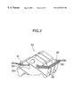
- FIG. 2 is a perspective view of a part of a metal belt.
- FIG. 3 is an illustration for explaining the tensile stress which is applied to a metal ring.
- FIG. 4 is an illustration showing the balance between the forces applied to the metal ring.
- FIG. 5 is a graph illustrating the change in ⁇ T 1 / ⁇ T ALL relative to the ratio of the coefficients of friction.
- FIG. 6 is a perspective view of a part of the metal belt used for an experiment to determine the characteristics of the change in stress applied to the metal ring.
- FIGS. 7A-7E are graphs illustrating the change in stress applied to the metal rings determined by an experiment.
- FIG. 8 is a graph illustrating the ratio Ta (n) / Ta (all) of the tension difference Ta (n) between the two chord parts of the metal ring of the outermost layer relative to the tension difference Ta (all) between the two chord parts of the metal ring assembly.
- FIG. 9 is a graph illustrating the ratio Tm (n) / Tm (all) of the sum Tm (n) of the tensions of the two chord parts of the metal ring of the outermost layer relative to the sum Tm (all) of the tensions of the two chord parts of the metal ring assembly.
- FIGS. 10A-10B are an illustrations for explaining the shapes in the free state and the engaged state of a metal ring.
- FIG. 11 is a graph illustrating the distribution of tensile stress applied to the metal ring of the innermost layer and the other metal rings.
- FIG. 12 is a graph illustrating the distribution of flexural stress applied to the metal ring of the innermost layer and the other metal rings.
- FIG. 13 is a graph illustrating the distribution of total stress applied to the metal ring of the innermost layer and the other metal rings.
- FIG. 14 is an illustration for explaining the calculation of the stress amplitude aa 1 applied to the metal ring of the innermost layer.
- FIG. 15 is a graph illustrating the change in stress amplitude ⁇ a 1 relative to t he thickness t 1 of the metal ring of the innermost layer.
- FIG. 16 is a graph illustrating the thickness t 1 at which the stress amplitude ⁇ a 1 coincides with the stress amplitude ⁇ a 1 and the thickness t 1 at which the stress amplitude ⁇ a 1 is a minimum.
- FIG. 17 is a graph illustrating the thickness ratio t 1 / t n at which the stress amplitude ⁇ a 1 coincides with the stress amplitude ⁇ a n and the thickness ratio t 1 /t n at which the stress amplitude ⁇ a 1 is a minimum.
- FIG. 1 shows an outline of the structure of a metal belt type continuously variable transmission T mounted in an automobile, in which an input shaft 3 connected to a crankshaft 1 of an engine E via a damper 2 is connected to a drive shaft 5 of the metal belt type continuously variable transmission T via a starting clutch 4 .
- a drive pulley 6 mounted on the drive shaft 5 comprises a stationary pulley 7 which is secured to the drive shaft 5 and a movable pulley 8 which is movable towards and away from the stationary pulley 7 .
- the movable pulley 8 is pushed towards the stationary pulley 7 by means of hydraulic pressure applied to an oil chamber 9 .
- a driven pulley 11 mounted on a driven shaft 10 positioned parallel to the drive shaft 5 , comprises a stationary pulley 12 which is secured to the driven shaft 10 and a movable pulley 13 which is movable towards and away from the stationary pulley 12 .
- the movable pulley 13 is pushed towards the stationary pulley 12 by means of hydraulic pressure applied to an oil chamber 14 .
- a metal belt 15 is formed by supporting a large number of metal elements 32 . . . on a pair of right and left metal ring assemblies 31 , 31 (see FIG. 2 ).
- the metal belt 15 is wrapped around both the drive pulley 6 and the driven pulley 11 .
- Each metal ring assembly 31 is formed by layering 12 sheets of metal rings 33 1 , 33 n . . .
- the driven shaft 10 carries a forward drive gear 16 and a reverse drive gear 17 in a relatively rotatable manner.
- the forward drive gear 16 and reverse drive gear 17 can be connected selectively to the driven shaft 10 by means of a selector 18 .
- An output shaft 19 is positioned parallel to the driven shaft 10 .
- a forward driven gear 20 is meshed with the forward drive gear 16
- a reverse driven gear 22 is meshed with the reverse drive gear 17 via a reverse idler gear 21 .
- the gears 20 and 22 are secured with the output shaft 19 .
- the rotation of the output shaft 19 is input to a differential 25 via a final drive gear 23 and a final driven gear 24 and transmitted therefrom to drive wheels W, W via right and left axles 26 , 26 .
- the drive power of the engine E is thus transmitted to the driven shaft 10 via the crankshaft 1 , the damper 2 , the input shaft 3 , the starting clutch 4 , the drive shaft 5 , the drive pulley 6 , the metal belt 15 and the driven pulley 11 .
- the drive power of the driven shaft 10 is transmitted to the output shaft 19 via the forward drive gear 16 and forward driven gear 20 , and the vehicle is thus driven forward.
- the reverse travel range the drive power of the driven shaft 10 is transmitted to the output shaft 19 via the reverse drive gear 17 , reverse idler gear 21 and reverse driven gear 22 , and thus the vehicle is driven backwards.
- the gear ratio can be adjusted continuously. That is to say, by increasing the hydraulic pressure applied to the oil chamber 14 of the driven pulley 11 relative to the hydraulic pressure applied to the oil chamber 9 of the drive pulley 6 , the groove width of the driven pulley 11 decreases thereby increasing the effective radius of the drive pulley 6 . Accordingly, the groove width of the drive pulley 6 increases thereby decreasing the effective radius of the driver pulley 11 .
- the gear ratio of the metal belt type continuously variable transmission T changes towards “LOW” in a continuous manner.
- the groove width of the drive pulley 6 decreases thereby increasing the effective radius of the driven pulley 11 .
- the groove width of the driven pulley 11 increases thereby decreasing the effective radius of the drive pulley 6 . Therefore, the gear ratio of the metal belt type continuously variable transmission T changes towards “TOP” in a continuous manner.
- FIG. 3 shows a state in which the vehicle is in the maximum travelling speed state (TOP state) and the effective radius of the drive pulley 6 becomes larger than the effective radius of the driven pulley 11 .
- the thickness of the metal belt 15 indicates the level of tensile stress applied to each metal ring assembly 31 resulting from the tension in the above-mentioned metal belt 15 .
- the above-mentioned stress is at a constant value of ⁇ T LOW
- the above-mentioned stress is at a constant value of ⁇ T HIGH
- the stress ⁇ T LOW in region A is smaller than the stress ⁇ T HIGH in region C.
- the stress increases from ⁇ T LOW to ⁇ T HIGH in going from the entry side to the exit side in the region (region B) where the metal belt 15 is wrapped around the drive pulley 6 .
- the stress decreases from ⁇ T HIGH to ⁇ T LOW in going from the entry side to the exit side in the region (region D) where the metal belt 15 is wrapped around the driven pulley 11 .
- the tension applied to the metal belt 15 is evenly shared by a pair of metal ring assemblies 31 , 31 .
- the tension applied to each metal ring assembly 31 is shared among 12 sheets of metal rings 33 1 , 33 n . . . which form the metal ring assembly 31 .
- the stresses applied to metal rings 33 n . . . (ring No. 2 to ring No. 12 ) of the second layer to the 12th layer from the inside, (excluding the metal ring 33 1 (ring No. 1 ) of the innermost layer which is in contact with the saddle surfaces 32 1 of the metal elements 32 ) are equal to each other.
- the stress applied to the above-mentioned metal ring 33 1 of the innermost layer has a value different from that for the above-mentioned stresses applied to the metal rings 33 of the second layer to the 12th layer. The reason therefor is explained below with reference to FIG. 4 .
- the metal ring assembly comprises three layers of metal rings.
- a perpendicular drag applied between ring No. 3 of the outermost layer and ring No. 2 inside ring No. 3 in the areas where the two rings are wrapped around a pulley is defined as N 3 .
- a perpendicular drag applied between ring No. 2 and ring No. 1 is defined as N 2 .
- a perpendicular drag applied between ring No. 1 and the saddle surface of the metal ring is defined as N 1 .
- the coefficient of friction between the metal ring and the metal element (hereinafter, termed ring-element coefficient of friction) is defined as ⁇ s.
- the loads on ring No. 1 , ring No. 2 and ring No. 3 are defined as F 1 , F 2 and F 3 respectively.
- the changes in tension applied to the metal rings of each layer ⁇ T 1 , ⁇ T 2 and ⁇ T 3 are given by equations (1) to (3) below.
- the ratio of ⁇ T 1 to ⁇ T ALL can be derived in the same manner using the above-mentioned equation (5).
- the ratio of the perpendicular drag N 1 to the perpendicular drag N 2 changes, and therefore the results of the calculation are different.
- Equation (6) illustrates that if N 2 / N 1 , which depends on the number of metal ring layers n included in a metal ring assembly, and the coefficient of friction ratio ⁇ , which is the ratio of the ring-element coefficient of friction ⁇ s to the ring-ring coefficient of friction ⁇ r, are determined, then the ratio of the change ⁇ T 1 in the tension applied to the metal ring of the innermost layer relative to the change ⁇ T ALL in the tension applied to the entire metal ring assembly can be determined.
- the coefficient of friction ratio ⁇ equals 1.0 and ⁇ T 1 / ⁇ T ALL becomes 0.08.
- the metal ring of the innermost layer receives the same change in tension as the remaining 11 , sheets of metal rings, that is to say, about 8% which is one 12th of the total change in tension ⁇ T ALL of the entire metal ring assembly.
- the actual coefficient of friction ratio ⁇ has a value larger than 1.0, and the change in tension ⁇ T 1 applied to the metal ring of the innermost layer becomes larger than the change in tension ⁇ T n applied to the other 11 sheets of metal rings.
- an actual metal ring assembly 31 comprises 12 sheets of metal rings 33 1 , 33 n . . . which are layered.
- a metal belt type continuously variable transmission T was operated using only one sheet of metal ring 33 instead of the above-mentioned metal ring assembly.
- a strain gauge 34 was attached to the radially outer surface of the metal ring 33 and the stress waveform applied to the metal ring 33 during operation was monitored.
- FIGS. 7A-7E shows the stress waveforms thus monitored and region A, region B, region C and region D correspond to region A, region B, region C and region D respectively shown in FIG. 3 .
- the stress in region A and region C is due to the tension applied to the metal ring 33 .
- the stress is low in region A which corresponds to the chord part on the relaxed side and is high in region C which corresponds to the chord part on the stretched side.
- the radius of curvature of the metal ring 33 in a free state is at infinity (i.e. straight line state).
- the difference between the tension in region C and the tension in region A here is examined, it is found that there is a distinct difference between a) when one sheet of the metal ring 33 is used (i.e. the stress applied to the metal ring 33 of the innermost layer which is in direct contact with the saddle surface 32 1 of the metal element 32 ) and b) when more than one sheet of the metal rings 33 are used (i.e. the stress applied to the metal rings of layers other than the innermost layer). That is to say, only the metal ring 33 of the innermost layer has a stress characteristic which is greatly different from the stress characteristic of the metal rings 33 of layers other than the innermost layer. As hereinafter described, it has been found that the difference in tension between region C and region A for the metal ring 33 of the innermost layer is twice that of the metal rings 33 of layers other than the innermost layer.
- the graph shown in FIG. 8 was obtained from the above-mentioned measurement results.
- the abscissa denotes the number of layered sheets of metal rings 33 and the ordinate denotes the proportion Ta (n) / Ta (all) of the difference in tension in the metal ring 33 of the outermost layer.
- the difference in tension of the metal ring 33 denotes the difference between the tension applied to the chord part on the stretched side and the tension applied to the chord part on the relaxed side.
- Ta (n) denotes the difference in tension for the metal ring 33 of the outermost layer and Ta (all) denotes the total difference in tension for all the metal rings 33 that are layered.
- Ta (all) is the sum of the differences in tension applied to the metal rings 33 and Ta (n) is the difference in tension applied to the metal ring 33 of the outermost layer (second layer)
- Ta (n) / Ta (all) should be 0.5, but actually Ta (n) / Ta (all) equals 0.33.
- the difference in tension applied to the metal ring 33 of the innermost layer is twice the difference in tension applied to the other metal rings 33 .
- the proportion of the difference in tension in the metal ring 33 of the innermost layer is two sixths of the total change in tension, and the other 4 sheets of the metal rings 33 have one sixths each of the total change in tension.
- the metal ring 33 1 of the innermost layer would have 2 / 13 of the total change in tension and the remaining 11 sheets of metal rings 33 n . . . would have 1 /13 each of the total change in tension.
- the graph shown in FIG. 9 was obtained from the above-mentioned measurement results.
- the abscissa denotes the number of layered sheets of the metal rings 33
- the ordinate denotes the proportion Tm (n) / Tm (all) of the sum of the tensions in the metal ring 33 of the outermost layer.
- the sum of the tensions applied to a metal ring 33 here denotes the sum of the tension in the chord part on the stretched side and tension in the chord part on the relaxed side.
- Tm (n) is the sum of the tensions applied to the metal ring 33 of the outermost layer
- Tm (all) is the sum of the tensions applied to all the metal rings 33 that are layered.
- each metal ring 33 has 1 / 5 of the sum of the tensions applied to the metal ring assembly 31 and it can be surmised that when the number of layers of metal rings 33 1 , 33 n . . . is 12, each metal ring 33 1 , 33 n . . . has 1 /12 of the sum of the tensions applied to the metal ring assembly 31 . That is to say, it can be surmised that the distribution of the sum of the tensions applied to the metal ring assembly 31 is uniform in the radial direction (thickness direction).
- the graph in FIG. 11 shows the change in tensile stress applied to the metal ring 33 1 of the innermost layer of the present embodiment and the change in tensile stress applied to the other 11 sheets of metal rings 33 n . . . when the vehicle is in the maximum travelling speed state as explained in FIG. 3 .
- the solid and broken lines in the above figure correspond to the case where the metal ring 33 1 of the innermost layer has the same thickness as that of the other metal rings 33 n . . .
- the solid line denotes the change in tensile stress applied to the metal ring 33 1 of the innermost layer
- the broken line denotes the change in tensile stress applied to the 11 sheets of metal rings 33 n . . . of layers other than the innermost layer.
- the change in tension (i.e. change in stress) applied to the metal ring 33 1 of the innermost layer is twice the change in tension (i.e. change in stress) applied to the other metal rings 33 1 . . .
- the single-dotted broken line and the double-dotted broken line in FIG. 11 denote a case (after improvement) where the thickness t 1 of the metal ring 33 1 of the innermost layer is different from the thickness t n of the other metal rings 33 n . . .
- the single-dotted broken line denotes the change in tensile stress applied to the metal ring 33 1 of the innermost layer
- the double-dotted broken line denotes the change in tensile stress applied to the 11 sheets of metal rings 33 n . . . of layers other than the innermost layer.
- This change in the stress characteristics resulting from the difference in thickness t 1 of the metal ring 33 1 of the innermost layer is based on the tension sharing characteristics described in FIG. 8 and FIG. 9 .
- a tensile stress and a compressive stress resulting from the flexure of the metal rings 33 1 , 33 n . . . are also applied to the metal rings 33 1 , 33 n . . .
- the metal rings 33 1 , 33 n . . . in the free state are in a circular form, but the metal rings 33 1 , 33 n . . . in an engaged state change into a shape having the above-mentioned regions A to D.
- the radius of curvature which is D / 2 in the free state increases to ⁇ in the chord part on the relaxed side (region A) and the chord part on the stretched side (region C).
- region B where the belt is wrapped around a drive pulley having a large diameter
- the radius of curvature which is D / 2 in the free state decreases to R DR .
- region D where the belt is wrapped around a driven pulley having a small diameter
- the radius of curvature which is D / 2 in the free state decreases to R DN .
- the graph shown in FIG. 12 illustrates the flexural stress applied to each of the radially outer surfaces of the 12 sheets of metal rings 33 1 , 33 n . . . when the vehicle is at a maximum travelling speed state described in FIG. 3 .
- the solid line denotes the case where the thicknesses t 1 , t n of the metal rings 33 1 , 33 n are identical.
- a constant compressive flexural stress is applied to the radially outer surfaces of each metal ring 33 1 , 33 n . . . in the two chord parts (region A and region C).
- a comparatively small stretching flexural stress is applied thereto in region B where they are wrapped around the drive pulley having a larger radius of curvature.
- Comparatively large stretching flexural stress is applied thereto in region D where they are wrapped around the driven pulley having a smaller radius of curvature.
- the single-dotted broken line denotes the flexural stress applied to the radially outer surface of the metal ring 33 1 of the innermost layer when the thickness t 1 of the above-mentioned metal ring 33 1 of the innermost layer is different from the thickness t n of the other metal rings 33 n . . . (after improvement). It has been found that the flexural stress characteristics change according to the change in thickness t 1 .
- the graph shown in FIG. 13 illustrates the sums of a) the stress resulting from the tension applied to the metal rings 33 1 , 33 n . . . shown in FIG. 11 and b) the stress applied to the radially outer surfaces of the above-mentioned rings 33 1 , 33 n . . . resulting from the flexure of the metal rings 33 1 , 33 n . . . shown in FIG. 12 .
- the solid line and the single-dotted broken line denote changes in the total stress applied to the radially outer surface of the metal ring 33 1 of the innermost layer before and after improvement.
- the broken line and the double-dotted broken line denote changes in the total stress applied to the radially outer surface of the other metal rings 33 n . . . before and after improvement.
- the stress amplitude ⁇ a 1 applied to the metal ring 33 1 of the innermost layer is smaller than the stress amplitude Gan applied to the other metal rings 33 n . . .
- the durability of the metal ring 33 1 of the innermost layer can be enhanced and thus the life span of the metal ring assembly 31 can be increased.
- a means to set the thickness t 1 of the metal ring 33 1 of the innermost layer at an appropriate level is explained below.
- the stress amplitude ⁇ a 1 applied to the radially outer surface of the metal ring 33 1 of the innermost layer is given by equation (11) below.
- the stress amplitude ⁇ a n applied to the radially outer surfaces of the other metal rings 33 n . . . is given by equation (12) below.
- the average stresses ⁇ m 1 , ⁇ m n . . . applied to the outer surfaces of the metal ring 33 1 of the innermost layer and the other metal rings 33 n . . . are given by equation (13) and equation (14) respectively.
- E denotes the Young's modulus
- D denotes the diameter of metal rings 33 1 , 33 n . . . in the free state
- d o denotes the diameter of the pulley around which metal rings 33 1 , 33 n . . . are wrapped.
- the graph shown in FIG. 15 illustrates the results of calculating the relationship between the thickness t 1 of the metal ring 33 1 of the innermost layer (abscissa) and the stress amplitude ⁇ a 1 applied to the metal ring 33 1 of the innermost layer (ordinate) under high speed durability conditions based on the above-mentioned equations (7) to (12).
- the specifications for the operating conditions of the metal belt type continuously variable transmission T are given in Table 2. By applying these specifications to an equation disclosed in Japanese Patent Application Laid-Open No. 10-89429, the tension T1 in the chord part on the stretched side of the metal ring assembly 31 and the tension T2 in the chord part on the relaxed side thereof are calculated.
- the stress amplitude ⁇ a 1 applied to the metal ring 33 1 of the innermost layer becomes a minimum value of 20.72 kgf / mm 2 (see Table 3). That is to say, if the thickness of the metal ring 33 1 of the innermost layer is set so as to satisfy the relationship 0.042 mm ⁇ t 1 ⁇ 0.161 mm, the stress amplitude ⁇ a 1 applied to the above-mentioned metal ring 33 1 of the innermost layer can be made smaller than the stress amplitude ⁇ a n applied to the other metal rings 33 n . Thus, the metal ring 33 1 of the innermost layer can be prevented from fracturing at an early stage which degraded the life span of the entire metal ring assembly 31 .
- Table 3 also gives the average stress ⁇ m 1 applied to the metal ring 33 1 of the innermost layer and average stress ⁇ m n applied to the other metal rings 33 n . . . which are calculated based on the above-mentioned equations (13) and (14).
- the maximum average stress ⁇ m 1 applied to the metal ring 33 1 of the innermost layer is reduced to 21.46 kgf / mm 2
- the maximum average stress ⁇ m n applied to the other metal rings 33 n is also reduced to 23.00 kgf / mm 2 . Therefore, the average stresses d ⁇ m 1 , ⁇ m n applied both to the innermost metal ring 33 1 and to the other metal rings 33 n . . . do not increase greatly even when the thickness t 1 of the metal ring 33 1 of the innermost layer is changed.
- FIG. 16 shows the thickness t 1 (indicated by ⁇ ) of the metal ring 33 1 of the innermost layer at which the stress amplitude ⁇ a 1 coincides with the stress ⁇ a n and the thickness t 1 (indicated by ⁇ ) of the metal ring 33 1 of the innermost layer at which the stress amplitude ⁇ a 1 becomes a minimum value when the input horsepower to the metal belt type continuously variable transmission T is varied. That is to say, when the thickness t 1 of the metal ring 33 1 of the innermost layer is in the hatched region, the stress amplitude ⁇ a 1 can be reduced to can or less, thus increasing the life span of the metal ring assembly 31 . In particular, if the thickness t 1 of the metal ring 33 1 of the innermost layer is set at 0.113 mm, the life span of the metal ring assembly 31 can be increased in the entire region up to the maximum input horsepower value of 312 PS.
- the total stress amplitude applied to the metal ring of the innermost layer can be reduced so as to be not more than the total stress amplitude applied to the other metal rings. Therefore, the durability of the metal ring of the innermost layer, which is used under the most severe conditions, can be made higher than the durability of the other metal rings in order to increase the life span of the entire metal ring assembly.
- the thickness of the metal ring of the innermost layer can be set appropriately.
- the thickness of the metal ring of the innermost layer is set so that at a maximum horsepower operating state the stress amplitude applied to the aforementioned metal ring of the innermost layer coincides with the stress amplitude applied to the metal rings of layers other than the innermost layer, the durability of the metal ring of the innermost layer can be increased to the highest level under all operating conditions including the most severe operating conditions at the maximum horsepower operating state.
- the appropriate thickness t 1 of the metal ring 33 1 of the innermost layer was determined above based on the stress amplitudes ⁇ a 1 , ⁇ a n applied to the radially outer surfaces of the metal rings 33 1 , 33 n . . . an appropriate thickness may be determined based on the stress amplitudes applied to the radially inner surfaces since the forces applied to the metal rings are distributed evenly in the radial direction.
Landscapes
- Engineering & Computer Science (AREA)
- General Engineering & Computer Science (AREA)
- Mechanical Engineering (AREA)
- Transmissions By Endless Flexible Members (AREA)
Abstract
The durability of the entire metal ring assembly is enhanced by increasing the wear life of the radially inner surface of the metal ring of the innermost layer which is the layer which is most easily fractured. A belt for a continuously variable transmission is formed by supporting a large number of metal elements on a metal ring assembly wherein multiple sheets of endless metal rings are layered. The thickness of the metal ring of the innermost layer is different from the thickness of the metal rings of layers other than the innermost layer. The thickness of the metal ring of the innermost layer is set so that the stress amplitude applied to the radially outer surface of the metal ring of the innermost layer is not more than the stress amplitude applied to the radially outer surfaces of the metal rings of layers other than the innermost layer. By setting the thickness of the metal ring of the innermost layer at 0.042 mm to 0.161 mm when the thickness of the metal rings of layers other than the innermost layer is 0.185 mm, the stress amplitude sigmaa1 applied to the metal ring of the innermost layer becomes lower than the stress amplitude sigmaan of 25.65 kgf/- mm2 applied to the other metal rings. Thus the durability of the metal ring of the innermost layer can be enhanced to increase the life span of the entire metal ring assembly.
Description
1. Field of the Invention
The present invention relates to belts for a continuously variable transmission. The belts are formed by supporting a large number of metal elements on a metal ring assembly wherein multiple sheets of endless metal rings are layered.
2. Description of the Prior Art
When a metal belt of a continuously variable transmission is gripped by V-faces of its drive pulley and driven pulley, tension is generated in the metal belt. Since the tension varies depending on the drive power and the braking power produced by the two pulleys, the tensile stress applied to each metal ring changes periodically with the circulation of the metal belt. Moreover, since the circulating metal belt is bent where it wraps around the pulleys and is stretched in the chord parts between the pulleys, the flexural stress applied to each metal ring also varies periodically. As a result, the total stress (the sum of the above-mentioned tensile stress and the above-mentioned flexural stress) applied to each metal ring varies periodically during one revolution of the metal belt.
Japanese Patent Application Laid-Open No. 57-57938 has therefore proposed that by applying a) a residual compressive stress to the radially outer surface of each metal ring of the metal ring assembly and b) a residual stretching stress to the radially inner surface, the median of the stress amplitude (stress median) applied to each metal ring, which varies periodically, is made as close to 0 as possible thereby attempting to extend the wear life of the metal belt.
The above-mentioned conventional arrangement does not differentiate between the metal ring of the innermost layer from the other metal rings. A residual compressive stress is applied to the radially outer surfaces of all the metal rings, and a residual stretching stress is applied to the radially inner surfaces. Therefore, the durability of the entire metal belt is restricted by the durability of the metal ring of the innermost layer which is used under severe conditions such as those resulting from large changes in tension. Moreover, the processing needed in order to apply the residual compressive stress and the residual stretching stress to the radially outer and inner surfaces of each metal ring becomes a principal cause for increased cost.
The present invention has been conducted in view of the above-mentioned circumstances, and it is an objective of the present invention to increase the durability of the entire metal ring assembly by prolonging the wear life of the metal ring of the innermost layer which is the one which is most easily fractured.
The metal ring of the innermost layer of such a metal ring assembly is in direct contact with the saddle surfaces of the metal elements, whereas the radially inner surfaces of the other metal rings are in direct contact with the radially outer surfaces of the other metal rings. Therefore, the coefficients of friction of the two contact areas are different from each other. More specifically, the coefficient of friction of the radially inner surface of the metal ring of the innermost layer, which is in direct contact with the saddle surfaces of the metal elements, has actually been measured and found to be larger than the coefficient of friction of the radially inner surfaces of the other metal rings. As a result, as is described in detail in the embodiment below, the change in tension applied to the metal ring of the innermost layer (the difference between the maximum tension and the minimum tension in one cycle) becomes larger than the changes in tension applied to the other metal rings.
In order to achieve the above-mentioned objective, the present invention is a belt for a continuously variable transmission formed by supporting a large number of metal elements on a metal ring assembly wherein multiple sheets of endless metal rings are layered. The thickness of the metal ring of the innermost layer is different from the thickness of the metal rings of layers other than the innermost layer. The thickness of the metal ring of the innermost layer is set so that the stress amplitude applied to the metal ring of the innermost layer is not more than the stress amplitude applied to the metal rings of layers other than the innermost layer.
The invention is further characterized in that the thickness of the metal ring of the innermost layer is set so that the stress amplitude applied to the metal ring of the innermost layer is not more than the stress amplitude applied to the metal rings of layers other than the innermost layer provided that the difference between the tension applied to the chord part on the stretched side and the tension applied to the chord part on the relaxed side of the metal ring of the innermost layer is different from a difference between tension of the chord part on the stretched side and the tension of the chord part on the relaxed side of the metal rings of layers other than the innermost layer. The sum of the tension of the chord part on the stretched side and the tension of the chord part on the relaxed side of the metal ring assembly is distributed evenly in the radial direction of the metal ring assembly.
The invention is further characterized in that the thickness of the metal ring of the innermost layer is set so that at a maximum horsepower operating state, the stress amplitude applied to the metal ring of the innermost layer coincides with the stress amplitude applied to the metal rings of layers other than the innermost layer.
Since the coefficient of friction of the radially inner surface of the metal ring of the innermost layer, which is in contact with the saddle surfaces of the metal elements, is larger than the coefficient of friction between the metal rings which are in contact with each other, the change in tension applied to the metal ring of the innermost layer (i.e., a difference in tension between the chord part on the stretched side and the chord part on the relaxed side) becomes larger than the change in tension applied to the other metal rings, and the stress amplitude applied to the metal ring of the innermost layer accompanying the change in tension becomes larger than the stress amplitude applied to the other metal rings. As a result, if the thickness of the metal ring of the innermost layer is set at a value equal to the thickness of the other metal rings, when considering the total stress which comprises the tensile stress applied to the metal rings and the flexural stress applied to the metal rings , the total stress amplitude applied to the metal ring of the innermost layer becomes larger than the total stress amplitude applied to the other metal rings. Thus the durability of the metal ring of the innermost layer is restricted.
By differentiating the thickness of the metal ring of the innermost layer, which is used under the most severe conditions, from the thickness of the other metal rings so as to differentiate the flexural stress applied to the metal ring of the innermost layer from the flexural stress applied to the other metal rings, the total stress amplitude applied to the metal ring of the innermost layer can therefore be reduced so as to be not more than the total stress amplitude applied to the other metal rings. That is to say, if the thickness of the metal ring of the innermost layer is set so that the total stress amplitude applied to the metal ring of the innermost layer is not more than the total stress amplitude applied to the other metal rings, the durability of the metal ring of the innermost layer, which is used under the most severe conditions, can be made higher than the durability of the other metal rings to increase the life span of the entire metal ring assembly.
In particular, if the difference between the tension applied to the chord part on the stretched side and the tension applied to the chord part on the relaxed side of the metal ring of the innermost layer is assumed to be different from a difference between the tension of the chord part on the stretched side and the tension of the chord part on the relaxed side of the metal rings of layers other than the innermost layer and the sum of the tension of the chord part on the stretched side and the tension of the chord part on the relaxed side of the metal ring assembly is assumed to be distributed evenly in the radial direction of the metal ring assembly, the thickness of the metal ring of the innermost layer can be set appropriately.
Furthermore, if the thickness of the metal ring of the innermost layer is set so that at a maximum horsepower operating state the stress amplitude applied to the metal ring of the innermost layer coincides with the stress amplitude applied to the metal rings of layers other than the innermost layer, the durability of the metal ring of the innermost layer can be increased to the highest level under all operating conditions including the most severe operating conditions at the maximum horsepower operating state.
The present invention is described below by reference to the Embodiment of the present invention shown in the attached drawings.
FIG. 1 to FIG. 17 illustrate one embodiment of the present invention.
FIG. 1 is an outline diagram of the power transmission system of a vehicle on which a continuously variable transmission is mounted.
FIG. 2 is a perspective view of a part of a metal belt.
FIG. 3 is an illustration for explaining the tensile stress which is applied to a metal ring.
FIG. 4 is an illustration showing the balance between the forces applied to the metal ring.
FIG. 5 is a graph illustrating the change in ΔT1/ ΔTALL relative to the ratio of the coefficients of friction.
FIG. 6 is a perspective view of a part of the metal belt used for an experiment to determine the characteristics of the change in stress applied to the metal ring.
FIGS. 7A-7E are graphs illustrating the change in stress applied to the metal rings determined by an experiment.
FIG. 8 is a graph illustrating the ratio Ta(n)/ Ta(all) of the tension difference Ta(n) between the two chord parts of the metal ring of the outermost layer relative to the tension difference Ta(all) between the two chord parts of the metal ring assembly.
FIG. 9 is a graph illustrating the ratio Tm(n)/ Tm(all) of the sum Tm(n) of the tensions of the two chord parts of the metal ring of the outermost layer relative to the sum Tm(all) of the tensions of the two chord parts of the metal ring assembly.
FIGS. 10A-10B are an illustrations for explaining the shapes in the free state and the engaged state of a metal ring.
FIG. 11 is a graph illustrating the distribution of tensile stress applied to the metal ring of the innermost layer and the other metal rings.
FIG. 12 is a graph illustrating the distribution of flexural stress applied to the metal ring of the innermost layer and the other metal rings.
FIG. 13 is a graph illustrating the distribution of total stress applied to the metal ring of the innermost layer and the other metal rings.
FIG. 14 is an illustration for explaining the calculation of the stress amplitude aa1 applied to the metal ring of the innermost layer.
FIG. 15 is a graph illustrating the change in stress amplitude σa1 relative to t he thickness t1 of the metal ring of the innermost layer.
FIG. 16 is a graph illustrating the thickness t1 at which the stress amplitude σa1 coincides with the stress amplitude σa1 and the thickness t1 at which the stress amplitude σa1 is a minimum.
FIG. 17 is a graph illustrating the thickness ratio t1/ tn at which the stress amplitude σa1 coincides with the stress amplitude σan and the thickness ratio t1/tn at which the stress amplitude σa1 is a minimum.
FIG. 1 shows an outline of the structure of a metal belt type continuously variable transmission T mounted in an automobile, in which an input shaft 3 connected to a crankshaft 1 of an engine E via a damper 2 is connected to a drive shaft 5 of the metal belt type continuously variable transmission T via a starting clutch 4. A drive pulley 6 mounted on the drive shaft 5 comprises a stationary pulley 7 which is secured to the drive shaft 5 and a movable pulley 8 which is movable towards and away from the stationary pulley 7. The movable pulley 8 is pushed towards the stationary pulley 7 by means of hydraulic pressure applied to an oil chamber 9.
A driven pulley 11, mounted on a driven shaft 10 positioned parallel to the drive shaft 5, comprises a stationary pulley 12 which is secured to the driven shaft 10 and a movable pulley 13 which is movable towards and away from the stationary pulley 12. The movable pulley 13 is pushed towards the stationary pulley 12 by means of hydraulic pressure applied to an oil chamber 14. A metal belt 15 is formed by supporting a large number of metal elements 32 . . . on a pair of right and left metal ring assemblies 31, 31 (see FIG. 2). The metal belt 15 is wrapped around both the drive pulley 6 and the driven pulley 11. Each metal ring assembly 31 is formed by layering 12 sheets of metal rings 33 1, 33 n . . .
The driven shaft 10 carries a forward drive gear 16 and a reverse drive gear 17 in a relatively rotatable manner. The forward drive gear 16 and reverse drive gear 17 can be connected selectively to the driven shaft 10 by means of a selector 18. An output shaft 19 is positioned parallel to the driven shaft 10. A forward driven gear 20 is meshed with the forward drive gear 16, and a reverse driven gear 22 is meshed with the reverse drive gear 17 via a reverse idler gear 21. The gears 20 and 22 are secured with the output shaft 19.
The rotation of the output shaft 19 is input to a differential 25 via a final drive gear 23 and a final driven gear 24 and transmitted therefrom to drive wheels W, W via right and left axles 26, 26.
The drive power of the engine E is thus transmitted to the driven shaft 10 via the crankshaft 1, the damper 2, the input shaft 3, the starting clutch 4, the drive shaft 5, the drive pulley 6, the metal belt 15 and the driven pulley 11. When the forward travel range is selected, the drive power of the driven shaft 10 is transmitted to the output shaft 19 via the forward drive gear 16 and forward driven gear 20, and the vehicle is thus driven forward. When the reverse travel range is selected, the drive power of the driven shaft 10 is transmitted to the output shaft 19 via the reverse drive gear 17, reverse idler gear 21 and reverse driven gear 22, and thus the vehicle is driven backwards.
At this stage, by controlling the hydraulic pressures applied to the oil chamber 9 of the drive pulley 6 and the oil chamber 14 of the driven pulley 11 of the metal belt type continuously variable transmission T by means of a hydraulic control unit U2 operated by commands from an electronic control unit U1, the gear ratio can be adjusted continuously. That is to say, by increasing the hydraulic pressure applied to the oil chamber 14 of the driven pulley 11 relative to the hydraulic pressure applied to the oil chamber 9 of the drive pulley 6, the groove width of the driven pulley 11 decreases thereby increasing the effective radius of the drive pulley 6. Accordingly, the groove width of the drive pulley 6 increases thereby decreasing the effective radius of the driver pulley 11. Therefore the gear ratio of the metal belt type continuously variable transmission T changes towards “LOW” in a continuous manner. On the other hand, by increasing the hydraulic pressure applied to the oil chamber 9 of the drive pulley 6 relative to the hydraulic pressure applied to the oil chamber 14 of the driven pulley 11, the groove width of the drive pulley 6 decreases thereby increasing the effective radius of the driven pulley 11. Accordingly, the groove width of the driven pulley 11 increases thereby decreasing the effective radius of the drive pulley 6. Therefore, the gear ratio of the metal belt type continuously variable transmission T changes towards “TOP” in a continuous manner.
FIG. 3 shows a state in which the vehicle is in the maximum travelling speed state (TOP state) and the effective radius of the drive pulley 6 becomes larger than the effective radius of the driven pulley 11. The thickness of the metal belt 15 indicates the level of tensile stress applied to each metal ring assembly 31 resulting from the tension in the above-mentioned metal belt 15. In the chord part on the relaxed side (region A) where the metal belt 15 returns from the driven pulley 11 to drive pulley 6 the above-mentioned stress is at a constant value of σTLOW In the chord part on the stretched side (region C), where the metal belt 15 is fed from the drive pulley 6 to the driven pulley 11, the above-mentioned stress is at a constant value of σTHIGH. The stress σTLOW in region A is smaller than the stress σTHIGH in region C. The stress increases from σTLOW to σTHIGH in going from the entry side to the exit side in the region (region B) where the metal belt 15 is wrapped around the drive pulley 6. The stress decreases from σTHIGH to σTLOW in going from the entry side to the exit side in the region (region D) where the metal belt 15 is wrapped around the driven pulley 11.
The tension applied to the metal belt 15 is evenly shared by a pair of metal ring assemblies 31, 31. The tension applied to each metal ring assembly 31 is shared among 12 sheets of metal rings 33 1, 33 n . . . which form the metal ring assembly 31. Here, the stresses applied to metal rings 33 n . . . (ring No. 2 to ring No. 12) of the second layer to the 12th layer from the inside, (excluding the metal ring 33 1 (ring No. 1) of the innermost layer which is in contact with the saddle surfaces 32 1 of the metal elements 32) are equal to each other. However, the stress applied to the above-mentioned metal ring 33 1 of the innermost layer has a value different from that for the above-mentioned stresses applied to the metal rings 33 of the second layer to the 12th layer. The reason therefor is explained below with reference to FIG. 4.
As a simple model, a case is considered where the metal ring assembly comprises three layers of metal rings. A perpendicular drag applied between ring No. 3 of the outermost layer and ring No. 2 inside ring No. 3 in the areas where the two rings are wrapped around a pulley is defined as N3. A perpendicular drag applied between ring No. 2 and ring No. 1 is defined as N2. A perpendicular drag applied between ring No. 1 and the saddle surface of the metal ring is defined as N1. When the coefficient of friction between metal rings which are in contact with each other (hereinafter, termed ring-ring coefficient of friction) is defined as μr. The coefficient of friction between the metal ring and the metal element (hereinafter, termed ring-element coefficient of friction) is defined as μs. The loads on ring No. 1, ring No. 2 and ring No. 3 are defined as F1, F2 and F3 respectively. The changes in tension applied to the metal rings of each layer ΔT1, ΔT2 and ΔT3 are given by equations (1) to (3) below.
The total change ΔTALL in the tensions applied to the metal rings of each layer ΔT1, ΔT2 and ΔT3 is given by 
and the ratio of ΔT1 to ΔTALL can be derived from the above-mentioned equation (3) and equation (4). 
Here, even when considering a case where the number of metal ring layers is extended to n, the ratio of ΔT1 to ΔTALL can be derived in the same manner using the above-mentioned equation (5). However, as the number of metal ring layers n changes, the ratio of the perpendicular drag N1 to the perpendicular drag N2 changes, and therefore the results of the calculation are different.
If a coefficient of friction ratio which is the ratio of the ring-element coefficient of friction μs to the ring-ring coefficient of friction μs is defined here as ξ(=μs /μr) the above-mentioned equation (5) can be transformed as follows.
The above-mentioned equation (6) illustrates that if N2/ N1, which depends on the number of metal ring layers n included in a metal ring assembly, and the coefficient of friction ratio ξ, which is the ratio of the ring-element coefficient of friction μs to the ring-ring coefficient of friction μr, are determined, then the ratio of the change ΔT1 in the tension applied to the metal ring of the innermost layer relative to the change ΔTALL in the tension applied to the entire metal ring assembly can be determined.
The graph in FIG. 5 shows the results of calculating ΔT1/ΔTALL for various coefficient of friction ratios ξwhen the metal ring assembly comprises 12 sheets of metal rings (i.e. n =12). The ratio of the perpendicular drags N1, N2 is set so as to be in a predetermined relationship, that is to say, it satisfies the relationship N2/N1=(n−1)/n. From previous experience and the experimental results, if the metal ring of the innermost layer is the same as the other metal rings, since the ring-element coefficient of friction μs is larger than the. ring-ring coefficient of friction μr, the coefficient of friction ratio ξ(=μs/μr) becomes greater than 1.0.
If the ring-ring coefficient of friction μr is made to coincide with the ring-element coefficient of friction μs in FIG. 5, the coefficient of friction ratio ξequals 1.0 and ΔT1/ΔTALL becomes 0.08. Thus, the metal ring of the innermost layer receives the same change in tension as the remaining 11, sheets of metal rings, that is to say, about 8% which is one 12th of the total change in tension ΔTALL of the entire metal ring assembly. However, the actual coefficient of friction ratio ξhas a value larger than 1.0, and the change in tension ΔT1 applied to the metal ring of the innermost layer becomes larger than the change in tension ΔTn applied to the other 11 sheets of metal rings.
Therefore, the relationship between the change in tension ΔT1 applied to the single sheet of metal ring of the innermost layer and the change in tension ΔTn applied to the other 11 sheets of metal rings has been examined by the means described below. As shown in FIG. 2, an actual metal ring assembly 31 comprises 12 sheets of metal rings 33 1, 33 n . . . which are layered. However, as shown in FIG. 6 a metal belt type continuously variable transmission T was operated using only one sheet of metal ring 33 instead of the above-mentioned metal ring assembly. Here, a strain gauge 34 was attached to the radially outer surface of the metal ring 33 and the stress waveform applied to the metal ring 33 during operation was monitored. Next, two sheets of metal rings 33 were superimposed and installed, and the stress waveform applied to the metal ring 33 of the outermost layer was monitored by attaching the strain gauge 34 to the radially outer surface of the above-mentioned metal ring 33 of the outermost layer. The above-mentioned procedure was repeated, increasing the number of sheets of the metal rings 33 having an identical thickness one by one up to 5 sheets.
FIGS. 7A-7E shows the stress waveforms thus monitored and region A, region B, region C and region D correspond to region A, region B, region C and region D respectively shown in FIG. 3. The stress in region A and region C is due to the tension applied to the metal ring 33. The stress is low in region A which corresponds to the chord part on the relaxed side and is high in region C which corresponds to the chord part on the stretched side. In order that only tensile stress and no flexural stress is generated in region A and region C which correspond to the chord parts of the metal ring 33, the radius of curvature of the metal ring 33 in a free state is at infinity (i.e. straight line state).
If the difference between the tension in region C and the tension in region A here is examined, it is found that there is a distinct difference between a) when one sheet of the metal ring 33 is used (i.e. the stress applied to the metal ring 33 of the innermost layer which is in direct contact with the saddle surface 32 1 of the metal element 32) and b) when more than one sheet of the metal rings 33 are used (i.e. the stress applied to the metal rings of layers other than the innermost layer). That is to say, only the metal ring 33 of the innermost layer has a stress characteristic which is greatly different from the stress characteristic of the metal rings 33 of layers other than the innermost layer. As hereinafter described, it has been found that the difference in tension between region C and region A for the metal ring 33 of the innermost layer is twice that of the metal rings 33 of layers other than the innermost layer.
The graph shown in FIG. 8 was obtained from the above-mentioned measurement results. The abscissa denotes the number of layered sheets of metal rings 33 and the ordinate denotes the proportion Ta(n)/ Ta(all) of the difference in tension in the metal ring 33 of the outermost layer. The difference in tension of the metal ring 33 denotes the difference between the tension applied to the chord part on the stretched side and the tension applied to the chord part on the relaxed side. Ta(n) denotes the difference in tension for the metal ring 33 of the outermost layer and Ta(all) denotes the total difference in tension for all the metal rings 33 that are layered. When the number of layered sheets of the metal rings 33 is one, Ta(n)=Ta(all) and thus Ta(n)/ Ta(all)=1.0. When the number of layered sheets of the metal rings 33 is two, since Ta(all) is the sum of the differences in tension applied to the metal rings 33 and Ta(n) is the difference in tension applied to the metal ring 33 of the outermost layer (second layer), if the tensions applied to two sheets of the metal rings 33 are identical, Ta(n)/ Ta(all) should be 0.5, but actually Ta(n)/ Ta(all) equals 0.33. Similarly, when the number of layered sheets of the metal rings 33 is 3, 4 and 5, Ta(n)/ Ta(all)=0.25, Ta(n)/ Ta(all)=0.20 and Ta(n)/ Ta(all)=0,17 respectively.
From the results above it has been found that the difference in tension applied to the metal ring 33 of the innermost layer is twice the difference in tension applied to the other metal rings 33. For example, when the number of layered sheets of the metal rings 33 is 5 sheets, the proportion of the difference in tension in the metal ring 33 of the innermost layer is two sixths of the total change in tension, and the other 4 sheets of the metal rings 33 have one sixths each of the total change in tension.
Therefore, as in the embodiment, when 12 sheets of metal rings 33 1, 33 n . . . are layered, it can be surmised that the metal ring 33 1 of the innermost layer would have 2 / 13 of the total change in tension and the remaining 11 sheets of metal rings 33 n . . . would have 1 /13 each of the total change in tension.
The graph shown in FIG. 9 was obtained from the above-mentioned measurement results. The abscissa denotes the number of layered sheets of the metal rings 33, and the ordinate denotes the proportion Tm(n)/ Tm(all) of the sum of the tensions in the metal ring 33 of the outermost layer. The sum of the tensions applied to a metal ring 33 here denotes the sum of the tension in the chord part on the stretched side and tension in the chord part on the relaxed side. Tm(n) is the sum of the tensions applied to the metal ring 33 of the outermost layer and Tm(all) is the sum of the tensions applied to all the metal rings 33 that are layered. When the number of layered sheets of the metal ring 33 is one, Tm(n)=Tm(all) and Tm(n)/ Tm(all)=1.0. When the number of layered sheets of the metal rings 33 is 2, 3, 4 and 5, Tm(n)/Tm(all)=0.50, Tm(n)/Tm(all)=0.33, Tm(n)/Tm(all)=0.25 and Tm(n)/Tm(all)=0.20 respectively.
It can be found from the results above that when the number of layers of the metal rings 33 is 5, each metal ring 33 has 1 / 5 of the sum of the tensions applied to the metal ring assembly 31 and it can be surmised that when the number of layers of metal rings 33 1, 33 n . . . is 12, each metal ring 33 1, 33 n . . . has 1 /12 of the sum of the tensions applied to the metal ring assembly 31. That is to say, it can be surmised that the distribution of the sum of the tensions applied to the metal ring assembly 31 is uniform in the radial direction (thickness direction).
The graph in FIG. 11 shows the change in tensile stress applied to the metal ring 33 1 of the innermost layer of the present embodiment and the change in tensile stress applied to the other 11 sheets of metal rings 33 n . . . when the vehicle is in the maximum travelling speed state as explained in FIG. 3. The solid and broken lines in the above figure correspond to the case where the metal ring 33 1 of the innermost layer has the same thickness as that of the other metal rings 33 n . . . The solid line denotes the change in tensile stress applied to the metal ring 33 1 of the innermost layer, and the broken line denotes the change in tensile stress applied to the 11 sheets of metal rings 33 n . . . of layers other than the innermost layer. Due to the above-mentioned disparity between the ring-element coefficient of friction μs and the ring-ring coefficient of friction μr, the change in tension (i.e. change in stress) applied to the metal ring 33 1 of the innermost layer is twice the change in tension (i.e. change in stress) applied to the other metal rings 33 1 . . .
The single-dotted broken line and the double-dotted broken line in FIG. 11 denote a case (after improvement) where the thickness t1 of the metal ring 33 1 of the innermost layer is different from the thickness tn of the other metal rings 33 n . . . The single-dotted broken line denotes the change in tensile stress applied to the metal ring 33 1 of the innermost layer, and the double-dotted broken line denotes the change in tensile stress applied to the 11 sheets of metal rings 33 n . . . of layers other than the innermost layer. This change in the stress characteristics resulting from the difference in thickness t1 of the metal ring 33 1 of the innermost layer is based on the tension sharing characteristics described in FIG. 8 and FIG. 9.
In addition to the tensile stress resulting from the above-mentioned tension, a tensile stress and a compressive stress resulting from the flexure of the metal rings 33 1, 33 n . . . are also applied to the metal rings 33 1, 33 n . . . As shown in FIGS. 10(a)-10(b), the metal rings 33 1, 33 n . . . in the free state are in a circular form, but the metal rings 33 1, 33 n . . . in an engaged state change into a shape having the above-mentioned regions A to D. The radius of curvature which is D / 2 in the free state increases to ∞in the chord part on the relaxed side (region A) and the chord part on the stretched side (region C). In region B where the belt is wrapped around a drive pulley having a large diameter, the radius of curvature which is D / 2 in the free state decreases to RDR. In region D where the belt is wrapped around a driven pulley having a small diameter, the radius of curvature which is D / 2 in the free state decreases to RDN.
Thus, in region A and region C where the radius of curvature of the metal rings 33 1, 33 n . . . increases, a stretching flexural stress is applied to the radially inner surfaces of the above-mentioned metal rings 33 1, 33 n . . . and a compressive flexural stress is applied to the radially outer surfaces thereof. On the other hand, in region B and region D where the radius of curvature of the metal rings 33 1, 33 n . . . decreases, a compressive flexural stress is applied to the radially inner surfaces of the above-mentioned metal rings 33 1 33 n . . . and a stretching flexural stress is applied to the radially outer surfaces thereof. These compressive and stretching flexural stresses change according to the thicknesses t1, tn of the metal rings 33 1, 33 n . . . That is to say, when the thicknesses t1, tn of the metal rings 33 1, 33 n . . . are large, the flexural stresses become large and when thicknesses t1, tn of the metal rings 33 1 1 33 n . . . are small the flexural stresses become small.
The graph shown in FIG. 12 illustrates the flexural stress applied to each of the radially outer surfaces of the 12 sheets of metal rings 33 1, 33 n . . . when the vehicle is at a maximum travelling speed state described in FIG. 3. The solid line denotes the case where the thicknesses t1, tn of the metal rings 33 1, 33 n are identical. A constant compressive flexural stress is applied to the radially outer surfaces of each metal ring 33 1, 33 n . . . in the two chord parts (region A and region C). A comparatively small stretching flexural stress is applied thereto in region B where they are wrapped around the drive pulley having a larger radius of curvature. Comparatively large stretching flexural stress is applied thereto in region D where they are wrapped around the driven pulley having a smaller radius of curvature. The single-dotted broken line denotes the flexural stress applied to the radially outer surface of the metal ring 33 1 of the innermost layer when the thickness t1 of the above-mentioned metal ring 33 1 of the innermost layer is different from the thickness tn of the other metal rings 33 n . . . (after improvement). It has been found that the flexural stress characteristics change according to the change in thickness t1 .
The graph shown in FIG. 13 illustrates the sums of a) the stress resulting from the tension applied to the metal rings 33 1, 33 n . . . shown in FIG. 11 and b) the stress applied to the radially outer surfaces of the above-mentioned rings 33 1, 33 n . . . resulting from the flexure of the metal rings 33 1, 33 n . . . shown in FIG. 12. The solid line and the single-dotted broken line denote changes in the total stress applied to the radially outer surface of the metal ring 33 1 of the innermost layer before and after improvement. The broken line and the double-dotted broken line denote changes in the total stress applied to the radially outer surface of the other metal rings 33 n . . . before and after improvement.
As is clear from this graph, before the improvement has been carried out and when the thickness t1, tn . . . of each metal ring 33 1, 33 n . . . is set so as to be identical (the solid line and the broken line), the stress amplitude σa1 applied to the metal ring 33 1 of the innermost layer is larger than stress amplitude σan applied to the other metal rings 33 n . . . . As a result, the metal ring 33 1 of the innermost layer fractures first. This is the principal cause for degradation of the life span of the metal ring assembly 31. However, after the improvementn where the thickness t1 of the metal ring 33 1 of the innermost layer is different from the thickness tn of the other metal rings 33 n . . . (the single-dotted broken line and the double-dotted broken line), the stress amplitude σa1 applied to the metal ring 33 1 of the innermost layer is smaller than the stress amplitude Gan applied to the other metal rings 33 n . . . As a result the durability of the metal ring 33 1 of the innermost layer can be enhanced and thus the life span of the metal ring assembly 31 can be increased.
A means to set the thickness t1 of the metal ring 33 1 of the innermost layer at an appropriate level is explained below.
| TABLE 1 | |
| Tension applied to the chord part on the stretched side (total) | T1 |
| Tension applied to the chord part on the relaxed side (total) | T2 |
| Tension applied to the chord part on the stretched side (ring of | T11 |
| the innermost layer) | |
| Tension applied to the chord part on the relaxed side (ring of | T21 |
| the innermost layer) | |
| Tension applied to the chord part on the stretched side (other | T1n |
| rings) | |
| Tension applied to the chord part on the relaxed side (other | T2n |
| rings) | |
| Sheet width | w |
| Thickness (ring of the innermost layer) | t1 |
| Thickness (other rings) | tn |
First of all, on the basis of the assumption (see FIG. 8) that the change in tension ΔT1 applied to the metal ring 33 1 of the innermost layer is twice the change in tension ΔTn n applied to the other metal rings 33 n, the following equation can be derived from the balance of forces applied to the metal ring 33 1 of the innermost layer;
and the following equation can be derived from the balance of forces applied to the other metal rings 33 n . . .
On the basis of the assumption (see FIG. 9) that the distribution of the sum of the tensions applied to the metal ring assembly 31 is uniform in its radial direction (thickness direction), the following equation can be derived from the balance of forces applied to the metal ring 33 1 of the innermost layer;
and the following equation can be derived from the balance of forces applied to the other metal rings 33 n . . .
(T1+T2)/{2w (t1+11t)} =(T1n+T2n)/(2wt) (10)
As is clear by reference to the change in stress applied to the radially outer surface of the metal ring 33 1 of the innermost layer shown in FIG. 14, the stress amplitude σa1 applied to the radially outer surface of the metal ring 33 1 of the innermost layer is given by equation (11) below. In a similar manner, the stress amplitude σan applied to the radially outer surfaces of the other metal rings 33 n . . . is given by equation (12) below. The average stresses σm1, σmn . . . applied to the outer surfaces of the metal ring 33 1 of the innermost layer and the other metal rings 33 n . . . are given by equation (13) and equation (14) respectively. In equation (11) to equation (14), E denotes the Young's modulus, D denotes the diameter of metal rings 33 1, 33 n . . . in the free state and do denotes the diameter of the pulley around which metal rings 33 1, 33 n . . . are wrapped. 
The graph shown in FIG. 15 illustrates the results of calculating the relationship between the thickness t1 of the metal ring 33 1 of the innermost layer (abscissa) and the stress amplitude σa1 applied to the metal ring 33 1 of the innermost layer (ordinate) under high speed durability conditions based on the above-mentioned equations (7) to (12). The specifications for the operating conditions of the metal belt type continuously variable transmission T are given in Table 2. By applying these specifications to an equation disclosed in Japanese Patent Application Laid-Open No. 10-89429, the tension T1 in the chord part on the stretched side of the metal ring assembly 31 and the tension T2 in the chord part on the relaxed side thereof are calculated. By using these tensions T1 and T2 in the above-mentioned equations (11) and (12), the stress amplitude σa1 applied to the metal ring 33 1 of the innermost layer and the stress amplitude σan applied to the other metal rings 33 n . . . can be calculated.
| TABLE 2 | |||
| Input rotation rate; Nin | 6000 rpm | ||
| Input torque; Tin | 14.3 kgf · m | ||
| Gear ratio; i | 0.61 | ||
| Pressure on the driven pulley side; Pdn | 9.29 kmf/cm2 | ||
| Sheet width; w | 9.2 mm | ||
| Thickness (other rings) ; tn | 0.185 mm | ||
In FIG. 15, when the thickness of the metal ring 33 1 of the innermost layer satisfies the relationship 0.042 mm ≦t1 ≦0.161 mm at a thickness tn of the other metal rings 33 n . . . of 0.185 mm, the stress amplitude gal applied to the metal ring 33 1 of the innermost layer becomes smaller than the stress amplitude σan applied to the other metal rings 33 n . . . (=25.56 kgf / mm2).
When the thickness t1 of the metal ring 33 1 of the innermost layer is 0.082 mm, the stress amplitude σa1 applied to the metal ring 33 1 of the innermost layer becomes a minimum value of 20.72 kgf / mm2 (see Table 3). That is to say, if the thickness of the metal ring 33 1 of the innermost layer is set so as to satisfy the relationship 0.042 mm ≦t1≦0.161 mm, the stress amplitude σa1 applied to the above-mentioned metal ring 33 1 of the innermost layer can be made smaller than the stress amplitude σan applied to the other metal rings 33 n . Thus, the metal ring 33 1 of the innermost layer can be prevented from fracturing at an early stage which degraded the life span of the entire metal ring assembly 31.
| TABLE 3 | ||||
| t1 | σa1 | σan | σm1 | σmn |
| 0.042 | 25.65 | 25.65 | 19.94 | 23.00 |
| 0.082 | 20.72 | 25.65 | 20.45 | 22.64 |
| 0.161 | 25.65 | 25.65 | 21.46 | 21.96 |
Table 3 also gives the average stress σm1 applied to the metal ring 33 1 of the innermost layer and average stress σmn applied to the other metal rings 33 n . . . which are calculated based on the above-mentioned equations (13) and (14). As is clear from Table 3, the maximum average stress σm1 applied to the metal ring 33 1 of the innermost layer is reduced to 21.46 kgf / mm2, and the maximum average stress σmn applied to the other metal rings 33 n is also reduced to 23.00 kgf / mm2. Therefore, the average stresses dσm1, σmn applied both to the innermost metal ring 33 1 and to the other metal rings 33 n . . . do not increase greatly even when the thickness t1 of the metal ring 33 1 of the innermost layer is changed.
FIG. 16 shows the thickness t1 (indicated by Δ) of the metal ring 33 1 of the innermost layer at which the stress amplitude σa1 coincides with the stress σan and the thickness t1 (indicated by □) of the metal ring 33 1 of the innermost layer at which the stress amplitude σa1 becomes a minimum value when the input horsepower to the metal belt type continuously variable transmission T is varied. That is to say, when the thickness t1 of the metal ring 33 1 of the innermost layer is in the hatched region, the stress amplitude σa1 can be reduced to can or less, thus increasing the life span of the metal ring assembly 31. In particular, if the thickness t1 of the metal ring 33 1 of the innermost layer is set at 0.113 mm, the life span of the metal ring assembly 31 can be increased in the entire region up to the maximum input horsepower value of 312 PS.
In FIG. 17 the ordinate of FIG. 16 is converted into a ratio t1/ tn of the thickness t1 of the metal ring 33 1 of the innermost layer relative to the thickness tn (=0.185 mm) of the other metal rings 33 n . . .
As hereinbefore described, in accordance with a first aspect of the invention by differentiating the thickness of the metal ring of the innermost layer from the thickness of the other metal rings so as to differentiate the flexural stress applied to the metal ring of the innermost layer from the flexural stress applied to the other metal rings, the total stress amplitude applied to the metal ring of the innermost layer can be reduced so as to be not more than the total stress amplitude applied to the other metal rings. Therefore, the durability of the metal ring of the innermost layer, which is used under the most severe conditions, can be made higher than the durability of the other metal rings in order to increase the life span of the entire metal ring assembly.
In accordance with a second aspect of the invention, if the difference between the tension applied to the chord part on the stretched side and the tension applied to the chord part on the relaxed side of the metal ring of the innermost layer is different from the difference between the tension of the chord part on the stretched side and the tension of the chord part on the relaxed side of the metal rings of layers other than the innermost layer and the sum of the tension of the chord part on the stretched side and the tension of the chord part on the relaxed side of the metal ring assembly is distributed evenly in the radial direction of the metal ring assembly, the thickness of the metal ring of the innermost layer can be set appropriately.
Furthermore, in accordance with a third aspect of the invention, if the thickness of the metal ring of the innermost layer is set so that at a maximum horsepower operating state the stress amplitude applied to the aforementioned metal ring of the innermost layer coincides with the stress amplitude applied to the metal rings of layers other than the innermost layer, the durability of the metal ring of the innermost layer can be increased to the highest level under all operating conditions including the most severe operating conditions at the maximum horsepower operating state.
Although the appropriate thickness t1 of the metal ring 33 1 of the innermost layer was determined above based on the stress amplitudes σa1, σan applied to the radially outer surfaces of the metal rings 33 1, 33 n . . . an appropriate thickness may be determined based on the stress amplitudes applied to the radially inner surfaces since the forces applied to the metal rings are distributed evenly in the radial direction.
The present invention is described in detail above, but the present invention can be modified in a variety of ways without departing from the spirit and scope of the invention.
Claims (4)
1. A belt for a continuously variable transmission comprising:
a metal ring assembly formed by multiple endless metal rings, the metal ring assembly having an innermost metal ring and a stacked series of other metal rings surrounding the innermost metal ring thereby forming multiple layers of endless metal rings; and
a plurality of metal elements supported on said metal ring assembly,
wherein a thickness of the innermost metal ring is different from a thickness of the other metal rings, and
wherein the thickness of the innermost metal ring is set so that a stress amplitude applied to the innermost metal ring is not more than a stress amplitude applied to the other metal rings.
2. The belt for a continuously variable transmission according to claim 1, wherein
the thickness of the innermost metal ring is set based upon the stress amplitude provided that 1) a difference between tension applied to a chord part on a stretched side and tension applied to a chord part on a relaxed side of the innermost metal ring is different from a difference between a tension of a chord part on the stretched side and a tension of a chord part on the relaxed side of the other metal rings,
and 2) a sum of the tension of the chord part on the stretched side and the tension of the chord part on the relaxed side of the metal ring assembly is distributed evenly in a radial direction of the metal ring assembly.
3. The belt for a continuously variable transmission according to claim 1, wherein the thickness of the innermost metal ring is set so that at a maximum horsepower operating state, the stress amplitude applied to the innermost metal ring coincides with the stress amplitude applied to the other metal rings.
4. The belt for a continuously variable transmission according to claim 2, wherein the thickness of the innermost metal ring is set so that at a maximum horsepower operating state, the stress amplitude applied to the innermost metal ring coincides with the stress amplitude applied to the other metal rings.
Applications Claiming Priority (2)
| Application Number | Priority Date | Filing Date | Title |
|---|---|---|---|
| JP10-271596 | 1998-09-25 | ||
| JP27159698A JP3554490B2 (en) | 1998-09-25 | 1998-09-25 | Belt for continuously variable transmission |
Publications (1)
| Publication Number | Publication Date |
|---|---|
| US6273837B1 true US6273837B1 (en) | 2001-08-14 |
Family
ID=17502290
Family Applications (1)
| Application Number | Title | Priority Date | Filing Date |
|---|---|---|---|
| US09/404,736 Expired - Fee Related US6273837B1 (en) | 1998-09-25 | 1999-09-24 | Belt for continuously variable transmission |
Country Status (4)
| Country | Link |
|---|---|
| US (1) | US6273837B1 (en) |
| EP (1) | EP0989325B1 (en) |
| JP (1) | JP3554490B2 (en) |
| DE (1) | DE69921754T2 (en) |
Cited By (11)
| Publication number | Priority date | Publication date | Assignee | Title |
|---|---|---|---|---|
| US6432012B1 (en) * | 1998-04-17 | 2002-08-13 | Honda Giken Kogyo Kabushiki Kaisha | Belt for continuously variable transmission |
| US20020123406A1 (en) * | 2000-12-28 | 2002-09-05 | Arjen Brandsma | Scratch preventing metal push belt and oil specification |
| US20030084729A1 (en) * | 2001-10-19 | 2003-05-08 | Mamoru Arikawa | Method for setting free-state diameter of metal ring |
| US6599212B2 (en) * | 2000-10-19 | 2003-07-29 | Honda Giken Kogyo Kabushiki Kaisha | Belt for continuously variable transmission |
| US20040067808A1 (en) * | 2002-06-11 | 2004-04-08 | Shigeru Kanehara | Belt for continuously variable transmission |
| US6758778B2 (en) | 2002-02-07 | 2004-07-06 | The Gates Corporation | CVT belt |
| US20060183587A1 (en) * | 2005-02-14 | 2006-08-17 | Honda Motor Co., Ltd. | Metal belt |
| CN102549301A (en) * | 2009-10-06 | 2012-07-04 | 罗伯特·博世有限公司 | Drive belt with stacked steel ring sets |
| US20120231910A1 (en) * | 2009-11-19 | 2012-09-13 | Toyota Jidosha Kabushiki Kaisha | Transmission belt |
| US20150105195A1 (en) * | 2006-12-13 | 2015-04-16 | Toyota Jidosha Kabushiki Kaisha | Continuously variable transmission belt and continuously variable transmission |
| US10955027B2 (en) * | 2016-02-23 | 2021-03-23 | Berndorf Band Gmbh | Method for producing continuous metal strips of any width |
Families Citing this family (6)
| Publication number | Priority date | Publication date | Assignee | Title |
|---|---|---|---|---|
| DE60027446T2 (en) * | 1999-09-15 | 2007-04-19 | Van Doorne's Transmissie B.V. | BELT |
| JP4809846B2 (en) * | 2004-12-24 | 2011-11-09 | ロベルト ボッシュ ゲゼルシャフト ミト ベシュレンクテル ハフツング | Manufacturing method of distinguishable type drive belt and hybrid of drive belt type |
| JP5258649B2 (en) * | 2009-03-19 | 2013-08-07 | 株式会社豊田中央研究所 | Continuously variable transmission |
| NL1039261C2 (en) | 2011-12-23 | 2013-06-26 | Bosch Gmbh Robert | Flexible steel ring and drive belt provided with a laminated set of such rings. |
| JP6795449B2 (en) * | 2017-05-12 | 2020-12-02 | トヨタ自動車株式会社 | CVT belt stress measurement system |
| JP2019196830A (en) * | 2018-05-11 | 2019-11-14 | トヨタ自動車株式会社 | Endless metal belt and manufacturing method therefor |
Citations (11)
| Publication number | Priority date | Publication date | Assignee | Title |
|---|---|---|---|---|
| JPS5757938A (en) | 1980-09-24 | 1982-04-07 | Nissan Motor Co Ltd | V belt type non-step transmission gear |
| US4512753A (en) * | 1983-03-14 | 1985-04-23 | Honda Giken Kogyo Kabushiki Kaisha | V-belt transmission apparatus |
| US4526561A (en) * | 1983-03-14 | 1985-07-02 | Honda Giken Kogyo Kabushiki Kaisha | V-belt transmission apparatus |
| US4619634A (en) * | 1984-03-14 | 1986-10-28 | Toyota Jidosha Kabushiki Kaisha | Torque transmitting belt |
| US4621727A (en) * | 1985-08-13 | 1986-11-11 | The Goodyear Tire & Rubber Company | Conveyor belt damage sensor |
| JPS6228548A (en) | 1985-07-27 | 1987-02-06 | Kobe Steel Ltd | Steel belt for power transmission |
| US4642077A (en) * | 1985-04-25 | 1987-02-10 | Honda Giken Kogyo Kabushiki Kaisha | V-belt transmission apparatus |
| EP0787699A2 (en) * | 1993-09-16 | 1997-08-06 | Btg International Limited | Milled fired material usable in whiteware ceramics |
| JPH09303943A (en) * | 1996-05-17 | 1997-11-28 | Matsushita Refrig Co Ltd | Refrigerator |
| EP0828096A2 (en) | 1996-09-10 | 1998-03-11 | Honda Giken Kogyo Kabushiki Kaisha | Processes for presuming power-transmitted state and for controlling axial thrust in metal belt-type continuously variable transmission |
| US6047814A (en) * | 1996-10-31 | 2000-04-11 | Conttechtrasnsportbandsysteme Gmbh | Method for monitoring a conveyor belt and system therefor |
-
1998
- 1998-09-25 JP JP27159698A patent/JP3554490B2/en not_active Expired - Fee Related
-
1999
- 1999-09-23 EP EP99118803A patent/EP0989325B1/en not_active Expired - Lifetime
- 1999-09-23 DE DE69921754T patent/DE69921754T2/en not_active Expired - Lifetime
- 1999-09-24 US US09/404,736 patent/US6273837B1/en not_active Expired - Fee Related
Patent Citations (12)
| Publication number | Priority date | Publication date | Assignee | Title |
|---|---|---|---|---|
| JPS5757938A (en) | 1980-09-24 | 1982-04-07 | Nissan Motor Co Ltd | V belt type non-step transmission gear |
| GB2087032A (en) | 1980-09-24 | 1982-05-19 | Nissan Motor | Variable-pitch Belt-and-pulley Mechanism and Method of Producing Component Belt for Use Therein |
| US4512753A (en) * | 1983-03-14 | 1985-04-23 | Honda Giken Kogyo Kabushiki Kaisha | V-belt transmission apparatus |
| US4526561A (en) * | 1983-03-14 | 1985-07-02 | Honda Giken Kogyo Kabushiki Kaisha | V-belt transmission apparatus |
| US4619634A (en) * | 1984-03-14 | 1986-10-28 | Toyota Jidosha Kabushiki Kaisha | Torque transmitting belt |
| US4642077A (en) * | 1985-04-25 | 1987-02-10 | Honda Giken Kogyo Kabushiki Kaisha | V-belt transmission apparatus |
| JPS6228548A (en) | 1985-07-27 | 1987-02-06 | Kobe Steel Ltd | Steel belt for power transmission |
| US4621727A (en) * | 1985-08-13 | 1986-11-11 | The Goodyear Tire & Rubber Company | Conveyor belt damage sensor |
| EP0787699A2 (en) * | 1993-09-16 | 1997-08-06 | Btg International Limited | Milled fired material usable in whiteware ceramics |
| JPH09303943A (en) * | 1996-05-17 | 1997-11-28 | Matsushita Refrig Co Ltd | Refrigerator |
| EP0828096A2 (en) | 1996-09-10 | 1998-03-11 | Honda Giken Kogyo Kabushiki Kaisha | Processes for presuming power-transmitted state and for controlling axial thrust in metal belt-type continuously variable transmission |
| US6047814A (en) * | 1996-10-31 | 2000-04-11 | Conttechtrasnsportbandsysteme Gmbh | Method for monitoring a conveyor belt and system therefor |
Non-Patent Citations (1)
| Title |
|---|
| Patent Abstracts of Japan, vol. 11, No. 213 (M-605), Jul. 10, 1987 & JP 62 028548, Feb. 6, 1987. |
Cited By (20)
| Publication number | Priority date | Publication date | Assignee | Title |
|---|---|---|---|---|
| US6432012B1 (en) * | 1998-04-17 | 2002-08-13 | Honda Giken Kogyo Kabushiki Kaisha | Belt for continuously variable transmission |
| US6599212B2 (en) * | 2000-10-19 | 2003-07-29 | Honda Giken Kogyo Kabushiki Kaisha | Belt for continuously variable transmission |
| US7351172B2 (en) * | 2000-12-28 | 2008-04-01 | Van Doorne's Transmissie B.V. | Scratch preventing metal push belt and oil specification |
| US20020123406A1 (en) * | 2000-12-28 | 2002-09-05 | Arjen Brandsma | Scratch preventing metal push belt and oil specification |
| US6945890B2 (en) * | 2000-12-28 | 2005-09-20 | Van Doorne's Transmissie B.V. | Scratch preventing metal push belt and oil specification |
| US20050261096A1 (en) * | 2000-12-28 | 2005-11-24 | Van Doorne's Transmissie B.V. | Scratch preventing metal push belt and oil specification |
| US20030084729A1 (en) * | 2001-10-19 | 2003-05-08 | Mamoru Arikawa | Method for setting free-state diameter of metal ring |
| US6708383B2 (en) * | 2001-10-19 | 2004-03-23 | Honda Giken Kogyo Kabushiki Kaisha | Method for setting free-state diameter of metal ring |
| US6758778B2 (en) | 2002-02-07 | 2004-07-06 | The Gates Corporation | CVT belt |
| US20040067808A1 (en) * | 2002-06-11 | 2004-04-08 | Shigeru Kanehara | Belt for continuously variable transmission |
| US6997836B2 (en) | 2002-06-11 | 2006-02-14 | Honda Giken Kogyo Kabushiki Kaisha | Belt for continuously variable transmission |
| US20060183587A1 (en) * | 2005-02-14 | 2006-08-17 | Honda Motor Co., Ltd. | Metal belt |
| US7354365B2 (en) * | 2005-02-14 | 2008-04-08 | Honda Motor Co., Ltd. | Metal belt |
| US20150105195A1 (en) * | 2006-12-13 | 2015-04-16 | Toyota Jidosha Kabushiki Kaisha | Continuously variable transmission belt and continuously variable transmission |
| US9464687B2 (en) * | 2006-12-13 | 2016-10-11 | Toyota Jidosha Kabushiki Kaisha | Continuously variable transmission belt and continuously variable transmission |
| CN102549301A (en) * | 2009-10-06 | 2012-07-04 | 罗伯特·博世有限公司 | Drive belt with stacked steel ring sets |
| CN102549301B (en) * | 2009-10-06 | 2014-07-23 | 罗伯特·博世有限公司 | Drive belt with stacked steel ring sets |
| US20120231910A1 (en) * | 2009-11-19 | 2012-09-13 | Toyota Jidosha Kabushiki Kaisha | Transmission belt |
| US8870695B2 (en) * | 2009-11-19 | 2014-10-28 | Toyota Jidosha Kabushiki Kaisha | Transmission belt |
| US10955027B2 (en) * | 2016-02-23 | 2021-03-23 | Berndorf Band Gmbh | Method for producing continuous metal strips of any width |
Also Published As
| Publication number | Publication date |
|---|---|
| EP0989325A3 (en) | 2000-07-19 |
| DE69921754D1 (en) | 2004-12-16 |
| JP3554490B2 (en) | 2004-08-18 |
| JP2000104793A (en) | 2000-04-11 |
| EP0989325B1 (en) | 2004-11-10 |
| EP0989325A2 (en) | 2000-03-29 |
| DE69921754T2 (en) | 2005-03-31 |
Similar Documents
| Publication | Publication Date | Title |
|---|---|---|
| US6273837B1 (en) | Belt for continuously variable transmission | |
| JP3319995B2 (en) | Belt for continuously variable transmission | |
| JP3406283B2 (en) | Belt for continuously variable transmission | |
| US20100004084A1 (en) | Variable speed belt | |
| JP3611968B2 (en) | Metal V-belt thickness setting method | |
| JP3524766B2 (en) | Metal V belt | |
| US20020077211A1 (en) | Variator | |
| EP0279645B1 (en) | Belt for a continuously variable transmission | |
| US6708383B2 (en) | Method for setting free-state diameter of metal ring | |
| US6763602B2 (en) | Method for measuring free-state diameter of metal ring | |
| EP1216366B1 (en) | Belt | |
| JP2006161977A (en) | Metal ring for metal belt | |
| US6432012B1 (en) | Belt for continuously variable transmission | |
| EP1479940B1 (en) | Roller chain transmission device | |
| US6517458B2 (en) | Endless metal belt for metal belt type nonstep variable-speed transmission | |
| US5358453A (en) | Cogged v-belt | |
| EP1130283B1 (en) | Thin metal ring for metal belt type nonstep variable-speed transmission | |
| JPH05196093A (en) | Continuously variable transmission system | |
| JP5640348B2 (en) | Manufacturing method of power transmission chain | |
| JPS63266247A (en) | Drive belt for continuously variable transmission |
Legal Events
| Date | Code | Title | Description |
|---|---|---|---|
| AS | Assignment |
Owner name: HONDA GIKEN KOGYO KABUSHIKI KAISHA, JAPAN Free format text: ASSIGNMENT OF ASSIGNORS INTEREST;ASSIGNORS:YOSHIDA, HIDEAKI;SHIMADA, TAKAMICHI;AKAGI, HIROFUMI;REEL/FRAME:010379/0385;SIGNING DATES FROM 19991029 TO 19991101 |
|
| FPAY | Fee payment |
Year of fee payment: 4 |
|
| FPAY | Fee payment |
Year of fee payment: 8 |
|
| REMI | Maintenance fee reminder mailed | ||
| LAPS | Lapse for failure to pay maintenance fees | ||
| STCH | Information on status: patent discontinuation |
Free format text: PATENT EXPIRED DUE TO NONPAYMENT OF MAINTENANCE FEES UNDER 37 CFR 1.362 |
|
| FP | Lapsed due to failure to pay maintenance fee |
Effective date: 20130814 |