US6273042B1 - Rocker assemblies for control of engine valves and method of assembling such rocker assemblies - Google Patents
Rocker assemblies for control of engine valves and method of assembling such rocker assemblies Download PDFInfo
- Publication number
- US6273042B1 US6273042B1 US09/332,475 US33247599A US6273042B1 US 6273042 B1 US6273042 B1 US 6273042B1 US 33247599 A US33247599 A US 33247599A US 6273042 B1 US6273042 B1 US 6273042B1
- Authority
- US
- United States
- Prior art keywords
- rocker
- socket
- bearing surface
- retainer
- ball
- Prior art date
- Legal status (The legal status is an assumption and is not a legal conclusion. Google has not performed a legal analysis and makes no representation as to the accuracy of the status listed.)
- Expired - Lifetime
Links
- 238000000034 method Methods 0.000 title claims abstract description 26
- 230000000712 assembly Effects 0.000 title abstract description 9
- 238000000429 assembly Methods 0.000 title abstract description 9
- 125000006850 spacer group Chemical group 0.000 claims abstract description 49
- 239000002184 metal Substances 0.000 claims abstract description 24
- 239000000314 lubricant Substances 0.000 claims abstract description 23
- 239000000843 powder Substances 0.000 claims abstract description 8
- 239000000463 material Substances 0.000 claims description 15
- 238000003825 pressing Methods 0.000 claims description 9
- 239000003822 epoxy resin Substances 0.000 claims description 6
- 229920000647 polyepoxide Polymers 0.000 claims description 6
- 229920005992 thermoplastic resin Polymers 0.000 claims description 6
- 239000004634 thermosetting polymer Substances 0.000 claims description 6
- LNEPOXFFQSENCJ-UHFFFAOYSA-N haloperidol Chemical compound C1CC(O)(C=2C=CC(Cl)=CC=2)CCN1CCCC(=O)C1=CC=C(F)C=C1 LNEPOXFFQSENCJ-UHFFFAOYSA-N 0.000 claims description 5
- 239000012858 resilient material Substances 0.000 claims description 2
- 238000003754 machining Methods 0.000 abstract description 12
- 239000004593 Epoxy Substances 0.000 abstract 1
- 229920000642 polymer Polymers 0.000 abstract 1
- 229920001169 thermoplastic Polymers 0.000 abstract 1
- 229920001187 thermosetting polymer Polymers 0.000 abstract 1
- 239000004416 thermosoftening plastic Substances 0.000 abstract 1
- 230000000295 complement effect Effects 0.000 description 8
- 230000000994 depressogenic effect Effects 0.000 description 8
- 230000008901 benefit Effects 0.000 description 5
- 239000000446 fuel Substances 0.000 description 3
- 238000012986 modification Methods 0.000 description 3
- 230000004048 modification Effects 0.000 description 3
- 239000000654 additive Substances 0.000 description 2
- 230000015572 biosynthetic process Effects 0.000 description 2
- 238000004891 communication Methods 0.000 description 2
- 239000002131 composite material Substances 0.000 description 2
- 239000000835 fiber Substances 0.000 description 2
- 239000012530 fluid Substances 0.000 description 2
- 238000005461 lubrication Methods 0.000 description 2
- 238000004519 manufacturing process Methods 0.000 description 2
- 239000000203 mixture Substances 0.000 description 2
- 238000000465 moulding Methods 0.000 description 2
- 229920005989 resin Polymers 0.000 description 2
- 239000011347 resin Substances 0.000 description 2
- 239000000853 adhesive Substances 0.000 description 1
- 230000001070 adhesive effect Effects 0.000 description 1
- 239000000356 contaminant Substances 0.000 description 1
- 230000007613 environmental effect Effects 0.000 description 1
- 238000001125 extrusion Methods 0.000 description 1
- 239000012467 final product Substances 0.000 description 1
- 239000003365 glass fiber Substances 0.000 description 1
- 238000010438 heat treatment Methods 0.000 description 1
- 239000010687 lubricating oil Substances 0.000 description 1
- 230000014759 maintenance of location Effects 0.000 description 1
- 230000013011 mating Effects 0.000 description 1
- 239000003921 oil Substances 0.000 description 1
- 239000004033 plastic Substances 0.000 description 1
- 239000005060 rubber Substances 0.000 description 1
- 238000007790 scraping Methods 0.000 description 1
- 238000004513 sizing Methods 0.000 description 1
- 238000003860 storage Methods 0.000 description 1
- 238000003466 welding Methods 0.000 description 1
Images


Classifications
-
- F—MECHANICAL ENGINEERING; LIGHTING; HEATING; WEAPONS; BLASTING
- F01—MACHINES OR ENGINES IN GENERAL; ENGINE PLANTS IN GENERAL; STEAM ENGINES
- F01L—CYCLICALLY OPERATING VALVES FOR MACHINES OR ENGINES
- F01L1/00—Valve-gear or valve arrangements, e.g. lift-valve gear
- F01L1/12—Transmitting gear between valve drive and valve
- F01L1/18—Rocking arms or levers
-
- F—MECHANICAL ENGINEERING; LIGHTING; HEATING; WEAPONS; BLASTING
- F01—MACHINES OR ENGINES IN GENERAL; ENGINE PLANTS IN GENERAL; STEAM ENGINES
- F01L—CYCLICALLY OPERATING VALVES FOR MACHINES OR ENGINES
- F01L1/00—Valve-gear or valve arrangements, e.g. lift-valve gear
- F01L1/46—Component parts, details, or accessories, not provided for in preceding subgroups
Definitions
- the present invention relates to an improved rocker assembly for use in engines, and to methods of assembling such improved rocker assemblies.
- the engines In piston-powered engines for vehicles and tools such as lawnmowers, the engines have a camshaft and crankshaft working in concert.
- the pistons move up and down in cylinders, driving the crankshaft.
- the crankshaft is typically linked to the camshaft, so that the camshaft rotates as the crankshaft rotates.
- cylinder valves are opened and allowed to close. As one valve opens, air or a fuel-air mixture is allowed to enter the piston cylinder. As another valve opens, exhaust leaves the piston cylinder.
- the camshaft has a plurality of spaced cams that rotate as the camshaft rotates. As the cams rotate, they push against push rods, to reciprocate the push rods. Each push rod has one end that bears against one end of a rocker assembly mounted on the engine.
- the rocker assemblies include rocker arms that are pivotally mounted on the engine. As each the rocker arm pivots, a second end pushes against a bearing surface on a valve stem to open the cylinder valve. A biasing spring returns the valve to the seated position and the rocker arm pivots back to its original position when the camshaft rotates further.
- the second end of the rocker arm bearing against the valve stem bearing surface has a wear element for pushing against the valve stem bearing surface.
- a slight spacing is maintained between the wear element of the rocker arm and the valve stem bearing surface.
- This desired spacing typically varies with the engine manufacturer and end use.
- the valve lash distance typically varies with the engine manufacturer and end use.
- the preferred valve lash distance may be 0.012 inch
- the desired valve lash distance may be 0.018 inch, for example.
- the desired valve lash distance may be 0.020 inch for both air intake and exhaust valves.
- the valve lash distance is set by adjusting a set screw on the first end of the rocker arm to thereby raise or lower the second end of the rocker arm toward or away from the top bearing surface on the valve stem.
- the rocker arm pivots the bearing surface through an arc.
- the wear surface of the rocker arm pushes against the bearing surface of the valve stem in a scuffing or scraping motion.
- the rocker arm wear surface contacts the valve stem bearing surface generally along a line.
- the valve lash distance increases beyond the desirable pre-set distance. This increased distance is generally referred to as excessive back lash.
- engine operation can become noisy as there is additional space for the rocker arm to vibrate.
- the timing of the opening and closing of the cylinder valves becomes less exact, resulting in less efficient engine operation. Excessive back lash can also contribute to longevity and environmental problems.
- FIGS. 1 and 3 - 5 An example of a rocker assembly with such a ball and socket design is shown in FIGS. 1 and 3 - 5 .
- the rocker assembly 10 includes a rocker arm 12 mounted on a base 14 that is mounted on an engine surface 15 .
- a first end 16 of the rocker arm has a bearing element 18 juxtaposed with one end 20 of a push rod 22 .
- the other end 24 of the push rod 22 bears against a cam 26 mounted on a camshaft 28 .
- the camshaft 28 is rotated by a standard drive mechanism, such as a drive chain (not shown) driven by the engine crankshaft (not shown).
- the rocker arm 12 also has a second end 30 .
- a rocker ball 32 is secured to the rocker arm 12 .
- At least a part of the rocker ball 32 is received in a socket 33 .
- the rocker arm 12 is pivotable on the base 14 about an axis 34 between the first end 16 and second end 30 of the rocker arm 12 .
- the rocker arm is pivoted about the axis 34 to move the second end 30 of the rocker arm 12 and the rocker ball 32 through a path defining an arc.
- the rocker ball 32 has a curved outer surface 36 with a center of curvature 38 and a bottom 40 .
- the center of curvature 38 is between the bottom 40 of the rocker ball 32 and the second end 30 of the rocker arm 12 .
- At least part of the rocker ball defines a portion of a sphere.
- a non-spherical neck or throat 37 extends up from the spherical portion 39 to an insert 41 received in a pocket in the second end 30 of the rocker arm 12 .
- the socket 33 has an exterior bearing surface 42 for bearing against a complementary valve bearing surface 44 for pushing the valve stem 45 .
- the socket 33 also has an exterior non-bearing surface 46 , an interior surface 48 and an annular top 50 with a central opening 52 to receive the rocker ball 32 .
- the interior surface 48 of the socket 33 has a bearing surface 54 for contacting a portion of the rocker ball curved outer surface 36 .
- the interior surface 48 of the socket 33 is curved, although not in a spherical shape. Instead, as in standard ball and socket joints, the interior surface 48 is shaped like a gothic arch, diverging from a low point 56 along a central axis 58 .
- the horizontal distance between opposing interior sides 60 , 62 of the interior surface is greater than the diameter of the spherical part 39 of the rocker ball 32 so that the rocker ball may be inserted into the central opening 52 .
- lubricant channels 70 , 72 are machined in the rocker ball 32 and in the socket 33 . Through these channels 70 , 72 , lubricant is delivered to the interface 74 of the socket exterior bearing surface 42 and the valve bearing surface 44 .
- the rocker ball and socket assembly have an at rest position, illustrated in FIG. 3 .
- the rocker ball 32 may be canted slightly to one direction, with the central axis 75 of the rocker ball 32 defining an angle ⁇ with the central axis 58 of the socket 33 .
- the central axis 58 of the socket is parallel to and slightly offset from the axis 77 of the valve stem 45 .
- the cam 26 pushes up on the push rod 22
- the first end 16 of the rocker arm 12 is raised, pivoting the rocker arm 12 about its axis 34 .
- the rocker arm 12 pivots, the second end 30 of the rocker arm is pushed downward, moving the rocker ball 32 through a curved path.
- the rocker ball 32 pivots in the socket 33 .
- the rocker arm is pivoted about the axis 34 , the rocker ball 32 and socket 33 pass through an interim position, shown in FIG. 4, wherein the central axis 58 of the socket 33 is aligned to be co-linear with the central axis 75 of the rocker ball 32 .
- the socket bearing surface 42 has slid across the valve bearing surface 44 , as shown.
- the axes 58 , 75 remain generally parallel with the central axis 77 of the valve stem 45 .
- the central axis 58 of the socket remains parallel with the central axis 77 of the valve stem 45 .
- the pivoting motion of the rocker arm 12 is translated to linear and sliding movement of the socket 33 and linear movement of the valve stem 45 .
- Lubrication of the interface 74 limits wear of the contacting bearing surfaces 42 , 44 . Since the spherical or curved portion 39 of the rocker ball 32 and interior surface 48 of the socket 33 have different shapes, the contact between the rocker ball and the interior surface of the socket is along a segment of the interior surface of the socket and a segment of the spherical portion of the rocker ball. This segment of the socket interior surface is the bearing surface shown at 54 in FIGS. 3-5.
- valve 47 As the valve stem 45 is pushed downward, the valve 47 is unseated from its seat in the head of the engine cylinder 49 (see FIG. 1 ).
- the cylinder 49 bears a conventional piston 51 and has a conventional fuel inlet 53 .
- the valve 47 may be either for intake of air or a fuel-air mixture into the cylinder 49 or for exhaust from the cylinder 49 .
- the ball and socket design is advantageous in that larger bearing surfaces are provided at the interface 74 of the rocker arm and valve stem 45 .
- the space between the bearing surfaces 42 , 44 at the interface 74 allows for an oil film layer to develop between the bearing surfaces 42 , 44 to reduce wear. Since the pivoting motion of the rocker arm 12 is translated into sliding and linear motion of the rocker arm socket 33 , and thereby into linear movement of the valve stem 45 , the flat-against-flat orientation of the socket and valve bearing surfaces 42 , 44 is maintained throughout the pivoting motion of the rocker arm 12 , maintaining the large surface area of contact.
- the rocker ball 32 has been pushed past the resilient retainer 66 into position, and the resilient retainer then should return to its shape defining a diameter less than the diameter of the rocker ball 32 to retain the socket on the rocker ball.
- Metal spring retainers have included flats 68 to define a spacing less than the diameter 76 of the spherical part 39 of the rocker ball 32 .
- These designs have been problematic and expensive: machining the metal slug for the socket 33 to form the depressed interior surface 48 is expensive, and machining the groove 64 in the interior surface 48 of the socket 33 requires a second expensive machining operation.
- Use of rubber O-rings as retainers has allowed some of the sockets 33 to fall off of the rocker balls 32 .
- the channels 70 , 72 have been machined into the rocker balls and sockets in yet another machining operation. All of these machining operations have added to the cost of the rocker assemblies.
- the present invention provides an improved rocker assembly that retains the benefits of the ball and socket design but is less expensive to produce and less prone to failure.
- the present invention also provides a method of assembling rocker arms that is more efficient than prior art methods.
- One embodiment of the present invention provides the additional advantage of providing channels for the delivery of lubricant from the rocker ball, around the socket, and to the interface of the bearing surfaces of the rocker arm and valve stem, reducing the amount of machining required.
- Another embodiment of the invention provides an alternate delivery path for lubricant.
- Another embodiment of the present invention provides the additional advantage of providing a rocker arm assembly that allows for simplified setting of the valve lash distance, and a simplified method of setting the valve lash distance.
- the present invention provides an improved rocker assembly.
- the rocker assembly is of the type serving to open a valve in an engine.
- the rocker assembly has a rocker arm with a first end and a second end.
- the rocker assembly also includes a rocker ball secured to the second end of the rocker arm, a socket and a retainer.
- the rocker arm is pivotable about an axis between the first and second ends to move the second end to open the valve.
- the rocker ball has a central longitudinal axis and a curved outer surface with a center of curvature and a bottom. The center of curvature is between the bottom of the rocker ball and the second end of the rocker arm.
- the socket has a central longitudinal axis, an exterior bearing surface to act against a valve bearing surface for opening the valve, an exterior non-bearing surface, an interior surface and a top with a central opening to receive the rocker ball.
- the interior surface of the socket includes an interior bearing surface for contacting a portion of the rocker ball curved outer surface.
- the retainer comprises a resilient element secured to the socket and extending beyond the socket to a position between the top of the socket and the rocker arm.
- the center of curvature of the rocker ball is between the bottom of the rocker ball and a plane through at least part of the resilient retainer.
- the rocker ball and socket are capable of relative movement and have a range of relative motion.
- the present invention provides an improved rocker assembly.
- the rocker assembly is of the type serving to open a valve in an engine.
- the rocker assembly includes a rocker arm with a first end and a second end.
- the rocker assembly further includes a rocker ball secured to the second end of the rocker arm, a socket and a retainer.
- the rocker arm is pivotable about an axis between the first and second ends to move the second end to open the valve.
- the rocker ball has a curved outer surface with a center of curvature and a bottom. The center of curvature of the rocker ball is between the bottom of the rocker ball and the second end of the rocker arm.
- the socket has a central longitudinal axis, an exterior bearing surface to act against a valve bearing surface for opening the valve, an exterior non-bearing surface, an interior surface and a top with a central opening to receive the rocker ball.
- the interior surface of the socket includes an interior bearing surface for contacting a portion of the rocker ball curved outer surface.
- the socket comprises a metal component wherein the interior surface of the socket is formed in a cold heading operation.
- the interior surface of the socket has a shape different from the shape of the rocker ball curved outer surface.
- the interior surface of the socket includes a portion below the interior bearing surface of the socket that is spaced from the rocker ball throughout the range of motion of the rocker ball.
- the present invention provides an improved rocker assembly.
- the rocker assembly is of the type serving to open a valve in an engine.
- the rocker assembly has a rocker arm with a first end and a second end, and includes a rocker ball secured to the second end of the rocker arm, a socket and a retainer.
- the rocker arm is pivotable about an axis between the first and second ends to move the second end to open the valve.
- the rocker ball has a central longitudinal axis, a curved outer surface with a center of curvature and a bottom. The center of curvature of the rocker ball is between the bottom of the rocker ball and the second end of the rocker arm.
- the socket has a central longitudinal axis, an exterior bearing surface to act against a valve bearing surface for opening the valve, an exterior non-bearing surface, an interior surface and a top with a central opening to receive the rocker ball.
- the interior surface of the socket includes an interior bearing surface for contacting a portion of the rocker ball curved outer surface.
- the exterior non-bearing surface of the socket has an outer diameter.
- the rocker ball and socket have a range of relative motion wherein the central longitudinal axis of the socket is co-linear with the central longitudinal axis of the rocker ball at one point in the range of relative motion and wherein the central longitudinal axis of the rocker ball intersects the central longitudinal axis of the socket at an angle at another point in the range of relative motion.
- the retainer comprises a polymeric material selected from the group consisting of thermoset resins, thermoplastic resins and epoxy resins.
- the retainer has a top with a central opening.
- the central opening of the top of the retainer has an inner diameter less than the twice the radius of curvature of the rocker ball and less than the smallest outer diameter of the socket.
- the top of the retainer is between the rocker arm and a plane through the center of curvature of the rocker ball and perpendicular to the central longitudinal axis of the rocker ball when the central longitudinal axis of the rocker ball is co-linear with the central longitudinal axis of the socket.
- the retainer is spaced from the rocker arm during at least part of the range of relative motion.
- the invention provides an improved rocker assembly.
- the rocker assembly is of the type serving to open a valve in an engine.
- the rocker assembly includes a rocker arm with a first end to be driven by a push rod and a second end.
- the rocker assembly further includes a rocker ball secured to the second end of the rocker arm and a socket on the rocker ball.
- the rocker arm is pivotable about an axis between the first and second ends so that as the first end is pushed by the push rod the rocker arm pivots about the axis to move the second end to open the valve.
- the rocker ball has a curved outer surface with a center of curvature and a bottom. The center of curvature is between the bottom of the rocker ball and the second end of the rocker arm.
- the socket has an exterior bearing surface to act against a valve bearing surface for opening the valve.
- the socket also has an exterior non-bearing surface, an interior surface and a top with a central opening to receive the rocker ball.
- the interior surface of the socket includes an interior bearing surface for contacting a portion of the rocker ball curved outer surface so that pivoting motion of the rocker arm can be translated to linear movement of the socket against the valve bearing surface.
- the rocker assembly further includes a retainer for securing the socket on the rocker ball.
- the retainer extends to the level of the exterior bearing surface of the socket and includes a channel for the delivery of lubricant to the exterior bearing surface of the socket.
- the present invention provides an improved rocker assembly for opening a valve in an engine.
- the rocker assembly has a rocker arm with a first end and a second end.
- the rocker assembly further includes a rocker ball secured to the second end of the rocker arm and a socket adjacent to the rocker ball.
- the rocker arm is pivotable about an axis between the first and second ends to move the second end to open the valve.
- the rocker ball has a curved outer surface with a center of curvature and a bottom, the center of curvature being between the bottom of the rocker ball and the second end of the rocker arm.
- the socket has an exterior bearing surface to act against a valve bearing surface for pushing the valve, an exterior non-bearing surface, an interior surface and a top with a central opening to receive the rocker ball.
- the interior surface of the socket includes an interior bearing surface for contacting a portion of the rocker ball curved outer surface so that pivoting motion of the rocker arm can be translated to linear movement of the socket against the valve bearing surface.
- the rocker assembly further includes a retainer for securing the socket to the rocker ball.
- the retainer includes a spacer beyond the level of the exterior bearing surface of the socket for setting a desired spacing between the exterior bearing surface of the socket and the valve bearing surface for setting the valve lash distance. At least a part of the retainer is connected to the spacer.
- the present invention provides a method of setting valve lash distance.
- a rocker assembly for opening a valve in an engine has a rocker arm with a first end to be driven by a push rod and a second end.
- the rocker assembly further includes a rocker ball secured to the second end of the rocker arm, a socket on the rocker ball and a valve lash set mechanism.
- the rocker arm is pivotable about an axis between the first and second ends so that as the first end is pushed by the push rod the rocker arm pivots about the axis to move the second end to open the valve.
- the rocker ball has a curved outer surface with a center of curvature and a bottom.
- the center of curvature is between the bottom of the rocker ball and the second end of the rocker arm.
- the socket has an exterior bearing surface to act against a valve bearing surface for pushing the valve, an exterior non-bearing surface, an interior surface and a top with a central opening to receive the rocker ball.
- the interior surface of the socket includes an interior bearing surface for contacting a portion of the rocker ball curved outer surface so that pivoting motion of the rocker arm can be translated to linear movement of the socket against the valve bearing surface.
- the rocker assembly also includes a retainer for securing the socket on the rocker ball.
- the retainer includes a spacer beyond the level of the exterior bearing surface of the socket for setting a desired spacing between the exterior bearing surface of the socket and the valve bearing surface for setting the valve lash distance.
- the method comprises the acts of placing the retainer spacer against the valve bearing surface, adjusting the set mechanism to fix the distance between the exterior bearing surface of the socket and the valve bearing surface, and moving the retainer spacer out of contact with the valve bearing surface after the distance is fixed.
- the socket has a central longitudinal axis perpendicular to the exterior bearing surface of the socket and the act of moving the retainer spacer comprises moving the retainer along the central longitudinal axis of the socket away from the valve bearing surface.
- the present invention provides a rocker assembly for opening a valve in an engine.
- the rocker assembly has a rocker arm with a first end and a second end, a rocker ball secured to the second end of the rocker arm, a socket and a retainer.
- the rocker arm is pivotable about an axis between the first and second ends to move the second end to open the valve.
- the rocker ball has a curved outer surface with a center of curvature and a bottom, the center of curvature being between the bottom of the rocker ball and the second end of the rocker arm.
- the socket has an exterior bearing surface to act against a valve bearing surface for opening the valve, an exterior non-bearing surface, an interior surface and a top with a central opening to receive the rocker ball.
- the interior surface of the socket includes an interior bearing surface for contacting a portion of the rocker ball curved outer surface.
- a method of assembling the rocker components includes securing the retainer to the socket with at least part of the retainer being outside of the socket, inserting the rocker ball through the retainer while the part of the retainer is outside of the socket and pushing the rocker ball through the part of the retainer outside of the socket until the center of curvature of the rocker ball has passed the part of the retainer outside of the socket. After assembly the socket and the retainer can pivot relative to the rocker ball without distorting the retainer.
- the present invention provides a rocker assembly for opening a valve in an engine.
- the rocker assembly has a rocker arm with a first end and a second end, a rocker ball secured to the second end of the rocker arm, a socket and a retainer.
- the rocker arm is pivotable about an axis between the first and second ends to move the rocker ball relative to the socket.
- the rocker ball has a central longitudinal axis and a curved outer surface with a center of curvature and a bottom. The center of curvature of the rocker ball is between the bottom of the rocker ball and the second end of the rocker arm along the central longitudinal axis.
- the socket has a central longitudinal axis, an exterior bearing surface to act against a valve bearing surface for opening the valve, an exterior non-bearing surface, an interior surface and a top with a central opening to receive the rocker ball.
- the interior surface of the socket includes an interior bearing surface for contacting a portion of the rocker ball curved outer surface.
- retainer comprises a resilient element secured to the socket and extending beyond the socket to a position between the top of the socket and the rocker arm.
- the retainer has a top having an interior surface. A plane through the interior surface of the top of the retainer is spaced above a plane through the top of the socket.
- the retainer is spaced from the rocker arm.
- the rocker arm and rocker ball are free from contact with the retainer during at least part of the relative movement of the rocker ball and socket.
- the present invention provides a rocker assembly for opening a valve in an engine.
- the rocker assembly has a rocker arm with a first end and a second end, a rocker ball secured to the second end of the rocker arm, a socket and a retainer.
- the rocker arm is pivotable about an axis between the first and second ends to move the rocker ball relative to the socket.
- the rocker ball has a curved outer surface with a center of curvature and a bottom. The center of curvature of the rocker arm is between the bottom of the rocker ball and the second end of the rocker arm.
- the socket has an exterior bearing surface to act against a valve bearing surface for opening the valve, an exterior non-bearing surface, an interior surface and a top with a central opening to receive the rocker ball.
- the interior surface of the socket includes an interior bearing surface for contacting a portion of the rocker ball curved outer surface.
- the socket has a height from the level of the exterior bearing surface to the level of the top of the socket.
- the retainer comprises a resilient element secured to the socket and extending from the level of the exterior bearing surface of the socket toward the top of the socket. The retainer is shaped and sized to keep the socket and the rocker ball together and to allow relative motion between the rocker ball and the socket as the rocker arm pivots.
- the present invention provides a method of setting valve lash distance.
- a rocker assembly for opening a valve in an engine has a rocker arm with a first end to be driven by a push rod and a second end.
- the rocker assembly further includes a rocker ball secured to the second end of the rocker arm, a socket, a retainer and a set mechanism.
- the rocker arm is pivotable about an axis between the first and second ends so that as the first end is pushed by the push rod the rocker arm pivots about the axis to move the second end to open the valve.
- the rocker ball has a curved outer surface with a center of curvature and a bottom.
- the center of curvature of the rocker ball is between the bottom of the rocker ball and the second end of the rocker arm.
- the socket has an exterior bearing surface to act against a valve bearing surface for pushing the valve, an exterior non-bearing surface, an interior surface and a top with a central opening to receive the rocker ball.
- the interior surface of the socket includes an interior bearing surface for contacting a portion of the rocker ball curved outer surface.
- the retainer is sized and shaped to keep the socket and the rocker ball together and includes a side and a spacer connected to the side. The spacer is beyond the level of the exterior bearing surface of the socket. The spacer is provided for setting a desired spacing between the exterior bearing surface of the socket and the valve bearing surface for setting the valve lash distance.
- the method includes the acts of placing the retainer spacer against the valve bearing surface, adjusting the set mechanism to fix the distance between the exterior bearing surface of the socket and the valve bearing surface, detaching the retainer spacer from the retainer side and moving the retainer spacer out of contact with the valve bearing surface after the distance is fixed.
- the present invention provides an improved rocker assembly for opening a valve in an engine.
- the rocker assembly has a rocker arm with a first end and a second end, a rocker ball secured to the second end of the rocker arm, a socket and a retainer.
- the rocker arm is pivotable about an axis between the first and second ends.
- the rocker ball has a curved outer surface with a center of curvature and a bottom. The center of curvature of the rocker ball is between the bottom of the rocker ball and the second end of the rocker arm.
- the socket has a central longitudinal axis, an exterior bearing surface to act against a valve bearing surface for opening the valve, an exterior non-bearing surface, an interior surface and a top with a central opening to receive the rocker ball.
- the interior surface of the socket includes an interior bearing surface for contacting a portion of the rocker ball curved outer surface.
- the socket is made of powder metal and the interior bearing surface of the socket is formed in a pressing operation.
- the present invention provides a rocker assembly for opening a valve in an engine.
- the rocker assembly has a rocker arm with a first end and a second end, a rocker ball secured to the second end of the rocker arm, a socket and a retainer.
- the rocker arm is pivotable about an axis between the first and second ends.
- the rocker ball has a curved outer surface with a center of curvature and a bottom. The center of curvature of the rocker ball is between the bottom of the rocker ball and the second end of the rocker arm.
- the socket has a central longitudinal axis, an exterior bearing surface to act against a valve bearing surface for opening the valve, an exterior non-bearing surface, an interior surface and a top with a central opening to receive the rocker ball.
- the interior surface of the socket includes an interior bearing surface for contacting a portion of the rocker ball curved outer surface.
- the socket has a height from the top to the exterior bearing surface.
- the exterior non-bearing surface of the socket extends upward from the exterior bearing surface to the top and has a uniform outer diameter from the top to the exterior bearing surface.
- the retainer comprises a resilient material and has a side with a height.
- the side of the retainer has an interior surface and a uniform inner diameter through the height of the side.
- the interior surface of the retainer is positioned against the exterior non-bearing surface of the socket along at least part of the height of the socket and at least part of the height of the side of the retainer.
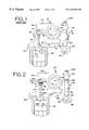
- FIG. 1 is a schematic elevation of a prior art rocker assembly mounted on an engine, showing a piston cylinder in cross-section;
- FIG. 2 is a schematic elevation of an embodiment of a rocker assembly of the present invention mounted on an engine, showing a piston cylinder in cross-section;
- FIG. 3 is an enlarged elevation of one end of the prior art rocker assembly of FIG. 1, with the socket shown in cross-section and with the rocker ball and socket in an initial at-rest position;
- FIG. 4 is an elevation of the prior art rocker assembly of FIG. 3, shown with the rocker arm and rocker ball pivoted to an interim position;
- FIG. 5 is an elevation of the prior art rocker assembly of FIG. 3, shown with the rocker arm and rocker ball pivoted to open the valve into the piston cylinder;
- FIG. 6 is an enlarged elevation of the one end of the rocker assembly of the embodiment of the present invention shown in FIG. 2, with the socket shown in cross-section and the rocker ball and socket in an initial at-rest position;
- FIG. 7 is an elevation of the rocker assembly of FIG. 6, shown with the rocker arm and rocker ball pivoted to an interim position, and with the socket and valve stem moved to an interim position;
- FIG. 8 is an elevation of the rocker assembly of FIG. 6, shown with the rocker arm and rocker ball pivoted to a further position, and with the socket and valve stem moved to a further position to open the valve into the piston cylinder;
- FIG. 9 is a perspective view of the first embodiment of the resilient retainer of the present invention.
- FIG. 10 is a top plan view of the resilient retainer of FIG. 9;
- FIG. 11 is an enlarged elevation of one end of a rocker assembly of another embodiment of the present invention, with the socket and resilient member shown in cross-section;
- FIG. 12 is an enlarged elevation of one end of a rocker assembly of another embodiment of the present invention, with the socket and resilient member shown in cross-section;
- FIG. 13 is an enlarged elevation of one end of a rocker assembly of another embodiment of the present invention, with the socket and resilient member shown in cross-section;
- FIG. 14 is a perspective view of another alternate embodiment of a resilient retainer of the present invention.
- FIG. 15 is an enlarged elevation of a part of one end of another embodiment of a rocker assembly of the present invention showing a resilient retainer with a spacer for pre-setting valve lash distance, with the resilient retainer and socket shown in cross-section;
- FIG. 16 is an enlarged elevation of a part of one end of another embodiment of a rocker assembly of the present invention showing another embodiment of a resilient retainer with a spacer for pre-setting valve lash distance;
- FIG. 17 is an enlarged elevation of a part of one end of another embodiment of a rocker assembly of the present invention showing another embodiment of a resilient retainer with a spacer for pre-setting valve lash distance.
- FIGS. 2 and 6 - 8 A first rocker assembly 100 incorporating the features of the present invention is illustrated in FIGS. 2 and 6 - 8 .
- the rocker assembly 100 of the present invention includes a rocker arm 102 mounted on a base 104 that is mounted on an engine surface 106 .
- a first end 107 of the rocker arm 102 has a bearing element 108 juxtaposed with one end 110 of a push rod 112 .
- the other end 114 of the push rod 112 bears against a cam 116 mounted on a camshaft 118 .
- the camshaft 118 is rotated by a standard drive mechanism, such as a drive chain (not shown) driven by the engine crankshaft (not shown).
- the rocker arm 102 has a second end 120 . At the second end 120 , a rocker ball 122 is secured to the rocker arm 102 . At least part of the rocker ball 122 is received in a socket 124 .
- the rocker arm 102 is pivotable on the base 104 about an axis 126 between its first end 107 and second end 120 .
- the rocker ball 122 has a curved outer surface 128 with a center of curvature 130 , a bottom 132 and a central axis 133 .
- the center of curvature 130 is between the bottom 132 of the rocker ball 122 and the second end 120 of the rocker arm 102 .
- At least part of the rocker ball defines a portion of a sphere.
- a non-spherical neck 134 extends up from the spherical portion 136 to an insert 138 received in a mating pocket in the second end 120 of the rocker arm 102 .
- the center of curvature 130 and bottom 132 of the rocker ball are both aligned along the central axis 133 .
- the socket 124 has an exterior bearing surface 140 to act against a complementary valve bearing surface 142 for pushing the valve stem 144 to open the valve.
- the socket also has an exterior non-bearing surface 146 , an interior surface 148 and an annular top 150 with a central opening 152 to receive at least part of the rocker ball 122 .
- the interior surface 148 of the socket 124 has a bearing surface 154 for contacting a portion of the rocker ball curved outer surface 128 .
- the interior surface 148 of the socket defines a curved depression, although generally not in a spherical shape in the illustrated embodiment. Instead, as in the illustrated prior art ball and socket of FIGS.
- the depressed interior surface 148 is shaped like a gothic arch, diverging from a low point or base 156 along a central axis 158 .
- the low point 156 is spaced furthest from the level of the top 150 of the socket.
- the maximum horizontal distance between the opposing sides 160 , 162 of the depressed interior surface 148 is less than the diameter 163 of the rocker ball 122 .
- the rocker assembly 100 may be designed to operate against a pair of valves, or more than two valves.
- the socket exterior bearing surface 140 may act against a bearing surface of a bridge element that operates more than one valve.
- the expression “valve bearing surface” as used herein is intended to encompass both a surface such as the individual surface 142 shown in FIGS. 6-8, as well as a bearing surface of a bridge element that spans more than one valve.
- the socket 124 of the first illustrated embodiment of the present invention is much shallower than the socket 33 of the prior art. This difference can be seen from a comparison of the illustrated prior art of FIGS. 3-5 with the first illustrated embodiment of the present invention of FIGS. 6-8.
- the bearing surface of the socket interior surface comprises a segment, designated 54 in the prior art and designated 154 in the embodiment of FIGS. 6-8.
- the top 50 of the socket is substantially above the bearing surface 54 ; when the ball and socket are aligned as shown in FIG.
- the diameter 76 of the rocker ball 32 is between the top 50 of the socket 33 and the low point 56 of the interior surface 48 of the socket 33 .
- the annular top 150 of the socket 124 is at the level of the top of the bearing surface segment 154 of the socket interior surface 148 ; when the rocker ball 122 and socket 124 are aligned with their central axes 133 , 158 co-linear, the top 150 of the socket is between the diameter 163 of the rocker ball 122 and the base or low point 156 of the interior surface 148 of the socket.
- the position of the retainer 66 depends upon the shape of the socket.
- the retainer 66 For the prior art retainer 66 to be above the diameter 76 of the rocker ball, and for the spacing defined by the retainer 66 to be less than the diameter 76 of the rocker ball, the retainer is positioned above the diameter of the rocker ball, nearer to the second end 30 of the rocker arm 12 .
- the top 50 of the socket For the retainer 66 to be so positioned, the top 50 of the socket must also be above the diameter 76 of the rocker ball, and between the center of curvature 38 and the second end 30 of the rocker arm 12 .
- the socket 124 does not need to extend to the same height because the sides of the interior surface of the socket do not function to position a retainer.
- the position of the retainer may be based upon an exterior feature of the socket, and can be based upon a feature of the exterior bearing surface 140 or the exterior non-bearing surface 146 of the socket 124 .
- the interior surface 148 of the socket need only function as a bearing surface, and therefore the height of the socket may be based upon the position of the bearing segment 154 .
- the first illustrated embodiment of the present invention allows for the use of less expensive methods of manufacture. Instead of machining the depressed interior surface 148 into a metal slug, the entire socket, including the depressed interior surface 148 , can be made of powder metal with the depressed interior surface 148 formed in a pressing operation. It should be understood that the pressing operation could comprise part of the initial formation of the green powder metal compact, or could be part of a subsequent sizing or coining operation, or any other subsequent pressing operation.
- the socket of the first illustrated embodiment of the present invention could also be made by cold-forming or cold-heading the depressed interior surface 148 into a metal workpiece. Some machining of the interior surface may be done to provide a desired finish on the bearing segment 154 , for example. Subsequent heat treatment and other standard processes may be used as well. Both of these methods of manufacture are less expensive than machining the entire depressed interior surface 148 into a metal slug.
- the advantages associated with the socket of the first illustrated embodiment relate to the unique retainer 170 used in the rocker assembly 100 .
- the first illustrated retainer 170 is a resilient element secured to the socket 124 .
- the retainer 170 extends beyond the socket 124 to a position between the annular top of the socket 150 and the second end 120 of the rocker arm 102 .
- the shape of the retainer 170 secures the socket 124 on the rocker ball 122 .
- the first illustrated retainer 170 has an annular top 172 , an integral cylindrical side 174 and an integral annular bottom 176 .
- the retainer 170 also has a central longitudinal axis shown at 188 in FIGS. 7-10.
- resilient retainer 170 need not be made as an integral element. Any of the illustrated embodiments of resilient retainers 170 , 208 , 209 , 210 , 216 , 229 , 239 , could be made of separate components connected in any conventional way.
- the retainer could be made of top and bottom components combined through standard mechanical devices, such as snap-fitting, or through the use of sonic welding or adhesives.
- the retainer could also comprise a clam-shell design, for example, folded and locked around the socket element. It should be understood that these divisions and methods of combining components are provided by way of illustration only, and that the present invention is not limited to integrally-formed retainers, to any particular division of components or to any particular method of combining components unless expressly set forth in the claims.
- the annular top 172 of the resilient retainer 170 has a central opening 178 through which a part of the rocker ball 122 extends, such as the neck 134 connecting the spherical portion 136 and the insert 138 .
- the diameter of the central opening 178 is greater than the thickness of the neck 134 and less than the diameter 163 of the spherical portion 136 of the rocker ball 122 . Since the retainer 170 is resilient, the top 172 may be deformed by the rocker ball 122 as the socket 124 is placed on the rocker ball 122 , deforming to allow the rocker ball diameter 163 to pass through the opening 178 and then returning to its original shape to retain the socket 124 on the rocker ball 122 during normal storage and use.
- the cylindrical side 174 of the resilient retainer 170 substantially surrounds the exterior non-bearing surface 146 of the socket 124 . It should be understood that the side 174 of the resilient retainer need not be cylindrical, and that gaps may be provided if desired, although it may be desirable to provide sufficient coverage to seal the interface of the bearing surfaces of the rocker ball and socket against dirt, such as abrasive contaminants.
- the annular bottom 176 of the resilient retainer 170 provides the means of securing the retainer 170 to the socket.
- the annular bottom 176 fits within a complementary annular undercut 182 in the socket 124 .
- the undercut 182 is at the exterior bearing surface 140 of the socket 124 .
- the size of the bottom 176 could be different from that shown, and that the bottom could have other shapes as well.
- the bottom could comprise an annular tab or a plurality of discrete tabs.
- the resilient retainer 170 of the first illustrated embodiment has the advantage of providing a path for the delivery of lubricant to the interface 183 of the socket exterior bearing surface 140 and the valve bearing surface 142 .
- the retainer 170 includes channels 184 from the top surface 172 , through the side 174 and to the bottom 176 .
- the channels 184 are in fluid communication with holes 185 in the top surface 172 of the resilient retainer 170 and with holes 187 in the bottom 176 of the retainer.
- the channels 184 are also in fluid communication with interior holes 189 in the interior of the side 174 of the resilient retainer 170 ; the holes 189 are at about the level of the top 150 of the socket 124 .
- the channels 184 and the holes 185 , 187 , 189 provide flow paths for liquid lubricant to be delivered to the interface 183 of the socket exterior bearing surface 140 and the valve bearing surface 142 .
- the channels 184 and holes 185 , 187 , 189 may be formed in the retainer 170 as the retainer is formed, such as by molding, or may be later cut or machined into the retainer. But since the retainer may be made of a softer material than the socket and rocker ball, formation of the channels 184 and holes 185 , 187 should be significantly less expensive compared to the channels 70 , 72 of the prior art rocker ball and socket.
- lubricant can flow through the rocker ball lubricant channel 191 to the interior surface 148 of the socket 124 .
- the lubricant can be moved through the interior holes 189 leading into the channels 184 , and from the channels 184 to the interface 183 of the bearing surfaces 140 , 142 .
- This design eliminates the need for a lubricant channel to be machined into the socket, thus saving expense.
- the channels 184 need not extend beyond the interior holes 189 to the top 172 of the retainer, but could extend solely from the interior holes 189 to the holes 187 at the bottom of the retainer.
- lubricant can be delivered through holes 193 in the second end of the rocker arm to drip around the rocker ball to the top of the resilient retainer 197 .
- like reference numbers have been used for parts like those shown in the embodiment of FIGS. 2 and 6 - 10 .
- the holes 185 in the top 172 of the retainer 197 may serve as entry holes for the lubricant.
- An annular flange 195 may be added around the retainer to catch dripping lubricant and direct it to the holes 185 in the top 172 of the retainer.
- FIG. 11 An alternative embodiment of the present invention is illustrated in FIG. 11 .
- like reference numbers have been used for parts like those shown in the embodiments of FIGS. 2 and 6 - 10 .
- the resilient retainer 208 of the embodiment of FIG. 11 is illustrated assembled with a socket 33 of the type illustrated for the prior art assembly of FIGS. 3-5, and like reference numbers have been used. It should be understood that with some variation, the resilient retainer 208 of FIG. 11 may also be used with other types of sockets, such as the socket of the present invention illustrated in FIGS. 6-8. In the embodiment of FIG.
- the inner diameter of the cylindrical side 174 of the resilient retainer 208 is about the same as the outer diameter of the socket 33 at the exterior non-bearing surface 46 , so that an interference fit secures the resilient retainer 208 to the socket 33 .
- the sides 174 of the resilient retainer may be extended down to the exterior bearing surface 42 of the socket, and that lubricant channels may be formed in the resilient retainer to deliver lubricant to the interface 74 of the bearing surfaces 42 , 44 of the socket and the valve.
- the resilient retainer 208 of the FIG. 11 embodiment could also be used with a shortened socket, as shown in FIG. 12 .
- This shortened socket 209 is similar to that shown in FIG. 11, but shortened to the level of the groove 64 in the prior art socket.
- the dimensions of the resilient retainer 208 could be varied for this design.
- Like reference numbers have been used in FIG. 12 for like parts of this embodiment, the first embodiment of FIGS. 2 and 6 - 10 , and the prior art of FIGS. 1 and 3 - 5 .
- FIG. 14 Another alternative embodiment of a resilient retainer 210 is illustrated in FIG. 14 .
- the resilient retainer has a plurality of gripper fingers 212 with detents 214 to engage complementary recesses in one of the exterior surfaces of the socket (not shown) to secure the resilient retainer 210 on the socket.
- Complementary detents and recesses may be used to secure other embodiments of the resilient retainers and sockets as well.
- the recesses may be in the exterior non-bearing surface or the exterior bearing surface of the socket, for example.
- FIG. 15 An additional feature may be used with the resilient retainer of any embodiment extending down to the level of the interface 183 between the exterior bearing surface 140 of the socket and the complementary bearing surface 142 of the valve 144 .
- This additional feature is illustrated in FIG. 15 for the embodiment of FIGS. 2 and 6 - 10 .
- the resilient retainer 216 of this embodiment has a cylindrical side 174 and an annular bottom 176 like the resilient retainer 170 of FIGS. 2 and 6 - 10 .
- the resilient retainer 216 of the embodiment of FIG. 15 may have an annular top 172 (not shown in FIG. 15) with an opening 178 of the type shown in either of FIGS. 10 or 11 , for example.
- the resilient retainer 216 includes an annular spacer 218 extending beyond the level of the exterior bearing surface 140 of the socket 124 , extending toward the valve bearing surface 142 .
- the spacer 218 is for setting the desired spacing between the exterior bearing surface 140 of the socket 124 and the valve bearing surface 140 , to thereby pre-set the valve lash distance.
- the thickness of the spacer 218 should correspond with the desired valve lash distance.
- the spacer 218 may have a thickness of 0.012 inch for an intake valve, and a thickness of 0.018 inch for an exhaust valve.
- the spacer 218 may have a thickness of 0.020 inch.
- the spacer 218 should extend to a level spaced from the level of the exterior bearing surface 140 by a distance substantially equal to the desired valve lash distance. It should also be understood that a plurality of discrete spacers could be used instead of an annular spacer.
- the socket has a second annular recess 220 spaced above the undercut 182 in the socket 124 , farther away from the interface 183 .
- the spacer 218 comprises an integral step on the resilient retainer.
- FIG. 16 An alternative embodiment is illustrated in FIG. 16 .
- the spacer 218 could comprise a detent 230 on the resilient retainer 229 that snaps back and rises under the force of the valve spring , shown at 147 in FIG. 2 . Operation of the engine could cause the retainer 170 to pop up.
- a recess such as annular recess 232 , may be provided in the socket 123 to catch the detent 230 after the retainer 170 has popped up.
- the detent 230 and bottom edge of the socket could cooperate to initially secure the resilient retainer 229 on the socket.
- the spacer 218 comprises an elongate sheet 240 having the thickness of the desired valve lash distance.
- the sheet can be attached to the resilient retainer 239 through break-away connectors 242 , for example.
- the spacer sheet 240 may also be attached to a pull tab 244 that is sized, shaped and has a surface finish that allows a mechanic to grasp the pull tab and pull the entire spacer sheet out from the interface. The spacer sheet 240 will separate from the break-away connectors 244 and may then be discarded.
- the rocker assembly includes a set mechanism 222 , shown in FIGS. 1-2, as in the prior art.
- the set mechanism 222 comprises a nut and a threaded screw at the first end 16 , 107 of the rocker arm 12 , 102 .
- the set mechanism 222 is adjusted by turning the screw to fix the distance between the exterior bearing surface 140 of the socket 124 and the valve bearing surface 142 , and then locking the screw in place with the nut.
- the spacer 218 is moved out of contact with the valve bearing surface 142 .
- the entire resilient retainer 216 is moved along the central longitudinal axis 158 of the socket away from the valve bearing surface 142 until the annular bottom 176 of the resilient retainer is received in the second recess 220 of the socket 124 ; for the embodiment of FIG. 15 or the embodiment of FIG. 16, the spacer 218 need not travel far enough to be locked into a socket or recess; the spacer 218 in these embodiments should travel far enough to maintain a permanent position spaced away from the interface 183 of the bearing surfaces 140 , 142 .
- the resilient retainer 170 , 208 , 210 , 216 , 229 , 239 includes a polymeric material.
- the entire resilient retainer 170 , 208 , 210 , 216 , 229 , 239 may comprise a polymeric material, or additives may be included, for example, to make the resilient retainer 170 , 208 , 210 , 216 , 229 , 239 , more suitable or more durable for use in the intended environment of an engine.
- the material should be one that withstands temperatures in the range of about ⁇ 50° F. to 300° F.
- the resilient retainer could also comprise a composite material, such as one of these resins combined with fibers, such as glass fibers or other fibers known in the art of making composite articles.
- the polymeric material may comprise a thermoset resin, a thermoplastic resin, or an epoxy resin, for example. Commercially available materials may be used. Standard additives may be used for any of these materials to achieve desired properties in the final product.
- the retainers can be formed in any suitable manner, such as by molding. Any necessary machining or finishing of a polymeric retainer should be substantially less expensive than machining or finishing a metallic component such as the socket of the prior art. For the selection of an appropriate material and method of forming the retainer, it is expected that one in the business of making plastic components would be consulted.
- the resilient retainer could also be made of other materials such as metal, particularly for the embodiment illustrated in FIG. 20 . It should also be understood that any materials identified above are identified for purposes of illustration only, and that the invention is not limited to any particular resin unless expressly set forth in the claims.
- the rocker assemblies of the present invention may be assembled by securing the retainer 170 , 208 , 210 , 216 , 229 , 239 to the socket 124 with at least the part of the retainer 170 , 208 , 210 , 216 , 229 , 239 defining the opening 178 for the rocker ball 122 being outside of the socket.
- the rocker ball 122 is then inserted through the opening 178 outside of the socket 124 and into the socket itself, until the diameter 163 of the rocker ball 122 is past the opening 178 in the resilient retainer.
- the part of the resilient retainer defining the opening 178 will be deformed by the rocker ball and then will return to the original dimension after the diameter of the rocker ball has passed through the opening 178 .
- the elements that deform to retain the rocker ball within the socket may be within or outside of the socket. Assembly can be done manually or is preferably automated. Since the resilient retainer essentially need only function to retain the socket on the rocker ball until the rocker assembly is mounted on the engine, the retainer can be designed so that a relatively small force will deform the portion defining the opening 178 . Slits may be provided to enable easier deformation of the portion of the socket defining the opening. Retention under forces of 5-15 lbs. should be sufficient.
- the rocker ball 122 may be canted slightly to one direction, with the central axis 133 of the rocker ball defining an angle ⁇ with the central axis 158 of the socket.
- the central axis 158 of the socket is parallel to and slightly offset from the central axis 145 of the valve stem 144 .
- the socket bearing surface 140 has slid across the valve bearing surface 142 , as shown.
- the axes 158 , 133 remain parallel with the central axis 145 of the valve stem 144 .
- the cam 116 pushes the rod 112 further upward, the first end 107 of the rocker arm 102 is raised higher, and the second end 120 of the rocker arm 102 is pushed further downward, causing further pivoting of the rocker ball 122 , and further linear and sliding movement of the socket 124 on the valve stem 144 , and further linear movement of the valve stem 144 .
- the resilient retainer 170 should be shaped so that the rocker ball 122 may pivot through its full desired range of motion without interference from the resilient retainer 170 .
- the shape and dimensions of the rocker ball 122 may also be designed to maximize the range of motion, such as by adjusting the dimensions of the neck 134 portion of the rocker ball 122 .
- gaps 74 and 183 are typically on the order of 0.012 to 0.20 inches.
- the interface 183 between the bearing surfaces 140 , 142 may be kept adequately lubricated.
- Other features of the present invention may be used with sockets and rocker balls having channels for lubricant as in the prior art.
- the socket 124 of the present invention may be made in a conventional manner, or if the socket of the first illustrated embodiment is used, it may be formed by cold heading or through a powder metal forming or pressing process. It should be understood that cold heading as used herein is intended to encompass any cold forming of a metal slug, such as extrusion.
Landscapes
- Engineering & Computer Science (AREA)
- Mechanical Engineering (AREA)
- General Engineering & Computer Science (AREA)
- Valve-Gear Or Valve Arrangements (AREA)
Abstract
Description
Claims (27)
Priority Applications (1)
| Application Number | Priority Date | Filing Date | Title |
|---|---|---|---|
| US09/332,475 US6273042B1 (en) | 1999-06-14 | 1999-06-14 | Rocker assemblies for control of engine valves and method of assembling such rocker assemblies |
Applications Claiming Priority (1)
| Application Number | Priority Date | Filing Date | Title |
|---|---|---|---|
| US09/332,475 US6273042B1 (en) | 1999-06-14 | 1999-06-14 | Rocker assemblies for control of engine valves and method of assembling such rocker assemblies |
Publications (1)
| Publication Number | Publication Date |
|---|---|
| US6273042B1 true US6273042B1 (en) | 2001-08-14 |
Family
ID=23298393
Family Applications (1)
| Application Number | Title | Priority Date | Filing Date |
|---|---|---|---|
| US09/332,475 Expired - Lifetime US6273042B1 (en) | 1999-06-14 | 1999-06-14 | Rocker assemblies for control of engine valves and method of assembling such rocker assemblies |
Country Status (1)
| Country | Link |
|---|---|
| US (1) | US6273042B1 (en) |
Cited By (19)
| Publication number | Priority date | Publication date | Assignee | Title |
|---|---|---|---|---|
| US6397805B1 (en) * | 1999-06-28 | 2002-06-04 | Michael G. Knickerbocker | Retainer for rocker arm coupling in an internal combustion engine |
| US6463898B1 (en) * | 2000-11-20 | 2002-10-15 | Cummins Engine Company, Inc. | Rocker lever ball socket retainer |
| US6470843B2 (en) * | 2001-02-16 | 2002-10-29 | Detroit Diesel Corporation | Rocker arm adjustment screw assembly |
| US6557507B2 (en) * | 2001-03-30 | 2003-05-06 | Caterpillar Inc. | Rocker arm assembly |
| US6830022B2 (en) * | 2001-10-30 | 2004-12-14 | International Engine Intellectual Property Company, Llc | Valve actuation linkage mechanism |
| US20050183684A1 (en) * | 2004-02-25 | 2005-08-25 | James Strepek | Valve operating system in an internal combustion engine |
| WO2006132580A1 (en) * | 2005-06-07 | 2006-12-14 | Scania Cv Ab (Publ) | Apparatus for transferring a movement from a rocker arm to a valve in a combustion engine and a combustion engine comprising such an apparatus |
| US20070119397A1 (en) * | 2005-11-30 | 2007-05-31 | Ford Global Technologies, Llc | Engine and valvetrain with dual pushrod lifters and independent lash adjustment |
| US20070204826A1 (en) * | 2006-03-03 | 2007-09-06 | Ford Global Technologies, Llc | Engine and valvetrain with compact rocker arm and fulcrum assembly for internal combustion engines |
| US20080000440A1 (en) * | 2004-12-14 | 2008-01-03 | Christophe Reckzugel | Support arrangement for cam follower for actuating a gas exchange valve of an internal combustion engine |
| US20080083382A1 (en) * | 2006-10-06 | 2008-04-10 | Ford Global Technologies, Llc | Pushrod engine with multiple independent lash adjusters for each pushrod |
| US20080202456A1 (en) * | 2007-02-28 | 2008-08-28 | Ford Global Technologies, Llc | Engine/valvetrain with shaft-mounted cam followers having dual independent lash adjusters |
| US20090044775A1 (en) * | 2007-08-19 | 2009-02-19 | Ford Global Technologies, Llc | Hydraulic Lash Adjuster With Damping Device |
| EP1983162A3 (en) * | 2007-04-17 | 2009-12-09 | Gnutti Carlo S.p.A. | A connection device for connecting rocker, valve or injection assemblies in internal combustion engines |
| WO2011016946A1 (en) * | 2009-08-04 | 2011-02-10 | International Engine Intellectual Property Company, Llc | Bridge and pivot foot arrangement for operating engine cylinder valves |
| US20110239967A1 (en) * | 2010-03-30 | 2011-10-06 | Gnutti Ltd. | Valve bridge |
| GB2490701A (en) * | 2011-05-10 | 2012-11-14 | Perkins Engines Co Ltd | Valve actuator assembly comprising a ball and socket connector having surface oil channels |
| US9567960B2 (en) | 2014-03-25 | 2017-02-14 | Cummins Inc. | Fuel pump tappet assembly |
| JP2021156188A (en) * | 2020-03-26 | 2021-10-07 | 株式会社オティックス | Valve gear |
Citations (10)
| Publication number | Priority date | Publication date | Assignee | Title |
|---|---|---|---|---|
| US3859973A (en) * | 1971-12-27 | 1975-01-14 | Allis Chalmers | Timing device for fuel injector |
| US4164062A (en) * | 1977-12-12 | 1979-08-14 | Sullivan Jack W | Ball and socket linkage and bearing assembly and method of fabricating |
| US4708103A (en) * | 1985-11-21 | 1987-11-24 | Motomak Motorenbau, Maschinen- Und Werkzeugfabrik, Konstruktionen Gmbh | Hydraulic valve clearance compensation device |
| US4724805A (en) * | 1987-02-24 | 1988-02-16 | General Motors Corporation | Engine valve train module |
| US4856468A (en) * | 1987-07-30 | 1989-08-15 | Ina Walzlager Schaeffler Kg | Ball-and-socket joint |
| US5570665A (en) * | 1995-04-04 | 1996-11-05 | Chrysler Corporation | Valve train for internal combustion engine |
| US5632237A (en) * | 1995-08-07 | 1997-05-27 | Hy-Lift Division Of Spx Corporation | Hydraulic lash compensating element assembly |
| US5640934A (en) * | 1995-02-20 | 1997-06-24 | Fugi Oozx Inc. | Method of adjusting a valve clearance |
| US5645023A (en) * | 1996-04-08 | 1997-07-08 | Chrysler Corporation | Valve train for an internal combustion engine |
| US5706771A (en) * | 1996-12-23 | 1998-01-13 | General Motors Corporation | Hydraulic element assembly |
-
1999
- 1999-06-14 US US09/332,475 patent/US6273042B1/en not_active Expired - Lifetime
Patent Citations (10)
| Publication number | Priority date | Publication date | Assignee | Title |
|---|---|---|---|---|
| US3859973A (en) * | 1971-12-27 | 1975-01-14 | Allis Chalmers | Timing device for fuel injector |
| US4164062A (en) * | 1977-12-12 | 1979-08-14 | Sullivan Jack W | Ball and socket linkage and bearing assembly and method of fabricating |
| US4708103A (en) * | 1985-11-21 | 1987-11-24 | Motomak Motorenbau, Maschinen- Und Werkzeugfabrik, Konstruktionen Gmbh | Hydraulic valve clearance compensation device |
| US4724805A (en) * | 1987-02-24 | 1988-02-16 | General Motors Corporation | Engine valve train module |
| US4856468A (en) * | 1987-07-30 | 1989-08-15 | Ina Walzlager Schaeffler Kg | Ball-and-socket joint |
| US5640934A (en) * | 1995-02-20 | 1997-06-24 | Fugi Oozx Inc. | Method of adjusting a valve clearance |
| US5570665A (en) * | 1995-04-04 | 1996-11-05 | Chrysler Corporation | Valve train for internal combustion engine |
| US5632237A (en) * | 1995-08-07 | 1997-05-27 | Hy-Lift Division Of Spx Corporation | Hydraulic lash compensating element assembly |
| US5645023A (en) * | 1996-04-08 | 1997-07-08 | Chrysler Corporation | Valve train for an internal combustion engine |
| US5706771A (en) * | 1996-12-23 | 1998-01-13 | General Motors Corporation | Hydraulic element assembly |
Cited By (31)
| Publication number | Priority date | Publication date | Assignee | Title |
|---|---|---|---|---|
| US6397805B1 (en) * | 1999-06-28 | 2002-06-04 | Michael G. Knickerbocker | Retainer for rocker arm coupling in an internal combustion engine |
| US6463898B1 (en) * | 2000-11-20 | 2002-10-15 | Cummins Engine Company, Inc. | Rocker lever ball socket retainer |
| US6725819B2 (en) | 2000-11-20 | 2004-04-27 | Cummins Engine Company, Inc. | Rocker lever ball socket retainer |
| US6470843B2 (en) * | 2001-02-16 | 2002-10-29 | Detroit Diesel Corporation | Rocker arm adjustment screw assembly |
| US6557507B2 (en) * | 2001-03-30 | 2003-05-06 | Caterpillar Inc. | Rocker arm assembly |
| US6830022B2 (en) * | 2001-10-30 | 2004-12-14 | International Engine Intellectual Property Company, Llc | Valve actuation linkage mechanism |
| US20050183684A1 (en) * | 2004-02-25 | 2005-08-25 | James Strepek | Valve operating system in an internal combustion engine |
| US20080000440A1 (en) * | 2004-12-14 | 2008-01-03 | Christophe Reckzugel | Support arrangement for cam follower for actuating a gas exchange valve of an internal combustion engine |
| WO2006132580A1 (en) * | 2005-06-07 | 2006-12-14 | Scania Cv Ab (Publ) | Apparatus for transferring a movement from a rocker arm to a valve in a combustion engine and a combustion engine comprising such an apparatus |
| CN100577990C (en) * | 2005-06-07 | 2010-01-06 | 斯堪尼亚有限公司 | Device for transmitting motion from a lever arm to a valve in an internal combustion engine and an internal combustion engine comprising such a device |
| US20070119397A1 (en) * | 2005-11-30 | 2007-05-31 | Ford Global Technologies, Llc | Engine and valvetrain with dual pushrod lifters and independent lash adjustment |
| US7617807B2 (en) | 2005-11-30 | 2009-11-17 | Ford Global Technologies, Llc | Engine and valvetrain with dual pushrod lifters and independent lash adjustment |
| US20070204826A1 (en) * | 2006-03-03 | 2007-09-06 | Ford Global Technologies, Llc | Engine and valvetrain with compact rocker arm and fulcrum assembly for internal combustion engines |
| US7418936B2 (en) | 2006-03-03 | 2008-09-02 | Ford Global Technologies, Llc | Engine and valvetrain with compact rocker arm and fulcrum assembly for internal combustion engines |
| US7424876B2 (en) | 2006-10-06 | 2008-09-16 | Ford Global Technologies, Llc | Pushrod engine with multiple independent lash adjusters for each pushrod |
| US20080283011A1 (en) * | 2006-10-06 | 2008-11-20 | Ford Global Technologies, Llc | Pushrod engine with multiple independent lash adjusters for each pushrod |
| US20080083382A1 (en) * | 2006-10-06 | 2008-04-10 | Ford Global Technologies, Llc | Pushrod engine with multiple independent lash adjusters for each pushrod |
| US7861680B2 (en) | 2006-10-06 | 2011-01-04 | Ford Global Technologies, Llc | Pushrod engine with multiple independent lash adjusters for each pushrod |
| US7458350B2 (en) | 2007-02-28 | 2008-12-02 | Ford Global Technologies, Llc | Engine/valvetrain with shaft-mounted cam followers having dual independent lash adjusters |
| US20080202456A1 (en) * | 2007-02-28 | 2008-08-28 | Ford Global Technologies, Llc | Engine/valvetrain with shaft-mounted cam followers having dual independent lash adjusters |
| EP1983162A3 (en) * | 2007-04-17 | 2009-12-09 | Gnutti Carlo S.p.A. | A connection device for connecting rocker, valve or injection assemblies in internal combustion engines |
| US20090044775A1 (en) * | 2007-08-19 | 2009-02-19 | Ford Global Technologies, Llc | Hydraulic Lash Adjuster With Damping Device |
| US7845327B2 (en) | 2007-08-19 | 2010-12-07 | Ford Global Technologies, Llc | Hydraulic lash adjuster with damping device |
| WO2011016946A1 (en) * | 2009-08-04 | 2011-02-10 | International Engine Intellectual Property Company, Llc | Bridge and pivot foot arrangement for operating engine cylinder valves |
| US8006661B2 (en) | 2009-08-04 | 2011-08-30 | International Engine Intellectual Property Company, Llc | Bridge and pivot foot arrangement for operating engine cylinder valves |
| EP2462322A4 (en) * | 2009-08-04 | 2013-06-05 | Int Engine Intellectual Prop | DECK ARRANGEMENT AND PIVOT FOOT FOR OPERATING ENGINE CYLINDER VALVES |
| US20110239967A1 (en) * | 2010-03-30 | 2011-10-06 | Gnutti Ltd. | Valve bridge |
| GB2490701A (en) * | 2011-05-10 | 2012-11-14 | Perkins Engines Co Ltd | Valve actuator assembly comprising a ball and socket connector having surface oil channels |
| GB2490701B (en) * | 2011-05-10 | 2013-08-21 | Perkins Engines Co Ltd | A connection member for interconnecting a rocker arm and a push rod |
| US9567960B2 (en) | 2014-03-25 | 2017-02-14 | Cummins Inc. | Fuel pump tappet assembly |
| JP2021156188A (en) * | 2020-03-26 | 2021-10-07 | 株式会社オティックス | Valve gear |
Similar Documents
| Publication | Publication Date | Title |
|---|---|---|
| US6273042B1 (en) | Rocker assemblies for control of engine valves and method of assembling such rocker assemblies | |
| US20150090211A1 (en) | Mechanical System, Injection Pump And Valve Actuator Comprising Such A Mechanical System And Manufacturing Method | |
| US20150096514A1 (en) | Positive control (desmodromic) valve systems for internal combustion engines | |
| US4502428A (en) | Lash adjuster with follower body retainer | |
| CN110159383B (en) | Switchable rocker arm with clearance adjustment | |
| US4653441A (en) | Engine rocker arm assembly | |
| US6412460B1 (en) | Valve operating system in internal combustion engine | |
| EP0758046A1 (en) | Hydraulic lash compensating element assembly | |
| US7980216B2 (en) | Rocker arm assembly having slider roller oil pumping features | |
| EP2462322B1 (en) | Bridge and pivot foot arrangement for operating engine cylinder valves | |
| US5706770A (en) | Valve drive of an internal combustion engine | |
| EP1891304B1 (en) | Apparatus for transferring a movement from a rocker arm to a valve in a combustion engine and a combustion engine comprising such an apparatus | |
| EP1288446B1 (en) | A tappet for an internal combustion engine | |
| EP1479876A1 (en) | Rocker arm with mechanical lash adjuster | |
| GB2347464A (en) | I.c. engine rocker lever and tappet socket assembly | |
| US8171906B2 (en) | Valve lifter guide and method of using same | |
| JP5241533B2 (en) | Rocker arm | |
| US10428699B2 (en) | Pivot bearing of a hydraulic clearance compensation element | |
| EP2891774A1 (en) | Direct-action valve lifter for internal combustion engine | |
| CN212202156U (en) | Roller tappet | |
| US11149593B2 (en) | Tappet assembly with formed anti-rotation alignment device | |
| US20030172886A1 (en) | Variable valve actuation mechanism having partial wrap bearings for output cams and frames | |
| US6470843B2 (en) | Rocker arm adjustment screw assembly | |
| CN216642230U (en) | Rocker pin ball and engine valve train provided with same | |
| US10871087B2 (en) | Switchable rocker arm |
Legal Events
| Date | Code | Title | Description |
|---|---|---|---|
| AS | Assignment |
Owner name: AMSTED INDUSTRIES INCORPORATED, ILLINOIS Free format text: ASSIGNMENT OF ASSIGNORS INTEREST;ASSIGNORS:PEREZ, VINCENT M.;REMPFER, DAVID E.;REEL/FRAME:010138/0577 Effective date: 19990614 |
|
| AS | Assignment |
Owner name: CITICORP USA, INC., DELAWARE Free format text: SECURITY AGREEMENT;ASSIGNOR:BURGESS-NORTON MFG. CO.;REEL/FRAME:011231/0434 Effective date: 20000929 |
|
| STCF | Information on status: patent grant |
Free format text: PATENTED CASE |
|
| AS | Assignment |
Owner name: CITICORP USA, INC., NEW YORK Free format text: SECURITY INTEREST;ASSIGNORS:AMSTED INDUSTRIES INCORPORATED;BALTIMORE AIRCOIL COMPANY, INC.;VARLEN CORPORATION;AND OTHERS;REEL/FRAME:014580/0116 Effective date: 20030930 |
|
| AS | Assignment |
Owner name: AMSTED INDUSTRIES INCORPORATED, ILLINOIS Free format text: RELEASE AGREEMENT;ASSIGNOR:CITICORP USA, INC.;REEL/FRAME:014242/0943 Effective date: 20040107 |
|
| AS | Assignment |
Owner name: WH INDUSTRIES INC., NEW JERSEY Free format text: ASSIGNMENT OF ASSIGNORS INTEREST;ASSIGNOR:AMSTED INDUSTRIES INCORPORATED;REEL/FRAME:015428/0932 Effective date: 20040123 |
|
| AS | Assignment |
Owner name: PNC BANK, NATIONAL ASSOCIATION, NEW JERSEY Free format text: SECURITY AGREEMENT;ASSIGNOR:WH INDUSTRIES INC.;REEL/FRAME:015442/0389 Effective date: 20041210 |
|
| REMI | Maintenance fee reminder mailed | ||
| FPAY | Fee payment |
Year of fee payment: 4 |
|
| SULP | Surcharge for late payment | ||
| AS | Assignment |
Owner name: WH INDUSTRIES, INC., NEW JERSEY Free format text: ASSIGNMENT OF ASSIGNORS INTEREST;ASSIGNOR:PNC BANK, NATIONAL ASSOCIATION;REEL/FRAME:019725/0774 Effective date: 20070731 |
|
| AS | Assignment |
Owner name: CUMMINS, INC., INDIANA Free format text: ASSIGNMENT OF ASSIGNORS INTEREST;ASSIGNOR:WH INDUSTRIES, INC.;REEL/FRAME:019744/0538 Effective date: 20070511 |
|
| FPAY | Fee payment |
Year of fee payment: 8 |
|
| AS | Assignment |
Owner name: PNC BANK, NATIONAL ASSOCIATION, NEW YORK Free format text: SECURITY AGREEMENT;ASSIGNOR:WH INDUSTRIES INC.;REEL/FRAME:026909/0563 Effective date: 20110906 |
|
| FPAY | Fee payment |
Year of fee payment: 12 |
|
| AS | Assignment |
Owner name: WH INDUSTRIES INC, NEW JERSEY Free format text: RELEASE BY SECURED PARTY;ASSIGNOR:PNC BANK NATIONAL ASSOCIATION;REEL/FRAME:039564/0994 Effective date: 20160829 Owner name: WH INDUSTRIES INC, NEW JERSEY Free format text: RELEASE BY SECURED PARTY;ASSIGNOR:PNC BANK NATIONAL ASSOCIATION;REEL/FRAME:039565/0068 Effective date: 20160829 |