US6268733B1 - Field service system for analog current analysis of digitally controlled power devices - Google Patents
Field service system for analog current analysis of digitally controlled power devices Download PDFInfo
- Publication number
- US6268733B1 US6268733B1 US09/411,577 US41157799A US6268733B1 US 6268733 B1 US6268733 B1 US 6268733B1 US 41157799 A US41157799 A US 41157799A US 6268733 B1 US6268733 B1 US 6268733B1
- Authority
- US
- United States
- Prior art keywords
- current
- electromechanical device
- digital
- field service
- current profile
- Prior art date
- Legal status (The legal status is an assumption and is not a legal conclusion. Google has not performed a legal analysis and makes no representation as to the accuracy of the status listed.)
- Expired - Fee Related
Links
- 230000015556 catabolic process Effects 0.000 claims abstract description 5
- 238000006731 degradation reaction Methods 0.000 claims abstract description 5
- 238000001514 detection method Methods 0.000 claims abstract 3
- 238000000034 method Methods 0.000 claims description 6
- 230000004044 response Effects 0.000 claims description 6
- 238000012544 monitoring process Methods 0.000 claims description 5
- 239000000523 sample Substances 0.000 claims description 3
- 230000036962 time dependent Effects 0.000 claims 5
- 230000001419 dependent effect Effects 0.000 claims 3
- 230000000977 initiatory effect Effects 0.000 claims 1
- 230000000007 visual effect Effects 0.000 claims 1
- 238000012937 correction Methods 0.000 abstract description 2
- 238000003745 diagnosis Methods 0.000 abstract description 2
- 238000012545 processing Methods 0.000 description 29
- 238000012360 testing method Methods 0.000 description 15
- 239000000758 substrate Substances 0.000 description 14
- 108091008695 photoreceptors Proteins 0.000 description 13
- 238000011161 development Methods 0.000 description 9
- 239000002131 composite material Substances 0.000 description 6
- 230000009286 beneficial effect Effects 0.000 description 4
- 238000012546 transfer Methods 0.000 description 4
- 230000000694 effects Effects 0.000 description 3
- 230000006870 function Effects 0.000 description 3
- 230000009471 action Effects 0.000 description 2
- 150000002500 ions Chemical class 0.000 description 2
- 239000002245 particle Substances 0.000 description 2
- 230000008569 process Effects 0.000 description 2
- 230000006978 adaptation Effects 0.000 description 1
- 238000004140 cleaning Methods 0.000 description 1
- 239000003086 colorant Substances 0.000 description 1
- 238000004891 communication Methods 0.000 description 1
- 230000003111 delayed effect Effects 0.000 description 1
- 238000002405 diagnostic procedure Methods 0.000 description 1
- 238000003384 imaging method Methods 0.000 description 1
- 230000001939 inductive effect Effects 0.000 description 1
- 238000003780 insertion Methods 0.000 description 1
- 230000037431 insertion Effects 0.000 description 1
- 239000011159 matrix material Substances 0.000 description 1
- 238000005259 measurement Methods 0.000 description 1
- 238000012986 modification Methods 0.000 description 1
- 230000004048 modification Effects 0.000 description 1
- 238000011022 operating instruction Methods 0.000 description 1
- 230000008439 repair process Effects 0.000 description 1
- 238000000926 separation method Methods 0.000 description 1
Images


Classifications
-
- G—PHYSICS
- G01—MEASURING; TESTING
- G01R—MEASURING ELECTRIC VARIABLES; MEASURING MAGNETIC VARIABLES
- G01R31/00—Arrangements for testing electric properties; Arrangements for locating electric faults; Arrangements for electrical testing characterised by what is being tested not provided for elsewhere
- G01R31/28—Testing of electronic circuits, e.g. by signal tracer
- G01R31/282—Testing of electronic circuits specially adapted for particular applications not provided for elsewhere
- G01R31/2829—Testing of circuits in sensor or actuator systems
Definitions
- a field-service instrument includes an interface to a digital control bus. That interface includes a current sensor for monitoring the current on a return line.
- the field-service instrument further includes a bus controller that applies digital control signals to the control bus via the interface. Those digital control signals cause electrical power to be applied to an electromechanical device being tested.
- a current monitor monitors the current drawn by the electromechanical device such that a current profile of that electromechanical device over a time is determined.
- the field-service instrument further includes a fault determination network that compares the current profile of the electromechanical device being tested with a baseline current profile. The fault determination network then determines whether the electromechanical device being tested is acceptable.
- the baseline current profile includes information useful for enabling the fault determination network to identify a degraded electromechanical device so that fault correction before actual failure is feasible.
- FIG. 2 which illustrates a bus used in the electrophotographic printing machine according to FIG. 1;
- FIG. 4 which illustrates an exemplary analog current profiles for a solenoid
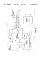
- the image area is that part of the photoreceptor belt which is to receive the various actions and toner layers that produce the final composite color image. While the photoreceptor belt may have numerous image areas, since each image area is processed in the same way a description of the processing of one image area suffices to explain the operation of the printing machine 8 .
- the DC corotron charges the image area in preparation for exposure to create a latent image for black toner.
- the DC corotron might charge the image area to a substantially uniform potential of about ⁇ 500 volts. It should be understood that the actual charge placed on the photoreceptor will depend upon many variables, such as the black toner mass that is to be developed and the settings of the black development station (see below).
- the image area After passing the charging station the image area advances to an exposure station 24 A.
- the charged image area is exposed to a modulated laser beam 26 A from a raster output scanner 27 A that raster scans the image area such that an electrostatic latent representation of a black image is produced.
- the exposed image area with the black latent image passes a black development station 32 that advances black toner 34 onto the image area so as to develop a black toner image.
- Biasing is such as to effect discharged area development (DAD) of the lower (less negative) of the two voltage levels on the image area.
- DAD discharged area development
- the charged black toner 34 adheres to the exposed areas of the image area, thereby causing the voltage of the illuminated parts of the image area to be about ⁇ 200 volts.
- the non-illuminated parts of the image area remain at about ⁇ 500 volts.
- a recharging station 36 comprised of a DC corotron 38 and an AC scorotron 40 .
- the recharging station 36 recharges the image area and its black toner layer using a technique known as split recharging. Briefly, the DC corotron 38 overcharges the image area to a voltage level greater than that desired when the image area is recharged, while the AC scorotron 40 reduces that voltage level to that which is desired.
- Split recharging serves to substantially eliminate voltage differences between toned areas and untoned areas and to reduce the level of residual charge remaining on the previously toned areas.
- the recharged image area with its black toner layer then advances to an exposure station 24 B.
- a laser beam 26 B from a raster output scanner 27 B exposes the image area to produce an electrostatic latent representation of a yellow image.
- the now re-exposed image area then advances to a yellow development station 46 that deposits yellow toner 48 onto the image area.
- a recharging station 50 where a DC scorotron 52 and an AC scorotron 54 split recharge the image area.
- the recharged image area with its toner layers then advances to an exposure station 24 D.
- a laser beam 26 D from a raster output scanner 27 D exposes the image area to produce an electrostatic latent representation of a cyan image.
- the re-exposed image area advances past a cyan development station 66 that deposits cyan toner 68 onto the image area.
- cyan development station 66 deposits cyan toner 68 onto the image area.
- four colors of toner are on the image area, resulting in a composite color image.
- the composite color toner image is comprised of individual toner particles that have charge potentials that vary widely. Directly transferring such a composite toner image onto a substrate would result in a degraded final image. Therefore it is beneficial to prepare the composite color toner image for transfer.
- a pretransfer erase lamp 72 discharges the image area to produce a relatively low charge level on the image area.
- the image area then passes a pretransfer DC scorotron 80 that performs a pre-transfer charging function.
- the image area continues to advance in the direction 12 past the driven roller 14 .
- a substrate 82 is then placed over the image area using a sheet feeder (which is not shown).
- As the substrate continues its travel is passes a detack corotron 86 . That corotron neutralizes some of the charge on the substrate to assist separation of the substrate from the photoreceptor 10 .
- the lip of the substrate 82 moves around the tension roller 18 the lip separates from the photoreceptor.
- the substrate is then directed into a fuser 90 where a fuser belt 112 disposed between a heated fuser roller 114 and a pressure roller 122 create a nip through which the substrate 82 passes.
- the fuser also includes an idle roller 116 .
- the combination of pressure and heat at the nip causes the composite color toner image to fuse into the substrate.
- a chute guides the substrate to a catch tray, also not shown, for removal by an operator.
- the image area continues its travel and passes a preclean erase lamp 98 . That lamp neutralizes most of the charge remaining on the photoreceptor belt. After passing the preclean erase lamp the residual toner and/or debris on the photoreceptor is removed at a cleaning station 99 . The image area then passes once again to the precharge erase lamp 21 and the start of another printing cycle.
- the electrophotographic printing machine 8 is a highly complex machine whose operation depends upon proper operation and timing of all of the machine's systems and sub-systems.
- the electrophotographic printing machine 8 includes numerous electromechanical power devices, including not only the motor 20 , but also a motor inside each developer, a motor that drives the fuser, and numerous relays and solenoids in the various paper handlers, document feeders, and finishing stations that, while not specifically shown, are well-known to those skilled in the art.
- FIG. 2 shows a solenoid 220 . Such a solenoid might be used for feeding paper through the printing machine.
- the printer 8 also includes a system controller 101 (shown in four places in FIG. 1) that controls the overall operation of the printer and that applies video information to the exposure stations.
- the system controller specifically includes a processing unit 190 , reference FIGS. 2, 3 , and 5 .
- the system controller 101 also includes a connector 192 that connects to the processing unit 190 .
- Communication between the system controller 101 and the various systems and subsystems, represented by a generic module 194 is via a bus 200 .
- the module represents a system that assists the enablement of one or more of the processing stations and/or steps discussed previously.
- electrophotographic printing machine 8 While the electrophotographic printing machine 8 described in relation to FIGS. 1 and 2 is beneficial, it is often difficult to isolate and/or identify faults in the electromechanical devices. This is particularly true when field servicing since the electrophotographic printing machine 8 is then either fully or almost fully assembled. It is also difficult to determine inherent latencies between digital control signals and actual operation of the electromechanical devices.
- the potential drop across the sensing resistor 308 is applied to a data acquisition card 311 .
- a typical sensing resistor might be 0.01 ohms.
- the data acquisition card 311 includes an analog-to-digital converter 312 and a digital processor 314 that connects to the central processing unit. Also connected to the central processing unit 306 is a memory card 310 .
- the central processing unit then recalls baseline information from the memory 310 and, using preprogrammed criteria, compares baseline information to the information from the digital processor unit 314 . Based upon that comparison the central processing unit provides a field-service operator with diagnostic information about the electromechanical device, here the solenoid 220 , being tested. Such diagnostic information might take the form of a good-bad alarm, a display that provides an “acceptable” current trace and the measured current trace of the electromechanical device 220 under test, or a numerical indication of the quality of the electromechanical device under test.
Landscapes
- Physics & Mathematics (AREA)
- Electromagnetism (AREA)
- Engineering & Computer Science (AREA)
- General Engineering & Computer Science (AREA)
- General Physics & Mathematics (AREA)
- Measurement Of Current Or Voltage (AREA)
- Testing Electric Properties And Detecting Electric Faults (AREA)
- Control Or Security For Electrophotography (AREA)
Abstract
Description
Claims (19)
Priority Applications (2)
| Application Number | Priority Date | Filing Date | Title |
|---|---|---|---|
| US09/411,577 US6268733B1 (en) | 1999-10-04 | 1999-10-04 | Field service system for analog current analysis of digitally controlled power devices |
| JP2000288876A JP4555449B2 (en) | 1999-10-04 | 2000-09-22 | Field service equipment |
Applications Claiming Priority (1)
| Application Number | Priority Date | Filing Date | Title |
|---|---|---|---|
| US09/411,577 US6268733B1 (en) | 1999-10-04 | 1999-10-04 | Field service system for analog current analysis of digitally controlled power devices |
Publications (1)
| Publication Number | Publication Date |
|---|---|
| US6268733B1 true US6268733B1 (en) | 2001-07-31 |
Family
ID=23629498
Family Applications (1)
| Application Number | Title | Priority Date | Filing Date |
|---|---|---|---|
| US09/411,577 Expired - Fee Related US6268733B1 (en) | 1999-10-04 | 1999-10-04 | Field service system for analog current analysis of digitally controlled power devices |
Country Status (2)
| Country | Link |
|---|---|
| US (1) | US6268733B1 (en) |
| JP (1) | JP4555449B2 (en) |
Cited By (6)
| Publication number | Priority date | Publication date | Assignee | Title |
|---|---|---|---|---|
| US20040036478A1 (en) * | 2002-05-06 | 2004-02-26 | Enikia L.L.C. | Method and system for power line network fault detection and quality monitoring |
| US6782345B1 (en) * | 2000-10-03 | 2004-08-24 | Xerox Corporation | Systems and methods for diagnosing electronic systems |
| US20070159978A1 (en) * | 2006-01-10 | 2007-07-12 | Honeywell International Inc. | Remote communications diagnostics using analog data analysis |
| US20090261855A1 (en) * | 2008-04-22 | 2009-10-22 | Xerox Corporation | Method and system for incorporating electronic signature analysis in low voltage power supplies |
| US20160181738A1 (en) * | 2014-12-19 | 2016-06-23 | Hong Fu Jin Precision Industry (Wuhan) Co., Ltd. | Automatic telescopic connector and electronic device using the same |
| CN113787845A (en) * | 2021-09-17 | 2021-12-14 | 上海商米科技集团股份有限公司 | Power supply control circuit and method of printer and printer |
Citations (3)
| Publication number | Priority date | Publication date | Assignee | Title |
|---|---|---|---|---|
| US4636939A (en) * | 1982-07-16 | 1987-01-13 | At&T Bell Laboratories | Parallel bus protocol |
| US5357519A (en) * | 1991-10-03 | 1994-10-18 | Apple Computer, Inc. | Diagnostic system |
| US6097794A (en) * | 1993-03-25 | 2000-08-01 | U.S. Robotics Access Corp. | Host computer digital signal processing system for communicating over voice-grade telephone channels |
Family Cites Families (2)
| Publication number | Priority date | Publication date | Assignee | Title |
|---|---|---|---|---|
| IT1195155B (en) * | 1986-09-09 | 1988-10-12 | Fiat Auto Spa | SYSTEM FOR DIAGNOSIS OF ANOMALIES OR FAULTS OF A MULTIPLE OF TYPES OF ELECTRONIC CONTROL SYSTEMS INSTALLED ON BOARD MOTOR VEHICLES |
| JP2966958B2 (en) * | 1990-04-20 | 1999-10-25 | テキサス インスツルメンツ インコーポレイテツド | System analysis apparatus and method |
-
1999
- 1999-10-04 US US09/411,577 patent/US6268733B1/en not_active Expired - Fee Related
-
2000
- 2000-09-22 JP JP2000288876A patent/JP4555449B2/en not_active Expired - Fee Related
Patent Citations (3)
| Publication number | Priority date | Publication date | Assignee | Title |
|---|---|---|---|---|
| US4636939A (en) * | 1982-07-16 | 1987-01-13 | At&T Bell Laboratories | Parallel bus protocol |
| US5357519A (en) * | 1991-10-03 | 1994-10-18 | Apple Computer, Inc. | Diagnostic system |
| US6097794A (en) * | 1993-03-25 | 2000-08-01 | U.S. Robotics Access Corp. | Host computer digital signal processing system for communicating over voice-grade telephone channels |
Cited By (9)
| Publication number | Priority date | Publication date | Assignee | Title |
|---|---|---|---|---|
| US6782345B1 (en) * | 2000-10-03 | 2004-08-24 | Xerox Corporation | Systems and methods for diagnosing electronic systems |
| US20040036478A1 (en) * | 2002-05-06 | 2004-02-26 | Enikia L.L.C. | Method and system for power line network fault detection and quality monitoring |
| US6917888B2 (en) * | 2002-05-06 | 2005-07-12 | Arkados, Inc. | Method and system for power line network fault detection and quality monitoring |
| US20070159978A1 (en) * | 2006-01-10 | 2007-07-12 | Honeywell International Inc. | Remote communications diagnostics using analog data analysis |
| US8780726B2 (en) | 2006-01-10 | 2014-07-15 | Honeywell International Inc. | Remote communications diagnostics using analog data analysis |
| US20090261855A1 (en) * | 2008-04-22 | 2009-10-22 | Xerox Corporation | Method and system for incorporating electronic signature analysis in low voltage power supplies |
| US8326551B2 (en) | 2008-04-22 | 2012-12-04 | Xerox Corporation | Method and system for incorporating electronic signature analysis in low voltage power supplies |
| US20160181738A1 (en) * | 2014-12-19 | 2016-06-23 | Hong Fu Jin Precision Industry (Wuhan) Co., Ltd. | Automatic telescopic connector and electronic device using the same |
| CN113787845A (en) * | 2021-09-17 | 2021-12-14 | 上海商米科技集团股份有限公司 | Power supply control circuit and method of printer and printer |
Also Published As
| Publication number | Publication date |
|---|---|
| JP2001147248A (en) | 2001-05-29 |
| JP4555449B2 (en) | 2010-09-29 |
Similar Documents
| Publication | Publication Date | Title |
|---|---|---|
| US6047142A (en) | Toner age calculation in print engine diagnostic | |
| US6611665B2 (en) | Method and apparatus using a biased transfer roll as a dynamic electrostatic voltmeter for system diagnostics and closed loop process controls | |
| US6268733B1 (en) | Field service system for analog current analysis of digitally controlled power devices | |
| US20100247120A1 (en) | Image forming apparatus | |
| EP1591841B1 (en) | Method for calculating toner age and a method for calculating carrier age for use in print engine diagnostics | |
| US8639141B2 (en) | Image forming apparatus | |
| JP2014002003A (en) | Electronic device | |
| EP0797129B1 (en) | Method of cleaning a contact charger of an electrophotographic apparatus | |
| US6223006B1 (en) | Photoreceptor charge control | |
| US5359393A (en) | Method and apparatus for measuring photoreceptor voltage potential using a charging device | |
| EP0479157B1 (en) | Image forming apparatus employing LED printing head | |
| EP1107070B1 (en) | Method and apparatus for adaptive black solid area estimation in a xerographic apparatus | |
| US6233413B1 (en) | Set-up and diagnosis of printing device electrophotographic cleaning station using potential measurement | |
| US20060222382A1 (en) | Minimum replenisher dispense strategy for improved xerographic stability | |
| JPH08166727A (en) | Image forming device | |
| US20020067929A1 (en) | High voltage developer bias multiplexer | |
| EP0571186A1 (en) | Apparatus and method for removing developer material | |
| JPH06308844A (en) | Image forming device | |
| US7298980B2 (en) | Feed forward and feedback toner concentration control utilizing post transfer sensing for TC set point adjustment for an imaging system | |
| EP0640885A2 (en) | A charging device | |
| CA2375064C (en) | Electrophotographic process control and diagnostic system | |
| EP0530031A2 (en) | Method for determining photoreceptor potentials | |
| JP2016153818A (en) | Power supply device, image forming apparatus, and power supply method | |
| EP1134623B1 (en) | Image forming apparatus with variable toning bias offset service utility | |
| JP2778906B2 (en) | Three-level image forming method and apparatus |
Legal Events
| Date | Code | Title | Description |
|---|---|---|---|
| AS | Assignment |
Owner name: XEROX CORPORATION, CONNECTICUT Free format text: ASSIGNMENT OF ASSIGNORS INTEREST;ASSIGNORS:ABBATA, SALVATORE A.;LEWANDOWSKI, ROBERT;REEL/FRAME:010302/0681 Effective date: 19990928 |
|
| AS | Assignment |
Owner name: BANK ONE, NA, AS ADMINISTRATIVE AGENT, ILLINOIS Free format text: SECURITY INTEREST;ASSIGNOR:XEROX CORPORATION;REEL/FRAME:013153/0001 Effective date: 20020621 |
|
| AS | Assignment |
Owner name: JPMORGAN CHASE BANK, AS COLLATERAL AGENT, TEXAS Free format text: SECURITY AGREEMENT;ASSIGNOR:XEROX CORPORATION;REEL/FRAME:015134/0476 Effective date: 20030625 Owner name: JPMORGAN CHASE BANK, AS COLLATERAL AGENT,TEXAS Free format text: SECURITY AGREEMENT;ASSIGNOR:XEROX CORPORATION;REEL/FRAME:015134/0476 Effective date: 20030625 |
|
| FPAY | Fee payment |
Year of fee payment: 4 |
|
| AS | Assignment |
Owner name: XEROX CORPORATION, NEW YORK Free format text: RELEASE BY SECURED PARTY;ASSIGNOR:JP MORGAN CHASE BANK, NA;REEL/FRAME:020031/0800 Effective date: 20061204 |
|
| AS | Assignment |
Owner name: XEROX CORPORATION, NEW YORK Free format text: RELEASE BY SECURED PARTY;ASSIGNOR:BANK ONE, NA;REEL/FRAME:020045/0638 Effective date: 20030625 |
|
| FPAY | Fee payment |
Year of fee payment: 8 |
|
| REMI | Maintenance fee reminder mailed | ||
| LAPS | Lapse for failure to pay maintenance fees | ||
| STCH | Information on status: patent discontinuation |
Free format text: PATENT EXPIRED DUE TO NONPAYMENT OF MAINTENANCE FEES UNDER 37 CFR 1.362 |
|
| FP | Lapsed due to failure to pay maintenance fee |
Effective date: 20130731 |
|
| AS | Assignment |
Owner name: XEROX CORPORATION, CONNECTICUT Free format text: RELEASE BY SECURED PARTY;ASSIGNOR:JPMORGAN CHASE BANK, N.A. AS SUCCESSOR-IN-INTEREST ADMINISTRATIVE AGENT AND COLLATERAL AGENT TO JPMORGAN CHASE BANK;REEL/FRAME:066728/0193 Effective date: 20220822 |