US6254316B1 - Cutting tool and cutting insert - Google Patents
Cutting tool and cutting insert Download PDFInfo
- Publication number
- US6254316B1 US6254316B1 US09/245,839 US24583999A US6254316B1 US 6254316 B1 US6254316 B1 US 6254316B1 US 24583999 A US24583999 A US 24583999A US 6254316 B1 US6254316 B1 US 6254316B1
- Authority
- US
- United States
- Prior art keywords
- insert
- wiper
- face
- edge
- cutting
- Prior art date
- Legal status (The legal status is an assumption and is not a legal conclusion. Google has not performed a legal analysis and makes no representation as to the accuracy of the status listed.)
- Expired - Lifetime
Links
Images


Classifications
-
- B—PERFORMING OPERATIONS; TRANSPORTING
- B23—MACHINE TOOLS; METAL-WORKING NOT OTHERWISE PROVIDED FOR
- B23C—MILLING
- B23C5/00—Milling-cutters
- B23C5/16—Milling-cutters characterised by physical features other than shape
- B23C5/20—Milling-cutters characterised by physical features other than shape with removable cutter bits or teeth or cutting inserts
- B23C5/202—Plate-like cutting inserts with special form
- B23C5/205—Plate-like cutting inserts with special form characterised by chip-breakers of special form
-
- B—PERFORMING OPERATIONS; TRANSPORTING
- B23—MACHINE TOOLS; METAL-WORKING NOT OTHERWISE PROVIDED FOR
- B23C—MILLING
- B23C2200/00—Details of milling cutting inserts
- B23C2200/04—Overall shape
- B23C2200/0422—Octagonal
-
- B—PERFORMING OPERATIONS; TRANSPORTING
- B23—MACHINE TOOLS; METAL-WORKING NOT OTHERWISE PROVIDED FOR
- B23C—MILLING
- B23C2200/00—Details of milling cutting inserts
- B23C2200/12—Side or flank surfaces
- B23C2200/125—Side or flank surfaces discontinuous
-
- B—PERFORMING OPERATIONS; TRANSPORTING
- B23—MACHINE TOOLS; METAL-WORKING NOT OTHERWISE PROVIDED FOR
- B23C—MILLING
- B23C2200/00—Details of milling cutting inserts
- B23C2200/12—Side or flank surfaces
- B23C2200/125—Side or flank surfaces discontinuous
- B23C2200/126—Side or flank surfaces discontinuous stepped
-
- B—PERFORMING OPERATIONS; TRANSPORTING
- B23—MACHINE TOOLS; METAL-WORKING NOT OTHERWISE PROVIDED FOR
- B23C—MILLING
- B23C2200/00—Details of milling cutting inserts
- B23C2200/32—Chip breaking or chip evacuation
- B23C2200/326—Chip breaking or chip evacuation by chip-breaking grooves
-
- B—PERFORMING OPERATIONS; TRANSPORTING
- B23—MACHINE TOOLS; METAL-WORKING NOT OTHERWISE PROVIDED FOR
- B23C—MILLING
- B23C2210/00—Details of milling cutters
- B23C2210/66—Markings, i.e. symbols or indicating marks
-
- Y—GENERAL TAGGING OF NEW TECHNOLOGICAL DEVELOPMENTS; GENERAL TAGGING OF CROSS-SECTIONAL TECHNOLOGIES SPANNING OVER SEVERAL SECTIONS OF THE IPC; TECHNICAL SUBJECTS COVERED BY FORMER USPC CROSS-REFERENCE ART COLLECTIONS [XRACs] AND DIGESTS
- Y10—TECHNICAL SUBJECTS COVERED BY FORMER USPC
- Y10T—TECHNICAL SUBJECTS COVERED BY FORMER US CLASSIFICATION
- Y10T407/00—Cutters, for shaping
- Y10T407/19—Rotary cutting tool
- Y10T407/1906—Rotary cutting tool including holder [i.e., head] having seat for inserted tool
- Y10T407/1908—Face or end mill
- Y10T407/192—Face or end mill with separate means to fasten tool to holder
-
- Y—GENERAL TAGGING OF NEW TECHNOLOGICAL DEVELOPMENTS; GENERAL TAGGING OF CROSS-SECTIONAL TECHNOLOGIES SPANNING OVER SEVERAL SECTIONS OF THE IPC; TECHNICAL SUBJECTS COVERED BY FORMER USPC CROSS-REFERENCE ART COLLECTIONS [XRACs] AND DIGESTS
- Y10—TECHNICAL SUBJECTS COVERED BY FORMER USPC
- Y10T—TECHNICAL SUBJECTS COVERED BY FORMER US CLASSIFICATION
- Y10T407/00—Cutters, for shaping
- Y10T407/19—Rotary cutting tool
- Y10T407/1906—Rotary cutting tool including holder [i.e., head] having seat for inserted tool
- Y10T407/1934—Rotary cutting tool including holder [i.e., head] having seat for inserted tool with separate means to fasten tool to holder
-
- Y—GENERAL TAGGING OF NEW TECHNOLOGICAL DEVELOPMENTS; GENERAL TAGGING OF CROSS-SECTIONAL TECHNOLOGIES SPANNING OVER SEVERAL SECTIONS OF THE IPC; TECHNICAL SUBJECTS COVERED BY FORMER USPC CROSS-REFERENCE ART COLLECTIONS [XRACs] AND DIGESTS
- Y10—TECHNICAL SUBJECTS COVERED BY FORMER USPC
- Y10T—TECHNICAL SUBJECTS COVERED BY FORMER US CLASSIFICATION
- Y10T407/00—Cutters, for shaping
- Y10T407/23—Cutters, for shaping including tool having plural alternatively usable cutting edges
- Y10T407/235—Cutters, for shaping including tool having plural alternatively usable cutting edges with integral chip breaker, guide or deflector
-
- Y—GENERAL TAGGING OF NEW TECHNOLOGICAL DEVELOPMENTS; GENERAL TAGGING OF CROSS-SECTIONAL TECHNOLOGIES SPANNING OVER SEVERAL SECTIONS OF THE IPC; TECHNICAL SUBJECTS COVERED BY FORMER USPC CROSS-REFERENCE ART COLLECTIONS [XRACs] AND DIGESTS
- Y10—TECHNICAL SUBJECTS COVERED BY FORMER USPC
- Y10T—TECHNICAL SUBJECTS COVERED BY FORMER US CLASSIFICATION
- Y10T407/00—Cutters, for shaping
- Y10T407/24—Cutters, for shaping with chip breaker, guide or deflector
- Y10T407/245—Cutters, for shaping with chip breaker, guide or deflector comprising concave surface in cutting face of tool
Definitions
- the present invention relates to a wiper insert and a milling cutter.
- Rivière U.S. Pat. No. 5,147,158 shows a four-sided cutting insert having an integrated shim so as to provide a fracture zone.
- the cutting insert comprises an upper rake face, a lower face, and an edge clearance face interconnecting said upper and lower faces.
- the edge clearance face includes a step located intermediate the upper and lower faces. When the insert is in use the step defines a zone with a strain peak such that in the event of insert breakage, the propagation of the crack will be guided to the area of the step. The portion of the insert located below the step remains intact and thus protects the tool body.
- U.S. Pat. No. 4,966,500 shows a milling cutter having octagonal or hexagonal cutting inserts.
- Each cutting insert has a segmented (non-linear) major cutting edge, an end cutting edge and a radially inner cutting edge.
- the radially inner cutting edge is supposed to cut during coring of the work piece.
- the known insert lacks fracture zones so as to prevent an insert breakage from transferring into the seat or shim. Furthermore the known milling cutter cannot produce very fine surface finish.
- One object of the present invention is to present a wiper insert and a milling tool that overcome the disadvantages discussed above.
- Another object of the present invention is to provide a wiper insert and a milling tool providing a very fine surface finish.
- Still another object of the present invention is to provide an economically favorable wiper insert providing at least three wiper edges.
- Still another object of the present invention is to provide a wiper insert having a built-in cutting depth.
- a cutting insert comprising an upper face, a lower face, and an edge face.
- An intersection between the upper face and the edge face forms six or eight cutting edges.
- the upper face defines a rake face
- the edge face defines a clearance face.
- the clearance face forms a clearance angle with a plane extending parallel to a center axis of the insert.
- Alternating ones of the cutting edges define major cutting edges separated by wiper edges.
- a first distance extending between two diametrically opposite wiper edges is larger than a second distance extending between two diametrically opposed major cutting edges. The first distance is 1% to 5% larger than the second distance.
- the invention also relates to a milling cutter wherein at least two of the above described inserts are mounted in a holder.
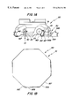
- FIG. 1A shows an embodiment of a milling cutter according to the present invention, in a side view
- FIG. 1B schematically shows two octagonal cutting inserts in sequence
- FIG. 2A shows a plan view of a cutting insert of the milling cutter of FIG. 1;
- FIG. 2B shows a section along line II—II in FIG. 2A;
- FIG. 2C shows an insert in a side view
- FIG. 2D shows a magnified portion of a lower corner of the insert in FIG. 2B
- FIG. 3A shows a plan view of a wiper insert according to the present invention
- FIG. 3B shows a section along line III—III in FIG. 3A;
- FIG. 3C shows the wiper insert in a side view
- FIG. 3D shows the wiper insert in a bottom view.
- FIG. 1A a milling cutter 30 according to the present invention, including a tool holder 31 and cutting inserts 10 and 50 .
- the holder 30 is a milling cutter body which has a number of pockets 32 for receiving cutting inserts.
- Each pocket comprises a substantially planar base 40 and two shoulders (only one shoulder 42 being visible). The shoulders are substantially perpendicular to each other.
- Each shoulder includes a first surface, provided to abut a corresponding first portion 13 a of the insert 10 or 50 .
- a threaded boring is provided in the vicinity of the pocket 32 so as to receive a fastening screw 33 to force the insert towards the shoulders and the base, via a radially outer part of the screw head.
- the screw 33 is partially unscrewed until the cutting insert can be pulled by hand radially outwardly and the insert may be rotated by an increment corresponding to 45° counter-clockwise, so that a fresh secondary cutting edge 16 E comes into position. Then the insert is pushed into the pocket and the screw is tightened again.
- the edge 16 D is preferably passive and does not cut during milling.
- at least one wiper insert 50 according to the present invention is inserted into the milling cutter 30 .
- the wiper insert 50 fits into any of the pockets 32 as described above in connection with the insert 10 .
- FIG. 1B schematically shows two octagonal cutting 10 , 50 inserts in sequence, i.e. each insert profile is taken at the same position at the periphery of the cutter.
- the cutting insert 10 depicted in FIGS. 2A to 2 D has a generally octagonal basic shape and includes an upper face 11 , a lower face 12 and an edge face 13 generally interconnecting the upper and lower faces 11 and 12 .
- the cutting insert 10 has a positive geometry, i.e., an upper portion 13 a of the edge face defines a clearance face and forms an acute angle with the upper face 11 , the latter being a rake face.
- the upper face 11 includes a chip upsetting face located at the periphery of the insert 10 .
- the upper face 11 furthermore, includes a chip face 15 sloping inwardly and downwardly from the chip upsetting face. The latter faces constitute the most peripheral part of the upper face 11 .
- the intersecting line between the chip upsetting face and the edge face 13 forms the overall cutting edge structure 16 , which is defined by eight cutting edges 16 A- 16 H.
- the chip face 15 is concavely curved and extends inwardly from the chip upsetting face and forms a transition edge 26 therewith.
- a plurality of projections or preferably depressions 25 are formed in the chip face 15 , the projections or depressions 25 being spaced apart along the transition edge 26 .
- the depressions 25 preferably intersect the transition edge and extend inwardly therefrom in a direction non-perpendicularly to the associated cutting edge 16 as said insert is viewed in plan. Each depression thereby forms, as viewed in plan, an angle in the range of 15° to 40° relative to a normal N of the associated cutting edge. The effect of such design is to minimize heat transfer from the chip to the insert.
- Respective pairs of adjacent cutting edges 16 meet to form a cutting corner 34 having an internal obtuse angle, about 135°.
- Each cutting edge is concavely curved when seen in a side view, such that the midsection of the edge is closer to the lower side 12 than are the end sections thereof.
- a ridge 28 provided at each intersection of the chip faces 15 strengthens each corner 34 and forms the chip generated at the corner 34 .
- the edge face 13 includes eight segments. An upper portion 13 a of each segment of the edge face 13 forms a clearance angle a with a plane P oriented parallel to a center axis 20 of the insert (FIG. 2 B).
- the clearance angle a is at least 20°, preferably at least 25°.
- the distance between two diametrically opposed major cutting edges 16 C and 16 G for example is depicted by numeral L 1 in FIG. 2 A. The distance L 1 is the same for all combinations of diametrically opposed major cutting edges.
- the eight, planar edge surfaces 13 taper (converge) towards the lower face 12 and generally intersect at the center line 20 of the cutting insert 10 below the lower face 12 .
- Each segment of the edge face 13 is provided with an inward, downwardly facing shoulder forming a step 18 .
- the upper or first portion 13 a of the segment is located above the step 18 and has a positive geometry in order to provide the necessary clearance angle.
- a lower or second portion 13 b of the segment forms a peripheral edge of the shim 22 which is of integral one-piece construction with the upper part of the insert.
- the shim 22 forms the lower face 12 of the insert.
- Each second portion 13 b extends parallel to a respective one of the cutting edges.
- the second portion 13 b of each segment has a negative geometry, i.e. the second portion 13 b is perpendicular to the lower face 12 and thus forms no clearance angle.
- Each second portion 13 b lies radially inside of an imaginary extension E of the associated first portion. That is, the second portion 13 b of the edge surface does not need to be ground if the clearance face 13 a is ground, thereby saving energy. Furthermore the step 18 will then be sufficiently large in the radial direction to provide for a favorable control of any cracks emanating during machining.
- the step 18 thus provides a sharp inner corner 19 that constitutes an exit zone for a fracture that by a possible break of the cutting edge controls the break and leaves the lower portion of the cutting insert undamaged.
- sh is here meant that the corner is intentionally weakened by having a radius of 0 to 0.3 mm, preferably about 0.2 mm.
- the second or lower portion 13 b thus protects the tool body.
- the height h 1 of the second portion 13 b is 15-60% of the insert height h, preferably about 25%. This is possible since the anvil or shim constitutes an integral part of the cutting insert 10 , i.e. the height h 1 corresponds to the height of the integrated shim 22 . In order to achieve a good function of the cutting insert 10 it is necessary that the height h 1 does not constitute too big a part of the height h since in that case the strength of the cutting edge would be too low. That could result in fractures of the cutting edge also at small loads.
- the smallest radial distance d from the step 18 to the second portion 13 b in the plane of the lower face 12 depends on the clearance angle.
- the distance in the cross section II—II in FIG. 2A is in the interval 0.01-1.0 mm, preferably 0.1 mm.
- the second portion 13 b is about parallel with the center axis 20 .
- the step 18 forms an angle ⁇ with a line y extending perpendicular to the center axis 20 .
- the angle ⁇ is 0° to 30°, and preferably about 20°.
- Eight second portions 13 b are formed around the periphery of the shim 22 . Two adjacent ones of the second portions 13 b meet in a corner 23 at an internal obtuse angle, about 135°. The corners project radially relative to the rest of the second portions 13 b.
- the periphery of the lower part describes a path of increasing and decreasing radial distances from the center axis 20 of the insert.
- FIGS. 3A to 3 D a wiper insert 50 according to the present invention is shown having the same basic shape as the insert 10 described above and like features are depicted by like numerals hereinafter.
- the cutting insert 50 depicted in FIGS. 3A to 3 D has a generally octagonal basic shape and includes an upper face 11 , a lower face 12 and an edge face 13 generally interconnecting the upper and lower faces 11 and 12 , respectively.
- the cutting insert 50 has a positive geometry, i.e., an upper portion 13 a of the edge face defines a clearance face and forms an acute angle with the upper face 11 , the latter being a rake face.
- the upper face 11 includes a circumferential land 51 located generally at the periphery of the insert 50 (see FIG. 3 A).
- the upper face 11 furthermore includes a recess 52 defined by a star-shaped rim 53 sloping inwardly and downwardly from the land 51 to a bottom surface 54 .
- the rim 53 describes a path of a generally sinusoidal curve. The rim is provided to safeguard the insert from being thrown outwardly if the frictional force between the fastening device and the bottom 54 is overpowered by centrifugal force.
- the depth Z of the recess 52 is about 0.1 mm.
- the bottom surface 54 is provided with four markings or arrows 59 to facilitate identification of respective wiper edges 55 B- 58 B.
- the intersecting line between the land 51 and the edge face 13 forms four pairs of cutting edges 55 - 58 , each pair comprising a major cutting edge 55 A- 58 A and a wiper edge 55 B- 58 B such that every other cutting edge is a major cutting edge 55 A- 58 A joining a wiper edge 55 B- 58 B situated between two major cutting edges.
- a first distance L 2 between two diametrically opposed, parallel, wiper edges 56 B and 58 B for example, is larger than a second perpendicular distance L 3 between two diametrically opposed, main cutting edges 55 A and 57 A.
- the first distance L 2 is about 1% to 5% larger than the second distance L 3 , preferably about 1.5% larger.
- the first distance L 2 is about 0.1% to 1% larger than the distance L 1 of the insert 10 , preferably about 0.5% larger.
- the edges 55 B- 58 B are substantially straight when seen in a side view and lie in a common plane K (FIG. 3C) but are preferably somewhat curved when seen in a plan view. The radius of said curve is about 600 mm.
- An imaginary circle C inscribed in the insert 50 touches each wiper edge, i.e. each wiper edge is tangential to the circle.
- a part of each major cutting edge extends radially inside of the circle C by a distance X, FIG. 3 A.
- Locating segments 13 c connected to the upper portions 13 a are provided at a clearance angle which is larger than the clearance angle of the upper portions 13 a.
- the insert 50 is mounted to the tool body in generally the same manner as the insert 10 . However, only two of the passive locating segments 13 c connected to the wiper edges, for example 56 B and 57 B, will simultaneously bear against the shoulders of the tool body 31 .
- Passive is here meant that the segment or connected cutting edge is not in cutting position. In the position shown in FIG. 1B the major cutting edge 55 A of the wiper insert 50 is aligned with the major cutting edge 16 F of the insert 10 , i.e. they coincide with an imaginary truncated cone.
- the edge 55 B of the wiper insert By having the active wiper edge 55 B of the wiper insert extend further forwardly in the axial direction of the milling cutter as compared to the edge 16 E of the insert 10 , due to the longer distance L 2 , the edge 55 B will generate the surface in the workpiece (not shown). Furthermore by having the distance L 3 of the wiper insert shorter than the distance L 1 of the insert 10 , the edges 55 A and 16 F still can lie in a common imaginary cone.
- the recess 52 is provided to cooperate with the screw head 33 to keep the insert 50 from being thrown radially outwardly from the cutter due to centrifugal forces when in use.
- a wiper insert and a milling tool providing a very fine surface finish. Furthermore an economically favorable wiper insert having at least three wiper edges is provided.
- the wiper insert is easily mounted in the tool body since the wiper insert has a built-in cutting depth.
- the present invention provides an economical solution to the user, by having eight cutting edges in combination with wiper edges and by saving holder bodies if the insert fractures.
- the tool according to the present invention cuts in an easy manner through the workpiece metal which is especially important when a thin flange is supposed to remain connected to the work- piece of aluminum, for example.
- the inserts 10 , 50 may alternatively have hexagonal basic shapes and thus the insert 10 would provide six cutting edges and the wiper insert 50 would provide three wiper edges.
- the cutting inserts 10 , 50 are completely solid but may alternatively be provided with a through-hole intended to receive clamping screws that secure the cutting inserts to the tool holder.
Landscapes
- Engineering & Computer Science (AREA)
- Mechanical Engineering (AREA)
- Milling Processes (AREA)
Abstract
A milling cutter comprises a holder and at least two cutting inserts. Each cutting insert has a generally hexagonal or octagonal basic shape and includes at least three major cutting edges. An edge face of each insert is provided with a step defining an exit zone for a fracture. At least one of the cutting inserts is a wiper insert and alternating ones of the cutting edges of the wiper insert are major cutting edges separated by a wiper edge. A first distance of the wiper insert extending between two diametrically opposed wiper edges is larger than a second distance of the wiper insert extending between two diametrically opposed major cutting edges.
Description
The present invention relates to a wiper insert and a milling cutter.
In tools for metal cutting having indexable cutting inserts of hard and wear resistant material the cutting edges are subjected to wear and sometimes some part of or the entire cutting edge collapses. If a small insert fractures, only the cutting edge collapses without any risk for damage to the tool body. If a large insert fractures, the risk of damage to the tool body increases to an essential degree. If the cutting insert is not seated on a shim then a fracture of the insert often gives rise to damage of the tool body. To avoid such damage it is usual that the cutting insert rests on a shim of cemented carbide. A usual combination is a cutting insert having a thickness of about 5 mm and a shim having a thickness of 3-5 mm. This results in a total thickness of the cutting insert and the shim of 8-10 mm.
Rivière U.S. Pat. No. 5,147,158 shows a four-sided cutting insert having an integrated shim so as to provide a fracture zone. The cutting insert comprises an upper rake face, a lower face, and an edge clearance face interconnecting said upper and lower faces. The edge clearance face includes a step located intermediate the upper and lower faces. When the insert is in use the step defines a zone with a strain peak such that in the event of insert breakage, the propagation of the crack will be guided to the area of the step. The portion of the insert located below the step remains intact and thus protects the tool body.
Tsujimura et al. U.S. Pat. No. 4,966,500 shows a milling cutter having octagonal or hexagonal cutting inserts. Each cutting insert has a segmented (non-linear) major cutting edge, an end cutting edge and a radially inner cutting edge. The radially inner cutting edge is supposed to cut during coring of the work piece. The known insert lacks fracture zones so as to prevent an insert breakage from transferring into the seat or shim. Furthermore the known milling cutter cannot produce very fine surface finish.
One object of the present invention is to present a wiper insert and a milling tool that overcome the disadvantages discussed above.
Another object of the present invention is to provide a wiper insert and a milling tool providing a very fine surface finish.
Still another object of the present invention is to provide an economically favorable wiper insert providing at least three wiper edges.
Still another object of the present invention is to provide a wiper insert having a built-in cutting depth.
These and other objects are realized by a cutting insert comprising an upper face, a lower face, and an edge face. An intersection between the upper face and the edge face forms six or eight cutting edges. The upper face defines a rake face, and the edge face defines a clearance face. The clearance face forms a clearance angle with a plane extending parallel to a center axis of the insert. Alternating ones of the cutting edges define major cutting edges separated by wiper edges. A first distance extending between two diametrically opposite wiper edges is larger than a second distance extending between two diametrically opposed major cutting edges. The first distance is 1% to 5% larger than the second distance.
The invention also relates to a milling cutter wherein at least two of the above described inserts are mounted in a holder.
The objects and advantages of the invention will become apparent from the following detailed description of a preferred embodiment thereof in connection with the accompanying drawings, and in which:
FIG. 1A shows an embodiment of a milling cutter according to the present invention, in a side view;
FIG. 1B schematically shows two octagonal cutting inserts in sequence;
FIG. 2A shows a plan view of a cutting insert of the milling cutter of FIG. 1;
FIG. 2B shows a section along line II—II in FIG. 2A;
FIG. 2C shows an insert in a side view;
FIG. 2D shows a magnified portion of a lower corner of the insert in FIG. 2B;
FIG. 3A shows a plan view of a wiper insert according to the present invention;
FIG. 3B shows a section along line III—III in FIG. 3A;
FIG. 3C shows the wiper insert in a side view; and
FIG. 3D shows the wiper insert in a bottom view.
In FIG. 1A is shown a milling cutter 30 according to the present invention, including a tool holder 31 and cutting inserts 10 and 50. The holder 30 is a milling cutter body which has a number of pockets 32 for receiving cutting inserts. Each pocket comprises a substantially planar base 40 and two shoulders (only one shoulder 42 being visible). The shoulders are substantially perpendicular to each other. Each shoulder includes a first surface, provided to abut a corresponding first portion 13 a of the insert 10 or 50. A threaded boring is provided in the vicinity of the pocket 32 so as to receive a fastening screw 33 to force the insert towards the shoulders and the base, via a radially outer part of the screw head. When the insert is to be indexed, the screw 33 is partially unscrewed until the cutting insert can be pulled by hand radially outwardly and the insert may be rotated by an increment corresponding to 45° counter-clockwise, so that a fresh secondary cutting edge 16E comes into position. Then the insert is pushed into the pocket and the screw is tightened again. The edge 16D is preferably passive and does not cut during milling. To provide for an excellent surface finish, at least one wiper insert 50 according to the present invention is inserted into the milling cutter 30. The wiper insert 50 fits into any of the pockets 32 as described above in connection with the insert 10. The inserts 10, 50 will be located in the holder at a setting angle Q of about 43°, to obtain a clearance angle of about 2° for the secondary cutting edge 16E of the insert 10 and about 0° for the wiper insert edge 55B. FIG. 1B schematically shows two octagonal cutting 10, 50 inserts in sequence, i.e. each insert profile is taken at the same position at the periphery of the cutter.
The cutting insert 10 depicted in FIGS. 2A to 2D has a generally octagonal basic shape and includes an upper face 11, a lower face 12 and an edge face 13 generally interconnecting the upper and lower faces 11 and 12. The cutting insert 10 has a positive geometry, i.e., an upper portion 13 a of the edge face defines a clearance face and forms an acute angle with the upper face 11, the latter being a rake face. The upper face 11 includes a chip upsetting face located at the periphery of the insert 10. The upper face 11 furthermore, includes a chip face 15 sloping inwardly and downwardly from the chip upsetting face. The latter faces constitute the most peripheral part of the upper face 11. The intersecting line between the chip upsetting face and the edge face 13 forms the overall cutting edge structure 16, which is defined by eight cutting edges 16A-16H. The chip face 15 is concavely curved and extends inwardly from the chip upsetting face and forms a transition edge 26 therewith. A plurality of projections or preferably depressions 25 are formed in the chip face 15, the projections or depressions 25 being spaced apart along the transition edge 26. The depressions 25 preferably intersect the transition edge and extend inwardly therefrom in a direction non-perpendicularly to the associated cutting edge 16 as said insert is viewed in plan. Each depression thereby forms, as viewed in plan, an angle in the range of 15° to 40° relative to a normal N of the associated cutting edge. The effect of such design is to minimize heat transfer from the chip to the insert.
Respective pairs of adjacent cutting edges 16 meet to form a cutting corner 34 having an internal obtuse angle, about 135°. Each cutting edge is concavely curved when seen in a side view, such that the midsection of the edge is closer to the lower side 12 than are the end sections thereof. A ridge 28 provided at each intersection of the chip faces 15 strengthens each corner 34 and forms the chip generated at the corner 34.
The edge face 13 includes eight segments. An upper portion 13 a of each segment of the edge face 13 forms a clearance angle a with a plane P oriented parallel to a center axis 20 of the insert (FIG. 2B). The clearance angle a is at least 20°, preferably at least 25°. The distance between two diametrically opposed major cutting edges 16C and 16G for example is depicted by numeral L1 in FIG. 2A. The distance L1 is the same for all combinations of diametrically opposed major cutting edges.
The eight, planar edge surfaces 13 taper (converge) towards the lower face 12 and generally intersect at the center line 20 of the cutting insert 10 below the lower face 12.
Each segment of the edge face 13 is provided with an inward, downwardly facing shoulder forming a step 18. The upper or first portion 13 a of the segment is located above the step 18 and has a positive geometry in order to provide the necessary clearance angle. A lower or second portion 13 b of the segment forms a peripheral edge of the shim 22 which is of integral one-piece construction with the upper part of the insert. The shim 22 forms the lower face 12 of the insert. Each second portion 13 b extends parallel to a respective one of the cutting edges. The second portion 13 b of each segment has a negative geometry, i.e. the second portion 13 b is perpendicular to the lower face 12 and thus forms no clearance angle. Each second portion 13 b lies radially inside of an imaginary extension E of the associated first portion. That is, the second portion 13 b of the edge surface does not need to be ground if the clearance face 13 a is ground, thereby saving energy. Furthermore the step 18 will then be sufficiently large in the radial direction to provide for a favorable control of any cracks emanating during machining. The step 18 thus provides a sharp inner corner 19 that constitutes an exit zone for a fracture that by a possible break of the cutting edge controls the break and leaves the lower portion of the cutting insert undamaged. By the term “sharp” is here meant that the corner is intentionally weakened by having a radius of 0 to 0.3 mm, preferably about 0.2 mm. The second or lower portion 13 b thus protects the tool body.
Directing attention to FIG. 2B and 2D the following is to be said. The height h1 of the second portion 13 b is 15-60% of the insert height h, preferably about 25%. This is possible since the anvil or shim constitutes an integral part of the cutting insert 10, i.e. the height h1 corresponds to the height of the integrated shim 22. In order to achieve a good function of the cutting insert 10 it is necessary that the height h1 does not constitute too big a part of the height h since in that case the strength of the cutting edge would be too low. That could result in fractures of the cutting edge also at small loads. The smallest radial distance d from the step 18 to the second portion 13 b in the plane of the lower face 12 depends on the clearance angle. The distance in the cross section II—II in FIG. 2A, is in the interval 0.01-1.0 mm, preferably 0.1 mm.
The second portion 13 b is about parallel with the center axis 20. The step 18 forms an angle δ with a line y extending perpendicular to the center axis 20. The angle δ is 0° to 30°, and preferably about 20°.
Eight second portions 13 b are formed around the periphery of the shim 22. Two adjacent ones of the second portions 13 b meet in a corner 23 at an internal obtuse angle, about 135°. The corners project radially relative to the rest of the second portions 13 b. The periphery of the lower part describes a path of increasing and decreasing radial distances from the center axis 20 of the insert.
Turning now to FIGS. 3A to 3D a wiper insert 50 according to the present invention is shown having the same basic shape as the insert 10 described above and like features are depicted by like numerals hereinafter. The cutting insert 50 depicted in FIGS. 3A to 3D has a generally octagonal basic shape and includes an upper face 11, a lower face 12 and an edge face 13 generally interconnecting the upper and lower faces 11 and 12, respectively. The cutting insert 50 has a positive geometry, i.e., an upper portion 13 a of the edge face defines a clearance face and forms an acute angle with the upper face 11, the latter being a rake face. The upper face 11 includes a circumferential land 51 located generally at the periphery of the insert 50 (see FIG. 3A). The upper face 11 furthermore includes a recess 52 defined by a star-shaped rim 53 sloping inwardly and downwardly from the land 51 to a bottom surface 54. The rim 53 describes a path of a generally sinusoidal curve. The rim is provided to safeguard the insert from being thrown outwardly if the frictional force between the fastening device and the bottom 54 is overpowered by centrifugal force. The depth Z of the recess 52 is about 0.1 mm. The bottom surface 54 is provided with four markings or arrows 59 to facilitate identification of respective wiper edges 55B-58B. That is, the intersecting line between the land 51 and the edge face 13 forms four pairs of cutting edges 55-58, each pair comprising a major cutting edge 55A-58A and a wiper edge 55B-58B such that every other cutting edge is a major cutting edge 55A-58A joining a wiper edge 55B-58B situated between two major cutting edges. A first distance L2 between two diametrically opposed, parallel, wiper edges 56B and 58B for example, is larger than a second perpendicular distance L3 between two diametrically opposed, main cutting edges 55A and 57A. The first distance L2 is about 1% to 5% larger than the second distance L3, preferably about 1.5% larger. The first distance L2 is about 0.1% to 1% larger than the distance L1 of the insert 10, preferably about 0.5% larger. The edges 55B-58B are substantially straight when seen in a side view and lie in a common plane K (FIG. 3C) but are preferably somewhat curved when seen in a plan view. The radius of said curve is about 600 mm. An imaginary circle C inscribed in the insert 50 touches each wiper edge, i.e. each wiper edge is tangential to the circle. A part of each major cutting edge extends radially inside of the circle C by a distance X, FIG. 3A. Locating segments 13 c connected to the upper portions 13 a are provided at a clearance angle which is larger than the clearance angle of the upper portions 13 a.
The insert 50 is mounted to the tool body in generally the same manner as the insert 10. However, only two of the passive locating segments 13 c connected to the wiper edges, for example 56B and 57B, will simultaneously bear against the shoulders of the tool body 31. By the term “passive” is here meant that the segment or connected cutting edge is not in cutting position. In the position shown in FIG. 1B the major cutting edge 55A of the wiper insert 50 is aligned with the major cutting edge 16F of the insert 10, i.e. they coincide with an imaginary truncated cone. By having the active wiper edge 55B of the wiper insert extend further forwardly in the axial direction of the milling cutter as compared to the edge 16E of the insert 10, due to the longer distance L2, the edge 55B will generate the surface in the workpiece (not shown). Furthermore by having the distance L3 of the wiper insert shorter than the distance L1 of the insert 10, the edges 55A and 16F still can lie in a common imaginary cone.
The recess 52 is provided to cooperate with the screw head 33 to keep the insert 50 from being thrown radially outwardly from the cutter due to centrifugal forces when in use.
By applying the teachings of the present invention, there are provided a wiper insert and a milling tool providing a very fine surface finish. Furthermore an economically favorable wiper insert having at least three wiper edges is provided. In addition, the wiper insert is easily mounted in the tool body since the wiper insert has a built-in cutting depth. By providing the cutting insert 10, 50 with an integral shim, defined by a sharp corner, the possible cracks will be stopped from propagating into the holder body. The present invention provides an economical solution to the user, by having eight cutting edges in combination with wiper edges and by saving holder bodies if the insert fractures. In addition, the tool according to the present invention cuts in an easy manner through the workpiece metal which is especially important when a thin flange is supposed to remain connected to the work- piece of aluminum, for example.
Although the present invention has been described in connection with a preferred embodiment thereof, it will be appreciated by those skilled in the art that additions, deletions, modifications, and substitutions not specifically described may be made without departing from the scope of the invention as defined in the appended claims. For instance, the inserts 10, 50 may alternatively have hexagonal basic shapes and thus the insert 10 would provide six cutting edges and the wiper insert 50 would provide three wiper edges. Furthermore, in the disclosed embodiment the cutting inserts 10, 50 are completely solid but may alternatively be provided with a through-hole intended to receive clamping screws that secure the cutting inserts to the tool holder.
Claims (12)
1. A cutting insert comprising an upper face, a lower face, and an edge face; an intersection between the upper face and the edge face forming an even number of from six to eight cutting edges; the upper face defining a rake face; the edge face defining a clearance face and forming a clearance angle with a plane extending parallel to a center axis of the insert; the cutting edges including major cutting edges and wiper edges, each wiper edge disposed between two successive major cutting edges; each major cutting edge being disposed opposite, and parallel to, another of the major cutting edges; each wiper edge disposed opposite, and parallel to, another of the wiper edges; a first perpendicular distance extending between each pair of diametrically opposite wiper edges being 1% to 5% larger than a second perpendicular distance extending between each pair of diametrically opposed major cutting edges.
2. The cutting insert according to claim 1, wherein the edge face is provided with a step defining an exit zone for a fracture.
3. The cutting insert according to claim 2 wherein a distance extending from a center line of the cutting insert to the periphery of the cutting insert perpendicular to the center axis is smaller below the step than above the step, a distance from the lower face to the step being 15-60% of a distance from the lower face to the cutting edge, the step defining an exit zone for a fracture radially inside the clearance face.
4. The cutting insert according to claim 1 wherein a part of each major cutting edge extends radially inside of an imaginary circle which is inscribed in the insert and to which each wiper edge is tangentially arranged.
5. The cutting insert according to claim 1 wherein the upper face includes a land located generally at the periphery of the cutting insert, the upper face including a recess defined by a star-shaped rim sloping inwardly and downwardly from the land to a bottom surface, a depth of the recess being about 0.1 mm, an intersecting line between the land and the edge face forming four pairs of cutting edges, each pair comprising one of the major cutting edges and one of the wiper edges.
6. A milling cutter comprising a holder and at least two cutting inserts, the holder defining an axis of rotation and including an axially forward end, the cutting inserts mounted at the forward end in circumferentially spaced-apart relationship; each insert including an upper face, a lower face, and an edge face; an intersection between the upper face and the edge face forming an even number of from six to eight cutting edges; the upper face defining a rake face; the edge face defining a clearance face and forming a clearance angle with a plane extending parallel to a center axis of the respective insert; one of the inserts defining a main insert, and another of the inserts defining a wiper inset;
wherein each cutting edge of the main insert being disposed opposite and parallel to another of the cutting edges of the main insert and spaced therefrom by a first distance;
the cutting edges of the wiper insert including major cutting edges and wiper edges, each wiper edge disposed between two successive major cutting edges; each wiper edge disposed opposite, and parallel to, another of the wiper edges and spaced therefrom by a second distance; each major cutting edge disposed opposite and parallel to another of the major cutting edges and spaced therefrom by a third distance, the second distance being 1% to 5% larger than the third distance and larger than the first distance; wherein one of the cutting edges of the main insert constitutes an active cutting edge, and one of the wiper edges of the wiper insert extends farther axially forwardly than the active cutting edge.
7. The milling cutter according to claim 6 wherein the edge face is provided with a step defining an exit zone for a fracture.
8. The milling cutter according to claim 6 wherein a part of each major cutting edge extends radially inside of an imaginary circle which is inscribed in the insert and to which each wiper edge is tangentially arranged.
9. The milling cutter according to claim 6 wherein the upper face of each wiper insert includes a land located generally at the periphery of the respective wiper insert, the upper face of each wiper insert including a recess defined by a star-shaped rim sloping inwardly and downwardly from the land to a bottom surface, a depth of the recess being about 0.1 mm, an intersecting line between the land and the edge face forming four pairs of cutting edges, each pair comprising one of the major cutting edges and one of the wiper edges.
10. The milling cutter according to claim 6 wherein a distance extending from a center line of the cutting insert to the periphery of the cutting insert perpendicular to the center axis line is smaller below the step than above the step, a distance from the lower face to the step being 15-60% of a distance from the lower face to the cutting edge, the step defining an exit zone for a fracture radially inside the clearance face.
11. A cutting insert comprising an upper face, a lower face, and an edge face; an intersection between the upper face and the edge face forming an even number of cutting edges, the even number being from six to eight, the upper face defining a rake face; the edge face defining a clearance face and forming a clearance angle with a plane extending parallel to a center axis of the insert; the cutting edges including major cutting edges and wiper edges, each wiper edge disposed between two successive major cutting edges; each major cutting edge being disposed opposite, and parallel to, another of the major cutting edges; each wiper edge disposed diametrically opposite, and parallel to, another of the wiper edges; a first perpendicular distance extending between each pair of diametrically opposite wiper edges being 1% to 5% larger than a second perpendicular distance extending between each pair of diametrically opposed major cutting edges; wherein the upper face includes a land located generally at the periphery of the cutting insert; the upper face including a recess defined by a star-shaped rim sloping inwardly and downwardly from the land to a bottom surface; a depth of the recess being about 0.1 mm.
12. A milling cutter comprising a holder and at least two cutting inserts, each insert including an upper face, a lower face, and an edge face; an intersection between the upper face and the edge face forming four pairs of cutting edges, the upper face defining a rake face; the edge face defining a clearance face and forming a clearance angle with a plane extending parallel to a center axis of the respective insert; the cutting edges of at least one of the cutting inserts including major cutting edges and wiper edges, each wiper edge disposed between two successive major cutting edges; each major cutting edge being disposed opposite, and parallel to, another of the major cutting edges; each wiper edge disposed opposite, and parallel to, another of the wiper edges; a first perpendicular distance extending between two diametrically opposite wiper edges being 1% to 5% larger than a second perpendicular distance between two diametrically opposed major cutting edges; the at least one cutting insert which includes major cutting edges and wiper edges constituting at least one wiper insert; wherein the upper face of each wiper insert includes a land located generally at the periphery thereof; the upper face of each wiper insert including a recess defined by a star-shaped rim sloping inwardly and downwardly from the land to a bottom surface; a depth of the recess being about 0.1 mm; an intersecting line between the land and the edge face of each wiper insert forming the four pairs of cutting edges, each pair comprising a major cutting edge and a wiper edge.
Applications Claiming Priority (2)
| Application Number | Priority Date | Filing Date | Title |
|---|---|---|---|
| SE9800400 | 1998-02-12 | ||
| SE9800400A SE518839C2 (en) | 1998-02-12 | 1998-02-12 | Cutting tools and cutting tools |
Publications (1)
| Publication Number | Publication Date |
|---|---|
| US6254316B1 true US6254316B1 (en) | 2001-07-03 |
Family
ID=20410148
Family Applications (1)
| Application Number | Title | Priority Date | Filing Date |
|---|---|---|---|
| US09/245,839 Expired - Lifetime US6254316B1 (en) | 1998-02-12 | 1999-02-08 | Cutting tool and cutting insert |
Country Status (7)
| Country | Link |
|---|---|
| US (1) | US6254316B1 (en) |
| EP (1) | EP0936015B1 (en) |
| JP (1) | JPH11262810A (en) |
| KR (1) | KR100577671B1 (en) |
| CN (1) | CN1116950C (en) |
| DE (1) | DE69903204T2 (en) |
| SE (1) | SE518839C2 (en) |
Cited By (20)
| Publication number | Priority date | Publication date | Assignee | Title |
|---|---|---|---|---|
| US20030086766A1 (en) * | 2001-11-08 | 2003-05-08 | Andras Linn R | Dimpled insert with retaining clamp |
| US6607335B2 (en) * | 1999-04-29 | 2003-08-19 | Iscar, Ltd. | Cutting tool assembly and cutting insert therefor |
| US6802676B2 (en) * | 2001-03-02 | 2004-10-12 | Valenite Llc | Milling insert |
| US20050084353A1 (en) * | 2003-10-20 | 2005-04-21 | Iscar, Ltd. | Deburring tool and cutting insert therefor |
| USD519533S1 (en) * | 2004-04-19 | 2006-04-25 | Nubius Gmbh Praezisionswerkzeuge | Milling tools |
| US7090444B1 (en) | 2005-06-13 | 2006-08-15 | Kennametal Inc. | Helical cutting insert with axial clearance slash |
| US20060280567A1 (en) * | 2005-06-13 | 2006-12-14 | Craig Karen A | Helical cutting insert with progressive cutting edge |
| US20080260475A1 (en) * | 2005-07-20 | 2008-10-23 | Bodewig Frank | Surface milling cutter with cutting inserts, a tool for holding a cutting insert with a cutting insert and method of machining a workpiece with a surface milling cutter holding cutting inserts |
| US20090238650A1 (en) * | 2005-12-05 | 2009-09-24 | Seco Tools Ab | tool |
| US20100111619A1 (en) * | 2007-04-01 | 2010-05-06 | Assaf Ballas | Cutting Insert |
| CN101090791B (en) * | 2004-12-27 | 2010-06-16 | 伊斯卡有限公司 | Deburring tool |
| US20150202791A1 (en) * | 2014-01-22 | 2015-07-23 | Shinmax Industry Co., Ltd. | Four-Edge Blade and Cutter Head Assembly of a Wood Planing Machine |
| US20160175946A1 (en) * | 2014-12-18 | 2016-06-23 | Dmg Mori Co., Ltd. | Milling Cutter and Machining Method Using the Same |
| USD760307S1 (en) * | 2014-05-12 | 2016-06-28 | Sumitomo Electric Hardmetal Corp. | Cutting work body |
| USD760308S1 (en) * | 2014-09-26 | 2016-06-28 | Kennametal India Limited | Cutting insert with flower-shaped seating area |
| US20170225243A1 (en) * | 2014-03-27 | 2017-08-10 | Tungaloy Corporation | Cutting insert, body for the cutting insert, and cutting tool |
| JP2020044586A (en) * | 2018-09-14 | 2020-03-26 | 株式会社タンガロイ | Cutting insert and cutting tool |
| US11325196B2 (en) | 2019-07-05 | 2022-05-10 | Kennametal India Limited | Double-sided, polygonal cutting insert with alternating concave and convex cutting edges |
| US11383310B2 (en) * | 2019-12-13 | 2022-07-12 | Tungaloy Corporation | Cutting insert |
| US11453064B2 (en) | 2019-09-05 | 2022-09-27 | Kennametal Inc. | Cutting insert and cutting tool |
Families Citing this family (21)
| Publication number | Priority date | Publication date | Assignee | Title |
|---|---|---|---|---|
| SE518839C2 (en) * | 1998-02-12 | 2002-11-26 | Seco Tools Ab | Cutting tools and cutting tools |
| DE10162132B4 (en) * | 2001-12-18 | 2006-02-23 | Kennametal Inc. | cutting board |
| IL153938A0 (en) * | 2003-01-14 | 2003-07-31 | Iscar Ltd | Cutting insert and milling cutter |
| IL160223A (en) * | 2004-02-04 | 2008-11-26 | Carol Smilovici | Double-sided cutting insert and milling cutter |
| IL165620A (en) * | 2004-12-07 | 2009-05-04 | Iscar Ltd | Milling cutter |
| SE529150C2 (en) * | 2005-02-22 | 2007-05-15 | Seco Tools Ab | Metal cutting insert for turning operations has nose cutting edge having smaller chamfer angle in cross-section than chamfer angle in cross-section away from nose cutting edge |
| JP2008023660A (en) * | 2006-07-21 | 2008-02-07 | Mitsubishi Materials Corp | Cutting insert and cutting tool |
| CN102046313B (en) * | 2008-06-26 | 2013-03-20 | 塞科机床公司 | Family of cutting inserts, milling cutting tool, and cutting insert |
| SE0900286A1 (en) | 2009-03-06 | 2010-07-27 | Seco Tools Ab | Cut with recessed cutting support surface and cutting tools |
| SE534506C2 (en) * | 2009-04-30 | 2011-09-13 | Seco Tools Ab | Cutting tool and a cutting holder for a cutting tool |
| DE102009038133A1 (en) * | 2009-08-13 | 2011-02-17 | Komet Group Gmbh | Milling tool, in particular thread milling tool |
| CN101811204B (en) * | 2009-08-14 | 2013-03-20 | 哈尔滨量具刃具集团有限责任公司 | Large-feeding wavy-edge milling blade and cutter body mounting structure |
| IL201722A (en) * | 2009-10-22 | 2014-05-28 | Iscar Ltd | Milling cutter |
| EP2492035B1 (en) * | 2011-02-24 | 2016-01-13 | Seco Tools AB | Octagonal cutting insert having edge portion with variable wedge angle, and cutting tool |
| CN102500806A (en) * | 2011-10-26 | 2012-06-20 | 株洲钻石切削刀具股份有限公司 | Indexible circular milling insert and milling tool |
| JP2016168628A (en) * | 2013-07-22 | 2016-09-23 | 株式会社タンガロイ | Cutting insert |
| CN105436589B (en) * | 2015-12-18 | 2018-05-15 | 株洲钻石切削刀具股份有限公司 | A kind of milling cutter with cooling structure |
| TWI825040B (en) * | 2017-11-30 | 2023-12-11 | 以色列商艾斯卡公司 | Single-sided three-way indexable milling insert, tool holder and insert mill comprising the insert and the tool holder |
| WO2019135290A1 (en) * | 2018-01-08 | 2019-07-11 | オーエスジー株式会社 | Insert and body |
| JP6868200B1 (en) * | 2019-12-13 | 2021-05-12 | 株式会社タンガロイ | Cutting insert |
| US11850670B2 (en) * | 2020-04-24 | 2023-12-26 | Kennametal India Ltd. | Milling cutting inserts |
Citations (15)
| Publication number | Priority date | Publication date | Assignee | Title |
|---|---|---|---|---|
| US4556345A (en) * | 1983-02-01 | 1985-12-03 | Fried. Krupp Gesellschaft Mit Beschrankter Haftung | Multi-cornered reversible cutting-plate |
| US4616962A (en) * | 1984-04-28 | 1986-10-14 | Mitsubishi Kinzoku Kabushiki Kaisha | Cutter insert |
| US4954021A (en) * | 1988-06-10 | 1990-09-04 | Mitsubishi Metal Corporation | Inserted rotary cutter |
| US4966500A (en) | 1987-09-16 | 1990-10-30 | Mitsubishi Kinzoku Kabushiki Kaisha | Face milling cutter with cutter inserts |
| US4971483A (en) * | 1988-09-24 | 1990-11-20 | Mapal Fabrik Fur Prazisionswerkzeuge Dr. Kress Kg | Cutter plate for precision working, especially of holes |
| US4995767A (en) * | 1988-10-11 | 1991-02-26 | North American Products, Corp. | Face milling cutter with indexable inserts |
| US5074720A (en) * | 1989-06-22 | 1991-12-24 | Seco Tools Ab | Cutting insert for chip forming machining |
| US5147158A (en) | 1990-05-22 | 1992-09-15 | Seco Tools Ab | Cutting insert |
| USD377801S (en) * | 1995-06-22 | 1997-02-04 | Mapal Fabrik Fur Prazisionswerkzeuge Dr. Kress Kg | Six-edged cutting tool |
| US5611649A (en) * | 1994-06-18 | 1997-03-18 | Camco Drilling Group Limited | Elements faced with superhard material |
| US5827016A (en) * | 1996-06-20 | 1998-10-27 | Seco Tools Ab | Octagonal milling insert with anti-rattle configuration and strengthened cutting edges |
| US5876160A (en) * | 1996-08-21 | 1999-03-02 | Ingersoll Cutting Tool Company | Milling with insert having cutting-edge land of width increasing with depth of cut |
| US5915889A (en) * | 1996-07-11 | 1999-06-29 | Mapal Fabrik Fur Prazisionswerkzeuge Dr. Kress Kg | Cutting tip developed as a polygon with a chip breaker |
| US6079912A (en) * | 1996-01-31 | 2000-06-27 | Widia Gmbh | Cutter insert for roughing and finishing |
| US6116824A (en) * | 1998-03-10 | 2000-09-12 | Seco Tools Ab | Cutting insert for a milling cutter, and a method of preventing accidental dislodgement of cutting inserts |
Family Cites Families (5)
| Publication number | Priority date | Publication date | Assignee | Title |
|---|---|---|---|---|
| US1460029A (en) * | 1922-10-30 | 1923-06-26 | Mattson Julius | Milling-machine cutter |
| SU1046030A1 (en) * | 1982-07-12 | 1983-10-07 | Ордена Трудового Красного Знамени Ленинградский Институт Точной Механики И Оптики | Base plate |
| US5672031A (en) * | 1995-05-12 | 1997-09-30 | Kennametal Inc. | Milling cutter |
| SE518839C2 (en) * | 1998-02-12 | 2002-11-26 | Seco Tools Ab | Cutting tools and cutting tools |
| JP4369980B2 (en) * | 2007-03-30 | 2009-11-25 | 日本特殊陶業株式会社 | Spark plug for internal combustion engine |
-
1998
- 1998-02-12 SE SE9800400A patent/SE518839C2/en not_active IP Right Cessation
-
1999
- 1999-01-22 EP EP99850008A patent/EP0936015B1/en not_active Expired - Lifetime
- 1999-01-22 DE DE69903204T patent/DE69903204T2/en not_active Expired - Lifetime
- 1999-02-02 JP JP11024701A patent/JPH11262810A/en active Pending
- 1999-02-02 CN CN99100561A patent/CN1116950C/en not_active Expired - Lifetime
- 1999-02-08 US US09/245,839 patent/US6254316B1/en not_active Expired - Lifetime
- 1999-02-11 KR KR1019990004912A patent/KR100577671B1/en not_active Expired - Lifetime
Patent Citations (15)
| Publication number | Priority date | Publication date | Assignee | Title |
|---|---|---|---|---|
| US4556345A (en) * | 1983-02-01 | 1985-12-03 | Fried. Krupp Gesellschaft Mit Beschrankter Haftung | Multi-cornered reversible cutting-plate |
| US4616962A (en) * | 1984-04-28 | 1986-10-14 | Mitsubishi Kinzoku Kabushiki Kaisha | Cutter insert |
| US4966500A (en) | 1987-09-16 | 1990-10-30 | Mitsubishi Kinzoku Kabushiki Kaisha | Face milling cutter with cutter inserts |
| US4954021A (en) * | 1988-06-10 | 1990-09-04 | Mitsubishi Metal Corporation | Inserted rotary cutter |
| US4971483A (en) * | 1988-09-24 | 1990-11-20 | Mapal Fabrik Fur Prazisionswerkzeuge Dr. Kress Kg | Cutter plate for precision working, especially of holes |
| US4995767A (en) * | 1988-10-11 | 1991-02-26 | North American Products, Corp. | Face milling cutter with indexable inserts |
| US5074720A (en) * | 1989-06-22 | 1991-12-24 | Seco Tools Ab | Cutting insert for chip forming machining |
| US5147158A (en) | 1990-05-22 | 1992-09-15 | Seco Tools Ab | Cutting insert |
| US5611649A (en) * | 1994-06-18 | 1997-03-18 | Camco Drilling Group Limited | Elements faced with superhard material |
| USD377801S (en) * | 1995-06-22 | 1997-02-04 | Mapal Fabrik Fur Prazisionswerkzeuge Dr. Kress Kg | Six-edged cutting tool |
| US6079912A (en) * | 1996-01-31 | 2000-06-27 | Widia Gmbh | Cutter insert for roughing and finishing |
| US5827016A (en) * | 1996-06-20 | 1998-10-27 | Seco Tools Ab | Octagonal milling insert with anti-rattle configuration and strengthened cutting edges |
| US5915889A (en) * | 1996-07-11 | 1999-06-29 | Mapal Fabrik Fur Prazisionswerkzeuge Dr. Kress Kg | Cutting tip developed as a polygon with a chip breaker |
| US5876160A (en) * | 1996-08-21 | 1999-03-02 | Ingersoll Cutting Tool Company | Milling with insert having cutting-edge land of width increasing with depth of cut |
| US6116824A (en) * | 1998-03-10 | 2000-09-12 | Seco Tools Ab | Cutting insert for a milling cutter, and a method of preventing accidental dislodgement of cutting inserts |
Cited By (32)
| Publication number | Priority date | Publication date | Assignee | Title |
|---|---|---|---|---|
| US6607335B2 (en) * | 1999-04-29 | 2003-08-19 | Iscar, Ltd. | Cutting tool assembly and cutting insert therefor |
| US6802676B2 (en) * | 2001-03-02 | 2004-10-12 | Valenite Llc | Milling insert |
| US7073986B2 (en) * | 2001-11-08 | 2006-07-11 | Kennametal Inc. | Dimpled insert with retaining clamp |
| US20030086766A1 (en) * | 2001-11-08 | 2003-05-08 | Andras Linn R | Dimpled insert with retaining clamp |
| USRE45536E1 (en) * | 2001-11-08 | 2015-06-02 | Kennametal Inc. | Dimpled insert with retaining clamp |
| US7217070B2 (en) * | 2003-10-20 | 2007-05-15 | Iscar Ltd. | Deburring tool and cutting insert therefor |
| US20050084353A1 (en) * | 2003-10-20 | 2005-04-21 | Iscar, Ltd. | Deburring tool and cutting insert therefor |
| USD519533S1 (en) * | 2004-04-19 | 2006-04-25 | Nubius Gmbh Praezisionswerkzeuge | Milling tools |
| CN101090791B (en) * | 2004-12-27 | 2010-06-16 | 伊斯卡有限公司 | Deburring tool |
| US7090444B1 (en) | 2005-06-13 | 2006-08-15 | Kennametal Inc. | Helical cutting insert with axial clearance slash |
| US20060280567A1 (en) * | 2005-06-13 | 2006-12-14 | Craig Karen A | Helical cutting insert with progressive cutting edge |
| US20070086865A1 (en) * | 2005-06-13 | 2007-04-19 | Kennametal Inc. | Helical cutting insert with progressive cutting edge |
| US7229236B2 (en) | 2005-06-13 | 2007-06-12 | Kennametal Inc. | Helical cutting insert with progressive cutting edge |
| US7396192B2 (en) | 2005-06-13 | 2008-07-08 | Kennametal Inc. | Helical cutting insert with progressive cutting edge |
| US20110236147A1 (en) * | 2005-07-20 | 2011-09-29 | Bodewig Frank | Surface milling cutter with cutting inserts, a tool for holding a cutting insert with a cutting insert and method of machining a workpiece with a surface milling cutter holding cutting inserts |
| US20080260475A1 (en) * | 2005-07-20 | 2008-10-23 | Bodewig Frank | Surface milling cutter with cutting inserts, a tool for holding a cutting insert with a cutting insert and method of machining a workpiece with a surface milling cutter holding cutting inserts |
| US20090238650A1 (en) * | 2005-12-05 | 2009-09-24 | Seco Tools Ab | tool |
| US8641330B2 (en) * | 2005-12-05 | 2014-02-04 | Seco Tools Ab | Tool |
| US8231311B2 (en) * | 2007-04-01 | 2012-07-31 | Iscar, Ltd. | Cutting insert |
| US20100111619A1 (en) * | 2007-04-01 | 2010-05-06 | Assaf Ballas | Cutting Insert |
| US20150202791A1 (en) * | 2014-01-22 | 2015-07-23 | Shinmax Industry Co., Ltd. | Four-Edge Blade and Cutter Head Assembly of a Wood Planing Machine |
| US20170225243A1 (en) * | 2014-03-27 | 2017-08-10 | Tungaloy Corporation | Cutting insert, body for the cutting insert, and cutting tool |
| US10010950B2 (en) * | 2014-03-27 | 2018-07-03 | Tungaloy Corporation | Cutting insert having a variable-width land and cutting tool |
| USD760307S1 (en) * | 2014-05-12 | 2016-06-28 | Sumitomo Electric Hardmetal Corp. | Cutting work body |
| USD760308S1 (en) * | 2014-09-26 | 2016-06-28 | Kennametal India Limited | Cutting insert with flower-shaped seating area |
| US20160175946A1 (en) * | 2014-12-18 | 2016-06-23 | Dmg Mori Co., Ltd. | Milling Cutter and Machining Method Using the Same |
| US10029318B2 (en) * | 2014-12-18 | 2018-07-24 | Dmg Mori Co., Ltd. | Milling cutter and machining method using the same |
| JP2020044586A (en) * | 2018-09-14 | 2020-03-26 | 株式会社タンガロイ | Cutting insert and cutting tool |
| US11325196B2 (en) | 2019-07-05 | 2022-05-10 | Kennametal India Limited | Double-sided, polygonal cutting insert with alternating concave and convex cutting edges |
| US11453064B2 (en) | 2019-09-05 | 2022-09-27 | Kennametal Inc. | Cutting insert and cutting tool |
| US11772168B2 (en) | 2019-09-05 | 2023-10-03 | Kennametal Inc. | Cutting insert and cutting tool |
| US11383310B2 (en) * | 2019-12-13 | 2022-07-12 | Tungaloy Corporation | Cutting insert |
Also Published As
| Publication number | Publication date |
|---|---|
| CN1225858A (en) | 1999-08-18 |
| DE69903204D1 (en) | 2002-11-07 |
| JPH11262810A (en) | 1999-09-28 |
| SE9800400L (en) | 1999-08-13 |
| KR100577671B1 (en) | 2006-05-09 |
| EP0936015A1 (en) | 1999-08-18 |
| SE518839C2 (en) | 2002-11-26 |
| DE69903204T2 (en) | 2003-07-10 |
| EP0936015B1 (en) | 2002-10-02 |
| KR19990072603A (en) | 1999-09-27 |
| SE9800400D0 (en) | 1998-02-12 |
| CN1116950C (en) | 2003-08-06 |
Similar Documents
| Publication | Publication Date | Title |
|---|---|---|
| US6254316B1 (en) | Cutting tool and cutting insert | |
| US5827016A (en) | Octagonal milling insert with anti-rattle configuration and strengthened cutting edges | |
| US6116824A (en) | Cutting insert for a milling cutter, and a method of preventing accidental dislodgement of cutting inserts | |
| EP2119520B1 (en) | Milling insert | |
| EP0833713B1 (en) | Cutting tool and method | |
| EP2308623B1 (en) | Milling tool for chip removing machining having a shim plate | |
| US6004081A (en) | Tool for metal cutting | |
| EP1401603B1 (en) | Sintered cutting insert having center hole for clamp screw | |
| US4632607A (en) | Indexable cutting insert | |
| EP1791671B1 (en) | A milling tool, a cutting insert for milling tool as well as a solid milling tool | |
| US5147158A (en) | Cutting insert | |
| US5741095A (en) | Cutting tool and insert therefor | |
| EP0462954B1 (en) | Ball end mill and throw away insert for such end mill | |
| JP7055963B2 (en) | Cutting tool bodies, cutting inserts and cutting tools | |
| US6712562B2 (en) | Milling tool and milling inserts having impact protection for main cutting edges | |
| JPS6119859Y2 (en) | ||
| CA2045365A1 (en) | Ball end mill and throw away insert for such end mill |
Legal Events
| Date | Code | Title | Description |
|---|---|---|---|
| AS | Assignment |
Owner name: SECO TOOLS AB, SWEDEN Free format text: ASSIGNMENT OF ASSIGNORS INTEREST;ASSIGNOR:STRAND, BENGT;REEL/FRAME:009909/0318 Effective date: 19990319 |
|
| STCF | Information on status: patent grant |
Free format text: PATENTED CASE |
|
| FPAY | Fee payment |
Year of fee payment: 4 |
|
| FPAY | Fee payment |
Year of fee payment: 8 |
|
| FPAY | Fee payment |
Year of fee payment: 12 |