US6254237B1 - Multi-pixel microlens illumination in electronic display projector - Google Patents
Multi-pixel microlens illumination in electronic display projector Download PDFInfo
- Publication number
- US6254237B1 US6254237B1 US09/302,911 US30291199A US6254237B1 US 6254237 B1 US6254237 B1 US 6254237B1 US 30291199 A US30291199 A US 30291199A US 6254237 B1 US6254237 B1 US 6254237B1
- Authority
- US
- United States
- Prior art keywords
- color
- projector
- elements
- microlens
- array
- Prior art date
- Legal status (The legal status is an assumption and is not a legal conclusion. Google has not performed a legal analysis and makes no representation as to the accuracy of the status listed.)
- Expired - Fee Related
Links
- 238000005286 illumination Methods 0.000 title claims description 77
- 238000003491 array Methods 0.000 claims abstract description 29
- 238000000926 separation method Methods 0.000 claims description 13
- 238000003384 imaging method Methods 0.000 claims description 4
- 239000004973 liquid crystal related substance Substances 0.000 abstract description 12
- 230000003287 optical effect Effects 0.000 description 11
- 230000004075 alteration Effects 0.000 description 3
- 238000001914 filtration Methods 0.000 description 3
- 230000000007 visual effect Effects 0.000 description 3
- 230000009286 beneficial effect Effects 0.000 description 2
- 238000010586 diagram Methods 0.000 description 2
- 238000004519 manufacturing process Methods 0.000 description 2
- 229910001507 metal halide Inorganic materials 0.000 description 2
- 150000005309 metal halides Chemical class 0.000 description 2
- 230000010287 polarization Effects 0.000 description 2
- 210000001747 pupil Anatomy 0.000 description 2
- 239000006185 dispersion Substances 0.000 description 1
- 230000000694 effects Effects 0.000 description 1
- 229910052736 halogen Inorganic materials 0.000 description 1
- 150000002367 halogens Chemical class 0.000 description 1
- 239000011159 matrix material Substances 0.000 description 1
- 238000000034 method Methods 0.000 description 1
- 229910021420 polycrystalline silicon Inorganic materials 0.000 description 1
- 238000005549 size reduction Methods 0.000 description 1
- 239000010409 thin film Substances 0.000 description 1
- 229910052724 xenon Inorganic materials 0.000 description 1
- FHNFHKCVQCLJFQ-UHFFFAOYSA-N xenon atom Chemical compound [Xe] FHNFHKCVQCLJFQ-UHFFFAOYSA-N 0.000 description 1
Images


Classifications
-
- G—PHYSICS
- G02—OPTICS
- G02B—OPTICAL ELEMENTS, SYSTEMS OR APPARATUS
- G02B27/00—Optical systems or apparatus not provided for by any of the groups G02B1/00 - G02B26/00, G02B30/00
- G02B27/10—Beam splitting or combining systems
- G02B27/14—Beam splitting or combining systems operating by reflection only
- G02B27/149—Beam splitting or combining systems operating by reflection only using crossed beamsplitting surfaces, e.g. cross-dichroic cubes or X-cubes
-
- G—PHYSICS
- G02—OPTICS
- G02B—OPTICAL ELEMENTS, SYSTEMS OR APPARATUS
- G02B27/00—Optical systems or apparatus not provided for by any of the groups G02B1/00 - G02B26/00, G02B30/00
- G02B27/10—Beam splitting or combining systems
- G02B27/1006—Beam splitting or combining systems for splitting or combining different wavelengths
- G02B27/102—Beam splitting or combining systems for splitting or combining different wavelengths for generating a colour image from monochromatic image signal sources
- G02B27/1046—Beam splitting or combining systems for splitting or combining different wavelengths for generating a colour image from monochromatic image signal sources for use with transmissive spatial light modulators
- G02B27/1053—Beam splitting or combining systems for splitting or combining different wavelengths for generating a colour image from monochromatic image signal sources for use with transmissive spatial light modulators having a single light modulator for all colour channels
-
- G—PHYSICS
- G02—OPTICS
- G02B—OPTICAL ELEMENTS, SYSTEMS OR APPARATUS
- G02B27/00—Optical systems or apparatus not provided for by any of the groups G02B1/00 - G02B26/00, G02B30/00
- G02B27/10—Beam splitting or combining systems
- G02B27/14—Beam splitting or combining systems operating by reflection only
- G02B27/145—Beam splitting or combining systems operating by reflection only having sequential partially reflecting surfaces
-
- G—PHYSICS
- G02—OPTICS
- G02B—OPTICAL ELEMENTS, SYSTEMS OR APPARATUS
- G02B27/00—Optical systems or apparatus not provided for by any of the groups G02B1/00 - G02B26/00, G02B30/00
- G02B27/10—Beam splitting or combining systems
- G02B27/14—Beam splitting or combining systems operating by reflection only
- G02B27/148—Beam splitting or combining systems operating by reflection only including stacked surfaces having at least one double-pass partially reflecting surface
-
- G—PHYSICS
- G03—PHOTOGRAPHY; CINEMATOGRAPHY; ANALOGOUS TECHNIQUES USING WAVES OTHER THAN OPTICAL WAVES; ELECTROGRAPHY; HOLOGRAPHY
- G03B—APPARATUS OR ARRANGEMENTS FOR TAKING PHOTOGRAPHS OR FOR PROJECTING OR VIEWING THEM; APPARATUS OR ARRANGEMENTS EMPLOYING ANALOGOUS TECHNIQUES USING WAVES OTHER THAN OPTICAL WAVES; ACCESSORIES THEREFOR
- G03B21/00—Projectors or projection-type viewers; Accessories therefor
- G03B21/005—Projectors using an electronic spatial light modulator but not peculiar thereto
-
- H—ELECTRICITY
- H04—ELECTRIC COMMUNICATION TECHNIQUE
- H04N—PICTORIAL COMMUNICATION, e.g. TELEVISION
- H04N9/00—Details of colour television systems
- H04N9/12—Picture reproducers
- H04N9/31—Projection devices for colour picture display, e.g. using electronic spatial light modulators [ESLM]
- H04N9/3102—Projection devices for colour picture display, e.g. using electronic spatial light modulators [ESLM] using two-dimensional electronic spatial light modulators
- H04N9/3105—Projection devices for colour picture display, e.g. using electronic spatial light modulators [ESLM] using two-dimensional electronic spatial light modulators for displaying all colours simultaneously, e.g. by using two or more electronic spatial light modulators
-
- H—ELECTRICITY
- H04—ELECTRIC COMMUNICATION TECHNIQUE
- H04N—PICTORIAL COMMUNICATION, e.g. TELEVISION
- H04N9/00—Details of colour television systems
- H04N9/12—Picture reproducers
- H04N9/31—Projection devices for colour picture display, e.g. using electronic spatial light modulators [ESLM]
- H04N9/3141—Constructional details thereof
- H04N9/315—Modulator illumination systems
-
- G—PHYSICS
- G02—OPTICS
- G02B—OPTICAL ELEMENTS, SYSTEMS OR APPARATUS
- G02B3/00—Simple or compound lenses
- G02B3/0006—Arrays
- G02B3/0037—Arrays characterized by the distribution or form of lenses
- G02B3/0062—Stacked lens arrays, i.e. refractive surfaces arranged in at least two planes, without structurally separate optical elements in-between
Definitions
- the present invention relates to electronic display (e.g., LCD) projectors and, in particular, to such a projector with a microlens array that provides small angle illumination of adjacent pixels.
- LCD electronic display
- Color liquid crystal display projectors generate display images and project them onto display screens, typically for viewing by multiple persons or viewers.
- the display images may be formed by transmitting light from a high-intensity source of polychromatic or white light through an image-forming medium such as a liquid crystal display (LCD).
- LCD liquid crystal display
- U.S. Pat. No. 5,161,042 of Hamada describes a color liquid crystal display projection system that utilizes a sequence of red, green, and blue inclined dichroic color selective mirrors to form angularly color separated color component light beams without the brightness losses caused by conventional color filter mosaics.
- the separate color component light beams are directed to an array of microlenses each of which converges the light beams onto one picture element aperture of the liquid crystal display.
- a disadvantage of such a system is that the angularly color separated color component light beams would typically be implemented with relatively large color separation angles of, for example, 6 degrees per color component channel. While providing relatively efficient color-separated illumination, such large color separation angles can require that the projector projection lens arrangement have a low F-number of f2.5 or less.
- F-number is a ratio of the pupil or aperture size (e.g., along a horizontal direction) to the focal length of the lens arrangement. Projection lens arrangements with such low F-numbers can be difficult to manufacture and are susceptible to various optical aberrations that can degrade the display image quality.
- one implementation of the present invention includes a color liquid crystal display projector having a light source with a radiating element (e.g., arc or incandescent) and a liquid crystal display (LCD).
- the LCD includes an array of multiple picture elements or pixels that each have separate color component sub-pixels (e.g., red, green and blue). Multiple differently inclined dichroic mirrors angularly separate the light into light beams of different color components.
- An integrating lens array relay system has a pair of planar lens arrays that form multiple spatially separated images of the angularly-color separated light components.
- a microlens array positioned adjacent to the LCD images the spatially separated images upon the color component sub-pixels of the LCD.
- the first planar lens array receives white light and forms in the second lens array color component (i.e., red, green, and blue) images of the light source (i.e., the radiating element).
- Color component filters may optionally be positioned adjacent the second lens array to filter these color component images, rather than filtering them at the LCD as is conventional and more expensive to implement.
- the color component light source images formed in the second planar lens array match and are mapped to the color component sub-pixels of the LCD.
- Each microlens in the microlens array directs light from the multiple spatially separated images into corresponding sub-pixels of multiple ones of the pixels.
- FIG. 1 is a schematic illustration of a single panel color electronic display projector according to the present invention.
- FIG. 2 is a schematic diagram illustrating a color-separated illumination source image provided by a planar integrating lens array of a relay system.
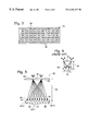
- FIG. 3 shows a top sectional view of three microlens elements in a single horizontal or row portion of a LCD microlens array.
- FIG. 4 illustrates imaging characteristics of an exemplary prior art LCD microlens element in relation to a single pixel.
- FIG. 5 is an illustration comparing extreme light rays passing through LCD microlens elements according to the present invention and passing through a model microlens element representing a scaled prior art microlens element.
- FIG. 6 shows illustrations of the relative advantages of different arrangements of spatially separated illumination in terms of the corresponding numbers of microlens elements and pixels.
- FIG. 7 is a schematic illustration of one channel of a three-path color projector according to the present invention.
- FIG. 8 is a schematic illustration of a spatially separated illumination source system having multiple separate illumination sources.
- FIG. 9 illustrates a 2 ⁇ 2 array of illumination source images of FIG. 8 being imaged upon corresponding pixels by a microlens element.
- FIG. 10 is a schematic illustration of an alternative spatially separated illumination source system in which a polarizing beam splitter generates multiple virtual source images from a single illumination source.
- FIG. 1 is a schematic illustration of a color electronic (e.g., liquid crystal) projection display system 10 according to the present invention.
- a white light source 12 such as a metal halide arc lamp, together with a concave (e.g., spherical) concentrating reflector 14 , forms an illumination system 16 that directs generally white light into a collimating condenser lens assembly 18 .
- illumination system 16 has a low source angle 17 of ⁇ 5 degrees, as described below in greater detail.
- Light source 12 may be an AC or a DC type metal halide arc lamp, or could alternatively be an incandescent halogen lamp or a xenon lamp.
- Condenser lens assembly 18 generally collimates the white light and directs it toward an array of differently inclined dichroic mirrors 20 R, 20 G, and 20 B that selectively reflect light beams of wavelength ranges corresponding to red, green and blue, respectively, and transmit the light of other wavelength ranges.
- Dichroic mirrors 20 R, 20 G, and 20 B are of conventional multi-layer thin-film types, for example, and receive substantially collimated light.
- Dichroic mirror 20 B reflects visual light having wavelengths shorter than about 500 nm
- dichroic mirror 20 R reflects visual light having wavelengths greater than about 600 nm
- dichroic mirror 20 G reflects visual light having wavelengths in the range of between about 500 nm to 580 nm.
- Infra-red light may be dissipated by incorporating into dichroic mirrors 20 cold mirror properties, as is known in the art.
- dichroic mirrors 20 R, 20 G, and 20 B allow them to function together as a high efficiency color separator that directs separate red, green and blue light components toward an electronic display structure such as a liquid crystal display (LCD) 22 (e.g., STN or active matrix display).
- LCD 22 e.g., STN or active matrix display
- LCD 22 may be transmissive or reflective, with the former illustrated in FIG. 1 .
- the red, green and blue light components pass through first and second spaced-apart and aligned lens arrays 24 and 26 that function as an integrating lens array relay system 28 .
- Dichroic mirrors 20 R, 20 G and 20 B provide overlapping fields of angularly color separated component illumination to lenslets 30 of array 24 .
- lens arrays 24 and 26 are formed of 3 ⁇ 3 arrangements of lenslets 30 and 32 that are in one-to-one relation to each other, and each has an aspect ratio that matches that of LCD 22 . It will be appreciated, however, that lens arrays 24 and 26 may alternatively have lenslet arrangements other than 3 ⁇ 3, as described below in greater detail.
- Each lenslet 30 of lens array 24 images the three angularly color separated illumination sources into a corresponding lenslet 32 of lens array 26 , thereby providing spatially-color-separated illumination sources from the angualarly separated color components.
- Each lenslet 32 images the illumination field of lenslet 30 onto LCD 22 , which is larger than and relatively farther from lens array 26 than is lens array 24 (e.g., about 420 mm compared to 70 mm). The integrating combination of the many sources makes the illumination more uniform.
- FIG. 2 is a schematic diagram illustrating color-separated illumination source images 36 formed at a planar region 34 at second lens array 26 .
- Color-separated illumination array 35 includes an array of nine each red, green, and blue illumination source images 36 , one RGB triad for each lenslet 32 .
- illumination system 16 has a low source angle in at least a lateral direction (horizontal in FIG. 1 ), but may also have low source angles in a transverse direction as well.
- An optional array of color filter stripes may be positioned at region 34 to optionally provide color purity filtering or to provide good color purity even if LCD 22 does not include color filtering.
- Lens array 26 images the illumination fields of lens array 24 toward LCD 22 with a preselected magnification ratio.
- lenslets 30 and 32 have nominal dimensions of 16.5 mm ⁇ 22 mm (i.e., 27.5 mm diagonal) and each lenslet is magnified by a factor of 6.5, yielding a diagonal at LCD 22 of 179 mm at a distance of about 400 mm.
- An illumination field lens 38 converges each of the nine illumination color source triads of images 36 at LCD 22 , delivering all nine relayed rectangular fields on top of each other.
- a Fresnel field lens 48 collimates the average of the source components 36 and directs them to a microlens array 50 positioned immediately before LCD 22 . As a result, a color balanced and integrated rectangular illumination field is formed at LCD 22 .
- Microlens array 50 aligned with and positioned in close proximity (e.g., attached to) LCD 22 may include an array of spherical microlens elements or lenslets 60 that correspond one-to-one with pixels in LCD 22 .
- LCD 22 would typically have a non-square aspect ratio that does not match the typically square aspect ratio of pixels on the display.
- microlens array 50 may alternatively include cylindrical microlens elements 60 , with the longitudinal axes aligned vertically one-to-one with columns of pixels and imaging vertical color illumination stripes.
- a UV/IR reflector 44 is positioned immediately after illumination system 16 to block ultraviolet and infrared light from LCD 22 and other sensitive components.
- a fold mirror 52 may optionally be positioned after illumination field lens 38 to fold the illumination light.
- the light that passes through LCD 22 propagates to a field lens 54 , either directly or through a collimating microlens array (not shown), that focuses the light toward a conventional objective projection lens assembly 56 such as a varifocal lens assembly.
- a conventional objective projection lens assembly 56 such as a varifocal lens assembly.
- FIG. 3 shows a top sectional view of three microlens elements or lenslets 60 in a single horizontal or row portion of microlens array 50 .
- Microlens elements 60 may be of generally cylindrical or spherical form, with the following description directed primarily to microlens elements 60 being to the latter.
- Microlens elements 60 are positioned in alignment with optical apertures 64 of red, green, and blue sub-pixels that form picture elements or pixels 62 of LCD 22 .
- Apertures 64 are optical openings in the otherwise opaque face 65 of LCD 22 .
- microlens array 50 includes one spherical microlens element 60 in alignment with each pixel 62 or one cylindrical microlens element 60 for each vertical column of pixels 62 .
- FIG. 4 illustrates imaging characteristics of a conventional color separation LCD microlens element 70 in relation to a single pixel 72 .
- Microlens array 50 functions to direct the red, green, and blue illumination color components 36 into respective corresponding sub-pixel apertures 64 R, 64 G, and 64 B, to improve the illumination efficiency of display projector 10 .
- Each triplet of apertures 64 R, 64 G, and 64 B corresponds to a pixel 62 and is separately controlled by LCD 22 to form a display image as is known in the art.
- Microlens array 50 may be a separate element or may be integrally formed into LCD 22 , such as in combined LCD/microlens array products available from Sony Corporation.
- Microlens elements 60 image onto LCD 22 the converged color-separated illumination array 35 received from illumination field lens 38 and collimated by Fresnel field lens 48 .
- Each microlens element 60 directs the color illumination components in the de-magnified color-separated illumination image 35 to multiple respective corresponding apertures 64 R, 64 G, and 64 B.
- microlens elements 60 have low power and work at a long focal length, which is beneficial because high power microlens elements are difficult to manufacture.
- FIG. 3 illustrates, for example, illumination from one of the three horizontal rows of de-magnified color-separated illumination image 35 .
- Microlens element 60 - 1 images the illumination color components 36 of the one horizontal row of de-magnified color-separated illumination image 35 into respective corresponding apertures 64 R- 1 , 64 G- 1 , and 64 B- 1 , 64 R- 2 , 64 G- 2 , and 64 B- 2 , and 64 R- 3 , 64 G- 3 , and 64 B- 3 .
- microlens element 60 - 1 would similarly image the remaining two rows of illumination color components 36 of de-magnified color-separated illumination image 35 onto corresponding apertures 64 vertically above and below.
- This implementation illustrates that illumination from one microlens element (e.g., 60 - 1 ) of microlens array 50 is directed to multiple adjacent pixels 62 , specifically a 3 ⁇ 3 array.
- conventional LCD microlens element 70 directs illumination to only one pixel 72 (in a spherical implementation) or a single column of pixels 72 (in a cylindrical implementation).
- the spherical and cylindrical implementations could alternatively be implemented as aspherics.
- microlens elements 60 of a generally spherical form illumination from one microlens element (e.g., 60 - 1 ) is diverged among multiple horizontally adjacent pixels 62 and multiple vertically adjacent pixels 62 (e.g., 3 ⁇ 3 arrays of pixels 62 ).
- the microlens arrays of integrating lens relay system 28 have asymmetric microlens arrangements (e.g., 4 ⁇ 3).
- a microlens element 60 may diverge illumination to an array of pixels 62 having horizontal and vertical dimensions that correspond to the array dimensions of the integrating lens relay system 28 (e.g., 4 ⁇ 3 arrays of pixels 62 ).
- microlens elements 60 of a generally cylindrical form in which the cylindrical axis extends in a vertical direction illumination from one microlens element (e.g., 60 - 1 ) is diverged among multiple horizontally or laterally adjacent pixels 62 , as described above with reference to microlens elements 60 of a generally spherical form.
- the illumination is directed to the multiple vertically adjacent pixels 62 in direct alignment with the cylindrical microlens elements 60 in a more random, striped image.
- Microlens elements 60 have a focal length 82 relative to pixels 62 that allow longer focal lengths than conventional art. With a given focal length-to-pixel size ratio of X, a similar 3-column or 3 ⁇ 3 implementation of the present invention can triple the focal length, thereby requiring only 1 ⁇ 3 the optical power. Such a reduction in optical power can be particularly beneficial in the microlens arrays of small (e.g., about 40 mm diagonal) LCDs in which the microlens elements operate with refractive index differences of as small as 0.15. For a given illumination design, therefore, a 3-column or 3 ⁇ 3 implementation of the present invention can also reduce the F-number requirements of projection lens 56 .
- F-number is a ratio of the pupil or aperture size (e.g., along a horizontal direction) to the focal length of the lens element and can be a major difficulty with some conventional LCD microlens systems.
- Microlens elements 60 with such long focal lengths can be manufactured with relatively few optical aberrations and are facilitated in part by the source size reduction of the color elements provided by the demagnification of integrating lens array relay system 28 .
- FIG. 5 is an illustration comparing microlens elements 60 to a model microlens element 80 representing conventional microlens element 70 scaled to the focal length 82 of microlens elements 60 .
- conventional microlens element 70 would typically have a focal length 84 (FIG. 4) of about one-third focal length 82 of microlens elements 60 .
- Exemplary extreme light rays 86 and 88 are illustrated to show the greatest angular extent over which respective microlens elements 60 and 80 would be required to focus illuminating light. This illustration shows that extreme light ray 86 of multiple pixel illumination of display system 10 has an angle that is only about 2 ⁇ 3 the angle of extreme ray 88 (as a small angle approximation).
- FIG. 6 shows illustrations 90 , 92 , 94 , and 96 of the relative advantages of different arrangements of lenslets 30 and 32 in lens arrays 24 and 26 in terms of the corresponding numbers of microlens elements 60 and pixels 62 .
- Illustration 90 represents the same 3-lens arrangement described with reference to FIGS. 1, 3 , and 5 .
- the different illustrations refer to different numbers of columns, or cylindrical microlens elements 60 , which are applicable to the depicted one-dimensional views. It will be appreciated, however, that these illustrations are similarly applicable the spherical microlens element 60 , but with a two-dimensional effect.
- Illustration 92 represents a 2-lens arrangement in which the spatially-separated illumination sources are provided to two adjacent microlens elements 60 .
- the resulting 1.5 pixel divergence of an extreme angle ray 102 compares to a 2 pixel divergence of an extreme angle ray 104 of a comparable single microlens.
- the 0.75 ratio represents a 1 ⁇ 4 reduction in the angular extent of extreme angle ray 102 .
- Illustration 94 represents a 4-lens arrangement in which the spatially-separated illumination sources are provided to four adjacent microlens elements 60 .
- the resulting 2.5 pixel divergence of an extreme angle ray 106 compares to a 4 pixel divergence of an extreme angle ray 108 of a comparable single microlens.
- the 0.63 ratio corresponds to the reduction in the angular extent of extreme angle ray 106 .
- Illustration 96 represents a 5-lens arrangement in which the spatially-separated illumination sources are provided to five adjacent microlens elements 60 .
- the resulting 3 pixel divergence of an extreme angle ray 110 compares to a 5 pixel divergence of an extreme angle ray 112 of a comparable single microlens.
- the 0.6 ratio r corresponds to the reduction in the angular extent of extreme angle ray 110 .
- the relatively lower magnitude angle for extreme ray 86 allows projection lens 56 to be designed with a higher F-number than conventional systems with comparable display area.
- the relatively higher F-number of microlens elements 60 means that they have less optical power and hence fewer optical aberrations.
- FIG. 7 is a schematic illustration of one color channel (e.g., green) of a three-path color projector 210 according to the present invention.
- Projector 210 includes three transmissive electronic displays (e.g., LCDs 222 R, 222 G, and 222 B) that separately control red, green, and blue image color components. The following description is similarly applicable to the other color channels (e.g., red and blue) of projector 210 .
- a white light source and parabolic reflector 214 direct generally white collimated light through first and second spaced-apart and aligned lens arrays 224 and 226 that function as an integrating lens array relay system 228 .
- lens arrays 224 and 226 are formed of 3 ⁇ 3 arrangements of lenslets 230 and 232 that are in one-to-one relation to each other, and each has an aspect ratio that matches that of LCD 222 G.
- lens arrays 224 and 226 of integrating lens array relay system 228 also function to provide spatially separated illumination source images.
- a polarizing beam splitter or plate 233 imparts a common polarization on the illumination light, which is directed by a fold mirror 235 to a first color-selective mirror 236 .
- Color-selective mirror 236 passes light of one color (e.g., red) and reflects the other color components of light.
- a second color-selective mirror 238 passes light of one color (e.g., blue) and reflects the remaining (e.g., green) light to transmissive LCD 222 G.
- each of LCDs 222 includes a microlens array (not shown) aligned with and positioned in close proximity (e.g., attached to) each LCD 222 .
- Each microlens array may include, for example, an array of spherical microlens elements that correspond one-to-one with pixels in LCD 222 , although the different microlens structures described above with reference to LCD 22 are similarly applicable.
- Color component images formed by LCDs 222 are combined by a prismatic X-cube 240 and directed to a projection lens 242 .
- spatial separation of the illumination sources is provided by lens arrays, as in an integrating lens array relay system.
- spatial separation of illumination sources can alternatively be provided by multiple separate illumination sources such as LEDs.
- Virtual multiple light sources can also be generated by methods including polarization, diffraction, dispersion, and faceted reflectors.
- FIG. 8 is a schematic illustration of a spatially separated illumination source system 250 having multiple separate illumination sources 252 .
- Illumination sources 252 are arranged to provide, for example, a 2 ⁇ 2 array of illumination images.
- An optical system 254 (shown schematically) images multiple separate illumination sources 252 onto each microlens element 256 (only one shown) of a microlens array (not shown) positioned adjacent and in alignment with an electronic display (e.g., LCD), as described above.
- Microlens element 256 images the spatially separated images of illumination sources 252 on a corresponding 2 ⁇ 2 array of pixels 258 (FIG. 9) in the LCD.
- FIG. 9 illustrates 2 ⁇ 2 array of illumination source images 262 being imaged upon corresponding pixels 258 by microlens element 256 .
- the microlens elements 256 are in one-to-one relation to pixels 258 , except that the alignment between them is offset to accommodate the 2 ⁇ 2 illumination array provided by sources 252 .
- FIG. 10 is a schematic illustration of an alternative spatially separated illumination source system 270 in which a polarizing beam splitter 272 generates multiple (e.g. 2 ⁇ 1) virtual source images 274 from a single illumination source 276 .
- An optical system 278 (shown schematically) images multiple separate illumination source images 274 onto each microlens element 280 (only one shown) of a microlens array (not shown) positioned adjacent and in alignment with an electronic display (e.g., LCD), as described above.
- Microlens element 280 images the spatially separated illumination source images 274 on a corresponding 2 ⁇ 1 array of pixels 228 in the LCD.
- liquid crystal display projectors The description hereinabove is directed by way of example to liquid crystal display projectors. It will be appreciated that the present invention is also applicable to other electronic display projectors in which display images are formed when light from a high-intensity lamp is transmitted through or reflected from an electronic image-forming medium such as a liquid crystal display (LCD), digital micro-mirrors, etc., as is known in the art.
- LCD liquid crystal display
- digital micro-mirrors etc.
Landscapes
- Physics & Mathematics (AREA)
- General Physics & Mathematics (AREA)
- Optics & Photonics (AREA)
- Engineering & Computer Science (AREA)
- Multimedia (AREA)
- Signal Processing (AREA)
- Liquid Crystal (AREA)
Abstract
Description
Claims (22)
Priority Applications (1)
| Application Number | Priority Date | Filing Date | Title |
|---|---|---|---|
| US09/302,911 US6254237B1 (en) | 1999-04-30 | 1999-04-30 | Multi-pixel microlens illumination in electronic display projector |
Applications Claiming Priority (1)
| Application Number | Priority Date | Filing Date | Title |
|---|---|---|---|
| US09/302,911 US6254237B1 (en) | 1999-04-30 | 1999-04-30 | Multi-pixel microlens illumination in electronic display projector |
Publications (1)
| Publication Number | Publication Date |
|---|---|
| US6254237B1 true US6254237B1 (en) | 2001-07-03 |
Family
ID=23169750
Family Applications (1)
| Application Number | Title | Priority Date | Filing Date |
|---|---|---|---|
| US09/302,911 Expired - Fee Related US6254237B1 (en) | 1999-04-30 | 1999-04-30 | Multi-pixel microlens illumination in electronic display projector |
Country Status (1)
| Country | Link |
|---|---|
| US (1) | US6254237B1 (en) |
Cited By (20)
| Publication number | Priority date | Publication date | Assignee | Title |
|---|---|---|---|---|
| US20020171778A1 (en) * | 2001-05-16 | 2002-11-21 | Hubby Laurence M. | Optical system for full color, video projector using single light valve with plural sub-pixel reflectors |
| US6624949B2 (en) | 2002-02-06 | 2003-09-23 | Eastman Kodak Company | Printing apparatus for photosensitive media using dichroic prism in illumination path |
| US6648475B1 (en) | 2002-05-20 | 2003-11-18 | Eastman Kodak Company | Method and apparatus for increasing color gamut of a display |
| US20040047045A1 (en) * | 2002-09-09 | 2004-03-11 | Eastman Kodak Company | Color illumination system for spatial light modulators using multiple double telecentric relays |
| US20040119949A1 (en) * | 2002-11-15 | 2004-06-24 | Seiko Epson Corporation | Projector |
| US6758565B1 (en) | 2003-03-20 | 2004-07-06 | Eastman Kodak Company | Projection apparatus using telecentric optics |
| US20040239822A1 (en) * | 2003-03-28 | 2004-12-02 | Seiko Epson Corporation | Space light modulating apparatus, projector including same, process for manufacturing microstructure element used in same, and microstructure element manufactured by same process |
| US20050134811A1 (en) * | 2003-12-23 | 2005-06-23 | Simon Magarill | Combined light source for projection display |
| US20050174768A1 (en) * | 2004-02-11 | 2005-08-11 | 3M Innovative Properties Company | Illumination system |
| US20050174775A1 (en) * | 2004-02-11 | 2005-08-11 | 3M Innovative Properties Company | Light-collecting illumination system |
| US20050174771A1 (en) * | 2004-02-11 | 2005-08-11 | 3M Innovative Properties Company | Reshaping light source modules and illumination systems using the same |
| US20050237490A1 (en) * | 2004-04-23 | 2005-10-27 | Mitsubishi Denki Kabushiki Kaisha | Method of illumination and display apparatus |
| US20050275940A1 (en) * | 2004-06-10 | 2005-12-15 | Chen Chungte W | Compact multi-entrance-pupil imaging optical system |
| US7070301B2 (en) | 2003-11-04 | 2006-07-04 | 3M Innovative Properties Company | Side reflector for illumination using light emitting diode |
| US7101050B2 (en) | 2004-05-14 | 2006-09-05 | 3M Innovative Properties Company | Illumination system with non-radially symmetrical aperture |
| US7390097B2 (en) | 2004-08-23 | 2008-06-24 | 3M Innovative Properties Company | Multiple channel illumination system |
| DE102010031861A1 (en) * | 2010-07-21 | 2012-01-26 | Zett Optics Gmbh | Projection device i.e. head-up display, for use in information panel for projecting information on windscreen of motor car, has display screen arranged at optical path below diffuser, which comprises Fresnel and micro lens array structures |
| US10649324B2 (en) * | 2017-08-21 | 2020-05-12 | Seiko Epson Corporation | Illumination device and projector |
| CN112596332A (en) * | 2020-12-23 | 2021-04-02 | 广景视睿科技(深圳)有限公司 | Projection system and projector |
| CN114647137A (en) * | 2020-12-18 | 2022-06-21 | 深圳光峰科技股份有限公司 | Optical modulator and projection display system |
Citations (7)
| Publication number | Priority date | Publication date | Assignee | Title |
|---|---|---|---|---|
| US5161042A (en) | 1990-06-28 | 1992-11-03 | Sharp Kabushiki Kaisha | Color liquid crystal display device using dichroic mirrors for focusing different colors in different directions |
| US5626409A (en) | 1993-03-16 | 1997-05-06 | Seiko Epson Corporation | Projection-type display apparatus |
| US5758940A (en) * | 1992-03-13 | 1998-06-02 | Hitachi, Ltd. | Liquid crystal Projection display |
| US5777804A (en) * | 1994-10-28 | 1998-07-07 | Kabushiki Kaisha Toshiba | Projection-type display apparatus |
| US5836664A (en) | 1995-11-01 | 1998-11-17 | Lightware, Inc. | LCD projector with shift and tilt field lens |
| US5852479A (en) * | 1994-09-07 | 1998-12-22 | Sharp Kabushiki Kaisha | Color liquid crystal projector device |
| US5909316A (en) * | 1996-06-19 | 1999-06-01 | Kabushiki Kaisha Toshiba | Single plate projection type color liquid crystal display device |
-
1999
- 1999-04-30 US US09/302,911 patent/US6254237B1/en not_active Expired - Fee Related
Patent Citations (7)
| Publication number | Priority date | Publication date | Assignee | Title |
|---|---|---|---|---|
| US5161042A (en) | 1990-06-28 | 1992-11-03 | Sharp Kabushiki Kaisha | Color liquid crystal display device using dichroic mirrors for focusing different colors in different directions |
| US5758940A (en) * | 1992-03-13 | 1998-06-02 | Hitachi, Ltd. | Liquid crystal Projection display |
| US5626409A (en) | 1993-03-16 | 1997-05-06 | Seiko Epson Corporation | Projection-type display apparatus |
| US5852479A (en) * | 1994-09-07 | 1998-12-22 | Sharp Kabushiki Kaisha | Color liquid crystal projector device |
| US5777804A (en) * | 1994-10-28 | 1998-07-07 | Kabushiki Kaisha Toshiba | Projection-type display apparatus |
| US5836664A (en) | 1995-11-01 | 1998-11-17 | Lightware, Inc. | LCD projector with shift and tilt field lens |
| US5909316A (en) * | 1996-06-19 | 1999-06-01 | Kabushiki Kaisha Toshiba | Single plate projection type color liquid crystal display device |
Non-Patent Citations (1)
| Title |
|---|
| Ohata et al., "High-Information-Content Projection Display Based on Reflective LC on Silicon Light Valves, " SID 98 Digest, pp. 25-28, 1998. |
Cited By (39)
| Publication number | Priority date | Publication date | Assignee | Title |
|---|---|---|---|---|
| US20020171778A1 (en) * | 2001-05-16 | 2002-11-21 | Hubby Laurence M. | Optical system for full color, video projector using single light valve with plural sub-pixel reflectors |
| US7081928B2 (en) * | 2001-05-16 | 2006-07-25 | Hewlett-Packard Development Company, L.P. | Optical system for full color, video projector using single light valve with plural sub-pixel reflectors |
| US6624949B2 (en) | 2002-02-06 | 2003-09-23 | Eastman Kodak Company | Printing apparatus for photosensitive media using dichroic prism in illumination path |
| US6648475B1 (en) | 2002-05-20 | 2003-11-18 | Eastman Kodak Company | Method and apparatus for increasing color gamut of a display |
| US20040047045A1 (en) * | 2002-09-09 | 2004-03-11 | Eastman Kodak Company | Color illumination system for spatial light modulators using multiple double telecentric relays |
| US6809873B2 (en) | 2002-09-09 | 2004-10-26 | Eastman Kodak Company | Color illumination system for spatial light modulators using multiple double telecentric relays |
| US20040119949A1 (en) * | 2002-11-15 | 2004-06-24 | Seiko Epson Corporation | Projector |
| US6910777B2 (en) * | 2002-11-15 | 2005-06-28 | Seiko Epson Corporation | Projector |
| US6877859B2 (en) | 2003-03-20 | 2005-04-12 | Eastman Kodak Company | Projection apparatus using telecentric optics |
| US20040184007A1 (en) * | 2003-03-20 | 2004-09-23 | Eastman Kodak Company | Projection apparatus using telecentric optics |
| US6758565B1 (en) | 2003-03-20 | 2004-07-06 | Eastman Kodak Company | Projection apparatus using telecentric optics |
| US20040239822A1 (en) * | 2003-03-28 | 2004-12-02 | Seiko Epson Corporation | Space light modulating apparatus, projector including same, process for manufacturing microstructure element used in same, and microstructure element manufactured by same process |
| US20070236670A1 (en) * | 2003-03-28 | 2007-10-11 | Seiko Epson Corporation | Space light modulating apparatus, projector including same, process for manufacturing microstructure element used in same, and microstructure element manufactured by the same process |
| US7242444B2 (en) * | 2003-03-28 | 2007-07-10 | Seiko Epson Corporation | Space light modulating apparatus, projector including same, process for manufacturing microstructure element used in same, and microstructure element manufactured by same process |
| US7401926B2 (en) | 2003-03-28 | 2008-07-22 | Seiko Epson Corporation | Space light modulating apparatus, projector including same, process for manufacturing microstructure element used in same, and microstructure element manufactured by the same process |
| US7070301B2 (en) | 2003-11-04 | 2006-07-04 | 3M Innovative Properties Company | Side reflector for illumination using light emitting diode |
| US20060274277A1 (en) * | 2003-12-23 | 2006-12-07 | 3M Innovative Properties Company | Combined light source for projection display |
| US7090357B2 (en) | 2003-12-23 | 2006-08-15 | 3M Innovative Properties Company | Combined light source for projection display |
| US7261423B2 (en) | 2003-12-23 | 2007-08-28 | 3M Innovative Properties Company | Combined light source for projection display |
| US20050134811A1 (en) * | 2003-12-23 | 2005-06-23 | Simon Magarill | Combined light source for projection display |
| US7427146B2 (en) * | 2004-02-11 | 2008-09-23 | 3M Innovative Properties Company | Light-collecting illumination system |
| US20050174771A1 (en) * | 2004-02-11 | 2005-08-11 | 3M Innovative Properties Company | Reshaping light source modules and illumination systems using the same |
| US20050174775A1 (en) * | 2004-02-11 | 2005-08-11 | 3M Innovative Properties Company | Light-collecting illumination system |
| US7300177B2 (en) | 2004-02-11 | 2007-11-27 | 3M Innovative Properties | Illumination system having a plurality of light source modules disposed in an array with a non-radially symmetrical aperture |
| US20050174768A1 (en) * | 2004-02-11 | 2005-08-11 | 3M Innovative Properties Company | Illumination system |
| US7246923B2 (en) | 2004-02-11 | 2007-07-24 | 3M Innovative Properties Company | Reshaping light source modules and illumination systems using the same |
| US7401927B2 (en) | 2004-04-23 | 2008-07-22 | Mitsubishi Denki Kabushiki Kaisha | Method of illumination and display apparatus |
| CN100354686C (en) * | 2004-04-23 | 2007-12-12 | 三菱电机株式会社 | Method of illumination and display apparatus |
| US20050237490A1 (en) * | 2004-04-23 | 2005-10-27 | Mitsubishi Denki Kabushiki Kaisha | Method of illumination and display apparatus |
| US7101050B2 (en) | 2004-05-14 | 2006-09-05 | 3M Innovative Properties Company | Illumination system with non-radially symmetrical aperture |
| US20050275940A1 (en) * | 2004-06-10 | 2005-12-15 | Chen Chungte W | Compact multi-entrance-pupil imaging optical system |
| US7522337B2 (en) | 2004-06-10 | 2009-04-21 | Raytheon Company | Compact multi-entrance-pupil imaging optical system |
| US7390097B2 (en) | 2004-08-23 | 2008-06-24 | 3M Innovative Properties Company | Multiple channel illumination system |
| DE102010031861A1 (en) * | 2010-07-21 | 2012-01-26 | Zett Optics Gmbh | Projection device i.e. head-up display, for use in information panel for projecting information on windscreen of motor car, has display screen arranged at optical path below diffuser, which comprises Fresnel and micro lens array structures |
| US10649324B2 (en) * | 2017-08-21 | 2020-05-12 | Seiko Epson Corporation | Illumination device and projector |
| CN114647137A (en) * | 2020-12-18 | 2022-06-21 | 深圳光峰科技股份有限公司 | Optical modulator and projection display system |
| WO2022127544A1 (en) * | 2020-12-18 | 2022-06-23 | 深圳光峰科技股份有限公司 | Light modulator and projection display system |
| CN112596332A (en) * | 2020-12-23 | 2021-04-02 | 广景视睿科技(深圳)有限公司 | Projection system and projector |
| CN112596332B (en) * | 2020-12-23 | 2022-03-11 | 广景视睿科技(深圳)有限公司 | Projection system and projector |
Similar Documents
| Publication | Publication Date | Title |
|---|---|---|
| US6254237B1 (en) | Multi-pixel microlens illumination in electronic display projector | |
| KR100569793B1 (en) | Projection type liquid crystal display device | |
| US6343862B1 (en) | Projecting image display device | |
| US5467154A (en) | Projection monitor | |
| KR100359594B1 (en) | Optical projection apparatus, transmission type screen, and projection type image display apparatus | |
| US6513953B1 (en) | Illumination system and projector | |
| KR100382953B1 (en) | Picture display device | |
| US6877865B2 (en) | Color component aperture stops in projection display system | |
| US6208451B1 (en) | Polarization conversion system, illumination system, and projector | |
| US7055959B2 (en) | Projection display device and back projection display device using the display device | |
| US20050254018A1 (en) | Illumination system with separate optical paths for different color channels | |
| CN1693987A (en) | Projector | |
| US6698895B2 (en) | Projection image display | |
| JPH07181392A (en) | Lighting device and projection display device | |
| US6773111B2 (en) | Projection type image display apparatus | |
| US7008065B2 (en) | Color component aperture stops in projection display system | |
| US7147332B2 (en) | Projection system with scrolling color illumination | |
| US20030020883A1 (en) | Image display device | |
| US6913360B2 (en) | Single-panel color image display apparatus | |
| CN1692306A (en) | Projector | |
| CN114185232A (en) | Display device | |
| JP3384221B2 (en) | Illumination means and display device using the same | |
| US6666558B1 (en) | Projection image display | |
| US6559900B1 (en) | Lens system for a projection display apparatus in which lenses are uniform in one direction and nonuniform in another | |
| US7636200B2 (en) | Projector |
Legal Events
| Date | Code | Title | Description |
|---|---|---|---|
| AS | Assignment |
Owner name: LIGHTWARE, INC., OREGON Free format text: ASSIGNMENT OF ASSIGNORS INTEREST;ASSIGNOR:BOOTH, DAVID K.;REEL/FRAME:010114/0028 Effective date: 19990708 |
|
| AS | Assignment |
Owner name: CORNING INCORPORATED, NEW YORK Free format text: ASSIGNMENT OF ASSIGNORS INTEREST;ASSIGNORS:CONNER, ARLIE R.;CANNON, BRUCE L.;ASPNES, ERIC;REEL/FRAME:011847/0047 Effective date: 20010220 |
|
| AS | Assignment |
Owner name: CORNING PRECISION LENS, INCORPORATED, NEW YORK Free format text: ASSIGNMENT OF ASSIGNORS INTEREST;ASSIGNOR:LIGHTWARE, INC.;REEL/FRAME:012092/0912 Effective date: 20010810 |
|
| AS | Assignment |
Owner name: 3M INNOVATIVE PROPERTIES COMPANY, MINNESOTA Free format text: ASSIGNMENT OF ASSIGNORS INTEREST;ASSIGNOR:3M PRECISION OPTICS, INC.;REEL/FRAME:013429/0259 Effective date: 20030212 Owner name: 3M PRECISION OPTICS, INC., OHIO Free format text: CHANGE OF NAME;ASSIGNOR:CORNING PRECISION LENS, INC.;REEL/FRAME:013429/0359 Effective date: 20021213 |
|
| FEPP | Fee payment procedure |
Free format text: PAT HOLDER NO LONGER CLAIMS SMALL ENTITY STATUS, ENTITY STATUS SET TO UNDISCOUNTED (ORIGINAL EVENT CODE: STOL); ENTITY STATUS OF PATENT OWNER: LARGE ENTITY |
|
| REFU | Refund |
Free format text: REFUND - SURCHARGE, PETITION TO ACCEPT PYMT AFTER EXP, UNINTENTIONAL (ORIGINAL EVENT CODE: R2551); ENTITY STATUS OF PATENT OWNER: LARGE ENTITY |
|
| FPAY | Fee payment |
Year of fee payment: 4 |
|
| FPAY | Fee payment |
Year of fee payment: 8 |
|
| REMI | Maintenance fee reminder mailed | ||
| LAPS | Lapse for failure to pay maintenance fees | ||
| STCH | Information on status: patent discontinuation |
Free format text: PATENT EXPIRED DUE TO NONPAYMENT OF MAINTENANCE FEES UNDER 37 CFR 1.362 |
|
| FP | Lapsed due to failure to pay maintenance fee |
Effective date: 20130703 |