US6253930B1 - Dispensing carton assembly - Google Patents
Dispensing carton assembly Download PDFInfo
- Publication number
- US6253930B1 US6253930B1 US08/907,846 US90784697A US6253930B1 US 6253930 B1 US6253930 B1 US 6253930B1 US 90784697 A US90784697 A US 90784697A US 6253930 B1 US6253930 B1 US 6253930B1
- Authority
- US
- United States
- Prior art keywords
- guide elements
- wall
- carton
- dispensing
- edges
- Prior art date
- Legal status (The legal status is an assumption and is not a legal conclusion. Google has not performed a legal analysis and makes no representation as to the accuracy of the status listed.)
- Expired - Fee Related
Links
- 239000000463 material Substances 0.000 claims description 6
- 208000027418 Wounds and injury Diseases 0.000 description 2
- 230000006378 damage Effects 0.000 description 2
- 239000003292 glue Substances 0.000 description 2
- 208000014674 injury Diseases 0.000 description 2
- 238000010276 construction Methods 0.000 description 1
- 238000000034 method Methods 0.000 description 1
- 238000012986 modification Methods 0.000 description 1
- 230000004048 modification Effects 0.000 description 1
Images


Classifications
-
- A—HUMAN NECESSITIES
- A47—FURNITURE; DOMESTIC ARTICLES OR APPLIANCES; COFFEE MILLS; SPICE MILLS; SUCTION CLEANERS IN GENERAL
- A47F—SPECIAL FURNITURE, FITTINGS, OR ACCESSORIES FOR SHOPS, STOREHOUSES, BARS, RESTAURANTS OR THE LIKE; PAYING COUNTERS
- A47F5/00—Show stands, hangers, or shelves characterised by their constructional features
- A47F5/10—Adjustable or foldable or dismountable display stands
- A47F5/11—Adjustable or foldable or dismountable display stands made of cardboard, paper or the like
- A47F5/112—Adjustable or foldable or dismountable display stands made of cardboard, paper or the like hand-folded from sheet material
-
- B—PERFORMING OPERATIONS; TRANSPORTING
- B65—CONVEYING; PACKING; STORING; HANDLING THIN OR FILAMENTARY MATERIAL
- B65D—CONTAINERS FOR STORAGE OR TRANSPORT OF ARTICLES OR MATERIALS, e.g. BAGS, BARRELS, BOTTLES, BOXES, CANS, CARTONS, CRATES, DRUMS, JARS, TANKS, HOPPERS, FORWARDING CONTAINERS; ACCESSORIES, CLOSURES, OR FITTINGS THEREFOR; PACKAGING ELEMENTS; PACKAGES
- B65D5/00—Rigid or semi-rigid containers of polygonal cross-section, e.g. boxes, cartons or trays, formed by folding or erecting one or more blanks made of paper
- B65D5/42—Details of containers or of foldable or erectable container blanks
- B65D5/72—Contents-dispensing means
- B65D5/724—Internal fittings facilitating the discharge of contents, e.g. guiding panels, movable bottoms or lifting strips
-
- B—PERFORMING OPERATIONS; TRANSPORTING
- B65—CONVEYING; PACKING; STORING; HANDLING THIN OR FILAMENTARY MATERIAL
- B65D—CONTAINERS FOR STORAGE OR TRANSPORT OF ARTICLES OR MATERIALS, e.g. BAGS, BARRELS, BOTTLES, BOXES, CANS, CARTONS, CRATES, DRUMS, JARS, TANKS, HOPPERS, FORWARDING CONTAINERS; ACCESSORIES, CLOSURES, OR FITTINGS THEREFOR; PACKAGING ELEMENTS; PACKAGES
- B65D5/00—Rigid or semi-rigid containers of polygonal cross-section, e.g. boxes, cartons or trays, formed by folding or erecting one or more blanks made of paper
- B65D5/42—Details of containers or of foldable or erectable container blanks
- B65D5/72—Contents-dispensing means
- B65D5/725—Incised or pre-scored openings or windows provided in the side wall of containers
-
- A—HUMAN NECESSITIES
- A47—FURNITURE; DOMESTIC ARTICLES OR APPLIANCES; COFFEE MILLS; SPICE MILLS; SUCTION CLEANERS IN GENERAL
- A47F—SPECIAL FURNITURE, FITTINGS, OR ACCESSORIES FOR SHOPS, STOREHOUSES, BARS, RESTAURANTS OR THE LIKE; PAYING COUNTERS
- A47F1/00—Racks for dispensing merchandise; Containers for dispensing merchandise
- A47F1/04—Racks or containers with arrangements for dispensing articles, e.g. by means of gravity or springs
- A47F1/08—Racks or containers with arrangements for dispensing articles, e.g. by means of gravity or springs dispensing from bottom
- A47F1/087—Racks or containers with arrangements for dispensing articles, e.g. by means of gravity or springs dispensing from bottom the container having approximately horizontal tracks of the serpentine type
-
- B—PERFORMING OPERATIONS; TRANSPORTING
- B65—CONVEYING; PACKING; STORING; HANDLING THIN OR FILAMENTARY MATERIAL
- B65D—CONTAINERS FOR STORAGE OR TRANSPORT OF ARTICLES OR MATERIALS, e.g. BAGS, BARRELS, BOTTLES, BOXES, CANS, CARTONS, CRATES, DRUMS, JARS, TANKS, HOPPERS, FORWARDING CONTAINERS; ACCESSORIES, CLOSURES, OR FITTINGS THEREFOR; PACKAGING ELEMENTS; PACKAGES
- B65D85/00—Containers, packaging elements or packages, specially adapted for particular articles or materials
- B65D85/67—Containers, packaging elements or packages, specially adapted for particular articles or materials for web or tape-like material
- B65D85/675—Containers, packaging elements or packages, specially adapted for particular articles or materials for web or tape-like material wound in helical form
Definitions
- the dispensing carton of the present invention can be used with any product members which have circular ends of substantially the same diameter so that they can roll on parallel spaced guide element edges serving as supporting rail-like surfaces.
- An excellent example of the type of product to which the present invention is directed are spools of wire such as THHN wire, speaker wire, lamp cord wire and the like.
- prior art workers have packaged reels of wire arranged in vertical rows one above the other.
- the package has been provided with a lower front opening through which the lowermost and front most spool could be extracted.
- the next reel above would simply drop to a position accessible through the dispensing opening. This frequently resulted in spool breakage since some spools of wire weigh from about 8 to 10 pounds. If the next spool dropped upon user's hand or finger, it could cause pain or injury.
- the present invention is based upon the development of a dispensing carton assembly of very simple and sturdy construction and through which the spools of wire roll in a zig-zag path through the carton to the carton dispensing opening from which the lowermost and forwardmost spool can be extracted.
- the zig-zag path is defined by guide members associated with the carton side walls and providing upper edges which serve as rail-like surfaces along which the spool ends can roll.
- the spools advance from the top of the carton along the zig-zag guide edges to the dispensing opening at the lower forward portion of the carton safely, and without free-fall.
- the dispensing carton significantly reduces the number of times a supporting shelf must be restocked. Since the dispensing carton rests on the shelf in an upright position, it takes up a minimum of shelf space.
- a carton assembly for dispensing product members such as spools of wire and other rollable products having circular ends of substantially the same diameter.
- the carton comprises a bottom, forward and rearward end walls, side walls, and a closable top.
- each side wall has associated therewith one upper guide member, at least one intermediate guide member, and a lower guide member.
- the guide members of one side wall are mirror images of the corresponding guide members of the other side wall and are correspondingly positioned with respect to their respective side walls.
- the guide members may be affixed directly to the carton side walls, or they may be affixed to an insert comprising a pair of side walls and a rear wall adapted to lie along the side walls and rear wall of the carton.
- the intermediate and lower guide members provide narrow sloping edges in parallel spaced relationship and serve as rail-like supporting edges, maintaining the product members in a row made up of zig-zag row segments, one above the other.
- the carton has a dispensing opening in its forward wall through which the forwardmost and lowermost product member can be extracted.
- the opening extends a short distance into each of the side walls to make product removal easier.
- the dispensing opening is so located in the forward wall as to provide a low retaining wall therebelow.
- the retaining wall serves as a stop for each product member when it becomes the forwardmost and lowermost product member.
- the upper guide members have parallel spaced lower edges which help maintain the product elements in proper position, regardless of the orientation of the carton.
- the upper guide members are configured to permit loading of the spools into the carton from the top thereof.
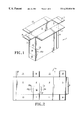
- FIG. 1 is a perspective view of the carton of the present invention with its top flaps open.
- FIG. 2 is an elevational view of the blank from which the outside carton of FIG. 1 is made illustrating the inside surface of the carton blank.
- FIG. 3 is an elevational view of the blank from which the insert of the present invention is made, illustrating the inside surface of the insert blank.
- FIG. 4 is an elevational view of the insert of FIG. 3 with the rail elements folded and glued in position.
- FIG. 5 is a front end elevational view of the carton assembly of the present invention.
- FIG. 6 is a cross-sectional view of the carton assembly, taken along section line 6 — 6 of FIG. 5 .
- FIG. 7 is a fragmentary cross-sectional view of a single ply corrugated board from which some portions of the carton assembly are made.
- FIG. 8 is a fragmentary cross-sectional view of a double ply corrugated board from which some parts of the carton assembly of the present invention are made.
- FIG. 9 is an elevational view of the blank of FIG. 2 with the guide elements affixed directly thereto.
- FIG. 2 illustrates the inside surface of the carton blank 1 a .
- the carton blank 1 a comprises a front wall 2 , a pair of side walls 3 and 4 , and a rear wall 5 .
- the vertical edge of rear wall 5 opposite its vertical edge adjacent side wall 3 , carries an assembly tab 6 .
- the front wall 2 , side walls 3 and 4 , and rear wall 5 are folded into a rectangular shape.
- the assembly tab 6 is glued to the outside surface of side wall 4 at the free end thereof, to maintain the side and end walls in the rectangular configuration shown.
- Front wall 2 carries a bottom closure flap 7 and a top closure flap 8 .
- the rear wall 5 carries a bottom closure flap 9 and a top closure flap 10 .
- Side wall 3 carries a bottom closure flap 11 and a top closure flap 12
- side wall 4 carries a bottom closure flap 13 and a top closure flap 14 .
- FIGS. 1, 5 and 6 illustrate the bottom closure flaps in closed condition.
- end flaps 7 and 8 are first folded inwardly, followed by flap 13 and then flap 11 .
- the top flaps 8 , 10 , 12 and 14 are shown open in FIG. 1 and closed in FIGS. 5 and 6.
- end flaps 8 and 10 are first folded inwardly, followed by flap 12 and then flap 13 .
- the carton 1 is completed by providing a tear-out dispensing opening which is initially closed for shipping and storage.
- the opening is indicated at 15 in FIGS. 1, 2 and 5 with portions 15 a and 15 b which extend into side walls 3 and 4 , respectively.
- the opening 15 and its extensions 15 a and 15 b are illustrated in broken lines since opening 15 initially defined by a continuous line of perforations in front wall 2 and side walls 3 and 4 .
- At the outermost parts of the extensions 15 a and 15 b there are perforated portions 15 c and 15 d which may be punched inwardly to provide finger holes. In this manner, the tear-out part 16 of the carton may be manually engaged and removed to form dispensing opening 15 .
- dispensing opening 15 is spaced upwardly from the bottom edge of front panel 2 to form an abutment wall, as will be apparent hereinafter.
- the opening extensions 15 a and 15 b enable the forwardmost and bottom most spool of wire to be manually lifted through the dispensing opening 15 .
- the carton 1 can be made of any appropriate material. Excellent results have been achieved using a single ply corrugated cardboard of the type shown at 17 in FIG. 7, comprising an outer sheet 17 a , a corrugated sheet 17 b , and an inner sheet 7 c .
- FIG. 3 is an elevational view showing the inside surface of the blank or insert generally indicated at 18 .
- the insert 18 may be made of any appropriate material. Excellent results have been achieved using a two-ply corrugated board such as is shown in FIG. 8 at 19 .
- the two-ply corrugated board 19 comprises an outer sheet 20 , a first corrugated sheet 21 , an intermediate sheet 22 , a second corrugated sheet 23 , and an inner sheet 24 .
- FIG. 3 the inside surface of insert 18 is shown.
- the insert 18 comprises a rear wall 25 flanked by side walls 26 and 27 . Rear wall 25 is sized to abut the inside surface of rear wall 5 of the carton 1 .
- Side walls 26 and 27 are sized to fit against and abut carton side walls 3 and 4 , respectively. It will be noted that side walls 26 and 27 have their lower forward corners notched as at 28 and 29 so that the insert does not interfere with the dispensing opening extensions 15 a and 15 b .
- upper guide elements 30 and 31 which constitute an integral, one-piece part of blank 18 . It will be noted that the upper guide elements 30 and 31 do not extend all the way to the forward edges of side walls 26 and 27 , as will be explained hereinafter.
- Side walls 26 and 27 also have, along their bottom edges, bottom guide elements 32 and 33 , respectively which extend from points just inside the rear edges of side walls 26 and 27 to the notches 28 and 29 , respectively.
- the side walls 26 and 27 of insert 18 have triangular intermediate guide elements 34 and 35 , respectively.
- the rail elements 34 and 35 constitute an integral, one-piece part of blank 18 .
- the side wall is cut all the way through along line 34 a .
- side wall 26 is cut through outer sheet 20 , corrugated sheet 21 , intermediate sheet 22 and corrugated sheet 23 , but not through inner sheet 24 .
- guide element 35 of side wall 27 The side wall is cut through along line 35 a , and is cut along 35 b with the exception of inner sheet 24 .
- Glue is applied to the inside surfaces of guide elements 34 and 35 and they are bent upwardly, as viewed in FIG. 3, to the positions shown in FIG. 4 .
- the inner sheet 24 of the blank serves as a hinge during the guide element folding process and thereby properly locates each of the guide elements on the inside surface of insert 18 . It would be within the scope of the invention to make the upper and lower guide elements 30 - 33 , or all of the guide elements 30 - 35 , as separate pieces to be adhered to the inside surface of insert 18 .
- FIG. 6 is a cross-sectional view of the carton 1 and insert 18 , taken along section line 6 — 6 of FIG. 5 .
- the completed insert 18 as shown in FIG. 4, is bent along the lines of junction between its rear wall 25 and its side walls 26 and 27 .
- the insert is lowered into the carton 1 with the exterior side of the insert rear wall 25 abutting the inside surface of the carton rear wall 5 and the exterior surfaces of insert side walls 26 and 27 abutting the inside surfaces of carton side walls 3 and 4 , respectively.
- the carton 1 holds 6 spools 36 a - 36 f .
- the uppermost guide element 30 (and the corresponding uppermost guide element 31 , not shown in FIG.
- edges 30 b and 31 b (see FIG. 4) which serve primarily to maintain the upper row of spools 36 d - 36 f in proper position when carton 1 is supported on any one of its exterior surfaces other than its bottom.
- the intermediate guide element 34 and the bottom guide element 32 and their counterparts 35 and 33 on insert side 27 serve the same purpose as guide elements 30 and 31 when the carton is in any position other than its upright position as shown in FIG. 6 .
- the intermediate guide elements 34 and 35 and the bottom guide elements 32 and 33 provide upper, rail-like edges 34 c , 35 c , 32 b and 33 b (see also FIG. 4) which support the spools and along which they may roll during a dispensing operation.
- Guide elements 34 , 35 , 32 and 33 arrange spools 36 a - 36 f in a “zig-zag” path of travel, as is apparent from FIG. 6 .
- the carton 1 of the present invention and its insert 18 having been described in detail, its mode of operation may now be set forth.
- the carton 1 is erected as shown in FIG. 1, with its top flaps 8 , 10 , 12 and 14 in open position.
- the insert 18 having been bent along the junctures of its rear wall 25 and side walls 26 and 27 is inserted in the open top of carton 1 .
- side wall 3 extends all the way to the inside surface of the carton front wall 2 .
- side wall 27 does not extend all the way to the front wall 2 of the carton, but is spaced therefrom by a distance slightly greater than the diameter of each spool 36 a - 36 f .
- guide element 31 see FIG. 4 .
- the opening 15 is of such a height that any one of spools 36 a - 36 f can readily be extracted therefrom. It will further be noted in FIG. 5 that the opening 15 is spaced upwardly from the bottom of carton 1 thereby providing a retaining wall indicated at 37 . The purpose of retaining wall 37 is to maintain the forwardmost spool of the carton within the carton until manually extracted therefrom.
- the rail-ike upper edges 34 c and 35 c of the intermediate guide elements 34 and 35 and the upper rail-like edges 32 b and 33 b of the lower guide elements 32 and 33 are of sufficient width to support the circular ends of the spools 36 a - 36 f , the guide elements being made of double ply board.
- the zig-zag path of travel of the rolls 36 a - 36 f , induced by the intermediate guide elements 34 and 35 and the lower guide elements 32 and 33 assure that the spools will not drop, minimizing the possibility of spool breakage or injury.
- the carton of the present invention may be used to dispense any product elements having circular ends of the same diameter.
- guide elements 30 , 31 , 34 , 35 , 32 and 33 directly to the inside surface of the carton blank, as shown in FIG. 9 .
- FIG. 9 the carton blank 1 a of FIG. 2 is shown.
- the carton blank 38 a is provided with the upper guide elements 30 and 31 , lower guide elements 32 and 33 and intermediate guide elements 34 and 35 of FIG. 4 . All of the guide elements 30 - 35 are adhered directly to the carton blank 1 a , rather than to an insert. It will be understood that the carton blank 1 a may be made of single or multiple ply board.
- the guide elements 39 - 44 It would also be well within the skill of the worker in the art to size the carton assembly to fit the product to be housed therein.
- the product elements are arranged in two sloping rows which move in opposite directions. It will be understood that the carton could be provided with any number of oppositely sloping rows, located one above the other.
Landscapes
- Engineering & Computer Science (AREA)
- Mechanical Engineering (AREA)
- Cartons (AREA)
Abstract
Description
Claims (8)
Priority Applications (1)
| Application Number | Priority Date | Filing Date | Title |
|---|---|---|---|
| US08/907,846 US6253930B1 (en) | 1997-08-08 | 1997-08-08 | Dispensing carton assembly |
Applications Claiming Priority (1)
| Application Number | Priority Date | Filing Date | Title |
|---|---|---|---|
| US08/907,846 US6253930B1 (en) | 1997-08-08 | 1997-08-08 | Dispensing carton assembly |
Publications (1)
| Publication Number | Publication Date |
|---|---|
| US6253930B1 true US6253930B1 (en) | 2001-07-03 |
Family
ID=25424739
Family Applications (1)
| Application Number | Title | Priority Date | Filing Date |
|---|---|---|---|
| US08/907,846 Expired - Fee Related US6253930B1 (en) | 1997-08-08 | 1997-08-08 | Dispensing carton assembly |
Country Status (1)
| Country | Link |
|---|---|
| US (1) | US6253930B1 (en) |
Cited By (50)
| Publication number | Priority date | Publication date | Assignee | Title |
|---|---|---|---|---|
| US6604638B1 (en) * | 2002-03-11 | 2003-08-12 | Display Industries, Llc. | Merchandising display track device with bottle ramp |
| US20050178791A1 (en) * | 2003-12-02 | 2005-08-18 | The C.W. Zumbiel Company | Contoured carton with dispenser |
| US20050194430A1 (en) * | 2004-03-05 | 2005-09-08 | Jean Michel Auclair | Carton with removable corner portion |
| US20050274638A1 (en) * | 2004-06-09 | 2005-12-15 | Georgia-Pacific Corporation | Combination shipping container and dispenser |
| US20060016864A1 (en) * | 2003-02-22 | 2006-01-26 | Harrelson Glen R | Paperboard carton with two new types of dispensers |
| US20060060547A1 (en) * | 2004-09-22 | 2006-03-23 | Chao-Tsung Chang | Storage and display carton |
| US20070114151A1 (en) * | 2003-10-31 | 2007-05-24 | Auclair Jean M | Carton with dispensing feature for cans |
| DE102006013178A1 (en) * | 2006-03-22 | 2007-09-27 | Illinois Tool Works Inc., Glenview | Sealing cord spool dispenser has filling opening at upper shaft end for filling storage shaft with spools and removal opening at lower shaft end or perforation line for breaking out removal opening for successive manual removal of spools |
| US20070295680A1 (en) * | 2005-02-02 | 2007-12-27 | Jason Budge | Apparatus system and method for storing cylindrical containers |
| US20090212066A1 (en) * | 2008-02-25 | 2009-08-27 | Jamie Bauer | Product dispenser assembly and cartridge for holding product |
| US20090277853A1 (en) * | 2008-02-25 | 2009-11-12 | Jamie Bauer | Product Dispenser Assembly |
| US20090314663A1 (en) * | 2005-10-07 | 2009-12-24 | Holley Jr John M | Carton with insert and dispenser |
| US20100044421A1 (en) * | 2008-08-21 | 2010-02-25 | Learn Angela E | Package for containers |
| US7922437B1 (en) * | 2009-11-23 | 2011-04-12 | Meadwestvaco Corporation | Display system, dispensing device and package for use therein |
| US20110121022A1 (en) * | 2009-11-23 | 2011-05-26 | Sholl Andrew B | Product Dispenser With Low Product Indicator |
| US20110121011A1 (en) * | 2009-11-23 | 2011-05-26 | John Gelardi | Product Dispensing System With Anti-Theft Engagement |
| US8118212B2 (en) | 2002-11-07 | 2012-02-21 | The C.W. Zumbiel Co. | Carton with dispenser |
| US20120074211A1 (en) * | 2010-09-25 | 2012-03-29 | John Gelardi | Paperboard Container with Friction-Reducing Coating |
| WO2012118595A1 (en) * | 2011-03-03 | 2012-09-07 | Meadwestvaco Corporation | Dispensing system |
| US8302809B1 (en) | 2011-05-11 | 2012-11-06 | Meadwestvaco Corporation | Product dispensing system with increased product-to-dispenser contact |
| US8308023B2 (en) | 2011-02-23 | 2012-11-13 | Meadwestvaco Corporation | Product dispensing system with directional flexing container |
| US8322543B2 (en) | 2010-07-23 | 2012-12-04 | Meadwestvaco Corporation | Product dispensing apparatus and system |
| US20120325762A1 (en) * | 2009-12-11 | 2012-12-27 | Burke Raymond J | Display tray |
| US8408392B2 (en) | 2003-02-12 | 2013-04-02 | Graphic Packaging International, Inc. | Dispensing system for double stack carton |
| US8550261B2 (en) | 2011-09-09 | 2013-10-08 | Meadwestvaco Corporation | Product dispensing system with flexing container |
| US8628003B2 (en) | 2010-09-25 | 2014-01-14 | Meadwestvaco Corporation | Product dispensing container, system and method with priming area |
| US8657126B1 (en) | 2012-08-27 | 2014-02-25 | Meadwestvaco Corporation | Product dispensing system with dispenser door |
| US8668114B2 (en) | 2011-05-02 | 2014-03-11 | Meadwestvaco Corporation | Dispensing system and package for use therewith |
| US8833601B2 (en) | 2012-02-24 | 2014-09-16 | Meadwestvaco Corporation | Product dispensing system with staggered perforations |
| US8851302B2 (en) | 2012-04-16 | 2014-10-07 | Meadwestvaco Corporation | Product dispensing system with container-product interaction |
| US20140319205A1 (en) * | 2013-04-30 | 2014-10-30 | Menasha Corporation | Gravity Feed Eye Shield Lens Tower |
| US8955695B2 (en) | 2013-03-14 | 2015-02-17 | Giraffx Design, LLC | Serpentine dispenser with cartridges |
| US8985346B2 (en) | 2011-09-08 | 2015-03-24 | Meadwestvaco Corporation | Multi-deck product dispensing system with rear guide |
| US9090390B2 (en) | 2010-09-27 | 2015-07-28 | Meadwestvaco Corporation | Product dispensing system |
| US9096345B2 (en) | 2013-08-22 | 2015-08-04 | Meadwestvaco Corporation | Product dispensing system with reinforced weakening features |
| US9174785B2 (en) | 2011-02-23 | 2015-11-03 | Westrock Mwv, Llc | Product dispensing system with panel guide |
| US9320365B2 (en) | 2012-08-31 | 2016-04-26 | Westrock Mwv, Llc | Product dispensing system with sound reducing features |
| US9359106B2 (en) | 2011-07-18 | 2016-06-07 | Westrock Mwv, Llc | Product dispensing system with multiple dispensing decks |
| US9361747B2 (en) | 2013-08-29 | 2016-06-07 | Giraffx Design, LLC | Dispenser with wedge for rolling products |
| US20160311578A1 (en) * | 2013-12-13 | 2016-10-27 | Westrock Packaging Systems, Llc | Systems and methods for dispensing articles |
| US9586749B2 (en) | 2013-04-30 | 2017-03-07 | Tidi Products, Llc | Eye shield lens dispenser tray |
| US10179671B2 (en) | 2013-03-15 | 2019-01-15 | Tidi Products, Llc | Dispenser-packaging for protective eyewear |
| US10272401B2 (en) * | 2017-04-20 | 2019-04-30 | Mo Siu Mei Lee | Non-electric portable blood tube mixer |
| US10981693B2 (en) | 2003-10-15 | 2021-04-20 | Graphic Packaging International, Llc | Display/vending carton |
| USD947022S1 (en) | 2019-05-17 | 2022-03-29 | Altria Client Services Llc | Carton/dispenser package |
| US11325742B2 (en) * | 2019-05-17 | 2022-05-10 | Altria Client Services Llc | Package with tear-off section and foot panel supporting platform panel |
| US11427378B2 (en) | 2013-03-15 | 2022-08-30 | Tidi Products, Llc | Eye shield dispenser |
| US20230312160A1 (en) * | 2019-05-17 | 2023-10-05 | Altria Client Services Llc | Method of forming blank with platform panel, first foot panel and second foot panel |
| USD1036989S1 (en) | 2019-05-17 | 2024-07-30 | Altria Client Services Llc | Dispensing carton |
| JP2024157153A (en) * | 2023-04-25 | 2024-11-07 | レック株式会社 | Display box |
Citations (28)
| Publication number | Priority date | Publication date | Assignee | Title |
|---|---|---|---|---|
| US1341893A (en) * | 1919-06-23 | 1920-06-01 | Gerald Ray H Fitz | Dispensing and displaying carton |
| US2299027A (en) * | 1940-03-20 | 1942-10-13 | Edward J Novak | Display carton |
| US2708085A (en) * | 1952-11-17 | 1955-05-10 | James F Bonaccorsi | Cradle type carton |
| US2795354A (en) * | 1953-06-29 | 1957-06-11 | Freundlich William | Cigarette dispenser |
| US2852327A (en) * | 1954-10-20 | 1958-09-16 | Brunhoff Mfg Co | Can dispenser for refrigerator |
| US2901118A (en) * | 1958-06-11 | 1959-08-25 | Scott L Beesley | Storing and dispensing apparatus |
| US2996344A (en) * | 1958-02-05 | 1961-08-15 | Owens Illinois Glass Co | Dispensing carton |
| US3055293A (en) * | 1960-08-05 | 1962-09-25 | Michael J Lariccia | Storage and dispensing rack for cans and the like |
| US3298763A (en) * | 1965-02-08 | 1967-01-17 | Domenico Joseph Di | Device for dispensing cylindrical articles |
| US3300115A (en) | 1965-04-05 | 1967-01-24 | Boise Cascade Corp | Compartmented dispensing carton formed from a single blank |
| US3332594A (en) * | 1965-10-22 | 1967-07-25 | Olin Mathieson | Container for shotgun shells |
| US3351209A (en) * | 1965-08-10 | 1967-11-07 | Diamond Crystal Salt Co | Packet dispenser |
| US3356279A (en) | 1966-02-23 | 1967-12-05 | Reynolds Metals Co | Shipping and dispensing container means and blanks therefor |
| US3416719A (en) * | 1965-10-21 | 1968-12-17 | Reynolds Metals Co | Container means and blanks for making same |
| US3450308A (en) | 1967-10-06 | 1969-06-17 | William C Schoenefeld | Article dispenser having an inclined bottom ramp and a front wall article outlet opening |
| US3533536A (en) * | 1968-05-13 | 1970-10-13 | Vendo Co | Serpentine column dispensing machine having associated pre-cool rack |
| US3743137A (en) * | 1971-07-13 | 1973-07-03 | C Bennett | Rollable article dispenser |
| US3894681A (en) * | 1973-03-26 | 1975-07-15 | Federal Paper Board Co Inc | Carton |
| US4214660A (en) * | 1979-03-19 | 1980-07-29 | Hunt Letcher B Jr | Carton for beverage cans |
| US4283000A (en) * | 1980-02-04 | 1981-08-11 | Patrick H. Joyce | Sample holder/dispenser |
| US4287992A (en) * | 1978-07-11 | 1981-09-08 | Shimoda Kogyo, Ltd. | Rack structure |
| US4435026A (en) * | 1982-06-07 | 1984-03-06 | Johnson Michael R | Modular stacking trays |
| US4530548A (en) | 1983-06-15 | 1985-07-23 | The Mead Corporation | Article dispenser |
| US4911309A (en) * | 1988-08-25 | 1990-03-27 | Alexander Stefan | Storage rack for cylindrical cans |
| US5009329A (en) * | 1989-10-18 | 1991-04-23 | Farrentine Anselmo N | Dispensing apparatus |
| US5163558A (en) * | 1990-03-23 | 1992-11-17 | Faricerca Spa | Package having sanitary products therein |
| US5462198A (en) * | 1994-03-23 | 1995-10-31 | Miles Inc. | Modular bottle dispenser |
| US5597114A (en) | 1994-02-16 | 1997-01-28 | Kramedjian; Armand J. | Interlocking modular product delivery system |
-
1997
- 1997-08-08 US US08/907,846 patent/US6253930B1/en not_active Expired - Fee Related
Patent Citations (28)
| Publication number | Priority date | Publication date | Assignee | Title |
|---|---|---|---|---|
| US1341893A (en) * | 1919-06-23 | 1920-06-01 | Gerald Ray H Fitz | Dispensing and displaying carton |
| US2299027A (en) * | 1940-03-20 | 1942-10-13 | Edward J Novak | Display carton |
| US2708085A (en) * | 1952-11-17 | 1955-05-10 | James F Bonaccorsi | Cradle type carton |
| US2795354A (en) * | 1953-06-29 | 1957-06-11 | Freundlich William | Cigarette dispenser |
| US2852327A (en) * | 1954-10-20 | 1958-09-16 | Brunhoff Mfg Co | Can dispenser for refrigerator |
| US2996344A (en) * | 1958-02-05 | 1961-08-15 | Owens Illinois Glass Co | Dispensing carton |
| US2901118A (en) * | 1958-06-11 | 1959-08-25 | Scott L Beesley | Storing and dispensing apparatus |
| US3055293A (en) * | 1960-08-05 | 1962-09-25 | Michael J Lariccia | Storage and dispensing rack for cans and the like |
| US3298763A (en) * | 1965-02-08 | 1967-01-17 | Domenico Joseph Di | Device for dispensing cylindrical articles |
| US3300115A (en) | 1965-04-05 | 1967-01-24 | Boise Cascade Corp | Compartmented dispensing carton formed from a single blank |
| US3351209A (en) * | 1965-08-10 | 1967-11-07 | Diamond Crystal Salt Co | Packet dispenser |
| US3416719A (en) * | 1965-10-21 | 1968-12-17 | Reynolds Metals Co | Container means and blanks for making same |
| US3332594A (en) * | 1965-10-22 | 1967-07-25 | Olin Mathieson | Container for shotgun shells |
| US3356279A (en) | 1966-02-23 | 1967-12-05 | Reynolds Metals Co | Shipping and dispensing container means and blanks therefor |
| US3450308A (en) | 1967-10-06 | 1969-06-17 | William C Schoenefeld | Article dispenser having an inclined bottom ramp and a front wall article outlet opening |
| US3533536A (en) * | 1968-05-13 | 1970-10-13 | Vendo Co | Serpentine column dispensing machine having associated pre-cool rack |
| US3743137A (en) * | 1971-07-13 | 1973-07-03 | C Bennett | Rollable article dispenser |
| US3894681A (en) * | 1973-03-26 | 1975-07-15 | Federal Paper Board Co Inc | Carton |
| US4287992A (en) * | 1978-07-11 | 1981-09-08 | Shimoda Kogyo, Ltd. | Rack structure |
| US4214660A (en) * | 1979-03-19 | 1980-07-29 | Hunt Letcher B Jr | Carton for beverage cans |
| US4283000A (en) * | 1980-02-04 | 1981-08-11 | Patrick H. Joyce | Sample holder/dispenser |
| US4435026A (en) * | 1982-06-07 | 1984-03-06 | Johnson Michael R | Modular stacking trays |
| US4530548A (en) | 1983-06-15 | 1985-07-23 | The Mead Corporation | Article dispenser |
| US4911309A (en) * | 1988-08-25 | 1990-03-27 | Alexander Stefan | Storage rack for cylindrical cans |
| US5009329A (en) * | 1989-10-18 | 1991-04-23 | Farrentine Anselmo N | Dispensing apparatus |
| US5163558A (en) * | 1990-03-23 | 1992-11-17 | Faricerca Spa | Package having sanitary products therein |
| US5597114A (en) | 1994-02-16 | 1997-01-28 | Kramedjian; Armand J. | Interlocking modular product delivery system |
| US5462198A (en) * | 1994-03-23 | 1995-10-31 | Miles Inc. | Modular bottle dispenser |
Cited By (79)
| Publication number | Priority date | Publication date | Assignee | Title |
|---|---|---|---|---|
| US6604638B1 (en) * | 2002-03-11 | 2003-08-12 | Display Industries, Llc. | Merchandising display track device with bottle ramp |
| US8646654B2 (en) | 2002-11-07 | 2014-02-11 | The C.W. Zumbiel Company | Carton with dispenser |
| US8118212B2 (en) | 2002-11-07 | 2012-02-21 | The C.W. Zumbiel Co. | Carton with dispenser |
| US8881901B2 (en) | 2003-02-12 | 2014-11-11 | Graphic Packaging International, Inc. | Dispensing system for double stack carton |
| US8408392B2 (en) | 2003-02-12 | 2013-04-02 | Graphic Packaging International, Inc. | Dispensing system for double stack carton |
| US9452874B2 (en) | 2003-02-12 | 2016-09-27 | Graphic Packaging International, Inc. | Dispensing system for double stack carton |
| US20100252619A1 (en) * | 2003-02-22 | 2010-10-07 | Harrelson Glen R | Paperboard Carton With Two New Types Of Dispensers |
| US8162206B2 (en) | 2003-02-22 | 2012-04-24 | Graphic Packaging International, Inc. | Paperboard carton with two new types of dispensers |
| US7762451B2 (en) * | 2003-02-22 | 2010-07-27 | Graphic Packaging International, Inc. | Paperboard carton with two new types of dispensers |
| US20060016864A1 (en) * | 2003-02-22 | 2006-01-26 | Harrelson Glen R | Paperboard carton with two new types of dispensers |
| US20080099545A1 (en) * | 2003-02-22 | 2008-05-01 | Harrelson Glen R | Paperboard Carton With A New Type Of Dispenser |
| US7552857B2 (en) | 2003-02-22 | 2009-06-30 | Graphic Packaging International, Inc. | Paperboard carton with a new type of dispenser |
| US10981693B2 (en) | 2003-10-15 | 2021-04-20 | Graphic Packaging International, Llc | Display/vending carton |
| US20070114151A1 (en) * | 2003-10-31 | 2007-05-24 | Auclair Jean M | Carton with dispensing feature for cans |
| US7000803B2 (en) | 2003-12-02 | 2006-02-21 | The C.W. Zumbiel Company | Contoured carton with dispenser |
| US20050178791A1 (en) * | 2003-12-02 | 2005-08-18 | The C.W. Zumbiel Company | Contoured carton with dispenser |
| US7296731B2 (en) * | 2004-03-05 | 2007-11-20 | Meadwestvaco Packaging Systems, Llc | Carton with removable corner portion |
| US20050194430A1 (en) * | 2004-03-05 | 2005-09-08 | Jean Michel Auclair | Carton with removable corner portion |
| US7648048B2 (en) | 2004-06-09 | 2010-01-19 | Georgia-Pacific Corrugated Llc | Combination shipping container and dispenser |
| US20050274638A1 (en) * | 2004-06-09 | 2005-12-15 | Georgia-Pacific Corporation | Combination shipping container and dispenser |
| US20060060547A1 (en) * | 2004-09-22 | 2006-03-23 | Chao-Tsung Chang | Storage and display carton |
| US20070295680A1 (en) * | 2005-02-02 | 2007-12-27 | Jason Budge | Apparatus system and method for storing cylindrical containers |
| US7841479B2 (en) * | 2005-02-02 | 2010-11-30 | Cache Futures Inc. | Apparatus system and method for storing cylindrical containers |
| US7870957B2 (en) * | 2005-10-07 | 2011-01-18 | Meadwestvaco Packaging Systems, Llc | Carton with insert and dispenser |
| US20090314663A1 (en) * | 2005-10-07 | 2009-12-24 | Holley Jr John M | Carton with insert and dispenser |
| DE102006013178A1 (en) * | 2006-03-22 | 2007-09-27 | Illinois Tool Works Inc., Glenview | Sealing cord spool dispenser has filling opening at upper shaft end for filling storage shaft with spools and removal opening at lower shaft end or perforation line for breaking out removal opening for successive manual removal of spools |
| US7992747B2 (en) | 2008-02-25 | 2011-08-09 | Jamie Bauer | Product dispenser assembly and cartridge for holding product |
| US20090277853A1 (en) * | 2008-02-25 | 2009-11-12 | Jamie Bauer | Product Dispenser Assembly |
| US20090212066A1 (en) * | 2008-02-25 | 2009-08-27 | Jamie Bauer | Product dispenser assembly and cartridge for holding product |
| US20100044421A1 (en) * | 2008-08-21 | 2010-02-25 | Learn Angela E | Package for containers |
| US20110121022A1 (en) * | 2009-11-23 | 2011-05-26 | Sholl Andrew B | Product Dispenser With Low Product Indicator |
| US7922437B1 (en) * | 2009-11-23 | 2011-04-12 | Meadwestvaco Corporation | Display system, dispensing device and package for use therein |
| US20110121010A1 (en) * | 2009-11-23 | 2011-05-26 | Loftin Caleb S | Display System, Dispensing Device and Package For Use Therein |
| US8448815B2 (en) | 2009-11-23 | 2013-05-28 | Meadwestvaco Corporation | Product dispenser with low product indicator |
| US9790013B2 (en) | 2009-11-23 | 2017-10-17 | Westrock Mwv, Llc | Dispensing system and package for use therewith |
| US20110121011A1 (en) * | 2009-11-23 | 2011-05-26 | John Gelardi | Product Dispensing System With Anti-Theft Engagement |
| US9591933B2 (en) * | 2009-12-11 | 2017-03-14 | Wm. Wrigley Jr. Company | Display tray |
| US20120325762A1 (en) * | 2009-12-11 | 2012-12-27 | Burke Raymond J | Display tray |
| US8322543B2 (en) | 2010-07-23 | 2012-12-04 | Meadwestvaco Corporation | Product dispensing apparatus and system |
| US20120074211A1 (en) * | 2010-09-25 | 2012-03-29 | John Gelardi | Paperboard Container with Friction-Reducing Coating |
| US8628003B2 (en) | 2010-09-25 | 2014-01-14 | Meadwestvaco Corporation | Product dispensing container, system and method with priming area |
| US9102456B2 (en) | 2010-09-25 | 2015-08-11 | Meadwestvaco Corporation | Product dispensing container, system and method with priming area |
| US9096361B2 (en) | 2010-09-25 | 2015-08-04 | Meadwestvaco Corporation | Product dispensing container, system and method with priming area |
| US9090390B2 (en) | 2010-09-27 | 2015-07-28 | Meadwestvaco Corporation | Product dispensing system |
| US9174785B2 (en) | 2011-02-23 | 2015-11-03 | Westrock Mwv, Llc | Product dispensing system with panel guide |
| US8308023B2 (en) | 2011-02-23 | 2012-11-13 | Meadwestvaco Corporation | Product dispensing system with directional flexing container |
| WO2012118595A1 (en) * | 2011-03-03 | 2012-09-07 | Meadwestvaco Corporation | Dispensing system |
| US8668114B2 (en) | 2011-05-02 | 2014-03-11 | Meadwestvaco Corporation | Dispensing system and package for use therewith |
| CN103502103A (en) * | 2011-05-11 | 2014-01-08 | 米德韦斯瓦科公司 | Product dispensing system with increased product-to-dispenser contact |
| US8302809B1 (en) | 2011-05-11 | 2012-11-06 | Meadwestvaco Corporation | Product dispensing system with increased product-to-dispenser contact |
| US9359106B2 (en) | 2011-07-18 | 2016-06-07 | Westrock Mwv, Llc | Product dispensing system with multiple dispensing decks |
| US8985346B2 (en) | 2011-09-08 | 2015-03-24 | Meadwestvaco Corporation | Multi-deck product dispensing system with rear guide |
| US8550261B2 (en) | 2011-09-09 | 2013-10-08 | Meadwestvaco Corporation | Product dispensing system with flexing container |
| US8833601B2 (en) | 2012-02-24 | 2014-09-16 | Meadwestvaco Corporation | Product dispensing system with staggered perforations |
| US8851302B2 (en) | 2012-04-16 | 2014-10-07 | Meadwestvaco Corporation | Product dispensing system with container-product interaction |
| US8657126B1 (en) | 2012-08-27 | 2014-02-25 | Meadwestvaco Corporation | Product dispensing system with dispenser door |
| US9320365B2 (en) | 2012-08-31 | 2016-04-26 | Westrock Mwv, Llc | Product dispensing system with sound reducing features |
| US8955695B2 (en) | 2013-03-14 | 2015-02-17 | Giraffx Design, LLC | Serpentine dispenser with cartridges |
| US10669062B2 (en) | 2013-03-15 | 2020-06-02 | Tidi Products, Llc | Eye shield dispenser |
| US11427378B2 (en) | 2013-03-15 | 2022-08-30 | Tidi Products, Llc | Eye shield dispenser |
| US10179671B2 (en) | 2013-03-15 | 2019-01-15 | Tidi Products, Llc | Dispenser-packaging for protective eyewear |
| US20140319205A1 (en) * | 2013-04-30 | 2014-10-30 | Menasha Corporation | Gravity Feed Eye Shield Lens Tower |
| US9586749B2 (en) | 2013-04-30 | 2017-03-07 | Tidi Products, Llc | Eye shield lens dispenser tray |
| US10065762B2 (en) * | 2013-04-30 | 2018-09-04 | Tidi Products, Llc | Dispenser having a tower portion and an insert portion |
| US9096345B2 (en) | 2013-08-22 | 2015-08-04 | Meadwestvaco Corporation | Product dispensing system with reinforced weakening features |
| US9361747B2 (en) | 2013-08-29 | 2016-06-07 | Giraffx Design, LLC | Dispenser with wedge for rolling products |
| US10861277B2 (en) | 2013-08-29 | 2020-12-08 | Rtc Industries, Inc. | Product dispenser with an s-shaped down chute |
| US9659426B2 (en) | 2013-08-29 | 2017-05-23 | Giraffx Design, LLC | Dispenser for rolling product and dispenser cartridges |
| US20160311578A1 (en) * | 2013-12-13 | 2016-10-27 | Westrock Packaging Systems, Llc | Systems and methods for dispensing articles |
| US10272401B2 (en) * | 2017-04-20 | 2019-04-30 | Mo Siu Mei Lee | Non-electric portable blood tube mixer |
| US11713156B2 (en) | 2019-05-17 | 2023-08-01 | Altria Client Services Llc | Method of using blank with tear-off section and supportive platform |
| US11325742B2 (en) * | 2019-05-17 | 2022-05-10 | Altria Client Services Llc | Package with tear-off section and foot panel supporting platform panel |
| USD947022S1 (en) | 2019-05-17 | 2022-03-29 | Altria Client Services Llc | Carton/dispenser package |
| US20230312160A1 (en) * | 2019-05-17 | 2023-10-05 | Altria Client Services Llc | Method of forming blank with platform panel, first foot panel and second foot panel |
| USD1036989S1 (en) | 2019-05-17 | 2024-07-30 | Altria Client Services Llc | Dispensing carton |
| US12145778B2 (en) * | 2019-05-17 | 2024-11-19 | Altria Client Services Llc | Method of forming blank with platform panel, first foot panel and second foot panel |
| US12151857B2 (en) | 2019-05-17 | 2024-11-26 | Altria Client Services Llc | Method of forming blank with platform panel and foot panel |
| USD1115519S1 (en) | 2019-05-17 | 2026-03-03 | Altria Client Services Llc | Carton/dispenser package |
| JP2024157153A (en) * | 2023-04-25 | 2024-11-07 | レック株式会社 | Display box |
Similar Documents
| Publication | Publication Date | Title |
|---|---|---|
| US6253930B1 (en) | Dispensing carton assembly | |
| US4387831A (en) | Container for dispensing articles carried on a web | |
| US4000811A (en) | Shipping-display container | |
| US5878947A (en) | Multiple article beverage package | |
| US2935192A (en) | Dispensing package | |
| US5351880A (en) | Multiple tier food package | |
| US7357254B2 (en) | Dispenser with detachable retention feature | |
| US7000803B2 (en) | Contoured carton with dispenser | |
| US7111735B2 (en) | Base for post in post product packaging and display system | |
| US4911311A (en) | Display stand with vertically stacked trays | |
| US5520325A (en) | Channel H divider pack | |
| US20030150759A1 (en) | Carrying carton and can dispenser | |
| US4993625A (en) | Tray | |
| US2361926A (en) | Package, container, and blank therefor | |
| US8789704B2 (en) | Shipping and display container | |
| JP2007527347A (en) | Carton with removable corner | |
| WO1996024527A1 (en) | Improved shipping/display container | |
| WO2006031873A2 (en) | Carton with article opening | |
| KR200492642Y1 (en) | Package box and goods dispenser | |
| US2518779A (en) | Display carton | |
| US20210100222A1 (en) | Shelf ready shipper with gravity feed opening | |
| US2797815A (en) | Sample display device | |
| US4128167A (en) | Shipping and display carton for plants and the like | |
| JPS636418B2 (en) | ||
| US4072232A (en) | Package for multiple containers |
Legal Events
| Date | Code | Title | Description |
|---|---|---|---|
| AS | Assignment |
Owner name: GENERAL CABLE CORPORATION, KENTUCKY Free format text: ASSIGNMENT OF ASSIGNORS INTEREST;ASSIGNORS:FREIDUS, SCOTT D.;CIESICK, JAMES M.;REEL/FRAME:009188/0874 Effective date: 19980422 |
|
| AS | Assignment |
Owner name: GENERAL CABLE TECHNOLOGIES CORPORATION, KENTUCKY Free format text: ASSIGNMENT OF ASSIGNORS INTEREST;ASSIGNOR:GENERAL CABLE CORPORATION;REEL/FRAME:009648/0043 Effective date: 19980831 |
|
| AS | Assignment |
Owner name: GENERAL CABLE TECHNOLOGIES CORPORATION, KENTUCKY Free format text: ASSIGNMENT OF ASSIGNORS INTEREST;ASSIGNOR:GENERAL CABLE CORPORATION;REEL/FRAME:011783/0068 Effective date: 19980831 |
|
| AS | Assignment |
Owner name: JPMORGAN CHASE BANK, NEW YORK Free format text: SECURITY AGREEMENT;ASSIGNOR:GENERAL CABLE TECHNOLOGIES CORPORATION;REEL/FRAME:013138/0311 Effective date: 20020425 |
|
| AS | Assignment |
Owner name: MERRILL LYNCH CAPITAL, A DIVISION OF MERRILL LYNCH Free format text: SECURITY INTEREST;ASSIGNOR:GENERAL CABLE TECHNOLOGIES CORPORATION;REEL/FRAME:014178/0121 Effective date: 20031124 |
|
| REMI | Maintenance fee reminder mailed | ||
| REMI | Maintenance fee reminder mailed | ||
| LAPS | Lapse for failure to pay maintenance fees | ||
| STCH | Information on status: patent discontinuation |
Free format text: PATENT EXPIRED DUE TO NONPAYMENT OF MAINTENANCE FEES UNDER 37 CFR 1.362 |
|
| FP | Lapsed due to failure to pay maintenance fee |
Effective date: 20050703 |
|
| AS | Assignment |
Owner name: GENERAL CABLE TECHNOLOGIES CORPORATION, KENTUCKY Free format text: RELEASE BY SECURED PARTY;ASSIGNOR:GE BUSINESS FINANCIAL SERVICES INC. (F/K/A MERRILL LYNCH BUSINESS FINANCIAL SERVICES INC.);REEL/FRAME:026706/0920 Effective date: 20110722 |
|
| AS | Assignment |
Owner name: GENERAL CABLE TECHNOLOGIES CORPORATION, KENTUCKY Free format text: RELEASE BY SECURED PARTY;ASSIGNOR:JPMORGAN CHASE BANK, N.A.;REEL/FRAME:045812/0669 Effective date: 20180514 Owner name: GENERAL CABLE INDUSTRIES, INC., KENTUCKY Free format text: RELEASE BY SECURED PARTY;ASSIGNOR:JPMORGAN CHASE BANK, N.A.;REEL/FRAME:045812/0669 Effective date: 20180514 |