US6247374B1 - Locking mechanism for automatically immobilizing a carriage of a scanner at a rest position - Google Patents
Locking mechanism for automatically immobilizing a carriage of a scanner at a rest position Download PDFInfo
- Publication number
- US6247374B1 US6247374B1 US09/311,006 US31100699A US6247374B1 US 6247374 B1 US6247374 B1 US 6247374B1 US 31100699 A US31100699 A US 31100699A US 6247374 B1 US6247374 B1 US 6247374B1
- Authority
- US
- United States
- Prior art keywords
- carriage
- locking mechanism
- mechanism according
- rib
- transmitting
- Prior art date
- Legal status (The legal status is an assumption and is not a legal conclusion. Google has not performed a legal analysis and makes no representation as to the accuracy of the status listed.)
- Expired - Fee Related
Links
Images


Classifications
-
- H—ELECTRICITY
- H04—ELECTRIC COMMUNICATION TECHNIQUE
- H04N—PICTORIAL COMMUNICATION, e.g. TELEVISION
- H04N1/00—Scanning, transmission or reproduction of documents or the like, e.g. facsimile transmission; Details thereof
- H04N1/04—Scanning arrangements, i.e. arrangements for the displacement of active reading or reproducing elements relative to the original or reproducing medium, or vice versa
- H04N1/10—Scanning arrangements, i.e. arrangements for the displacement of active reading or reproducing elements relative to the original or reproducing medium, or vice versa using flat picture-bearing surfaces
- H04N1/1013—Scanning arrangements, i.e. arrangements for the displacement of active reading or reproducing elements relative to the original or reproducing medium, or vice versa using flat picture-bearing surfaces with sub-scanning by translatory movement of at least a part of the main-scanning components
- H04N1/1026—Scanning arrangements, i.e. arrangements for the displacement of active reading or reproducing elements relative to the original or reproducing medium, or vice versa using flat picture-bearing surfaces with sub-scanning by translatory movement of at least a part of the main-scanning components using a belt or cable
-
- H—ELECTRICITY
- H04—ELECTRIC COMMUNICATION TECHNIQUE
- H04N—PICTORIAL COMMUNICATION, e.g. TELEVISION
- H04N1/00—Scanning, transmission or reproduction of documents or the like, e.g. facsimile transmission; Details thereof
- H04N1/04—Scanning arrangements, i.e. arrangements for the displacement of active reading or reproducing elements relative to the original or reproducing medium, or vice versa
- H04N1/10—Scanning arrangements, i.e. arrangements for the displacement of active reading or reproducing elements relative to the original or reproducing medium, or vice versa using flat picture-bearing surfaces
- H04N1/1013—Scanning arrangements, i.e. arrangements for the displacement of active reading or reproducing elements relative to the original or reproducing medium, or vice versa using flat picture-bearing surfaces with sub-scanning by translatory movement of at least a part of the main-scanning components
- H04N1/1017—Scanning arrangements, i.e. arrangements for the displacement of active reading or reproducing elements relative to the original or reproducing medium, or vice versa using flat picture-bearing surfaces with sub-scanning by translatory movement of at least a part of the main-scanning components the main-scanning components remaining positionally invariant with respect to one another in the sub-scanning direction
-
- H—ELECTRICITY
- H04—ELECTRIC COMMUNICATION TECHNIQUE
- H04N—PICTORIAL COMMUNICATION, e.g. TELEVISION
- H04N1/00—Scanning, transmission or reproduction of documents or the like, e.g. facsimile transmission; Details thereof
- H04N1/04—Scanning arrangements, i.e. arrangements for the displacement of active reading or reproducing elements relative to the original or reproducing medium, or vice versa
- H04N1/10—Scanning arrangements, i.e. arrangements for the displacement of active reading or reproducing elements relative to the original or reproducing medium, or vice versa using flat picture-bearing surfaces
- H04N1/1013—Scanning arrangements, i.e. arrangements for the displacement of active reading or reproducing elements relative to the original or reproducing medium, or vice versa using flat picture-bearing surfaces with sub-scanning by translatory movement of at least a part of the main-scanning components
-
- H—ELECTRICITY
- H04—ELECTRIC COMMUNICATION TECHNIQUE
- H04N—PICTORIAL COMMUNICATION, e.g. TELEVISION
- H04N1/00—Scanning, transmission or reproduction of documents or the like, e.g. facsimile transmission; Details thereof
- H04N1/04—Scanning arrangements, i.e. arrangements for the displacement of active reading or reproducing elements relative to the original or reproducing medium, or vice versa
- H04N1/19—Scanning arrangements, i.e. arrangements for the displacement of active reading or reproducing elements relative to the original or reproducing medium, or vice versa using multi-element arrays
- H04N1/191—Scanning arrangements, i.e. arrangements for the displacement of active reading or reproducing elements relative to the original or reproducing medium, or vice versa using multi-element arrays the array comprising a one-dimensional [1D] array
- H04N1/192—Simultaneously or substantially simultaneously scanning picture elements on one main scanning line
- H04N1/193—Simultaneously or substantially simultaneously scanning picture elements on one main scanning line using electrically scanned linear arrays, e.g. linear CCD arrays
-
- H—ELECTRICITY
- H04—ELECTRIC COMMUNICATION TECHNIQUE
- H04N—PICTORIAL COMMUNICATION, e.g. TELEVISION
- H04N2201/00—Indexing scheme relating to scanning, transmission or reproduction of documents or the like, and to details thereof
- H04N2201/04—Scanning arrangements
- H04N2201/0402—Arrangements not specific to a particular one of the scanning methods covered by groups H04N1/04 - H04N1/207
- H04N2201/0444—Arrangements not specific to a particular one of the scanning methods covered by groups H04N1/04 - H04N1/207 for securing moveable scanning components, e.g. for transportation
-
- Y—GENERAL TAGGING OF NEW TECHNOLOGICAL DEVELOPMENTS; GENERAL TAGGING OF CROSS-SECTIONAL TECHNOLOGIES SPANNING OVER SEVERAL SECTIONS OF THE IPC; TECHNICAL SUBJECTS COVERED BY FORMER USPC CROSS-REFERENCE ART COLLECTIONS [XRACs] AND DIGESTS
- Y10—TECHNICAL SUBJECTS COVERED BY FORMER USPC
- Y10T—TECHNICAL SUBJECTS COVERED BY FORMER US CLASSIFICATION
- Y10T74/00—Machine element or mechanism
- Y10T74/18—Mechanical movements
- Y10T74/18568—Reciprocating or oscillating to or from alternating rotary
- Y10T74/18832—Reciprocating or oscillating to or from alternating rotary including flexible drive connector [e.g., belt, chain, strand, etc.]
- Y10T74/18848—Reciprocating or oscillating to or from alternating rotary including flexible drive connector [e.g., belt, chain, strand, etc.] with pulley
Definitions
- the present invention relates to a locking mechanism for fixing a carriage automatically, and especially to a locking mechanism for fixing a scanning module of a flatbed scanner automatically when the scanning module is returned to a specific position.
- An object of the present invention is to provide a locking mechanism for fixing a carriage at a specific position automatically.
- the locking mechanism is adapted to be used in a scanner, preferably a flatbed scanner.
- the locking mechanism includes a fixing device for securing the carriage at the specific position, and a transmitting device for driving the carriage to be secured to the fixing device in a first instance and detaching the carriage from the fixing device in a second instance.
- the carriage is a scanning module, preferably a charged-coupled device (CCD) or a contact image sensor (CIS).
- the specific position is the threshold position of the carriage, and the carriage has a rib at one end thereof.
- the transmitting device of the present invention includes a driving device, a rotatable gear wheel driven by the driving device, a first belt mounted between the carriage and the gear wheel for driving the carriage to move in response to the rotation of the gear wheel, and a second belt mounted between the gear wheel and the fixing device for driving the fixing device to fix the carriage in response to the rotation of the gear wheel.
- the carriage is moved toward the fixing device when the driving device is actuated in a direction in the first instance and is moved away from the fixing device when the driving device is actuated in the other direction in the second instance.
- the driving device is a motor having a driving pinion
- the gear wheel has a plurality of teeth for engaging with the driving pinion of the motor.
- the gear wheel includes an upper portion for being surrounded by the second belt and a lower portion for being surrounded by the first belt. The upper portion of the gear wheel has a diameter smaller than that of the lower portion.
- the fixing device of the present invention includes a rotatable cam and a locking member.
- the cam is connected to the gear wheel through the second belt and driven by the second belt.
- the locking member is adjacent to the cam for preventing relative rotation of the cam and securing the carriage therein.
- the fixing device further includes a base for securing the locking member and the cam thereon.
- the locking member includes a detachable upper portion with a helical ramp at its lower end and a lower portion with a helical ramp at its upper end corresponding to that of the upper portion.
- the upper portion of the locking member has a first recess for engaging with a rib of the cam to prevent relative rotation of the cam, and has a second recess for engaging a rib of the carriage to secure the carriage therein.
- the upper portion of the locking member is rotated longitudinally upwardly at a specific angle, preferably 90 degrees, for engaging the second recess of the locking member with the rib of the carriage when the rib of the carriage is moved toward and biases against the upper portion of the locking member in the first instance.
- the upper portion of the locking member is rotated longitudinally downwardly for detaching the rib of the carriage from the second recess of the locking member when the driving device is actuated in the other direction in the second instance.
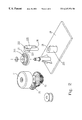
- FIG. 1 schematically shows the locking mechanism in a scanner according to the present invention
- FIG. 2 schematically shows the fixing device according to the present invention
- FIG. 3 is a top view showing the locking mechanism when the carriage is in motion.
- FIG. 4 is a top view showing the locking mechanism when the carriage is fixed at the specific position.
- the locking mechanism is used for fixing a carriage 14 at a specific position automatically and is adapted to be used in a scanner.
- This specific position is usually the threshold position or the original position of the carriage. In other words, this specific position is the place where the carriage is preset in the factory.
- the scanner is preferably a flatbed scanner and the carriage 14 preferably includes a scanning module, such as a charge-coupled device (CCD) and a contact image sensor (CIS).
- a scanning module such as a charge-coupled device (CCD) and a contact image sensor (CIS).
- the locking mechanism includes a fixing device and a transmitting device.
- the fixing device is used for securing the carriage 14 at the specific position
- the transmitting device is used for driving the carriage 14 to be secured to the fixing device in a first instance and allowing the carriage 14 to be detached from the fixing device in a second instance.
- the transmitting device includes a driving device 11 , a rotatable gear wheel 15 driven by the driving device 11 , a first belt 12 , and a second belt 13 .
- the first belt 12 is mounted between the carriage 14 and the gear wheel 15 for driving the carriage 14 to move in response to the rotation of the gear wheel 15 .
- the second belt 13 is mounted between the gear wheel 15 and the fixing device for driving the fixing device to fix the carriage 14 in response to the rotation of the gear wheel.
- the carriage 14 is moved toward the fixing device when the driving device 11 is actuated in a direction in the first instance and is moved away from the fixing device when the driving device is actuated in the other direction in the second instance.
- the driving device 11 of the present invention is preferably a motor 11 having a driving pinion 25 and there are a plurality of teeth on the gear wheel 15 for engaging with the driving pinion 25 of the motor 11 .
- the gear wheel 15 includes an upper portion 151 for being surrounded by the second belt 13 and a lower portion 152 for being surrounded by the first belt 12 .
- the diameter of the upper portion 151 is smaller than that of the lower portion 152 .
- FIG. 2 schematically shows the fixing device in detail according to the present invention.
- the fixing device includes a rotatable cam 21 and a locking member 22 .
- the cam 21 is connected to the gear wheel 15 through the second belt 13 and driven by the second belt 13 in response to the rotation of the gear wheel 15 .
- the locking member is adjacent to the cam 21 for preventing the relative rotation of the cam 21 and securing the carriage therein.
- the locking mechanism further includes a base 24 for securing the locking member 22 and the cam 21 thereon.
- the locking member includes a detachable upper portion 225 with a helical ramp 28 at its lower end, and a lower portion 226 with a helical ramp 29 at its upper end corresponding to the helical ramp 28 of the upper portion 225 .
- the first recess 222 is used for engaging with a rib 211 of the cam 21 to prevent the relative rotation of the cam 21 .
- the second recess 221 is used for engaging with a rib 23 of the carriage 14 to secure the carriage therein.
- the motor 11 is actuated in a direction, such as a clockwise direction, to move the carriage 14 toward the threshold position when the scanner is not in use.
- a direction such as a clockwise direction
- the upper portion 225 of the locking member 22 is rotated longitudinally upwardly at a specific angle for enabling the second recess 221 to engage with the rib 23 .
- the upper portion 225 is rotated by 90 degrees counterclockwise.
- the first recess 222 and the rib 211 of the cam 21 are positioned at the same height. Therefore, the rib 211 of the cam 21 will be engaged in the first recess 222 and the carriage 14 will be fixed automatically, as shown in FIG. 4 .
- the motor 11 is actuated in another direction, such as a counterclockwise direction, to move the carriage 14 away from the threshold position. Therefore, the rib 23 will not bias against the rim 223 of the second recess 221 and the upper portion 225 of the locking member 22 will be rotated longitudinally downwardly. At the very moment, the rib 23 of the carriage 14 is disengaged from the second recess 221 , and the rib 211 of the cam is disengaged from the first recess 222 . Further, because the locking member 22 is rotated downwardly, the cam 21 can be rotated freely.
- the locking mechanism of the present application can effectively prevent the damage caused by an improper operation.
- the carriage When the carriage is returned to the threshold position, no matter whether the scanner is turned on or off, the carriage can be fixed automatically.
- the automatically controlled locking mechanism is very convenient.
Landscapes
- Engineering & Computer Science (AREA)
- Multimedia (AREA)
- Signal Processing (AREA)
- Facsimile Scanning Arrangements (AREA)
- Optical Systems Of Projection Type Copiers (AREA)
Abstract
Description
Claims (32)
Priority Applications (2)
| Application Number | Priority Date | Filing Date | Title |
|---|---|---|---|
| US09/311,006 US6247374B1 (en) | 1999-05-13 | 1999-05-13 | Locking mechanism for automatically immobilizing a carriage of a scanner at a rest position |
| DE29908914U DE29908914U1 (en) | 1999-05-13 | 1999-05-20 | Locking mechanism |
Applications Claiming Priority (2)
| Application Number | Priority Date | Filing Date | Title |
|---|---|---|---|
| US09/311,006 US6247374B1 (en) | 1999-05-13 | 1999-05-13 | Locking mechanism for automatically immobilizing a carriage of a scanner at a rest position |
| DE29908914U DE29908914U1 (en) | 1999-05-13 | 1999-05-20 | Locking mechanism |
Publications (1)
| Publication Number | Publication Date |
|---|---|
| US6247374B1 true US6247374B1 (en) | 2001-06-19 |
Family
ID=26062512
Family Applications (1)
| Application Number | Title | Priority Date | Filing Date |
|---|---|---|---|
| US09/311,006 Expired - Fee Related US6247374B1 (en) | 1999-05-13 | 1999-05-13 | Locking mechanism for automatically immobilizing a carriage of a scanner at a rest position |
Country Status (2)
| Country | Link |
|---|---|
| US (1) | US6247374B1 (en) |
| DE (1) | DE29908914U1 (en) |
Cited By (10)
| Publication number | Priority date | Publication date | Assignee | Title |
|---|---|---|---|---|
| US20010010582A1 (en) * | 2000-01-13 | 2001-08-02 | Eiichi Hayashi | Carriage securing structure for image processor |
| US6402034B1 (en) * | 1999-08-24 | 2002-06-11 | Silitek Corporation | Locking device for scanner |
| US6529294B1 (en) * | 1999-09-08 | 2003-03-04 | Silitek Corporation | Securing device for scanner |
| US20030076545A1 (en) * | 2001-10-22 | 2003-04-24 | Chin-Te Liu | Locking device for a movable module of an apparatus |
| US20030123103A1 (en) * | 2001-12-27 | 2003-07-03 | Jen-Shou Tseng | Movable locking device for a scanner and locking method for the same |
| US20030231357A1 (en) * | 2002-05-31 | 2003-12-18 | Johnson Bruce L. | Optical scanning apparatus having a carriage locking device |
| US6700717B2 (en) * | 2002-07-16 | 2004-03-02 | Lite-On Technology Corporation | Scanning apparatus and locking device of scanning apparatus |
| US20050094217A1 (en) * | 2003-11-03 | 2005-05-05 | Erika Molchan | Optical assembly lock/unlock apparatus and method |
| US20050122722A1 (en) * | 2003-11-14 | 2005-06-09 | The Fire Products Company | Oscillating belt and pulley drive system for high performance light emitting diode warning light assembly |
| US20120192689A1 (en) * | 2011-02-02 | 2012-08-02 | New Tech Machinery | Guide assembly and sheet material slitter incorporating the same |
Citations (7)
| Publication number | Priority date | Publication date | Assignee | Title |
|---|---|---|---|---|
| US5444690A (en) * | 1993-11-12 | 1995-08-22 | International Business Machines Corporation | Leaf spring lock for a carriage in a media player that is actuated by the carriage and position of a cartridge |
| US5760926A (en) * | 1995-10-20 | 1998-06-02 | Apple Computer, Inc. | Apparatus for utilizing a single paper path for scanning, faxing, copying, and printing |
| US5767977A (en) * | 1996-12-19 | 1998-06-16 | Hewlett-Packard Co. | Method and apparatus for a carriage latch and power cord lock-out system for an optical scanner |
| US5791792A (en) * | 1991-03-12 | 1998-08-11 | Johnson; Reynold B. | Ideographic typewriter and method |
| US5907413A (en) * | 1997-04-10 | 1999-05-25 | Microtek International, Inc. | Contact image sensor flat bed scanner |
| US5973866A (en) * | 1998-09-22 | 1999-10-26 | Mustek System Inc. | Locking device for locking a scanning module in a scanner |
| US6043908A (en) * | 1997-01-06 | 2000-03-28 | Brother Kogyo Kabushiki Kaisha | Image reader for facsimile machine |
Family Cites Families (1)
| Publication number | Priority date | Publication date | Assignee | Title |
|---|---|---|---|---|
| JPH04371066A (en) | 1991-06-20 | 1992-12-24 | Canon Inc | Image reading device |
-
1999
- 1999-05-13 US US09/311,006 patent/US6247374B1/en not_active Expired - Fee Related
- 1999-05-20 DE DE29908914U patent/DE29908914U1/en not_active Expired - Lifetime
Patent Citations (7)
| Publication number | Priority date | Publication date | Assignee | Title |
|---|---|---|---|---|
| US5791792A (en) * | 1991-03-12 | 1998-08-11 | Johnson; Reynold B. | Ideographic typewriter and method |
| US5444690A (en) * | 1993-11-12 | 1995-08-22 | International Business Machines Corporation | Leaf spring lock for a carriage in a media player that is actuated by the carriage and position of a cartridge |
| US5760926A (en) * | 1995-10-20 | 1998-06-02 | Apple Computer, Inc. | Apparatus for utilizing a single paper path for scanning, faxing, copying, and printing |
| US5767977A (en) * | 1996-12-19 | 1998-06-16 | Hewlett-Packard Co. | Method and apparatus for a carriage latch and power cord lock-out system for an optical scanner |
| US6043908A (en) * | 1997-01-06 | 2000-03-28 | Brother Kogyo Kabushiki Kaisha | Image reader for facsimile machine |
| US5907413A (en) * | 1997-04-10 | 1999-05-25 | Microtek International, Inc. | Contact image sensor flat bed scanner |
| US5973866A (en) * | 1998-09-22 | 1999-10-26 | Mustek System Inc. | Locking device for locking a scanning module in a scanner |
Cited By (15)
| Publication number | Priority date | Publication date | Assignee | Title |
|---|---|---|---|---|
| US6402034B1 (en) * | 1999-08-24 | 2002-06-11 | Silitek Corporation | Locking device for scanner |
| US6529294B1 (en) * | 1999-09-08 | 2003-03-04 | Silitek Corporation | Securing device for scanner |
| US20010010582A1 (en) * | 2000-01-13 | 2001-08-02 | Eiichi Hayashi | Carriage securing structure for image processor |
| US6937368B2 (en) * | 2001-10-22 | 2005-08-30 | Lite-On Technology Corp. | Locking device for a movable module of an apparatus |
| US20030076545A1 (en) * | 2001-10-22 | 2003-04-24 | Chin-Te Liu | Locking device for a movable module of an apparatus |
| US20030123103A1 (en) * | 2001-12-27 | 2003-07-03 | Jen-Shou Tseng | Movable locking device for a scanner and locking method for the same |
| US7295353B2 (en) * | 2001-12-27 | 2007-11-13 | Transpacific Ip, Ltd. | Movable locking device for a scanner and locking method for the same |
| US20030231357A1 (en) * | 2002-05-31 | 2003-12-18 | Johnson Bruce L. | Optical scanning apparatus having a carriage locking device |
| US7068401B2 (en) | 2002-05-31 | 2006-06-27 | Hewlett-Packard Development Company, L.P. | Optical scanning apparatus having a carriage locking device |
| US6700717B2 (en) * | 2002-07-16 | 2004-03-02 | Lite-On Technology Corporation | Scanning apparatus and locking device of scanning apparatus |
| US20050094217A1 (en) * | 2003-11-03 | 2005-05-05 | Erika Molchan | Optical assembly lock/unlock apparatus and method |
| US7724276B2 (en) | 2003-11-03 | 2010-05-25 | Hewlett-Packard Development Company, L.P. | Optical assembly lock/unlock apparatus and method |
| US20050122722A1 (en) * | 2003-11-14 | 2005-06-09 | The Fire Products Company | Oscillating belt and pulley drive system for high performance light emitting diode warning light assembly |
| US7360911B2 (en) | 2003-11-14 | 2008-04-22 | Powerarc, Inc. | Oscillating belt and pulley drive system for high performance light emitting diode warning light assembly |
| US20120192689A1 (en) * | 2011-02-02 | 2012-08-02 | New Tech Machinery | Guide assembly and sheet material slitter incorporating the same |
Also Published As
| Publication number | Publication date |
|---|---|
| DE29908914U1 (en) | 1999-10-28 |
Similar Documents
| Publication | Publication Date | Title |
|---|---|---|
| US6247374B1 (en) | Locking mechanism for automatically immobilizing a carriage of a scanner at a rest position | |
| US6253894B1 (en) | Two-side adjustment drive mechanism | |
| US20030184000A1 (en) | Sheet feeding apparatus for printing device | |
| US11884506B2 (en) | Medium conveying apparatus for correcting a skew of a medium using three sensors | |
| US8651349B2 (en) | Attachment device for a roof rack | |
| JPS626767Y2 (en) | ||
| TW550934B (en) | Method and apparatus for securing a flatbed scanner carriage | |
| US7187477B2 (en) | Image scanning apparatus with speed-change gear module | |
| JPH01237235A (en) | Motor-driven turn-down type rear view mirror | |
| US6765698B1 (en) | Apparatus for driving scanner and method thereof | |
| WO2004086754A1 (en) | Speed dome camera | |
| US20050213168A1 (en) | Duplex scanner | |
| US20050259984A1 (en) | Adjustable camera with belt tensioning apparatus | |
| JP2002247309A (en) | Image scanner | |
| JP3646840B2 (en) | Feed tray bottom plate drive device | |
| US6170348B1 (en) | Swing arm transmission for driving sheet feed mechanism of a printing device media input tray | |
| KR20170117597A (en) | Antenna and phase shift control device | |
| US7080833B2 (en) | Paper feeding apparatus | |
| JP2002004626A (en) | Withdrawal prohibiting device in automated parking device | |
| JPH05289188A (en) | Original reader | |
| JP2024108512A (en) | Media transport device | |
| CN113287069A (en) | Driving device and imaging system | |
| JP2894531B2 (en) | Automatic paper feeder | |
| JPS60188627A (en) | Drive transmitting device for copying machine or the like | |
| JP4338543B2 (en) | Turntable |
Legal Events
| Date | Code | Title | Description |
|---|---|---|---|
| AS | Assignment |
Owner name: MUSTEK SYSTEMS INC., TAIWAN Free format text: ASSIGNMENT OF ASSIGNORS INTEREST;ASSIGNOR:TSENG, JACKY;REEL/FRAME:009975/0953 Effective date: 19990506 |
|
| FPAY | Fee payment |
Year of fee payment: 4 |
|
| AS | Assignment |
Owner name: TRANSPACIFIC OPTICS LLC,DELAWARE Free format text: ASSIGNMENT OF ASSIGNORS INTEREST;ASSIGNOR:MUSTEK SYSTEMS, INC.;REEL/FRAME:017480/0325 Effective date: 20051202 Owner name: TRANSPACIFIC OPTICS LLC, DELAWARE Free format text: ASSIGNMENT OF ASSIGNORS INTEREST;ASSIGNOR:MUSTEK SYSTEMS, INC.;REEL/FRAME:017480/0325 Effective date: 20051202 |
|
| FPAY | Fee payment |
Year of fee payment: 8 |
|
| REMI | Maintenance fee reminder mailed | ||
| LAPS | Lapse for failure to pay maintenance fees | ||
| STCH | Information on status: patent discontinuation |
Free format text: PATENT EXPIRED DUE TO NONPAYMENT OF MAINTENANCE FEES UNDER 37 CFR 1.362 |
|
| FP | Expired due to failure to pay maintenance fee |
Effective date: 20130619 |
|
| AS | Assignment |
Owner name: HANGER SOLUTIONS, LLC, GEORGIA Free format text: ASSIGNMENT OF ASSIGNORS INTEREST;ASSIGNOR:INTELLECTUAL VENTURES ASSETS 161 LLC;REEL/FRAME:052159/0509 Effective date: 20191206 |
|
| AS | Assignment |
Owner name: INTELLECTUAL VENTURES ASSETS 161 LLC, DELAWARE Free format text: ASSIGNMENT OF ASSIGNORS INTEREST;ASSIGNOR:TRANSPACIFIC OPTICS LLC;REEL/FRAME:051974/0018 Effective date: 20191126 |