US6243458B1 - Method and system for call tracing - Google Patents
Method and system for call tracing Download PDFInfo
- Publication number
- US6243458B1 US6243458B1 US09/429,576 US42957699A US6243458B1 US 6243458 B1 US6243458 B1 US 6243458B1 US 42957699 A US42957699 A US 42957699A US 6243458 B1 US6243458 B1 US 6243458B1
- Authority
- US
- United States
- Prior art keywords
- call
- traced
- trace
- telephone number
- central
- Prior art date
- Legal status (The legal status is an assumption and is not a legal conclusion. Google has not performed a legal analysis and makes no representation as to the accuracy of the status listed.)
- Expired - Lifetime
Links
Images


Classifications
-
- H—ELECTRICITY
- H04—ELECTRIC COMMUNICATION TECHNIQUE
- H04Q—SELECTING
- H04Q3/00—Selecting arrangements
- H04Q3/0016—Arrangements providing connection between exchanges
- H04Q3/0062—Provisions for network management
- H04Q3/0087—Network testing or monitoring arrangements
-
- H—ELECTRICITY
- H04—ELECTRIC COMMUNICATION TECHNIQUE
- H04M—TELEPHONIC COMMUNICATION
- H04M15/00—Arrangements for metering, time-control or time indication ; Metering, charging or billing arrangements for voice wireline or wireless communications, e.g. VoIP
- H04M15/04—Recording calls, or communications in printed, perforated or other permanent form
- H04M15/06—Recording class or number of calling, i.e. A-party or called party, i.e. B-party
-
- H—ELECTRICITY
- H04—ELECTRIC COMMUNICATION TECHNIQUE
- H04M—TELEPHONIC COMMUNICATION
- H04M3/00—Automatic or semi-automatic exchanges
- H04M3/22—Arrangements for supervision, monitoring or testing
- H04M3/2281—Call monitoring, e.g. for law enforcement purposes; Call tracing; Detection or prevention of malicious calls
-
- H—ELECTRICITY
- H04—ELECTRIC COMMUNICATION TECHNIQUE
- H04M—TELEPHONIC COMMUNICATION
- H04M3/00—Automatic or semi-automatic exchanges
- H04M3/42—Systems providing special services or facilities to subscribers
- H04M3/42136—Administration or customisation of services
- H04M3/42144—Administration or customisation of services by service provider
-
- H—ELECTRICITY
- H04—ELECTRIC COMMUNICATION TECHNIQUE
- H04M—TELEPHONIC COMMUNICATION
- H04M7/00—Arrangements for interconnection between switching centres
- H04M7/12—Arrangements for interconnection between switching centres for working between exchanges having different types of switching equipment, e.g. power-driven and step by step or decimal and non-decimal
-
- Y—GENERAL TAGGING OF NEW TECHNOLOGICAL DEVELOPMENTS; GENERAL TAGGING OF CROSS-SECTIONAL TECHNOLOGIES SPANNING OVER SEVERAL SECTIONS OF THE IPC; TECHNICAL SUBJECTS COVERED BY FORMER USPC CROSS-REFERENCE ART COLLECTIONS [XRACs] AND DIGESTS
- Y10—TECHNICAL SUBJECTS COVERED BY FORMER USPC
- Y10S—TECHNICAL SUBJECTS COVERED BY FORMER USPC CROSS-REFERENCE ART COLLECTIONS [XRACs] AND DIGESTS
- Y10S379/00—Telephonic communications
- Y10S379/90—Internet, e.g. Internet phone, webphone, internet-based telephony
Definitions
- the present invention relates to a method and system for call tracing, and, more particularly, to an automated method and system for quickly and simply establishing and removing a trace on a telephone line.
- Known methods and systems for establishing a trace on an identified telephone number have, in general, been cumbersome and time-consuming thereby, often wasting valuable time in a situation where time is of the essence. More particularly, some known methods and systems for establishing a trace require manually programming central office switches in a geographic area. For example, if a trace is to be established for calls originating in the Chicago area, such a task typically requires three persons about three hours each to manually perform the task. This wastes precious time in a situation, such as a kidnapping, where time can not be wasted. In addition, as with any system that requires manual programming, errors may be made which would compromise the trace and lead to valuable information being lost.
- U.S. Pat. No. 4,754,475 discloses a calling line tracing system and identification detector which identifies of a calling party without the called party ever lifting the telephone receiver.
- Other systems forward an incoming call to a called party's pager including caller i.d.-type information. See, for example, U.S. Pat. Nos. 5,644,626 (Carlsen et al.); 5,692,038 (Kraus et al.) and 5,694,453 (Fuller et al.).
- a drawback with such caller i.d. type devices is that the calling party may block the identification of the calling number typically by entering a code using the keypad of a phone before a call is made.
- a method for tracing a call includes the steps of:
- step (e) indicating that a call has been made to the telephone number input in step (b).
- a method for tracing a call includes the steps of:
- step (c) determining when an incoming call at one of said plurality of central offices matches the at least one telephone number designated in step (a);
- step (d) if it is determined in step (c) that an incoming call at one of said plurality of central offices matches the at least one telephone number designated in step (a), then indicating that a match has occurred.
- a system for tracing calls includes:
- a plurality of central offices coupled to the processor for sending messages to the processor and receiving messages from the processor;
- processor is programmed to run the following call tracing routine
- a call trace process performed by a computer network.
- the process includes the steps of:
- the first party sending a call trace activation message to the computer network authorizing the activation of a call trace, the message also including the telephone number to be traced;
- the computer network sending a call trace activator message to a central office coupled to the computer network;
- the central office sending a call trace found message to the computer network whenever an incoming call is matched to the telephone number to be traced;
- the computer network sending a call trace information message to the first party wherein the call trace information message includes an identification of the telephone number of the incoming call.
- FIG. 1 is a block diagram illustrating the various interfacing equipment of a preferred embodiment of the call tracing method and system of the present invention.
- FIG. 2 is a detailed block diagram of the control office.
- FIGS. 3 and 4 illustrate the command and message flow pattern between the control office and the public switched telephone network.
- FIGS. 5-7 illustrate various screens that appears on a display device.
- FIGS. 8 and 9 are flow charts of the call trace program according to preferred embodiments of the present invention.
- FIG. 1 is a block diagram illustrating the various interfacing equipment of a preferred embodiment of the call tracing system and method of the present invention.
- the present invention is implemented in a preexisting telephone infrastructure.
- the infrastructure includes a public switched telephone network (PSTN) 10 ; and telephones 14 , 16 , 18 located at various geographic locations such as a home, office or payphone stand, respectively, coupled to the PSTN 10 so that they may communicate with one another as is well known in the art.
- PSTN 10 includes central offices scattered at various geographic locations as well as other equipment which is well known to those of ordinary skill in the art.
- the central offices are categorized according to the telephone technology employed in the central offices.
- central office 22 may be an EWSD type central office
- central office 26 may be a DMS100 type central office
- central office 28 may be a 5ESS type central office.
- FIG. 1 one block is illustrated in FIG. 1 for each type of central office there of course would be a plurality of such offices scattered at various geographic location as is well known to those of ordinary skill in the art.
- a control office 20 is also coupled to the PSTN 10 .
- the control office 20 includes a processor 30 and a display unit 32 coupled thereto. As will be described in detail hereinafter, in this preferred embodiment it is in the control office 20 that a method for automated call tracing is implemented.
- the processor 30 sends messages to and receives messages from the central offices 22 , 24 , 26 , 28 as will be described in detail hereinafter.
- the processor 30 runs a call trace program which programs switches (not shown) in the central offices to monitor calls made to an identified number. Each central office returns a message to the processor 30 indicating whether the trace was successfully placed.
- the central office which handles the call sends a message to the processor 30 indicating that a trace was made which includes preferably the number from which the call was placed and the central office which detected the call as well as the traced number.
- FIG. 2 is a detailed block diagram of the control office 20 .
- the processor 30 includes a Web browser 34 , an object server 36 and a network monitoring and analysis system (“NMA system”) 38 .
- the Web browser 34 operates in an object-oriented language such as Pearl while the NMA system 38 operates in transactional language such as transactional language 1 (TL 1 ) protocol.
- the object server 36 provides compatibility between the Web browser 34 and the NMA system 38 and preferably operates in an object-oriented language such as HTML or Pearl.
- the processor 30 includes a Unix platform housing the Web browser 34 and object server 36 and a Stratus computer on which an application (“NMA application”) implementing the NMA system is loaded.
- the NMA application is available from Bellcore of New Jersey.
- FIGS. 3 and 4 illustrate the command and message flow pattern between the control office 20 and the PSTN 10 .
- FIG. 3 represents the Unix platform side of the process which implements the Web browser and object server and
- FIG. 4 represents the Stratus computer side of the process which implements the NMA system.
- an initial Web page is displayed on the display unit 32 .
- FIG. 5 illustrates the initial Web page in the form of a log-on screen 40 that appears on the display device 32 .
- the log-on screen 40 preferably includes a plurality of fields that either require input from the user or display output.
- the input fields include a telephone number field 42 that requires the user to input the telephone number on which a trace is to be placed.
- a geographic location field 44 which, in the preferred embodiment illustrated, indicates a choice of five states. Of course more or less states may be listed.
- the user selects which geographic area is to be monitored for incoming calls made to the traced phone number. For example, it may be desired to monitor calls made in Illinois to the traced number. The user may select one geographic area, a plurality of geographic areas or all of them depending on the desired scope of surveillance.
- a login field 46 and password field 48 may be provided. Once all of the required information is input by the user and the user is satisfied with the input values selected, the user clicks on a submit button 40 to begin the implementation of a call trace.
- a reset button 42 allows the user to clear the logon screen and re-input data.
- FIG. 6 illustrates the confirmation screen 58 .
- the confirmation screen 58 lists the number to be traced at line 60 and the geographic area where the trace will be placed at line 62 .
- the user has the option at the confirmation screen 58 to either activate the call trace or cancel it. If the user clicks on the correct button 46 , the call trace is activated.
- the NMA system is continuously running a program called file 13 checker which gathers information entered in the log on and confirmation screens and sends that information to the NMA system as indicated at block 43 .
- the NMA system runs a call trace program.
- separate messages are created for each type of central office. For example, a DMS100 Trace Process Trace message 47 is sent to every DMS 100 central office in the geographic area selected.
- a EWSD Trace Process Trace message 49 is sent to every EWSD central office in the geographic area selected.
- a 1AESS Trace Process Trace message 51 is sent to every 1AESS control office in the geographic area selected.
- a 5ESS Trace Process Trace message 53 is sent to every 5ESS control office in the geographic area selected.
- Each of the central offices contacted returns a message 55 , 57 , 59 and 61 respectively to the Web server at block 63 indicating whether the trace was successful or not.
- the information is automatically displayed on the display unit at block 65 .
- FIG. 7 illustrates a display screen of the returned information 100 . It can be seen at lines 102 that a call trace was successfully implemented in a particular central office. At lines 104 it is indicated that a call trace was not successfully established.
- Different switch types may have different reasons for failing. For example, in the 1AESS central offices the 1 A switch types must enter the number twice due to a problem in determining if the number is local or long distance. The number in the 1 A case must be preceded with a 0 or 2 depending if it is local or long distance.
- the program according to a preferred embodiment of the present invention returns the results of both attempts.
- the program needs to determine if the NPA of the 5ESS central office is the same as the NPA of the trace number and if a 7 digit number is entered into the switch.
- the DMS100 central office and DMS switches require a login and password and may fail this step in the process.
- the central offices monitor for incoming calls made to the number placed on trace. Messages are automatically collected at the central offices, and when the traced number is called, an output message 63 , 65 , 67 or 69 depending on which central office detected the incoming call is passed to a trace found program.
- the trace found program reformats the message and sends the information to a Sfax program which generates an alphanumeric page to a security pager 71 in the following format:
- the pager 71 displays the message on a display screen 73 of the pager 71 .
- the message 63 , 65 , 67 or 69 generated by the central office is also sent back to the Web server at block 62 .
- the initial logon screen 40 is displayed on the display unit 32 once the call trace is activated.
- At line 54 it is indicated how many incoming calls have been linked to the traced number.
- This time will vary and depends mostly on the paging company used. It was found that it takes about 5 minutes to successfully implement a trace, i.e., program the central offices. If the particularities of some of the central offices were eliminated, such as the need for entering a number twice for 1AESS switches the time to implement a trace could possibly be shortened to about 1.5 minutes.
- all the calls to the traced number are also logged with time stamps as well as sent downstream to a MACS system and may be obtained through normal tracing channels.
- FIGS. 8 and 9 are flow charts of the call trace program according to preferred embodiments of the present invention.
Abstract
The present invention is drawn to a call trace system and method that is simple to establish in a short amount of time. The call trace is implemented through a Web browser page which remotely programs central offices to trace calls to particular number. When a trace is established a message is sent back to the Web browser which displays the calling number, the called number and the central office detecting the call. Also, a page is sent to a pager which displays the traced information.
Description
“This is a continuation of application Ser. No. 09/061,926, filed Apr. 17, 1998 now U.S. Pat. No. 5,999,616.”
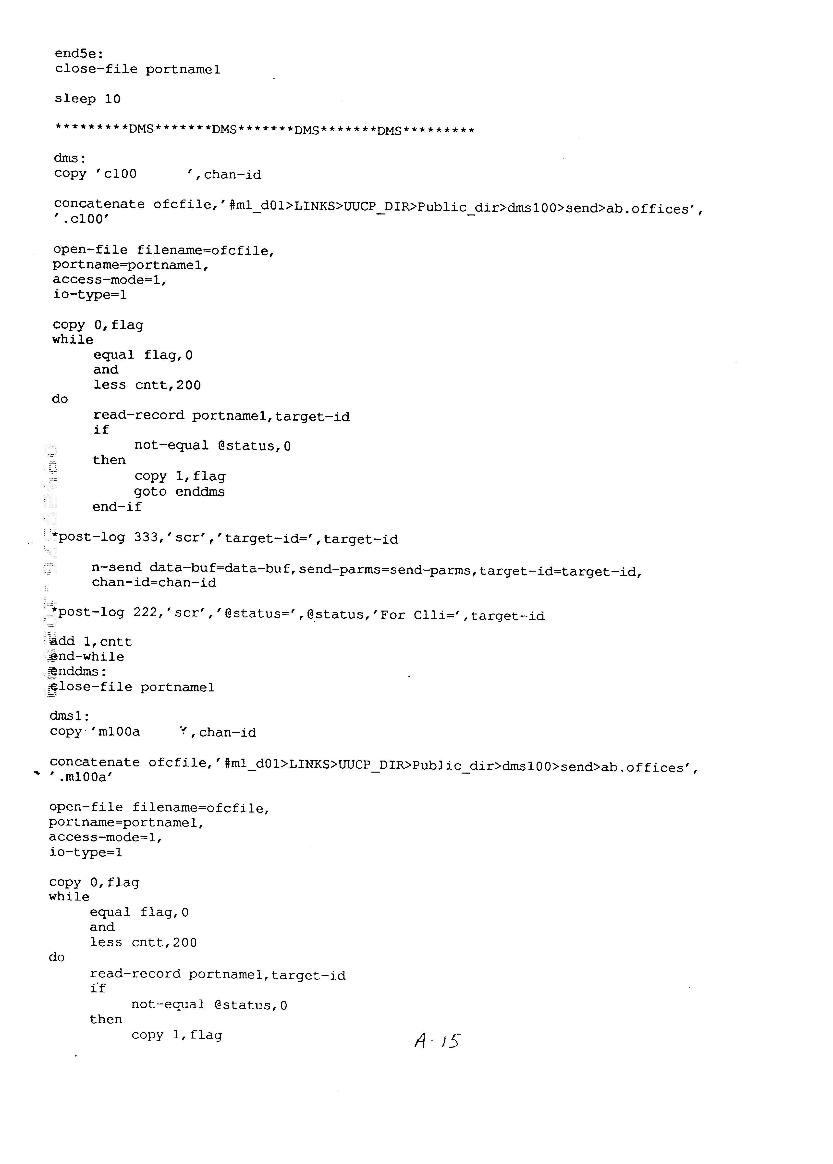
Attached hereto is a Source Code Appendix which consists of pages A-1 through A-46.
The present invention relates to a method and system for call tracing, and, more particularly, to an automated method and system for quickly and simply establishing and removing a trace on a telephone line.
Known methods and systems for establishing a trace on an identified telephone number have, in general, been cumbersome and time-consuming thereby, often wasting valuable time in a situation where time is of the essence. More particularly, some known methods and systems for establishing a trace require manually programming central office switches in a geographic area. For example, if a trace is to be established for calls originating in the Chicago area, such a task typically requires three persons about three hours each to manually perform the task. This wastes precious time in a situation, such as a kidnapping, where time can not be wasted. In addition, as with any system that requires manual programming, errors may be made which would compromise the trace and lead to valuable information being lost.
Other known call tracing methods and systems require that an incoming call actually be answered and that the answering party initiate the trace. For example, U.S. Pat. No. 4,591,665 (Foster et al.) disclose a method of providing customer originated call tracing. If a customer receives an obscene or nuisance call, for example, the customer enters a code indicating that such a call has been received. The identity of the calling party is identified to authorities in response to the action by the customer. Such a system has obvious drawbacks including the potential for abuse by a called party. Such abuse would waste valuable time on the part of the authorities and detract authorities from where their resources are most needed. Other systems use a caller identification type of tracing commonly referred to as caller i.d. U.S. Pat. No. 4,754,475 (Pintos et al.) discloses a calling line tracing system and identification detector which identifies of a calling party without the called party ever lifting the telephone receiver. Other systems forward an incoming call to a called party's pager including caller i.d.-type information. See, for example, U.S. Pat. Nos. 5,644,626 (Carlsen et al.); 5,692,038 (Kraus et al.) and 5,694,453 (Fuller et al.). A drawback with such caller i.d. type devices is that the calling party may block the identification of the calling number typically by entering a code using the keypad of a phone before a call is made.
It is thus desirable to provide a call tracing method and system that is simple to implement, significantly reduces the time for its implementation, and provides accurate information in less time than known call tracing methods and systems. It is also desirable to provide a call tracing method and system that can cancel an implemented call trace quickly. It is also desirable to provide an automated call tracing method and system that can be automatically implemented and canceled at a site remote from the switches of central offices thereby eliminating direct manual programming of the switches at the central offices. It is also desirable to provide a call tracing method and system that does not require any action by the called party.
According to a first aspect of the invention there is provided a method for tracing a call. The method includes the steps of:
(a) displaying a log-on screen on a display device, the log-on screen having a plurality of fields requiring input data including a telephone number field;
(b) inputting a telephone number in the telephone number field wherein the telephone number represents the number to be traced;
(c) establishing a call trace in a plurality of central offices;
(d) displaying a confirmation screen on the display device, the confirmation screen indicating whether the trace was successfully established or not in each of the plurality of central offices; and
(e) indicating that a call has been made to the telephone number input in step (b).
According to a second aspect of the invention there is provided a method for tracing a call. The method includes the steps of:
(a) simultaneously designating at least one telephone number to be traced in a plurality of central offices;
(b) monitoring incoming calls at said plurality of central offices;
(c) determining when an incoming call at one of said plurality of central offices matches the at least one telephone number designated in step (a); and
(d) if it is determined in step (c) that an incoming call at one of said plurality of central offices matches the at least one telephone number designated in step (a), then indicating that a match has occurred.
According to a third aspect of the invention there is provided a system for tracing calls. The system includes:
a processor;
a plurality of central offices coupled to the processor for sending messages to the processor and receiving messages from the processor;
wherein the processor is programmed to run the following call tracing routine;
receiving a message identifying a telephone number to be traced;
transmitting a command to the plurality of central offices to establish a trace on the identified telephone number;
transmitting a trace found message to a display device when any one of the plurality of central offices detects that the identified telephone number has been called.
According to a fourth aspect of the invention there is provided a call trace process performed by a computer network. The process includes the steps of:
a first party identifying a telephone number to be traced;
the first party sending a call trace activation message to the computer network authorizing the activation of a call trace, the message also including the telephone number to be traced;
the computer network sending a call trace activator message to a central office coupled to the computer network;
the central office sending a call trace found message to the computer network whenever an incoming call is matched to the telephone number to be traced;
the computer network sending a call trace information message to the first party wherein the call trace information message includes an identification of the telephone number of the incoming call.
FIG. 1 is a block diagram illustrating the various interfacing equipment of a preferred embodiment of the call tracing method and system of the present invention.
FIG. 2 is a detailed block diagram of the control office.
FIGS. 3 and 4 illustrate the command and message flow pattern between the control office and the public switched telephone network.
FIGS. 5-7 illustrate various screens that appears on a display device.
FIGS. 8 and 9 are flow charts of the call trace program according to preferred embodiments of the present invention.
FIG. 1 is a block diagram illustrating the various interfacing equipment of a preferred embodiment of the call tracing system and method of the present invention. The present invention is implemented in a preexisting telephone infrastructure. The infrastructure includes a public switched telephone network (PSTN) 10; and telephones 14, 16, 18 located at various geographic locations such as a home, office or payphone stand, respectively, coupled to the PSTN 10 so that they may communicate with one another as is well known in the art. The PSTN 10 includes central offices scattered at various geographic locations as well as other equipment which is well known to those of ordinary skill in the art. The central offices are categorized according to the telephone technology employed in the central offices. For example, central office 22 may be an EWSD type central office, central office 26 may be a DMS100 type central office and central office 28 may be a 5ESS type central office. Although one block is illustrated in FIG. 1 for each type of central office there of course would be a plurality of such offices scattered at various geographic location as is well known to those of ordinary skill in the art.
A control office 20 is also coupled to the PSTN 10. The control office 20 includes a processor 30 and a display unit 32 coupled thereto. As will be described in detail hereinafter, in this preferred embodiment it is in the control office 20 that a method for automated call tracing is implemented. The processor 30 sends messages to and receives messages from the central offices 22, 24, 26, 28 as will be described in detail hereinafter. In general, the processor 30 runs a call trace program which programs switches (not shown) in the central offices to monitor calls made to an identified number. Each central office returns a message to the processor 30 indicating whether the trace was successfully placed. When a call is made to the traced number, the central office which handles the call sends a message to the processor 30 indicating that a trace was made which includes preferably the number from which the call was placed and the central office which detected the call as well as the traced number.
FIG. 2 is a detailed block diagram of the control office 20. In a preferred embodiment the processor 30 includes a Web browser 34, an object server 36 and a network monitoring and analysis system (“NMA system”) 38. The Web browser 34 operates in an object-oriented language such as Pearl while the NMA system 38 operates in transactional language such as transactional language 1 (TL1) protocol. The object server 36 provides compatibility between the Web browser 34 and the NMA system 38 and preferably operates in an object-oriented language such as HTML or Pearl. In a preferred embodiment the processor 30 includes a Unix platform housing the Web browser 34 and object server 36 and a Stratus computer on which an application (“NMA application”) implementing the NMA system is loaded. The NMA application is available from Bellcore of New Jersey.
A call trace is preferably initiated through a Web browser page. FIGS. 3 and 4 illustrate the command and message flow pattern between the control office 20 and the PSTN 10. FIG. 3 represents the Unix platform side of the process which implements the Web browser and object server and FIG. 4 represents the Stratus computer side of the process which implements the NMA system. Beginning with FIG. 3 at block 39 an initial Web page is displayed on the display unit 32. FIG. 5 illustrates the initial Web page in the form of a log-on screen 40 that appears on the display device 32. The log-on screen 40 preferably includes a plurality of fields that either require input from the user or display output. For example, the input fields include a telephone number field 42 that requires the user to input the telephone number on which a trace is to be placed. In addition there is a geographic location field 44 which, in the preferred embodiment illustrated, indicates a choice of five states. Of course more or less states may be listed. In the geographic location field 44 the user selects which geographic area is to be monitored for incoming calls made to the traced phone number. For example, it may be desired to monitor calls made in Illinois to the traced number. The user may select one geographic area, a plurality of geographic areas or all of them depending on the desired scope of surveillance. A login field 46 and password field 48 may be provided. Once all of the required information is input by the user and the user is satisfied with the input values selected, the user clicks on a submit button 40 to begin the implementation of a call trace. A reset button 42 allows the user to clear the logon screen and re-input data. Once the user submits the information on the log-on screen a new confirmation screen appears as indicated at block 41 of FIG. 3. FIG. 6 illustrates the confirmation screen 58. The confirmation screen 58 lists the number to be traced at line 60 and the geographic area where the trace will be placed at line 62. The user has the option at the confirmation screen 58 to either activate the call trace or cancel it. If the user clicks on the correct button 46, the call trace is activated.
Returning to FIG. 3, the NMA system is continuously running a program called file13checker which gathers information entered in the log on and confirmation screens and sends that information to the NMA system as indicated at block 43. Referring to FIG. 4 at block 45 the NMA system runs a call trace program. At block 45 separate messages are created for each type of central office. For example, a DMS100 Trace Process Trace message 47 is sent to every DMS 100 central office in the geographic area selected. A EWSD Trace Process Trace message 49 is sent to every EWSD central office in the geographic area selected. A 1AESS Trace Process Trace message 51 is sent to every 1AESS control office in the geographic area selected. A 5ESS Trace Process Trace message 53 is sent to every 5ESS control office in the geographic area selected. Each of the central offices contacted returns a message 55, 57, 59 and 61 respectively to the Web server at block 63 indicating whether the trace was successful or not. The information is automatically displayed on the display unit at block 65. FIG. 7 illustrates a display screen of the returned information 100. It can be seen at lines 102 that a call trace was successfully implemented in a particular central office. At lines 104 it is indicated that a call trace was not successfully established. Different switch types may have different reasons for failing. For example, in the 1AESS central offices the 1A switch types must enter the number twice due to a problem in determining if the number is local or long distance. The number in the 1A case must be preceded with a 0 or 2 depending if it is local or long distance. The program according to a preferred embodiment of the present invention returns the results of both attempts. In the case of 5ESS central offices and the 5E switches the program needs to determine if the NPA of the 5ESS central office is the same as the NPA of the trace number and if a 7 digit number is entered into the switch. The DMS100 central office and DMS switches require a login and password and may fail this step in the process.
With the trace now in place, the central offices monitor for incoming calls made to the number placed on trace. Messages are automatically collected at the central offices, and when the traced number is called, an output message 63, 65, 67 or 69 depending on which central office detected the incoming call is passed to a trace found program. The trace found program reformats the message and sends the information to a Sfax program which generates an alphanumeric page to a security pager 71 in the following format:
“Trace found ### ### #### number called ### ### #### from XXXXXXXXXX central office.”
The pager 71 displays the message on a display screen 73 of the pager 71. The message 63, 65, 67 or 69 generated by the central office is also sent back to the Web server at block 62. The initial logon screen 40 is displayed on the display unit 32 once the call trace is activated. At line 54 it is indicated how many incoming calls have been linked to the traced number. The user clicks on line 56 to display the actual message generated by a central office. This process is repeated every time the traced number is called and a file containing the trace information is augmented with the additional messages regarding calls made to the traced number. It was found through testing that it took approximately 1 minute to complete the page from the time the traced phone began to ring. This time will vary and depends mostly on the paging company used. It was found that it takes about 5 minutes to successfully implement a trace, i.e., program the central offices. If the particularities of some of the central offices were eliminated, such as the need for entering a number twice for 1AESS switches the time to implement a trace could possibly be shortened to about 1.5 minutes.
In a preferred embodiment all the calls to the traced number are also logged with time stamps as well as sent downstream to a MACS system and may be obtained through normal tracing channels.
To cancel a call trace the user simply enters the number on which the trace was placed in line 42 of screen 40 with a “can” prefix attached to the traced number. A confirmation page similar to that shown in FIG. 6 is again returned from the central offices and displayed indicating whether the trace was successfully canceled or not.
FIGS. 8 and 9 are flow charts of the call trace program according to preferred embodiments of the present invention.
It is to be understood that the forms of the invention described herein are to be taken as preferred examples and that various changes in the shape, size and arrangement of parts may be resorted to without departing from the spirit of the invention or scope of the claims. 


Claims (23)
1. A method for tracing a call, the method comprising steps of:
in a telecommunications network, receiving a telephone number to be traced;
establishing a call trace at a plurality of central offices of the telecommunications network using the telephone number to be traced; and
on a user display device, indicating that a call has been made to the telephone number to be traced.
2. The method of claim 1 further comprising a step of:
identifying the central office of the plurality of central offices that handled the call made to the telephone number to be traced.
3. The method of claim 1 further comprising step of:
monitoring incoming calls at each central office of the plurality of central offices; and
when a called number associated with an incoming call matches the telephone number to be traced, producing an indication.
4. The method of claim 3 wherein the step of producing the indication comprises a step of:
transmitting a calling number associated with the incoming call to a control office.
5. The method of claim 1 wherein the step of establishing a call trace comprises steps of:
determining a type of central office for each central office of the plurality of central offices;
creating a message for each type of central office; and
transmitting to respective central offices the message of the type created for the respective central office.
6. The method of claim 5 wherein the step of transmitting the message comprises a step of:
transmitting the telephone number to be traced in the message.
7. A call tracing method comprising steps of:
in a telecommunications network, receiving a number to be traced;
identifying an office type for central offices of the telecommunication network;
formatting respective call trace messages in accordance with each respective office type; and
transmitting the respective call trace messages to central offices of the telecommunications network according to respective office types to establish a call trace of the number to be traced.
8. The call tracing method of claim 7 further comprising a step of:
identifying a subset of central offices of the central offices of the telecommunications network for establishing the call trace; and
formatting the respective call trace messages according to the office type of only the subset of central offices.
9. The call tracing method of claim 8 wherein identifying a subset of central offices comprises a step of:
receiving a geographic restrictor; and
including in the subset of central offices only central offices of the telecommunications network in accordance with the geographic restrictor.
10. The call tracing method of claim 7 further comprising steps of:
receiving from the central offices a response message indicating success in establishing the call trace.
11. The call tracing method of claim 7 further comprising step of:
receiving an indication from a central office when an incoming call at the central office corresponds to the number to be traced.
12. The call tracing method of claim 11 wherein receiving the indication comprises steps of:
receiving a message from the central office; and
reading a calling number from the message.
13. The call tracing method of claim 12 further comprising the step of:
in response to the indication, producing a user alert.
14. The call tracing method of claim 13 wherein producing a user alert comprises a step of:
communicating a page request to a paging service provider.
15. The call tracing method of claim 14 wherein communicating a page request comprises steps of:
communicating the calling number.
16. Apparatus for initiating a trace of a call, the apparatus comprising:
a user interface configured to receive and display information related to a telephone number to be traced wherein the user interface comprises:
a web page including a telephone number field for entry of the telephone number to be traced; and
a network access system cooperating with the user interface to establish a call trace at a plurality of central offices of the telecommunications network using the telephone number to be traced.
17. The apparatus of claim 16 wherein the web page comprises:
a telephone number field for entry of information about the telephone number to be traced.
18. The apparatus of claim 16 wherein the web page comprises:
a geographic location field for entry of information about a geographic area to be monitored for calls made to the telephone number to be traced.
19. The apparatus of claim 16 wherein the web page comprises:
a login field for entry of information associated with a user of the apparatus.
20. The apparatus of claim 19 wherein the web page comprises:
a password entry field.
21. Apparatus for initiating a trace of a call, the apparatus comprising:
a user interface configured to receive and display information related to a telephone number to be traced;
a network access system cooperating with the user interface to establish a call trace at a plurality of central offices of the telecommunications network using the telephone number to be traced; and
a processor operable in conjunction with a web browser to define the user interface.
22. The apparatus of claim 21 wherein in the user interface comprises:
an initial web page for entry of information related to the telephone number to be traced; and
a confirmation web page.
23. The apparatus of claim 22 wherein the user interface further comprises:
a results web page to display results of the trace of the call.
Priority Applications (6)
| Application Number | Priority Date | Filing Date | Title |
|---|---|---|---|
| US09/429,576 US6243458B1 (en) | 1998-04-17 | 1999-10-28 | Method and system for call tracing |
| US09/873,613 US6404882B2 (en) | 1996-11-27 | 2001-06-04 | Method and system for call tracing |
| US10/167,282 US6718031B2 (en) | 1998-04-17 | 2002-06-11 | Method and system for call tracing |
| US10/685,356 US6925164B2 (en) | 1998-04-17 | 2003-10-14 | Method and system for call tracing |
| US11/144,477 US7221751B2 (en) | 1998-04-17 | 2005-06-02 | Method and system for call tracing |
| US11/786,677 US7796746B2 (en) | 1998-04-17 | 2007-04-12 | Method and system for call tracing |
Applications Claiming Priority (2)
| Application Number | Priority Date | Filing Date | Title |
|---|---|---|---|
| US09/061,926 US5999616A (en) | 1998-04-17 | 1998-04-17 | Method and system for call tracing |
| US09/429,576 US6243458B1 (en) | 1998-04-17 | 1999-10-28 | Method and system for call tracing |
Related Parent Applications (2)
| Application Number | Title | Priority Date | Filing Date |
|---|---|---|---|
| US08/756,598 Continuation US5982867A (en) | 1996-11-27 | 1996-11-27 | Method and system for providing the name of the state of a calling party |
| US09/061,926 Continuation US5999616A (en) | 1996-11-27 | 1998-04-17 | Method and system for call tracing |
Related Child Applications (1)
| Application Number | Title | Priority Date | Filing Date |
|---|---|---|---|
| US09/873,613 Continuation US6404882B2 (en) | 1996-11-27 | 2001-06-04 | Method and system for call tracing |
Publications (1)
| Publication Number | Publication Date |
|---|---|
| US6243458B1 true US6243458B1 (en) | 2001-06-05 |
Family
ID=22039049
Family Applications (7)
| Application Number | Title | Priority Date | Filing Date |
|---|---|---|---|
| US09/061,926 Expired - Fee Related US5999616A (en) | 1996-11-27 | 1998-04-17 | Method and system for call tracing |
| US09/429,576 Expired - Lifetime US6243458B1 (en) | 1996-11-27 | 1999-10-28 | Method and system for call tracing |
| US09/873,613 Expired - Lifetime US6404882B2 (en) | 1996-11-27 | 2001-06-04 | Method and system for call tracing |
| US10/167,282 Expired - Fee Related US6718031B2 (en) | 1998-04-17 | 2002-06-11 | Method and system for call tracing |
| US10/685,356 Expired - Lifetime US6925164B2 (en) | 1998-04-17 | 2003-10-14 | Method and system for call tracing |
| US11/144,477 Expired - Fee Related US7221751B2 (en) | 1998-04-17 | 2005-06-02 | Method and system for call tracing |
| US11/786,677 Expired - Fee Related US7796746B2 (en) | 1998-04-17 | 2007-04-12 | Method and system for call tracing |
Family Applications Before (1)
| Application Number | Title | Priority Date | Filing Date |
|---|---|---|---|
| US09/061,926 Expired - Fee Related US5999616A (en) | 1996-11-27 | 1998-04-17 | Method and system for call tracing |
Family Applications After (5)
| Application Number | Title | Priority Date | Filing Date |
|---|---|---|---|
| US09/873,613 Expired - Lifetime US6404882B2 (en) | 1996-11-27 | 2001-06-04 | Method and system for call tracing |
| US10/167,282 Expired - Fee Related US6718031B2 (en) | 1998-04-17 | 2002-06-11 | Method and system for call tracing |
| US10/685,356 Expired - Lifetime US6925164B2 (en) | 1998-04-17 | 2003-10-14 | Method and system for call tracing |
| US11/144,477 Expired - Fee Related US7221751B2 (en) | 1998-04-17 | 2005-06-02 | Method and system for call tracing |
| US11/786,677 Expired - Fee Related US7796746B2 (en) | 1998-04-17 | 2007-04-12 | Method and system for call tracing |
Country Status (3)
| Country | Link |
|---|---|
| US (7) | US5999616A (en) |
| AU (1) | AU3561399A (en) |
| WO (1) | WO1999055063A1 (en) |
Cited By (4)
| Publication number | Priority date | Publication date | Assignee | Title |
|---|---|---|---|---|
| US6404882B2 (en) * | 1996-11-27 | 2002-06-11 | Ameritech Services, Inc. | Method and system for call tracing |
| US6765990B2 (en) | 2001-12-20 | 2004-07-20 | Tekelec | Database driven methods and systems for real time call tracing |
| US6771950B1 (en) * | 2000-09-12 | 2004-08-03 | Qwest Communications International Inc. | Method and system for a wireless subscriber to initiate a calling party number trace |
| US8649272B2 (en) | 2010-05-17 | 2014-02-11 | Tekelec Global, Inc. | Methods, systems and computer readable media for mobile-communication-device-initiated network monitoring services |
Families Citing this family (19)
| Publication number | Priority date | Publication date | Assignee | Title |
|---|---|---|---|---|
| FI981302A (en) * | 1998-06-08 | 1999-12-09 | Nokia Telecommunications Oy | Tracing in a mobile communication system |
| US20030131970A1 (en) * | 2002-01-17 | 2003-07-17 | Carter Daniel P. | Heat sinks and method of formation |
| US7016327B2 (en) * | 2002-08-21 | 2006-03-21 | Qualcomm Incorporated | Method and system for communicating content on a broadcast services communication system |
| US7734027B2 (en) * | 2003-06-04 | 2010-06-08 | Alcatel-Lucent Usa Inc. | Call control component collection of communication device identification information for internet protocol endpoint |
| US7417981B2 (en) * | 2003-10-15 | 2008-08-26 | Vonage Holdings Corp. | Method and apparatus for enhanced Internet Telephony |
| US7386111B2 (en) * | 2004-02-10 | 2008-06-10 | Vonage Network Inc. | Method and apparatus for placing a long distance call based on a virtual phone number |
| US20060210036A1 (en) | 2005-03-16 | 2006-09-21 | Jeffrey Citron | System for effecting a telephone call over a computer network without alphanumeric keypad operation |
| US20060210040A1 (en) * | 2005-03-16 | 2006-09-21 | Jeffrey Citron | Transfer identification software enabling electronic communication system |
| US8683044B2 (en) * | 2005-03-16 | 2014-03-25 | Vonage Network Llc | Third party call control application program interface |
| WO2007047413A2 (en) * | 2005-10-13 | 2007-04-26 | Vonage Holdings Corp. | Method and system for detecting a change in device attachment |
| MX2008006172A (en) * | 2005-11-09 | 2008-10-09 | Vonage Holdings Corp | Method and system for customized caller identification. |
| US20070274074A1 (en) * | 2006-02-01 | 2007-11-29 | Smires Daniel T | Method and apparatus for communicating a status of a device in a packet-based communication network |
| US8917717B2 (en) * | 2007-02-13 | 2014-12-23 | Vonage Network Llc | Method and system for multi-modal communications |
| CN101390337B (en) * | 2006-02-27 | 2011-09-28 | 沃纳格控股公司 | Automatic device configuration |
| US20070226701A1 (en) * | 2006-03-23 | 2007-09-27 | Nokia Corporation | Automated central trace management |
| US20080031259A1 (en) * | 2006-08-01 | 2008-02-07 | Sbc Knowledge Ventures, Lp | Method and system for replicating traffic at a data link layer of a router |
| TWI386021B (en) * | 2007-08-07 | 2013-02-11 | Chunghwa Telecom Co Ltd | Dispersed call tracking screens with versatile characters and reliability Methods and systems |
| US9757542B2 (en) | 2012-05-17 | 2017-09-12 | Lake Region Manufacturing, Inc. | Capture device |
| US20150163348A1 (en) * | 2013-12-05 | 2015-06-11 | Genband Us Llc | Debug Line Tracer |
Citations (15)
| Publication number | Priority date | Publication date | Assignee | Title |
|---|---|---|---|---|
| US3795774A (en) * | 1971-12-09 | 1974-03-05 | E Talbot | Telephone communication system with auxiliary unit for call tracing |
| US3904830A (en) * | 1972-07-03 | 1975-09-09 | Mek Tronix Lab | Call tracing and identification system |
| US3997732A (en) * | 1972-07-03 | 1976-12-14 | Mek-Tronix Laboratories Corporation | Call tracing and identification system |
| US4464543A (en) * | 1982-12-01 | 1984-08-07 | Gte Business Communication Systems Inc. | Network control center call trace |
| US4591665A (en) | 1983-07-12 | 1986-05-27 | At&T Bell Laboratories | Method and apparatus for providing call tracing service |
| US4754475A (en) | 1981-10-02 | 1988-06-28 | Sonintel Sociedade Nacional De Industria De Telecomunicacoes Ltda. | Calling line tracing system and identification detector |
| US4914689A (en) | 1987-12-22 | 1990-04-03 | Bell Mountain States Telephone & Telegraph Co. | Reverse automatic number identification system |
| US5546448A (en) | 1994-11-10 | 1996-08-13 | Multi-Tech Systems, Inc. | Apparatus and method for a caller ID modem interface |
| US5644626A (en) | 1992-02-28 | 1997-07-01 | At&T | Apparatus and method for connecting telephone calls using automated paging and call bridging |
| US5659604A (en) * | 1995-09-29 | 1997-08-19 | Mci Communications Corp. | System and method for tracing a call through a telecommunications network |
| US5668852A (en) | 1995-01-18 | 1997-09-16 | Holmes; Terry M. | Automatic caller-associated information provision system, improvement and method for paging system |
| US5692038A (en) | 1992-08-26 | 1997-11-25 | Bellsouth Corporation | Method for identifying the source of a telephonic communication |
| US5694453A (en) | 1984-09-14 | 1997-12-02 | Accessline Technologies, Inc. | Method and apparatus for processing telephone calls and delivering information about the calls to a pager |
| US5844522A (en) * | 1995-10-13 | 1998-12-01 | Trackmobile, Inc. | Mobile telephone location system and method |
| US5930344A (en) * | 1997-10-14 | 1999-07-27 | At & T Corp. | Method and apparatus for tracing a specific communication |
Family Cites Families (3)
| Publication number | Priority date | Publication date | Assignee | Title |
|---|---|---|---|---|
| US5761280A (en) * | 1996-09-04 | 1998-06-02 | 8×8, Inc. | Telephone web browser arrangement and method |
| US5999616A (en) * | 1998-04-17 | 1999-12-07 | Ameritech Services, Inc. | Method and system for call tracing |
| US6286050B1 (en) * | 1997-01-27 | 2001-09-04 | Alcatel Usa Sourcing, L.P. | System and method for monitoring and management of telecommunications equipment using enhanced internet access |
-
1998
- 1998-04-17 US US09/061,926 patent/US5999616A/en not_active Expired - Fee Related
-
1999
- 1999-04-15 WO PCT/US1999/008210 patent/WO1999055063A1/en active Application Filing
- 1999-04-15 AU AU35613/99A patent/AU3561399A/en not_active Abandoned
- 1999-10-28 US US09/429,576 patent/US6243458B1/en not_active Expired - Lifetime
-
2001
- 2001-06-04 US US09/873,613 patent/US6404882B2/en not_active Expired - Lifetime
-
2002
- 2002-06-11 US US10/167,282 patent/US6718031B2/en not_active Expired - Fee Related
-
2003
- 2003-10-14 US US10/685,356 patent/US6925164B2/en not_active Expired - Lifetime
-
2005
- 2005-06-02 US US11/144,477 patent/US7221751B2/en not_active Expired - Fee Related
-
2007
- 2007-04-12 US US11/786,677 patent/US7796746B2/en not_active Expired - Fee Related
Patent Citations (15)
| Publication number | Priority date | Publication date | Assignee | Title |
|---|---|---|---|---|
| US3795774A (en) * | 1971-12-09 | 1974-03-05 | E Talbot | Telephone communication system with auxiliary unit for call tracing |
| US3904830A (en) * | 1972-07-03 | 1975-09-09 | Mek Tronix Lab | Call tracing and identification system |
| US3997732A (en) * | 1972-07-03 | 1976-12-14 | Mek-Tronix Laboratories Corporation | Call tracing and identification system |
| US4754475A (en) | 1981-10-02 | 1988-06-28 | Sonintel Sociedade Nacional De Industria De Telecomunicacoes Ltda. | Calling line tracing system and identification detector |
| US4464543A (en) * | 1982-12-01 | 1984-08-07 | Gte Business Communication Systems Inc. | Network control center call trace |
| US4591665A (en) | 1983-07-12 | 1986-05-27 | At&T Bell Laboratories | Method and apparatus for providing call tracing service |
| US5694453A (en) | 1984-09-14 | 1997-12-02 | Accessline Technologies, Inc. | Method and apparatus for processing telephone calls and delivering information about the calls to a pager |
| US4914689A (en) | 1987-12-22 | 1990-04-03 | Bell Mountain States Telephone & Telegraph Co. | Reverse automatic number identification system |
| US5644626A (en) | 1992-02-28 | 1997-07-01 | At&T | Apparatus and method for connecting telephone calls using automated paging and call bridging |
| US5692038A (en) | 1992-08-26 | 1997-11-25 | Bellsouth Corporation | Method for identifying the source of a telephonic communication |
| US5546448A (en) | 1994-11-10 | 1996-08-13 | Multi-Tech Systems, Inc. | Apparatus and method for a caller ID modem interface |
| US5668852A (en) | 1995-01-18 | 1997-09-16 | Holmes; Terry M. | Automatic caller-associated information provision system, improvement and method for paging system |
| US5659604A (en) * | 1995-09-29 | 1997-08-19 | Mci Communications Corp. | System and method for tracing a call through a telecommunications network |
| US5844522A (en) * | 1995-10-13 | 1998-12-01 | Trackmobile, Inc. | Mobile telephone location system and method |
| US5930344A (en) * | 1997-10-14 | 1999-07-27 | At & T Corp. | Method and apparatus for tracing a specific communication |
Non-Patent Citations (3)
| Title |
|---|
| Advanced Custom Calling Features, "North Pittsburgh Telephone Company," (Jan., 1998) (2 pages). |
| Call Trace, "Crosslake Telephone & Cablevision Company," (Jan., 1998) (1 page). |
| Tame Your Telephone. . . with Advanced Calling Services from VTCI, "VTCI Advanced Calling Services," (Jan., 1998) (1 page). |
Cited By (11)
| Publication number | Priority date | Publication date | Assignee | Title |
|---|---|---|---|---|
| US6404882B2 (en) * | 1996-11-27 | 2002-06-11 | Ameritech Services, Inc. | Method and system for call tracing |
| US6718031B2 (en) * | 1998-04-17 | 2004-04-06 | Ameritech Services, Inc. | Method and system for call tracing |
| US20040146155A1 (en) * | 1998-04-17 | 2004-07-29 | Ameritech Services, Inc. | Method and system for call tracing |
| US6925164B2 (en) * | 1998-04-17 | 2005-08-02 | Ameritech Services, Inc. | Method and system for call tracing |
| US20050226402A1 (en) * | 1998-04-17 | 2005-10-13 | Ameritech Services, Inc. | Method and system for call tracing |
| US7221751B2 (en) * | 1998-04-17 | 2007-05-22 | Ameritech Services, Inc. | Method and system for call tracing |
| US20090147927A1 (en) * | 1998-04-17 | 2009-06-11 | Ameritech Services, Inc. | Method and system for call tracing |
| US7796746B2 (en) * | 1998-04-17 | 2010-09-14 | At&T Intellectual Property I, L.P. | Method and system for call tracing |
| US6771950B1 (en) * | 2000-09-12 | 2004-08-03 | Qwest Communications International Inc. | Method and system for a wireless subscriber to initiate a calling party number trace |
| US6765990B2 (en) | 2001-12-20 | 2004-07-20 | Tekelec | Database driven methods and systems for real time call tracing |
| US8649272B2 (en) | 2010-05-17 | 2014-02-11 | Tekelec Global, Inc. | Methods, systems and computer readable media for mobile-communication-device-initiated network monitoring services |
Also Published As
| Publication number | Publication date |
|---|---|
| US7796746B2 (en) | 2010-09-14 |
| US20040146155A1 (en) | 2004-07-29 |
| US6925164B2 (en) | 2005-08-02 |
| AU3561399A (en) | 1999-11-08 |
| US20090147927A1 (en) | 2009-06-11 |
| US20030007607A1 (en) | 2003-01-09 |
| US20050226402A1 (en) | 2005-10-13 |
| WO1999055063A1 (en) | 1999-10-28 |
| US20020041672A1 (en) | 2002-04-11 |
| US5999616A (en) | 1999-12-07 |
| US7221751B2 (en) | 2007-05-22 |
| US6718031B2 (en) | 2004-04-06 |
| US6404882B2 (en) | 2002-06-11 |
Similar Documents
| Publication | Publication Date | Title |
|---|---|---|
| US7796746B2 (en) | Method and system for call tracing | |
| US6801780B1 (en) | Method and apparatus for providing intelligent emergency paging | |
| US6993014B2 (en) | Method and apparatus for allowing selective disposition of an incoming telephone call during an internet session | |
| US6192123B1 (en) | Method and apparatus for initiating telephone calls using a data network | |
| EP0701381B1 (en) | Method and telephone for determining the features assigned to a telephone subscriber | |
| US5946381A (en) | Controlling incoming calls via the world-wide web | |
| US5339351A (en) | Emergency response system | |
| US6735614B1 (en) | Contact alerts for unconnected users | |
| US6810419B1 (en) | Device for operating a network management system | |
| CA2161506C (en) | File retrieval with incoming calls | |
| EP0920178A2 (en) | Monitoring charges for network services | |
| US20070195942A1 (en) | Systems and Methods for Providing User Profile Information in Conjunction with an Enhanced Caller Information System | |
| EP1131947A1 (en) | Method and system for communicating caller identification information between a remote site and a central monitoring station over pstn | |
| US5596632A (en) | Message-based interface for phone fraud system | |
| US5937034A (en) | Method for testing call waiting, caller ID functionality of telephone line | |
| US6018577A (en) | Data messaging method | |
| US6445783B1 (en) | System and method that provides specialized processing of communications based on automatically generated identifiers | |
| JP2001313720A (en) | Method for confirming personal information in electronic commercial transaction system | |
| CA2240036A1 (en) | Credit status checking system for transaction processing system and checking method therefor | |
| US6400811B1 (en) | System and method for off-line notifying a network user | |
| KR19980703452A (en) | Monitoring method of object through digital data network | |
| AU772259B2 (en) | Selecting IPX/IGX nodes in a multi-domain environment | |
| JP3482565B2 (en) | Information communication system | |
| US20010017911A1 (en) | Procedure and system for executing an alarm function | |
| JP3322787B2 (en) | PBX-computer interlocking system |
Legal Events
| Date | Code | Title | Description |
|---|---|---|---|
| STCF | Information on status: patent grant |
Free format text: PATENTED CASE |
|
| FPAY | Fee payment |
Year of fee payment: 4 |
|
| FPAY | Fee payment |
Year of fee payment: 8 |
|
| FPAY | Fee payment |
Year of fee payment: 12 |