US6238958B1 - Method for forming a transistor with reduced source/drain series resistance - Google Patents
Method for forming a transistor with reduced source/drain series resistance Download PDFInfo
- Publication number
- US6238958B1 US6238958B1 US09/477,109 US47710999A US6238958B1 US 6238958 B1 US6238958 B1 US 6238958B1 US 47710999 A US47710999 A US 47710999A US 6238958 B1 US6238958 B1 US 6238958B1
- Authority
- US
- United States
- Prior art keywords
- layer
- silicon
- epi
- drain region
- spacer
- Prior art date
- Legal status (The legal status is an assumption and is not a legal conclusion. Google has not performed a legal analysis and makes no representation as to the accuracy of the status listed.)
- Expired - Fee Related
Links
- 238000000034 method Methods 0.000 title claims abstract description 70
- 239000004020 conductor Substances 0.000 claims abstract description 28
- 239000000758 substrate Substances 0.000 claims abstract description 28
- 229910052710 silicon Inorganic materials 0.000 claims abstract description 25
- 239000010703 silicon Substances 0.000 claims abstract description 25
- 125000006850 spacer group Chemical group 0.000 claims abstract description 17
- 229920002120 photoresistant polymer Polymers 0.000 claims abstract description 12
- 150000002500 ions Chemical class 0.000 claims abstract description 9
- 229910021420 polycrystalline silicon Inorganic materials 0.000 claims description 14
- 238000005468 ion implantation Methods 0.000 claims description 9
- 239000002184 metal Substances 0.000 claims description 7
- 229910052751 metal Inorganic materials 0.000 claims description 7
- 229910052581 Si3N4 Inorganic materials 0.000 claims description 6
- HQVNEWCFYHHQES-UHFFFAOYSA-N silicon nitride Chemical compound N12[Si]34N5[Si]62N3[Si]51N64 HQVNEWCFYHHQES-UHFFFAOYSA-N 0.000 claims description 6
- 230000003647 oxidation Effects 0.000 claims description 3
- 238000007254 oxidation reaction Methods 0.000 claims description 3
- 238000004519 manufacturing process Methods 0.000 claims description 2
- 229910021332 silicide Inorganic materials 0.000 claims description 2
- FVBUAEGBCNSCDD-UHFFFAOYSA-N silicide(4-) Chemical compound [Si-4] FVBUAEGBCNSCDD-UHFFFAOYSA-N 0.000 claims description 2
- 238000000151 deposition Methods 0.000 claims 3
- 230000008021 deposition Effects 0.000 claims 2
- 238000005137 deposition process Methods 0.000 claims 2
- 238000000137 annealing Methods 0.000 abstract description 3
- 238000005229 chemical vapour deposition Methods 0.000 description 11
- XUIMIQQOPSSXEZ-UHFFFAOYSA-N Silicon Chemical compound [Si] XUIMIQQOPSSXEZ-UHFFFAOYSA-N 0.000 description 8
- 238000005530 etching Methods 0.000 description 4
- 238000007796 conventional method Methods 0.000 description 2
- 230000000694 effects Effects 0.000 description 2
- 238000002955 isolation Methods 0.000 description 2
- 230000004048 modification Effects 0.000 description 2
- 238000012986 modification Methods 0.000 description 2
- 239000004065 semiconductor Substances 0.000 description 2
- 230000001012 protector Effects 0.000 description 1
Images


Classifications
-
- H—ELECTRICITY
- H01—ELECTRIC ELEMENTS
- H01L—SEMICONDUCTOR DEVICES NOT COVERED BY CLASS H10
- H01L29/00—Semiconductor devices adapted for rectifying, amplifying, oscillating or switching, or capacitors or resistors with at least one potential-jump barrier or surface barrier, e.g. PN junction depletion layer or carrier concentration layer; Details of semiconductor bodies or of electrodes thereof ; Multistep manufacturing processes therefor
- H01L29/66—Types of semiconductor device ; Multistep manufacturing processes therefor
- H01L29/66007—Multistep manufacturing processes
- H01L29/66075—Multistep manufacturing processes of devices having semiconductor bodies comprising group 14 or group 13/15 materials
- H01L29/66227—Multistep manufacturing processes of devices having semiconductor bodies comprising group 14 or group 13/15 materials the devices being controllable only by the electric current supplied or the electric potential applied, to an electrode which does not carry the current to be rectified, amplified or switched, e.g. three-terminal devices
- H01L29/66409—Unipolar field-effect transistors
- H01L29/66477—Unipolar field-effect transistors with an insulated gate, i.e. MISFET
- H01L29/665—Unipolar field-effect transistors with an insulated gate, i.e. MISFET using self aligned silicidation, i.e. salicide
-
- H—ELECTRICITY
- H01—ELECTRIC ELEMENTS
- H01L—SEMICONDUCTOR DEVICES NOT COVERED BY CLASS H10
- H01L29/00—Semiconductor devices adapted for rectifying, amplifying, oscillating or switching, or capacitors or resistors with at least one potential-jump barrier or surface barrier, e.g. PN junction depletion layer or carrier concentration layer; Details of semiconductor bodies or of electrodes thereof ; Multistep manufacturing processes therefor
- H01L29/40—Electrodes ; Multistep manufacturing processes therefor
- H01L29/41—Electrodes ; Multistep manufacturing processes therefor characterised by their shape, relative sizes or dispositions
- H01L29/417—Electrodes ; Multistep manufacturing processes therefor characterised by their shape, relative sizes or dispositions carrying the current to be rectified, amplified or switched
- H01L29/41725—Source or drain electrodes for field effect devices
- H01L29/41775—Source or drain electrodes for field effect devices characterised by the proximity or the relative position of the source or drain electrode and the gate electrode, e.g. the source or drain electrode separated from the gate electrode by side-walls or spreading around or above the gate electrode
- H01L29/41783—Raised source or drain electrodes self aligned with the gate
Definitions
- the present invention relates to the method for fabricating a semiconductor device. More particularly, the present invention relates to the method for fabricating a transistor in integrated circuits.
- a transistor of integrated circuits is fabricated by the following method.
- a silicon substrate 11 is provided.
- a shallow trench isolation (STI) 12 is formed on the substrate 11 by any conventional process
- a well (n-type or p-type) 13 is formed on and in the substrate 11 by ion implantation or by any other conventional process.
- a gate oxide layer 14 is then formed on the substrate by rapid thermal oxidation (RTO) or any other conventional process.
- RTO rapid thermal oxidation
- a poly-silicon layer 15 is formed on the gate oxide layer 14 by chemical vapor deposition (CVD).
- CVD chemical vapor deposition
- an etch process is used to etch the poly-silicon layer 15 and the gate oxide layer 14 .
- the pattern having the pattern of a gate region, serves as an etching mask to protect the underlying portion of the etched layers.
- the photoresist 16 is stripped away.
- the residual poly-silicon layer 15 serves as a gate electrode of a gate in the semiconductor transistor.
- the poly-silicon layer 15 has a sidewall formed after an etch process.
- the next step is to introduce ions onto and into the substrate 11 by an ion implantation process to form a lightly doped drain (LDD) region 17 .
- LDD lightly doped drain
- CVD chemical vapor deposition
- oxide liner layer 18 is formed on all surfaces including the top and sidewall of the poly-silicon layer 15 , and the top of the substrate 11 .
- a silicon nitride layer 19 is deposited on the oxide liner layer 18 by a chemical vapor deposition (CVD) process and then etched back.
- the residual silicon nitride layer 19 serves as a spacer against the conductor layer 15 and is about 1000 angstroms thick. Then, ion implantation is used to introduce ions into the lightly doped drain (LDD) region 17 of the substrate 11 to form a source/drain region 20 .
- LDD lightly doped drain
- the exposed silicon surfaces including the top of the gate electrode 15 and the top of the substrate 11 , are treated by a salicidation process.
- the salicide layer 21 is then completed.
- the salicide layer 21 is used to reduce the resistance of the silicon surfaces and to facilitate the contact process.
- the series resistance includes a pair of contact resistance R c , a channel resistance R ch and a pair of extra resistance R ext .
- the contact resistance R c part due to nature of salicide, extends from the site at which the node contact is located to the edge of the salicide layer 21 against the nitride spacer 19 .
- the channel resistance R ch part existing in the channel region under the gate, extends from edge of the source LDD region to the one of the drain LDD region.
- the extra resistance R ext existing inside of the LDD region, is located under the nitride spacer (about 1000 angstroms).
- the effects of the series resistance is becoming more and more obvious and can be less and less ignored for the device's driving current.
- the effects include reducing the running speed of integrated circuits and causing a high temperature during running.
- a method for forming a transistor with less series resistance that substantially enhances the running speed of integrated circuits and reduces their running temperature.
- a silicon substrate is first provided.
- a gate oxide layer is then formed on the substrate.
- a conductor layer such as poly-silicon, is formed on the gate oxide layer.
- a patterned photoresist layer is formed on the poly-silicon layer.
- an etch process is used to etch the poly-silicon layer which has a sidewall.
- the patterned photoresist layer is then removed by stripping process.
- a lightly doped drain is formed on and in the substrate by ion implantation.
- a spacer is formed on the liner layer. Thereafter, an appropriate process is used to introduce ions into the lightly doped drain, and then a source/drain region is completed. The steps which follow are annealing the source/drain region and removing the spacer. Subsequently, an epi-silicon layer is formed on the lightly doped drain region, the source/drain region and the top surface of the poly-silicon layer. Finally, the epi-silicon layer is treated with a salicidation process to form a salicide layer.
- the transistor fabricated by the present invention has less series resistance than transistors fabricated by conventional methods, and will not suffer increased temperatures during running the integrated circuits.
- FIGS. 1-5 show the steps of fabricating a transistor according to conventional methods.
- FIG. 6 shows mainly the resistance parts in the non-salicide region, including a R ch and a pair of R ext ;
- FIGS. 7-13 show the steps of fabricating a transistor according to the present invention.
- FIG. 14 shows mainly that the R ext is almost canceled when the present invention is utilized.
- the extra resistance R ext (in the LDD under the conventional spacer) is very high according to known technology.
- the present invention provides a method for manufacturing a transistor in integrated circuits to solve the problem, which is described below.
- a substrate 101 such as a silicon substrate is provided.
- a shallow trench isolation (STI) 102 is formed on the substrate 101 by any conventional process to isolate any two different active areas.
- a well (n-type or p-type) 103 is formed on and in the substrate 101 by ion implantation or by any other conventional process.
- a gate oxide layer 104 is formed on the substrate by thermal oxidation or by any other conventional process.
- a conductor layer 105 such as poly-silicon, silicide or metal, is formed on the gate oxide layer 104 by chemical vapor deposition (CVD).
- CVD chemical vapor deposition
- etch process is used to etch the conductor layer 105 and the gate oxide layer 104 .
- the patterned photoresist 106 having the pattern of a gate region, serves as an etching mask to protect the underlying portion of the etched layers.
- the photoresist 106 is stripped away.
- the residual conductor layer 105 serves as a gate electrode of a gate in the transistor.
- the conductor layer 105 has a sidewall after etching.
- the next step is to form a liner layer on the sidewall of the conductor layer 105 .
- a silicon nitride layer 107 is deposited on all surfaces of the conductor layer 105 and the substrate 101 , and is then etched back.
- the silicon nitride layer 107 now etched back, is about 100-300 angstroms thick. Subsequently, an ion implantation process is used to introduce ions onto and into the substrate 101 to form a lightly doped drain (LDD) region 108 .
- LDD lightly doped drain
- the etched conductor layer 105 and the silicon nitride layer are used as a mask.
- an oxide layer 109 is deposited on all surfaces, including the top of the conductor layer 105 , the surface of the liner layer 107 and the top of the substrate 101 .
- the oxide layer 109 can be formed by a chemical vapor deposition process.
- an etch back process is used to etch back the oxide layer 109 .
- the etched back oxide layer serves as a spacer against the conductor layer 105 .
- ion implantation or any other conventional process and an annealing process are used to introduce ions (n- or p-type) into the LDD region 108 of the substrate 101 to form a source/drain region 110 .
- the implanted ions have the same kind of charge as the LDD region.
- the oxide spacer 109 is removed by stripping or etching or any other appropriate process.
- the removing process generally employs HF.
- the oxide spacer 109 is used just to protect the underlying portion of the LDD region from forming the source/drain region.
- a selective epi-silicon layer 111 is first deposited on all silicon surfaces, such as on the top of the silicon substrate 101 and the top of the conductor layer 105 (when poly-silicon is chosen).
- the epi-silicon layer should be treated with a salicidation process such that a metal 112 such as Ti or Co is formed on the epi-silicon layer 111 by chemical vapor deposition (CVD).
- CVD chemical vapor deposition
- a thermal process is then used to diffuse the metal 112 into the epi-silicon layer 111 to finally complete a salicide layer 113 as shown in FIG. 13 .
- members of the series resistance formed by the present invention are mainly illustrated.
- a pair of contact resistance R c and a channel resistance R ch are indicated.
- the length of the region under the “protector” of the gate electrode, such as the liner layer mentioned above is shorter than the prior art.
- the extra resistance R ext is almost canceled due to the modification using only the liner layer instead of both the liner layer and the spacer according to previously known technology. The whole series resistance is thus reduced.
Abstract
A method for forming a transistor in integrated circuits is disclosed. The method includes the following steps. A substrate is first provided. An insulating layer is then formed on the substrate. A conductor layer is formed on the insulating layer. Subsequently, a patterned photoresist layer is formed on the conductor layer. Next, an etch process is used to etch the conductor layer which has a sidewall. The patterned photoresist layer is then removed. After forming a liner layer on the sidewall of the conductor layer, a lightly doped drain is formed on and in the substrate. Then, a spacer is formed on the liner layer. Thereafter, a proper process is used to introduce ions into the lightly doped drain, and then a source/drain region is completed. The steps with follow include annealing the source/drain region and removing the spacer. Subsequently, an epi-silicon layer is formed on the lightly doped drain region, the source/drain region and the top surface of the conductor layer. Finally, the epi-silicon layer is treated with a salicidation process to form a salicide layer.
Description
1. Field of the Invention
The present invention relates to the method for fabricating a semiconductor device. More particularly, the present invention relates to the method for fabricating a transistor in integrated circuits.
2. Description of the Prior Art
According to conventional knowledge, a transistor of integrated circuits is fabricated by the following method.
Referring to FIG. 1, first, a silicon substrate 11 is provided. Then after a shallow trench isolation (STI) 12 is formed on the substrate 11 by any conventional process, a well (n-type or p-type) 13 is formed on and in the substrate 11 by ion implantation or by any other conventional process. A gate oxide layer 14 is then formed on the substrate by rapid thermal oxidation (RTO) or any other conventional process. Subsequently, a poly-silicon layer 15 is formed on the gate oxide layer 14 by chemical vapor deposition (CVD). After forming a patterned photoresist 16 on the poly-silicon layer 15, an etch process is used to etch the poly-silicon layer 15 and the gate oxide layer 14. Therein the pattern, having the pattern of a gate region, serves as an etching mask to protect the underlying portion of the etched layers. Thereafter, the photoresist 16 is stripped away. The residual poly-silicon layer 15 serves as a gate electrode of a gate in the semiconductor transistor.
Referring to FIG. 2, the poly-silicon layer 15 has a sidewall formed after an etch process. The next step is to introduce ions onto and into the substrate 11 by an ion implantation process to form a lightly doped drain (LDD) region 17.
Referring to FIG. 3, chemical vapor deposition (CVD) or another appropriate process is used to form an oxide liner layer 18 on all surfaces including the top and sidewall of the poly-silicon layer 15, and the top of the substrate 11. Subsequently, a silicon nitride layer 19 is deposited on the oxide liner layer 18 by a chemical vapor deposition (CVD) process and then etched back.
Referring to FIG. 4, the residual silicon nitride layer 19 serves as a spacer against the conductor layer 15 and is about 1000 angstroms thick. Then, ion implantation is used to introduce ions into the lightly doped drain (LDD) region 17 of the substrate 11 to form a source/drain region 20.
Referring to FIG. 5, the exposed silicon surfaces, including the top of the gate electrode 15 and the top of the substrate 11, are treated by a salicidation process. The salicide layer 21 is then completed.
Referring to FIG. 6, the salicide layer 21 is used to reduce the resistance of the silicon surfaces and to facilitate the contact process. In the use of the transistor structure fabricated by this convention method, at least a series resistance appears in the path through which the current is conducted. The series resistance includes a pair of contact resistance Rc, a channel resistance Rch and a pair of extra resistance Rext. The contact resistance Rc part, due to nature of salicide, extends from the site at which the node contact is located to the edge of the salicide layer 21 against the nitride spacer 19. The channel resistance Rch part, existing in the channel region under the gate, extends from edge of the source LDD region to the one of the drain LDD region. And the extra resistance Rext, existing inside of the LDD region, is located under the nitride spacer (about 1000 angstroms).
According to the trend of reducing the size of integrated circuits, the effects of the series resistance is becoming more and more obvious and can be less and less ignored for the device's driving current. The effects include reducing the running speed of integrated circuits and causing a high temperature during running.
For the foregoing reasons described above, there is a need to develop a method for fabricating a transistor that can reduce the series resistance, particularly the part of the series resistance in the non-salicide region. This improvement would enable the running speed of the integrated circuits to be enhanced, thus the increased temperature during running can be reduced.
In accordance with the present invention, a method is provided for forming a transistor with less series resistance that substantially enhances the running speed of integrated circuits and reduces their running temperature. In one embodiment, a silicon substrate is first provided. A gate oxide layer is then formed on the substrate. A conductor layer, such as poly-silicon, is formed on the gate oxide layer. Subsequently, a patterned photoresist layer is formed on the poly-silicon layer. Next, an etch process is used to etch the poly-silicon layer which has a sidewall. The patterned photoresist layer is then removed by stripping process. After forming a liner layer on the sidewall of the poly-silicon layer, a lightly doped drain is formed on and in the substrate by ion implantation. Then, a spacer is formed on the liner layer. Thereafter, an appropriate process is used to introduce ions into the lightly doped drain, and then a source/drain region is completed. The steps which follow are annealing the source/drain region and removing the spacer. Subsequently, an epi-silicon layer is formed on the lightly doped drain region, the source/drain region and the top surface of the poly-silicon layer. Finally, the epi-silicon layer is treated with a salicidation process to form a salicide layer.
The transistor fabricated by the present invention has less series resistance than transistors fabricated by conventional methods, and will not suffer increased temperatures during running the integrated circuits.
The foregoing aspects and many of the attendant advantages of the present invention will become more readily appreciated as the same becomes better understood by reference to the following detailed description, when taken in conjunction with the accompanying drawings, wherein:
FIGS. 1-5 show the steps of fabricating a transistor according to conventional methods.
FIG. 6 shows mainly the resistance parts in the non-salicide region, including a Rch and a pair of Rext;
FIGS. 7-13 show the steps of fabricating a transistor according to the present invention; and
FIG. 14 shows mainly that the Rext is almost canceled when the present invention is utilized.
The extra resistance Rext (in the LDD under the conventional spacer) is very high according to known technology. The present invention provides a method for manufacturing a transistor in integrated circuits to solve the problem, which is described below.
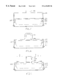
Referring to FIG. 7, first, a substrate 101 such as a silicon substrate is provided. Then a shallow trench isolation (STI) 102 is formed on the substrate 101 by any conventional process to isolate any two different active areas. A well (n-type or p-type) 103 is formed on and in the substrate 101 by ion implantation or by any other conventional process. A gate oxide layer 104 is formed on the substrate by thermal oxidation or by any other conventional process. Subsequently, a conductor layer 105, such as poly-silicon, silicide or metal, is formed on the gate oxide layer 104 by chemical vapor deposition (CVD). After forming a patterned photoresist 106 on the conductor layer 105, an etch process is used to etch the conductor layer 105 and the gate oxide layer 104. Therein the patterned photoresist 106, having the pattern of a gate region, serves as an etching mask to protect the underlying portion of the etched layers. Thereafter, the photoresist 106 is stripped away. The residual conductor layer 105 serves as a gate electrode of a gate in the transistor.
As shown in FIG. 8, the conductor layer 105 has a sidewall after etching. The next step is to form a liner layer on the sidewall of the conductor layer 105. A silicon nitride layer 107 is deposited on all surfaces of the conductor layer 105 and the substrate 101, and is then etched back.
Referring to FIG. 9, the silicon nitride layer 107, now etched back, is about 100-300 angstroms thick. Subsequently, an ion implantation process is used to introduce ions onto and into the substrate 101 to form a lightly doped drain (LDD) region 108. The etched conductor layer 105 and the silicon nitride layer are used as a mask.
Referring to FIG. 10, an oxide layer 109 is deposited on all surfaces, including the top of the conductor layer 105, the surface of the liner layer 107 and the top of the substrate 101. The oxide layer 109 can be formed by a chemical vapor deposition process.
Referring to FIG. 11, an etch back process is used to etch back the oxide layer 109. The etched back oxide layer serves as a spacer against the conductor layer 105. Then, ion implantation or any other conventional process and an annealing process are used to introduce ions (n- or p-type) into the LDD region 108 of the substrate 101 to form a source/drain region 110. The implanted ions have the same kind of charge as the LDD region. Subsequently, the oxide spacer 109 is removed by stripping or etching or any other appropriate process. Moreover, at this point, the removing process generally employs HF. According to the present invention, the oxide spacer 109 is used just to protect the underlying portion of the LDD region from forming the source/drain region.
Referring to FIG. 12, to form a salicide layer on all silicon surfaces, a selective epi-silicon layer 111, about 300-1000 angstroms thick, is first deposited on all silicon surfaces, such as on the top of the silicon substrate 101 and the top of the conductor layer 105 (when poly-silicon is chosen). Next, the epi-silicon layer should be treated with a salicidation process such that a metal 112 such as Ti or Co is formed on the epi-silicon layer 111 by chemical vapor deposition (CVD). A thermal process is then used to diffuse the metal 112 into the epi-silicon layer 111 to finally complete a salicide layer 113 as shown in FIG. 13.
Referring to FIG. 14, members of the series resistance formed by the present invention are mainly illustrated. A pair of contact resistance Rc and a channel resistance Rch are indicated. According to the present invention, the length of the region under the “protector” of the gate electrode, such as the liner layer mentioned above, is shorter than the prior art. The extra resistance Rext is almost canceled due to the modification using only the liner layer instead of both the liner layer and the spacer according to previously known technology. The whole series resistance is thus reduced.
Although specific embodiments have been illustrated and described, it will be obvious to those skilled in the art that various modifications may be made without departing from what is intended to be limited solely by the appended claims.
Claims (20)
1. A method for manufacturing a transistor in integrated circuits, comprising:
providing a substrate;
forming an insulating layer on said substrate;
forming a conductor layer on said insulating layer;
forming a patterned photoresist layer on said conductor layer;
using said patterned photoresist layer as a mask to etch said conductor layer, said conductor layer having a sidewall;
removing said patterned photoresist layer;
forming a liner layer on said sidewall of said conductor layer;
introducing first ions to form a lightly doped drain region on and in said substrate by using said liner layer and the etched conductor layer as a mask;
forming a spacer on said liner layer;
introducing second ions into said lightly doped drain region to form a source/drain region by using said spacer, said liner layer and said etched conductor layer as a mask;
removing said spacer;
forming an epi-silicon layer on said lightly doped drain region, said source/drain region and top surface of said conductor layer; and
treating said epi-silicon layer with a salicidation process to form a salicide layer.
2. The method according to claim 1, wherein said substrate comprises silicon.
3. The method according to claim 1, wherein said insulating layer comprises a gate oxide layer.
4. The method according to claim 3, wherein said gate oxide layer is formed by thermal oxidation process.
5. The method according to claim 1, wherein said conductor layer comprises one of the following: poly-silicon, silicide and metal.
6. The method according to claim 1, wherein said conductor layer is formed by deposition process.
7. The method according to claim 1, wherein said liner layer is formed by deposition and etch back processes.
8. The method according to claim 1, wherein said liner layer comprises silicon nitride.
9. The method according to claim 1, wherein said liner layer has the thickness of about 100 to 300 angstroms.
10. The method according to claim 1, wherein said lightly doped drain region is formed by ion implantation process.
11. The method according to claim 1, wherein said spacer is formed by deposition and etch back processes.
12. The method according to claim 1, wherein said spacer comprises oxide.
13. The method according to claim 1, wherein said source/drain region is formed by ion implantation process.
14. The method according to claim 1, wherein said spacer is removed by striping process.
15. The method according to claim 1, wherein said spacer is removed by etch process.
16. The method according to claim 1, wherein said epi-silicon layer comprises selective epi-silicon.
17. The method according to claim 1, wherein said epi-silicon layer is formed by deposition process.
18. The method according to claim 1, wherein said epi-silicon layer has the thickness of about 300 to 1000 angstroms.
19. The method according to claim 1, wherein said salicidation process comprises:
depositing a metal on said epi-silicon layer; and
diffusing said metal into said epi-silicon layer by a thermal process.
20. The method according to claim 19, wherein said metal comprises one of the following: Ti and Co.
Priority Applications (1)
| Application Number | Priority Date | Filing Date | Title |
|---|---|---|---|
| US09/477,109 US6238958B1 (en) | 1999-12-31 | 1999-12-31 | Method for forming a transistor with reduced source/drain series resistance |
Applications Claiming Priority (1)
| Application Number | Priority Date | Filing Date | Title |
|---|---|---|---|
| US09/477,109 US6238958B1 (en) | 1999-12-31 | 1999-12-31 | Method for forming a transistor with reduced source/drain series resistance |
Publications (1)
| Publication Number | Publication Date |
|---|---|
| US6238958B1 true US6238958B1 (en) | 2001-05-29 |
Family
ID=23894579
Family Applications (1)
| Application Number | Title | Priority Date | Filing Date |
|---|---|---|---|
| US09/477,109 Expired - Fee Related US6238958B1 (en) | 1999-12-31 | 1999-12-31 | Method for forming a transistor with reduced source/drain series resistance |
Country Status (1)
| Country | Link |
|---|---|
| US (1) | US6238958B1 (en) |
Cited By (2)
| Publication number | Priority date | Publication date | Assignee | Title |
|---|---|---|---|---|
| US20100314687A1 (en) * | 2009-06-12 | 2010-12-16 | Taiwan Semiconductor Manufacturing Company, Ltd. | Metal gate transistor, integrated circuits, systems, and fabrication methods thereof |
| US20110143511A1 (en) * | 2009-12-14 | 2011-06-16 | I-Chang Wang | Method of fabricating n-channel metal-oxide semiconductor transistor |
Citations (1)
| Publication number | Priority date | Publication date | Assignee | Title |
|---|---|---|---|---|
| US6133124A (en) * | 1999-02-05 | 2000-10-17 | Advanced Micro Devices, Inc. | Device improvement by source to drain resistance lowering through undersilicidation |
-
1999
- 1999-12-31 US US09/477,109 patent/US6238958B1/en not_active Expired - Fee Related
Patent Citations (1)
| Publication number | Priority date | Publication date | Assignee | Title |
|---|---|---|---|---|
| US6133124A (en) * | 1999-02-05 | 2000-10-17 | Advanced Micro Devices, Inc. | Device improvement by source to drain resistance lowering through undersilicidation |
Cited By (5)
| Publication number | Priority date | Publication date | Assignee | Title |
|---|---|---|---|---|
| US20100314687A1 (en) * | 2009-06-12 | 2010-12-16 | Taiwan Semiconductor Manufacturing Company, Ltd. | Metal gate transistor, integrated circuits, systems, and fabrication methods thereof |
| US8895426B2 (en) * | 2009-06-12 | 2014-11-25 | Taiwan Semiconductor Manufacturing Company, Ltd. | Metal gate transistor, integrated circuits, systems, and fabrication methods thereof |
| US9356109B2 (en) | 2009-06-12 | 2016-05-31 | Taiwan Semiconductor Manufacturing Company, Ltd. | Metal gate transistor and integrated circuits |
| US20110143511A1 (en) * | 2009-12-14 | 2011-06-16 | I-Chang Wang | Method of fabricating n-channel metal-oxide semiconductor transistor |
| US8273631B2 (en) | 2009-12-14 | 2012-09-25 | United Microelectronics Corp. | Method of fabricating n-channel metal-oxide semiconductor transistor |
Similar Documents
| Publication | Publication Date | Title |
|---|---|---|
| US6693013B2 (en) | Semiconductor transistor using L-shaped spacer and method of fabricating the same | |
| US5705439A (en) | Method to make an asymmetrical LDD structure for deep sub-micron MOSFETS | |
| US20040140507A1 (en) | Method of building a CMOS structure on thin SOI with source/drain electrodes formed by in situ doped selective amorphous silicon | |
| JPH04253341A (en) | Manufacture of transistor | |
| JPH113992A (en) | Semiconductor device and manufacture thereof | |
| US6218224B1 (en) | Nitride disposable spacer to reduce mask count in CMOS transistor formation | |
| KR100305308B1 (en) | Semiconductor device and method of manufacturing the same | |
| US6509264B1 (en) | Method to form self-aligned silicide with reduced sheet resistance | |
| US7217625B2 (en) | Method of fabricating a semiconductor device having a shallow source/drain region | |
| JP2006508548A (en) | Field effect transistor drain / source extension structure with doped high-k sidewall spacers | |
| US7172936B2 (en) | Method to selectively strain NMOS devices using a cap poly layer | |
| US6265253B1 (en) | Aluminum disposable spacer to reduce mask count in CMOS transistor formation | |
| US6238958B1 (en) | Method for forming a transistor with reduced source/drain series resistance | |
| US6221745B1 (en) | High selectivity mask oxide etching to suppress silicon pits | |
| KR100223736B1 (en) | Method of manufacturing semiconductor device | |
| KR100313089B1 (en) | Method for manufacturing semiconductor device | |
| US6291330B1 (en) | Method of fabricating gate structure to reduce stress production | |
| US20020137299A1 (en) | Method for reducing the gate induced drain leakage current | |
| KR100291277B1 (en) | Salicide forming method of semiconductor devices | |
| US6221725B1 (en) | Method of fabricating silicide layer on gate electrode | |
| JP3231462B2 (en) | Method for manufacturing semiconductor device | |
| US6242295B1 (en) | Method of fabricating a shallow doped region for a shallow junction transistor | |
| JPH08250603A (en) | Semiconductor device and manufacture thereof | |
| KR100268865B1 (en) | Method for fabricating semiconductor device | |
| KR100995332B1 (en) | Method of manufacturing a semiconductor device |
Legal Events
| Date | Code | Title | Description |
|---|---|---|---|
| AS | Assignment |
Owner name: UNITED MICROELECTRONICS CORP., TAIWAN Free format text: ASSIGNMENT OF ASSIGNORS INTEREST;ASSIGNORS:HSU, KIRK;LIN, YUNG-CHANG;LIN, WEN-JENG;REEL/FRAME:010495/0529;SIGNING DATES FROM 19991213 TO 19991215 |
|
| REMI | Maintenance fee reminder mailed | ||
| LAPS | Lapse for failure to pay maintenance fees | ||
| STCH | Information on status: patent discontinuation |
Free format text: PATENT EXPIRED DUE TO NONPAYMENT OF MAINTENANCE FEES UNDER 37 CFR 1.362 |
|
| FP | Lapsed due to failure to pay maintenance fee |
Effective date: 20050529 |