US6237565B1 - Adjustable pedal assembly with electronic throttle control - Google Patents
Adjustable pedal assembly with electronic throttle control Download PDFInfo
- Publication number
- US6237565B1 US6237565B1 US09/643,422 US64342200A US6237565B1 US 6237565 B1 US6237565 B1 US 6237565B1 US 64342200 A US64342200 A US 64342200A US 6237565 B1 US6237565 B1 US 6237565B1
- Authority
- US
- United States
- Prior art keywords
- pedal
- pedal arm
- support
- pivot
- assembly
- Prior art date
- Legal status (The legal status is an assumption and is not a legal conclusion. Google has not performed a legal analysis and makes no representation as to the accuracy of the status listed.)
- Expired - Fee Related
Links
Images


Classifications
-
- G—PHYSICS
- G05—CONTROLLING; REGULATING
- G05G—CONTROL DEVICES OR SYSTEMS INSOFAR AS CHARACTERISED BY MECHANICAL FEATURES ONLY
- G05G1/00—Controlling members, e.g. knobs or handles; Assemblies or arrangements thereof; Indicating position of controlling members
- G05G1/30—Controlling members actuated by foot
- G05G1/40—Controlling members actuated by foot adjustable
- G05G1/405—Controlling members actuated by foot adjustable infinitely adjustable
-
- Y—GENERAL TAGGING OF NEW TECHNOLOGICAL DEVELOPMENTS; GENERAL TAGGING OF CROSS-SECTIONAL TECHNOLOGIES SPANNING OVER SEVERAL SECTIONS OF THE IPC; TECHNICAL SUBJECTS COVERED BY FORMER USPC CROSS-REFERENCE ART COLLECTIONS [XRACs] AND DIGESTS
- Y10—TECHNICAL SUBJECTS COVERED BY FORMER USPC
- Y10T—TECHNICAL SUBJECTS COVERED BY FORMER US CLASSIFICATION
- Y10T74/00—Machine element or mechanism
- Y10T74/20—Control lever and linkage systems
- Y10T74/20528—Foot operated
- Y10T74/20534—Accelerator
-
- Y—GENERAL TAGGING OF NEW TECHNOLOGICAL DEVELOPMENTS; GENERAL TAGGING OF CROSS-SECTIONAL TECHNOLOGIES SPANNING OVER SEVERAL SECTIONS OF THE IPC; TECHNICAL SUBJECTS COVERED BY FORMER USPC CROSS-REFERENCE ART COLLECTIONS [XRACs] AND DIGESTS
- Y10—TECHNICAL SUBJECTS COVERED BY FORMER USPC
- Y10T—TECHNICAL SUBJECTS COVERED BY FORMER US CLASSIFICATION
- Y10T74/00—Machine element or mechanism
- Y10T74/20—Control lever and linkage systems
- Y10T74/20576—Elements
- Y10T74/20888—Pedals
Definitions
- the subject invention relates to vehicle control pedal assembly having an adjustment mechanism for moving a pedal arm in fore and aft directions and an electronic throttle control for controlling an engine throttle.
- the pedal assembly includes a pivot about which the adjustment mechanism rotates when the pedal arm is actuated and which provides input to the electronic throttle control for providing a signal that corresponds to pedal arm position.
- Pedal assemblies are used in vehicles to control the movement of the vehicle. For example, a vehicle driver applies a force to an accelerator pedal to move the pedal from a rest position to an applied position. In the applied position, the accelerator pedal typically actuates an engine throttle, which controls the acceleration and speed of the vehicle.
- these pedal assemblies include an adjustment apparatus that allows the position of a pedal arm and/or a pedal pad to be moved with respect to the driver. This allows the pedal assembly to accommodate drivers of various heights. Thus, the adjustment apparatus allows the pedal assembly to be moved closer to the driver when the driver is short and allows the pedal assembly to be moved further away from the driver when the driver is tall. Examples, of adjustable pedal assemblies are shown in U.S. Pat. Nos. 5,460,061 and 5,632,183 all assigned to the assignee of the subject invention.
- adjustable pedal assemblies can include an electronic throttle control assembly for a drive-by-wire system.
- the electronic throttle control assembly is used to generate an electrical signal that corresponds to the position of the accelerator pedal.
- the electronic throttle control assembly replaces traditional mechanical linkages between the pedal arm and the engine throttle.
- One such adjustment apparatus used with an electronic throttle control is shown in U.S. Pat. No. 5,819,593 assigned to the assignee of the present invention.
- a vehicle control pedal assembly When a vehicle control pedal assembly includes both an adjustment apparatus and an electronic throttle control, the pedal assembly can be complex with a great number of parts. These control pedal assemblies can be expensive, time consuming to assemble, and require a significant amount of packaging space.
- a vehicle control pedal apparatus includes a support adapted to be mounted to a vehicle structure and an adjustable pedal assembly with a pedal arm that is moveable in fore and aft directions with respect to the support.
- a pivot pivotally supports the adjustable pedal assembly with respect to the support and defines a pivot axis.
- the control pedal apparatus further includes an electronic throttle control attached to the support for controlling an engine throttle.
- the apparatus is characterized by the electronic throttle control being responsive to the pivot for providing a signal corresponding to pedal arm position as the pedal arm pivots about the pivot axis between rest and applied positions. Accordingly, the subject invention provides a simplified vehicle control pedal assembly that is less expensive, and which uses fewer parts and is easier to package within the vehicle.
- FIG. 1 is a side view of a vehicle, partially in cross-section, including the subject pedal assembly,
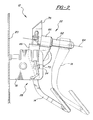
- FIG. 2 is a side view of the subject pedal assembly showing a pedal arm in fore and aft positions;
- FIG. 3 is a side view of the subject pedal assembly in a pivoted position
- FIG. 4 is an exploded view of the pedal assembly shown in FIG. 3;
- FIG. 5 is a front view, partially in cross-section , of the pedal assembly shown in FIG. 3 .
- FIG. 1 a vehicle 10 with a control pedal apparatus 12 is shown in FIG. 1 .
- the control pedal apparatus 12 includes a pedal arm 14 that can be adjusted in fore and aft directions with respect to the vehicle 10 by a driver 16 . This adjustment capability allows the pedal arm 14 to be positioned to accommodate drivers 16 of various heights.
- the vehicle control pedal apparatus 12 includes a support 18 adapted to be mounted to a vehicle structure 20 such as a firewall or dash member, for example.
- the support 18 can be a bracket, housing, or other structural support member known in the art.
- the support 18 can be a unitary member that is attached directly to the vehicle structure 20 or the support 18 can be comprised of a plurality of support members, one of which is attached to the vehicle structure 20 .
- the control pedal apparatus 12 further includes an adjustable pedal assembly 22 with a pedal arm 14 that is moveable in fore and aft directions with respect to the support 18 .
- the pedal arm 14 is shown in the furthest adjustment position in the fore direction in solid lines and in the furthest adjustment position in the aft direction in dashed lines.
- the adjustable pedal assembly 22 preferably includes an electric motor (not shown) for controlling the movement of the pedal arm 14 in the fore and aft directions, as is well known in the art.
- the adjustable pedal assembly 22 can be any of various adjustable pedal assemblies known in the art.
- the adjustable pedal assembly 22 could be similar to the adjustable pedal assembly in U.S. Pat. No. 5,632,183 assigned to the assignee of the present invention and incorporated herein by reference.
- a pivot 24 pivotally supports the adjustable pedal assembly 22 with respect to the vehicle structure 20 and defines a pivot axis 26 (shown in FIG. 5 ).
- the pivot 24 is preferably comprised of a first pivot member 34 defining a first pivot member axis 36 and a second pivot member 38 defining a second pivot member axis 40 .
- the first 36 and second 40 pivot member axes are collinear to define the pivot axis 26 . While two pivot members 34 , 38 are preferred a single pivot could be used or additional pivot members could be used to provide additional pivotal support.
- the first 34 and second 38 pivot members are longitudinally spaced apart from one another to define a clearance space 42 for the pedal arm 14 as the pedal arm 14 pivots about the pivot axis 26 .
- the pedal arm 14 can move between the first 34 and second 38 pivot members without coming into contact with the pivot members 34 , 38 . If only a single pivot member is used, the clearance space 42 between pivot members is not needed.
- the control pedal apparatus 12 also includes an electronic throttle control mechanism 28 attached to the vehicle structure 20 for controlling an engine throttle 30 shown schematically in FIG. 1 .
- the electronic throttle control 28 is responsive to the pivot 24 and provides a signal 32 that corresponds to pedal arm position as the pedal arm 14 pivots about the pivot axis 26 between rest and applied positions. Thus, the signal 32 will vary as the pedal arm 14 moves from the rest position to the applied position.
- the electronic throttle control mechanism 28 can be any of various electronic throttle control mechanisms known in the art, as the one described in U.S. Pat. No. 5,819,593 assigned to the assignee of the present invention and incorporated herein by reference.
- the electronic throttle control 28 is preferably responsive to the first pivot member 34 to provide the signal 32 that corresponds to pedal arm position.
- the second pivot member 38 preferably provides pivotal balance for the pedal arm 14 as the pedal arm 14 pivots about the pivot axis 26 . It should be understood however that the electronic throttle control 28 could also be mounted on the opposite side of the control pedal assembly 12 such that the second pivot member 38 provides input to product the signal 32 while the first pivot member 34 provides additional balance for the pedal arm 14 as it pivots.
- the electronic throttle control mechanism 28 preferably includes a first housing portion 42 and a second housing portion 44 , shown in FIG. 4 .
- the housing portions 42 , 44 partially serve as the support 18 for the control pedal apparatus 12 and are fixed relative to the vehicle structure 20 .
- the adjustable pedal assembly 22 is supported on a bracket 46 that is mounted to the housing portions 42 , 44 .
- the second housing portion 44 includes a first pivotal support 54 and a second pivotal support 56 .
- the first pivotal support 54 receives the first pivot member 34 and the second pivotal support 56 receives the second pivot member 38 .
- the first 34 and second 38 pivot members form the pivot 24 about which the pedal arm 14 pivots.
- the bracket 46 includes a first leg 48 and a second leg 50 that extend downwardly from a central base member 52 . While the bracket 46 is shown with two legs 48 , 50 , the bracket 46 could also be configured to have only a single leg or could have additional leg members. The bracket 46 need only provide partial support for the adjustable pedal assembly 22 .
- the bracket 46 is partially installed within the second housing member 44 such that the first pivotal support 54 is adjacent to the first leg 48 and the second pivotal support 56 is adjacent to the second leg 50 .
- the first housing portion 42 is attached to the second housing portion near the first pivotal support 54 to enclose the electronic throttle control 28 .
- the first housing portion 42 preferably includes tab receivers 58 for snap fit attachment to tabs 60 located on the second housing portion 44 .
- the bracket 46 pivots about the pivot axis 26 when a force is applied to the pedal arm 14 to move the pedal arm 14 from the rest to the applied position.
- the electronic throttle control 28 is fixed with respect to the vehicle structure 20 such that the pedal arm 14 moves in fore and aft directions with respect to the electronic throttle control 28 and with respect to the vehicle structure 20 .
- the adjustable pedal assembly 22 pivots with respect to the vehicle structure 20 and moves the pedal arm 14 in fore and aft directions with respect to the vehicle structure 20 , while the electronic throttle control 28 remains fixed with respect to the vehicle structure 20 .
- the pedal arm 14 moves independently from the electronic throttle control 28 .
- the pedal arm 14 moves in fore and aft directions with respect to the pivot 24 .
- the adjustable pedal assembly 22 includes a guide rod 62 for supporting the pedal arm 14 and which defines a longitudinal axis 64 .
- the pedal arm 14 moves in the fore and aft directions along the longitudinal axis 64 .
- the longitudinal axis 64 is perpendicular to the pivot axis 26 .
- the guide rod 62 is rotatable about the pivot axis 26 along with the bracket 46 when the pedal arm 14 pivots about the pivot axis 26 .
- the adjustable pedal assembly 22 further includes a bearing member 66 for slidably supporting the pedal arm 14 on the guide rod 62 .
- the bearing member 66 is preferably a bushing, however, other bearing members well known in the art can be used.
- an electric motor is used to drive a screw drive mechanism housed within the guide rod 62 , which causes the bearing member 66 and the pedal arm 14 to move along the guide rod 62 .
- the control pedal apparatus 12 also includes a resilient member 68 , shown in FIG. 5, which reacts between the pedal arm 14 and the bracket 46 for providing resistance as the pedal arm 14 is moved from the rest position to the applied position.
- This resistance provides a “feel” 16 as the pedal arm 14 pivots that corresponds to the feel that a driver experiences in pedal assembly having a cable assembly as part of a mechanical link to the engine throttle 30 .
- the resilient member 68 is preferably a coil spring with a spring center 70 that is concentric with the pivot 24 .
- the spring 68 has a first spring end 72 engaging the pedal arm 14 and a second spring end 74 engaging the bracket 46 . In addition to providing resistance as the pedal arm 14 is moved to the applied position, the spring 68 returns the pedal arm 14 to the rest position after a force applied to the pedal arm 14 has been removed.
- the spring 68 is supported by a cylindrical portion 76 that extends inwardly from the second housing portion 44 of the electronic throttle control 28 , toward the pedal arm 14 .
- the cylindrical portion 76 is located between the pedal arm 14 and the first leg 48 of the bracket 46 .
- the spring 68 is shown as a coil spring that is supported about pivot 24 , other spring configurations known in the art could also be used. Also, the spring 68 could be located at a position other than about pivot 24 . The main function of the spring 68 is to act upon the pedal arm 14 to provide a feel to the driver as the pedal arm 14 pivots.
- a cable attachment member 78 can optionally be supported on one of the pivot members 34 , 38 to support a cable assembly for attachment to the engine throttle 30 .
- This configuration would be used in place of the electronic throttle control 28 ; i.e., the configuration is used with a pedal assembly having a mechanical link to the throttle.
- the control pedal apparatus 12 of the subject invention provides both an adjustment apparatus 22 and an electronic throttle control 28 in an assembly that requires less packaging space and which requires fewer components than prior art control pedals. This reduces overall assembly time and reduces material costs.
- the control pedal apparatus 12 provides the additional benefits of having a single pivot ( 24 ) to pivotally support the pedal arm 14 in addition to providing input to the electronic throttle control 28 .
- the control pedal apparatus 12 allows adjustment of the pedal arm 14 in fore and aft directions without having to move the electronic throttle control unit 28 along with the pedal arm 14 , and the electronic throttle control 28 is responsive to the pivot 24 about which the adjustable pedal assembly 22 rotates.
Landscapes
- Physics & Mathematics (AREA)
- General Physics & Mathematics (AREA)
- Engineering & Computer Science (AREA)
- Automation & Control Theory (AREA)
- Auxiliary Drives, Propulsion Controls, And Safety Devices (AREA)
- Control Of Throttle Valves Provided In The Intake System Or In The Exhaust System (AREA)
- Mechanical Control Devices (AREA)
Abstract
Description
Claims (4)
Priority Applications (1)
| Application Number | Priority Date | Filing Date | Title |
|---|---|---|---|
| US09/643,422 US6237565B1 (en) | 1999-01-26 | 2000-08-22 | Adjustable pedal assembly with electronic throttle control |
Applications Claiming Priority (2)
| Application Number | Priority Date | Filing Date | Title |
|---|---|---|---|
| US09/236,975 US6109241A (en) | 1999-01-26 | 1999-01-26 | Adjustable pedal assembly with electronic throttle control |
| US09/643,422 US6237565B1 (en) | 1999-01-26 | 2000-08-22 | Adjustable pedal assembly with electronic throttle control |
Related Parent Applications (1)
| Application Number | Title | Priority Date | Filing Date |
|---|---|---|---|
| US09/236,975 Continuation US6109241A (en) | 1999-01-26 | 1999-01-26 | Adjustable pedal assembly with electronic throttle control |
Publications (1)
| Publication Number | Publication Date |
|---|---|
| US6237565B1 true US6237565B1 (en) | 2001-05-29 |
Family
ID=22891801
Family Applications (2)
| Application Number | Title | Priority Date | Filing Date |
|---|---|---|---|
| US09/236,975 Expired - Fee Related US6109241A (en) | 1999-01-26 | 1999-01-26 | Adjustable pedal assembly with electronic throttle control |
| US09/643,422 Expired - Fee Related US6237565B1 (en) | 1999-01-26 | 2000-08-22 | Adjustable pedal assembly with electronic throttle control |
Family Applications Before (1)
| Application Number | Title | Priority Date | Filing Date |
|---|---|---|---|
| US09/236,975 Expired - Fee Related US6109241A (en) | 1999-01-26 | 1999-01-26 | Adjustable pedal assembly with electronic throttle control |
Country Status (4)
| Country | Link |
|---|---|
| US (2) | US6109241A (en) |
| EP (1) | EP1024421A3 (en) |
| JP (1) | JP3450245B2 (en) |
| CA (1) | CA2291903C (en) |
Cited By (19)
| Publication number | Priority date | Publication date | Assignee | Title |
|---|---|---|---|---|
| US6316897B1 (en) * | 2000-07-18 | 2001-11-13 | Ford Global Tech., Inc. | System for controlling adjustable pedals |
| WO2003023543A1 (en) * | 2000-07-12 | 2003-03-20 | Ksr Industrial Corporation | Adjustable control vehicle pedal |
| US6536300B1 (en) | 2001-07-18 | 2003-03-25 | Brunswick Corporation | Adjustable foot pedal apparatus |
| US6564672B2 (en) | 2000-05-15 | 2003-05-20 | Grand Haven Stamped Products, Division Of Jsj Corporation | Adjustable pedal apparatus |
| US6619155B2 (en) | 2000-05-15 | 2003-09-16 | Grand Haven Stamped Products, Division Of Jsj Corporation | Adjustable pedal apparatus |
| US6918316B2 (en) | 1997-11-21 | 2005-07-19 | Technology Holding Company | Adjustable pedal assembly |
| US6962094B2 (en) | 2001-01-24 | 2005-11-08 | Orscheln Products Llc | Adjustable pedal assembly |
| US20050268741A1 (en) * | 2002-10-02 | 2005-12-08 | Klaus Wilczek | Floor pedal with a rotation angle sensor |
| US20060086201A1 (en) * | 2004-10-21 | 2006-04-27 | Weldon Craig A | Actuator apparatus incorporating a controller |
| US20060086200A1 (en) * | 2004-10-21 | 2006-04-27 | Weldon Craig A | System for adjusting the pedals of a vehicle |
| US20080173122A1 (en) * | 2007-01-17 | 2008-07-24 | Polaris Industries Inc. | Adjustable foot control for vehicle |
| US7778456B2 (en) | 1995-05-02 | 2010-08-17 | Cummins-Allison, Corp. | Automatic currency processing system having ticket redemption module |
| US7929749B1 (en) | 2006-09-25 | 2011-04-19 | Cummins-Allison Corp. | System and method for saving statistical data of currency bills in a currency processing device |
| US7946406B2 (en) | 2005-11-12 | 2011-05-24 | Cummins-Allison Corp. | Coin processing device having a moveable coin receptacle station |
| US7980378B2 (en) | 2006-03-23 | 2011-07-19 | Cummins-Allison Corporation | Systems, apparatus, and methods for currency processing control and redemption |
| US8069750B2 (en) | 2007-08-09 | 2011-12-06 | Ksr Technologies Co. | Compact pedal assembly with improved noise control |
| USRE44252E1 (en) | 2002-01-10 | 2013-06-04 | Cummins-Allison Corp. | Coin redemption system |
| US8950566B2 (en) | 1996-05-13 | 2015-02-10 | Cummins Allison Corp. | Apparatus, system and method for coin exchange |
| US11407432B2 (en) | 2020-04-30 | 2022-08-09 | Toyota Motor Engineering & Manufacturing North America, Inc. | Connectivity-enabled traffic-aware supplemental sensor control for informed driving |
Families Citing this family (13)
| Publication number | Priority date | Publication date | Assignee | Title |
|---|---|---|---|---|
| US6209418B1 (en) * | 1999-08-26 | 2001-04-03 | Teleflex Incorporated | Mechanical kickdown for electronic throttle control pedal assembly |
| AU1353101A (en) * | 1999-10-29 | 2001-05-14 | William C. Staker | Electronic throttle control pedal, position sensing device and assembly method |
| US6857336B2 (en) * | 1999-11-23 | 2005-02-22 | William C. Staker | Electronic pedal assembly and method for providing a tuneable hystersis force |
| US6523433B1 (en) * | 1999-11-23 | 2003-02-25 | William C. Staker | Electronic pedal assembly and method for providing a tuneable hysteresis force |
| US6739212B2 (en) | 2000-12-22 | 2004-05-25 | Dura Global Technologies, Inc. | Adjustable pedal controller with obstruction detection |
| US6516683B2 (en) | 2000-12-29 | 2003-02-11 | Dura Global Technologies, Inc. | Electric adjustable pedal system with mechanical active lock-up |
| US6581491B2 (en) | 2001-02-13 | 2003-06-24 | Grand Haven Stamped Products, Division Of Jsj Corporation | Pedal with tongued connection for improved torsional strength |
| US6655231B2 (en) | 2001-02-21 | 2003-12-02 | Ksr Industrial Corporation | Pedal adjuster for electronic throttle control |
| US7114411B2 (en) * | 2001-05-09 | 2006-10-03 | Ksr Industrial Corporation | Pedal adjuster |
| US6862950B2 (en) | 2001-11-02 | 2005-03-08 | Ksr Industrial Corporation | Adjustable pedal assembly |
| US7793566B2 (en) * | 2005-10-31 | 2010-09-14 | Grand Haven Stamped Products Company, Division Of Jsj Corporation | Pedal with hysteresis mechanism |
| CN102001286B (en) * | 2010-11-23 | 2012-12-19 | 上海神舟汽车设计开发有限公司 | Electromagnetic chuck moped pedal of automobile clutch |
| CN115179757B (en) * | 2022-09-03 | 2023-03-10 | 秦皇岛零叁邀柒科技开发有限公司 | Electronic accelerator with automatic switching and oil-saving functions and control method |
Citations (2)
| Publication number | Priority date | Publication date | Assignee | Title |
|---|---|---|---|---|
| US4470570A (en) | 1982-09-29 | 1984-09-11 | The Boeing Company | Control assembly for aircraft |
| US5056742A (en) | 1987-11-13 | 1991-10-15 | The Boeing Company | Modular rudder pedal and brake control assembly for aircraft |
Family Cites Families (17)
| Publication number | Priority date | Publication date | Assignee | Title |
|---|---|---|---|---|
| US4528590A (en) * | 1983-11-09 | 1985-07-09 | Allied Corporation | Electronic treadle |
| JPS6473134A (en) * | 1987-09-14 | 1989-03-17 | Mazda Motor | Throttle valve opening control device for vehicle |
| US4883037A (en) * | 1988-02-17 | 1989-11-28 | Automotive Products Plc | Throttle control system |
| DE3825075C1 (en) * | 1988-07-23 | 1989-09-28 | Daimler-Benz Aktiengesellschaft, 7000 Stuttgart, De | |
| JP2881776B2 (en) * | 1988-08-31 | 1999-04-12 | アイシン精機株式会社 | Throttle control device |
| US4915075A (en) * | 1989-03-20 | 1990-04-10 | Caterpillar Inc. | Accelerator pedal position sensor |
| US4958607A (en) * | 1989-04-18 | 1990-09-25 | Williams Controls, Inc. | Foot pedal arrangement for electronic throttle control of truck engines |
| US5063811A (en) * | 1990-07-09 | 1991-11-12 | Ford Motor Company | Accelerator pedal assembly |
| US5233882A (en) * | 1990-07-12 | 1993-08-10 | General Motors Corporation | Remote control lever module |
| JPH0550871A (en) * | 1991-08-21 | 1993-03-02 | Hitachi Ltd | Electric slot actuator |
| US5241936A (en) * | 1991-09-09 | 1993-09-07 | Williams Controls, Inc. | Foot pedal arrangement for electronic throttle control of truck engines |
| US5416295A (en) * | 1992-12-18 | 1995-05-16 | Cts Corporation | Combined pedal force switch and position sensor |
| US5385068A (en) * | 1992-12-18 | 1995-01-31 | Cts Corporation | Electronic accelerator pedal assembly with pedal force sensor |
| US5460061A (en) * | 1993-09-17 | 1995-10-24 | Comfort Pedals, Inc. | Adjustable control pedal apparatus |
| US5819593A (en) * | 1995-08-09 | 1998-10-13 | Comcorp Technologies, Inc. | Electronic adjustable pedal assembly |
| US5632183A (en) * | 1995-08-09 | 1997-05-27 | Comfort Pedals, Inc. | Adjustable pedal assembly |
| US5887488A (en) * | 1997-04-16 | 1999-03-30 | Imo Industries, Inc. | Vehicular accelerator pedal apparatus |
-
1999
- 1999-01-26 US US09/236,975 patent/US6109241A/en not_active Expired - Fee Related
- 1999-11-24 EP EP99203940A patent/EP1024421A3/en not_active Withdrawn
- 1999-12-07 CA CA002291903A patent/CA2291903C/en not_active Expired - Fee Related
- 1999-12-09 JP JP34991199A patent/JP3450245B2/en not_active Expired - Fee Related
-
2000
- 2000-08-22 US US09/643,422 patent/US6237565B1/en not_active Expired - Fee Related
Patent Citations (2)
| Publication number | Priority date | Publication date | Assignee | Title |
|---|---|---|---|---|
| US4470570A (en) | 1982-09-29 | 1984-09-11 | The Boeing Company | Control assembly for aircraft |
| US5056742A (en) | 1987-11-13 | 1991-10-15 | The Boeing Company | Modular rudder pedal and brake control assembly for aircraft |
Cited By (29)
| Publication number | Priority date | Publication date | Assignee | Title |
|---|---|---|---|---|
| US7778456B2 (en) | 1995-05-02 | 2010-08-17 | Cummins-Allison, Corp. | Automatic currency processing system having ticket redemption module |
| US8950566B2 (en) | 1996-05-13 | 2015-02-10 | Cummins Allison Corp. | Apparatus, system and method for coin exchange |
| US6918316B2 (en) | 1997-11-21 | 2005-07-19 | Technology Holding Company | Adjustable pedal assembly |
| US6564672B2 (en) | 2000-05-15 | 2003-05-20 | Grand Haven Stamped Products, Division Of Jsj Corporation | Adjustable pedal apparatus |
| US6619155B2 (en) | 2000-05-15 | 2003-09-16 | Grand Haven Stamped Products, Division Of Jsj Corporation | Adjustable pedal apparatus |
| US20040003675A1 (en) * | 2000-05-15 | 2004-01-08 | Brock Robert D. | Adjustable pedal apparatus |
| US6925905B2 (en) | 2000-05-15 | 2005-08-09 | Grand Haven Stamped Products, Divison Of Jsj Corporation | Adjustable pedal apparatus |
| US20040217726A1 (en) * | 2000-07-12 | 2004-11-04 | Willemsen Larry G. | Adjustable control vehicle pedal |
| WO2003023543A1 (en) * | 2000-07-12 | 2003-03-20 | Ksr Industrial Corporation | Adjustable control vehicle pedal |
| US7353729B2 (en) | 2000-07-12 | 2008-04-08 | Ksr Technologies Co. | Adjustable control vehicle pedal |
| US6316897B1 (en) * | 2000-07-18 | 2001-11-13 | Ford Global Tech., Inc. | System for controlling adjustable pedals |
| US6962094B2 (en) | 2001-01-24 | 2005-11-08 | Orscheln Products Llc | Adjustable pedal assembly |
| US6536300B1 (en) | 2001-07-18 | 2003-03-25 | Brunswick Corporation | Adjustable foot pedal apparatus |
| AU2001293238B2 (en) * | 2001-08-31 | 2007-12-13 | Ksr Technologies Co. | Adjustable control vehicle pedal |
| KR100815973B1 (en) * | 2001-08-31 | 2008-03-21 | 케이에스알 테크놀로지즈 컴퍼니 | Car adjustable control pedal |
| USRE44252E1 (en) | 2002-01-10 | 2013-06-04 | Cummins-Allison Corp. | Coin redemption system |
| US7212914B2 (en) * | 2002-10-02 | 2007-05-01 | Ab Elektronik Gmbh | Floor pedal with a rotation angle sensor |
| US20050268741A1 (en) * | 2002-10-02 | 2005-12-08 | Klaus Wilczek | Floor pedal with a rotation angle sensor |
| US20060086200A1 (en) * | 2004-10-21 | 2006-04-27 | Weldon Craig A | System for adjusting the pedals of a vehicle |
| US7640826B2 (en) | 2004-10-21 | 2010-01-05 | Continental Automotive Canada, Inc. | Actuator apparatus incorporating a controller |
| US7681474B2 (en) | 2004-10-21 | 2010-03-23 | Continental Automotive Systems Us, Inc. | System for adjusting the pedals of a vehicle |
| US20060086201A1 (en) * | 2004-10-21 | 2006-04-27 | Weldon Craig A | Actuator apparatus incorporating a controller |
| US7946406B2 (en) | 2005-11-12 | 2011-05-24 | Cummins-Allison Corp. | Coin processing device having a moveable coin receptacle station |
| US7980378B2 (en) | 2006-03-23 | 2011-07-19 | Cummins-Allison Corporation | Systems, apparatus, and methods for currency processing control and redemption |
| US7929749B1 (en) | 2006-09-25 | 2011-04-19 | Cummins-Allison Corp. | System and method for saving statistical data of currency bills in a currency processing device |
| US7832516B2 (en) | 2007-01-17 | 2010-11-16 | Polaris Industries Inc. | Adjustable foot control for vehicle |
| US20080173122A1 (en) * | 2007-01-17 | 2008-07-24 | Polaris Industries Inc. | Adjustable foot control for vehicle |
| US8069750B2 (en) | 2007-08-09 | 2011-12-06 | Ksr Technologies Co. | Compact pedal assembly with improved noise control |
| US11407432B2 (en) | 2020-04-30 | 2022-08-09 | Toyota Motor Engineering & Manufacturing North America, Inc. | Connectivity-enabled traffic-aware supplemental sensor control for informed driving |
Also Published As
| Publication number | Publication date |
|---|---|
| CA2291903C (en) | 2006-07-11 |
| US6109241A (en) | 2000-08-29 |
| JP3450245B2 (en) | 2003-09-22 |
| CA2291903A1 (en) | 2000-07-26 |
| JP2000213379A (en) | 2000-08-02 |
| EP1024421A3 (en) | 2002-03-20 |
| EP1024421A2 (en) | 2000-08-02 |
Similar Documents
| Publication | Publication Date | Title |
|---|---|---|
| US6237565B1 (en) | Adjustable pedal assembly with electronic throttle control | |
| US3643524A (en) | Control pedals for vehicles | |
| US6758115B2 (en) | Adjustable brake, clutch and accelerator pedals | |
| KR0161705B1 (en) | Pedal Arm Adjustment and Adjustment Method | |
| US6584871B2 (en) | Adjustable pedal assembly | |
| US6367348B1 (en) | Adjustable brake, clutch and accelerator pedals | |
| US3643525A (en) | Adjustable control pedals for vehicles | |
| US6516683B2 (en) | Electric adjustable pedal system with mechanical active lock-up | |
| US6186025B1 (en) | Break away pedal | |
| US6360631B1 (en) | Electronic throttle control accelerator pedal mechanism with mechanical hysteresis provider | |
| US6173625B1 (en) | Adjustable multi-pedal assembly | |
| US20020073800A1 (en) | Adjustable automobile pedal system | |
| KR100395738B1 (en) | Adjustable pedal-parallel screw and rod | |
| US6389927B1 (en) | Adjustable control vehicle pedal | |
| US6443028B1 (en) | Adjustable control pedal assembly for motor vehicle | |
| US6609438B1 (en) | Electric adjustable pedal system with two-piece upper arm | |
| US6925904B2 (en) | Adjustable pedal mechanism with tapered rivet for automatic gap and wear protection | |
| US6209417B1 (en) | Adjustable pedal with constant ratio cable assembly | |
| US7353729B2 (en) | Adjustable control vehicle pedal | |
| MXPA00000724A (en) | Adjustable pedal assembly with electronic throttle control | |
| US7832305B2 (en) | Adjustable pedal system with low brake ratio change | |
| AU2001293238A1 (en) | Adjustable control vehicle pedal | |
| US6598495B2 (en) | Plastic adjustable accelerator pedal with internal drive mechanism |
Legal Events
| Date | Code | Title | Description |
|---|---|---|---|
| CC | Certificate of correction | ||
| FPAY | Fee payment |
Year of fee payment: 4 |
|
| AS | Assignment |
Owner name: WELLS FARGO FOOTHILL, INC., AS AGENT, GEORGIA Free format text: SECURITY AGREEMENT;ASSIGNOR:DRIVESOL WORLDWIDE, INC.;REEL/FRAME:016769/0421 Effective date: 20051108 |
|
| AS | Assignment |
Owner name: DRIVESOL WORLDWIDE, INC., MICHIGAN Free format text: ASSIGNMENT OF ASSIGNORS INTEREST;ASSIGNORS:TELEFLEX INCORPORATED;TELEFLEX HOLDING COMPANY;TELEFLEX HOLDING COMPANY II;AND OTHERS;REEL/FRAME:017262/0061 Effective date: 20050812 |
|
| AS | Assignment |
Owner name: SUN DRIVESOL FINANCE, LLC, FLORIDA Free format text: SECURITY AGREEMENT;ASSIGNORS:DRIVESOL INTERMEDIATE HOLDING CORP.;DRIVESOL WORLDWIDE, INC.;DRIVESOL AUTOMOTIVE INCORPORATED;AND OTHERS;REEL/FRAME:021158/0208 Effective date: 20080625 |
|
| AS | Assignment |
Owner name: SUN DRIVESOL FINANCE, LLC, FLORIDA Free format text: AMENDED AND RESTATED PATENT SECURITY AGREEMENT;ASSIGNORS:DRIVESOL INTERMEDIATE HOLDING CORP.;DRIVESOL WORLDWIDE, INC.;DRIVESOL AUTOMOTIVE INCORPORATED;AND OTHERS;REEL/FRAME:021561/0335 Effective date: 20080919 |
|
| REMI | Maintenance fee reminder mailed | ||
| AS | Assignment |
Owner name: DRIVESOL WORLDWIDE, INC., MICHIGAN Free format text: RELEASE BY SECURED PARTY;ASSIGNOR:WELLS FARGO FOOTHILL, INC., AS AGENT;REEL/FRAME:022542/0868 Effective date: 20090409 |
|
| LAPS | Lapse for failure to pay maintenance fees | ||
| STCH | Information on status: patent discontinuation |
Free format text: PATENT EXPIRED DUE TO NONPAYMENT OF MAINTENANCE FEES UNDER 37 CFR 1.362 |
|
| FP | Lapsed due to failure to pay maintenance fee |
Effective date: 20090529 |