US6236625B1 - Optical disc system having current monitoring circuit with controller for laser driver and method for operating same - Google Patents
Optical disc system having current monitoring circuit with controller for laser driver and method for operating same Download PDFInfo
- Publication number
- US6236625B1 US6236625B1 US08/999,892 US99989297A US6236625B1 US 6236625 B1 US6236625 B1 US 6236625B1 US 99989297 A US99989297 A US 99989297A US 6236625 B1 US6236625 B1 US 6236625B1
- Authority
- US
- United States
- Prior art keywords
- monitoring circuit
- disc
- bias coil
- output
- current monitoring
- Prior art date
- Legal status (The legal status is an assumption and is not a legal conclusion. Google has not performed a legal analysis and makes no representation as to the accuracy of the status listed.)
- Expired - Fee Related
Links
Images


Classifications
-
- G—PHYSICS
- G11—INFORMATION STORAGE
- G11B—INFORMATION STORAGE BASED ON RELATIVE MOVEMENT BETWEEN RECORD CARRIER AND TRANSDUCER
- G11B11/00—Recording on or reproducing from the same record carrier wherein for these two operations the methods are covered by different main groups of groups G11B3/00 - G11B7/00 or by different subgroups of group G11B9/00; Record carriers therefor
- G11B11/10—Recording on or reproducing from the same record carrier wherein for these two operations the methods are covered by different main groups of groups G11B3/00 - G11B7/00 or by different subgroups of group G11B9/00; Record carriers therefor using recording by magnetic means or other means for magnetisation or demagnetisation of a record carrier, e.g. light induced spin magnetisation; Demagnetisation by thermal or stress means in the presence or not of an orienting magnetic field
- G11B11/105—Recording on or reproducing from the same record carrier wherein for these two operations the methods are covered by different main groups of groups G11B3/00 - G11B7/00 or by different subgroups of group G11B9/00; Record carriers therefor using recording by magnetic means or other means for magnetisation or demagnetisation of a record carrier, e.g. light induced spin magnetisation; Demagnetisation by thermal or stress means in the presence or not of an orienting magnetic field using a beam of light or a magnetic field for recording by change of magnetisation and a beam of light for reproducing, i.e. magneto-optical, e.g. light-induced thermomagnetic recording, spin magnetisation recording, Kerr or Faraday effect reproducing
- G11B11/1055—Disposition or mounting of transducers relative to record carriers
- G11B11/10576—Disposition or mounting of transducers relative to record carriers with provision for moving the transducers for maintaining alignment or spacing relative to the carrier
-
- G—PHYSICS
- G11—INFORMATION STORAGE
- G11B—INFORMATION STORAGE BASED ON RELATIVE MOVEMENT BETWEEN RECORD CARRIER AND TRANSDUCER
- G11B11/00—Recording on or reproducing from the same record carrier wherein for these two operations the methods are covered by different main groups of groups G11B3/00 - G11B7/00 or by different subgroups of group G11B9/00; Record carriers therefor
- G11B11/10—Recording on or reproducing from the same record carrier wherein for these two operations the methods are covered by different main groups of groups G11B3/00 - G11B7/00 or by different subgroups of group G11B9/00; Record carriers therefor using recording by magnetic means or other means for magnetisation or demagnetisation of a record carrier, e.g. light induced spin magnetisation; Demagnetisation by thermal or stress means in the presence or not of an orienting magnetic field
- G11B11/105—Recording on or reproducing from the same record carrier wherein for these two operations the methods are covered by different main groups of groups G11B3/00 - G11B7/00 or by different subgroups of group G11B9/00; Record carriers therefor using recording by magnetic means or other means for magnetisation or demagnetisation of a record carrier, e.g. light induced spin magnetisation; Demagnetisation by thermal or stress means in the presence or not of an orienting magnetic field using a beam of light or a magnetic field for recording by change of magnetisation and a beam of light for reproducing, i.e. magneto-optical, e.g. light-induced thermomagnetic recording, spin magnetisation recording, Kerr or Faraday effect reproducing
- G11B11/10502—Recording on or reproducing from the same record carrier wherein for these two operations the methods are covered by different main groups of groups G11B3/00 - G11B7/00 or by different subgroups of group G11B9/00; Record carriers therefor using recording by magnetic means or other means for magnetisation or demagnetisation of a record carrier, e.g. light induced spin magnetisation; Demagnetisation by thermal or stress means in the presence or not of an orienting magnetic field using a beam of light or a magnetic field for recording by change of magnetisation and a beam of light for reproducing, i.e. magneto-optical, e.g. light-induced thermomagnetic recording, spin magnetisation recording, Kerr or Faraday effect reproducing characterised by the transducing operation to be executed
- G11B11/10504—Recording
-
- G—PHYSICS
- G11—INFORMATION STORAGE
- G11B—INFORMATION STORAGE BASED ON RELATIVE MOVEMENT BETWEEN RECORD CARRIER AND TRANSDUCER
- G11B11/00—Recording on or reproducing from the same record carrier wherein for these two operations the methods are covered by different main groups of groups G11B3/00 - G11B7/00 or by different subgroups of group G11B9/00; Record carriers therefor
- G11B11/10—Recording on or reproducing from the same record carrier wherein for these two operations the methods are covered by different main groups of groups G11B3/00 - G11B7/00 or by different subgroups of group G11B9/00; Record carriers therefor using recording by magnetic means or other means for magnetisation or demagnetisation of a record carrier, e.g. light induced spin magnetisation; Demagnetisation by thermal or stress means in the presence or not of an orienting magnetic field
- G11B11/105—Recording on or reproducing from the same record carrier wherein for these two operations the methods are covered by different main groups of groups G11B3/00 - G11B7/00 or by different subgroups of group G11B9/00; Record carriers therefor using recording by magnetic means or other means for magnetisation or demagnetisation of a record carrier, e.g. light induced spin magnetisation; Demagnetisation by thermal or stress means in the presence or not of an orienting magnetic field using a beam of light or a magnetic field for recording by change of magnetisation and a beam of light for reproducing, i.e. magneto-optical, e.g. light-induced thermomagnetic recording, spin magnetisation recording, Kerr or Faraday effect reproducing
- G11B11/10595—Control of operating function
Definitions
- This invention relates to magneto-optical data storage systems. More particularly, this invention relates to an improvement in writing information onto an magneto-optical disc by a magneto-optical disc drive in a high density format.
- optical data storage systems are becoming an increasingly popular means for meeting this expanding demand. These optical data systems provide large volumes of relatively low-cost storage that may be quickly accessed.
- coded video signals, audio signals, or other information signals are recorded on a disc in the form of information tracks on one or both planar surfaces of the disc.
- At the heart of an optical storage system is at least one laser (or other light source).
- the laser In a first operating mode, the laser generates a high-intensity laser beam that is focused on a small spot on an information track of a rotating storage disc.
- This high-intensity laser beam raises the temperature of the recording surface of the material above its Curie Point—the point at which the material loses its magnetization and accepts the magnetization of the magnetic field in which the disc is placed.
- information may be recorded on the disc in the form of magnetic domains referred to as “pits” on the recording medium.
- the laser enters a second operating mode.
- the laser generates a low-intensity laser beam that is again focused on the tracks of the rotating disc.
- This lower intensity laser beam does not heat the disc above its Curie Point.
- the laser beam is, however, reflected from the disc surface in a manner indicative of the previously recorded information due to the presence of the previously formed pits, and the previously recorded information may thereby be reproduced. Since the laser may be tightly focused, an information processing system of this type has advantages of high recording density and accurate reproduction of the recorded information.
- the components of a typical optical system include a housing with an insertion port through which the user inserts the recording media into the drive.
- This housing accommodates, among other items, the mechanical and electrical subsystems for loading, reading from, writing to, and unloading an optical disc.
- the operation of these mechanical and electrical subsystems is typically within the exclusive control of the data processing system to which the drive is connected.
- a turntable for rotating a disc thereon is typically mounted on the system baseplate.
- the turntable may comprise a spindle having a magnet upon which a disc hub is mounted for use. The magnet attracts the disc hub, thereby holding the disc in a desired position for rotation.
- optical data storage systems for storing digital information.
- standard optical disc systems may use 51 ⁇ 4 inch disks, and these optical disks may or may not be mounted in a protective case or cartridge. If the optical disc is not fixedly mounted in a protective cartridge, an operator manually removes the disc from the protective case. The operator would then manually load the disc onto a loading mechanism, using care to prevent damage to the recording surface.
- a disc may be mounted within an enclosure or a cartridge that is itself inserted into the insertion port of the drive and is then conveyed to a predetermined position.
- These disc cartridges are well known in the computer arts.
- the disc cartridge comprises a cartridge housing containing a disc upon which data may be recorded.
- the disc cartridge typically includes at least one door or shutter that is normally closed.
- the cartridge shutter may have one or more locking tabs associated with it.
- the corresponding disc drive includes a mechanism for opening the door or shutter on the cartridge as the cartridge is pushed into the system. Such a mechanism may comprise a door link that makes contact with a locking tab, thereby unlocking the shutter.
- the shutter is opened to partially expose the information recording medium contained therein. This permits a disc hub to be loaded onto a spindle of a motor or other drive mechanism, and permits entry of a read-write head and a bias magnetic into the protective cartridge.
- the disc when rotated by the drive mechanism, permits the read-write head to access all portions of the disc media.
- a conventional disc loading and unloading system that uses disc cartridges is typically capable of automatically transporting a disc cartridge from a receiving port onto the spindle. When the disc is no longer required, a conventional disc loading and unloading system automatically unloads the disc from the spindle.
- a loading device for performing this loading and unloading of the disc is generally constructed so that during disc loading (i.e., when the disc is moved from an ejected position into the player and onto the spindle), the disc is moved horizontally, parallel to the baseplate and turntable, towards the turntable. When the disc has been positioned above the turntable, the disc is lowered vertically, perpendicular to the face of the turntable, onto the spindle. Once on the turntable, a spindle magnet attracts the disc hub fixed to the center of the media, thereby clamping the disc in a rotatable condition for read-write operations.
- a cartridge “box” has four pins at its sides, and the pins ride in tracks in an adjacent sheet metal guide.
- the cartridge box lifts the disc straight up and off the spindle.
- the apparatus then moves the disc horizontally, parallel to the baseplate and turntable, towards the disc receiving port in the front of the player.
- the peak upward force required to overcome the magnetic clamping force may be produced by the mechanical operation of an ejection lever or by the activation of an electric ejection system.
- the electric ejection motor In conventional electric ejection systems, wherein the disc cartridge unloading apparatus vertically lifts the disc cartridge to break the magnetic force between the spindle magnet and the disc hub, the electric ejection motor must generate a large load to effect removal of the disc cartridge. Consequently, when an operator opts to use the electric ejection system, a large motor having a large torque is required to generate sufficient vertical lifting force. Space must be reserved in the system housing to accommodate this large motor, thereby increasing the overall size of the housing for the cartridge-loading apparatus. In addition, the large motor consumes a considerable amount of power.
- Focus and tracking corrections may be effected by moving the objective lens in either the direction of the optical axis of the lens for focusing, or in a direction perpendicular to the optical axis for tracking.
- Actuators support the objective lens and convert position correction signals from the feedback control systems into movement of the objective lens.
- these actuators comprise moving coils, stationary magnets, and a stationary yoke, wherein a magnetic field is produced in an air gap between the yoke and magnets.
- U.S. Pat. No. 4,568,142 issued to Iguma and entitled “Objective Lens Driving Apparatus” illustrates an actuator of this type wherein the actuator includes rectangular magnets positioned within U-shaped yokes. The yokes are spaced from one another with their north poles opposing, in close enough proximity to one another to form a magnetic circuit.
- a square-shaped focusing coil is bonded to the outsides of a square-shaped lens frame.
- Four tracking coils are bonded on the corners of the focusing coil.
- the ends of the focusing coil are then positioned within the air gaps formed by each of the U-shaped yokes so that the focusing coil straddles the yokes. Because the focusing coil must extend around these “center” or “inner” yoke plates, the coil cannot be wound as tightly as desired and the rigidity of the coil construction is compromised. Further, in this type of closed magnetic circuit design, the majority of coil wire is positioned outside the air gaps, significantly reducing the efficiency of the actuator.
- the stiffness of the coil in the air gap has to be very high and the coil decoupling resonance frequency should be above 10 kHz, and is most desirably above 25 kHz.
- the coil decoupling resonance frequency should be above 10 kHz, and is most desirably above 25 kHz.
- large amounts of coil wire in the magnetic air gap are often required to achieve maximum motor performance.
- the coil must be wholly or partially “freestanding”, or must be wound on the thinnest bobbin possible.
- These types of coil configurations have low stiffness and typically decouple at lower frequencies.
- the dynamic resonance behavior of many actuator designs can also cause the coil to unwind during operation.
- the decoupling frequency of the tracking coil(s) glued onto a freestanding focus coil is typically around 15 kHz, significantly below the preferred decoupling frequency.
- Optical recording and playback systems such as those utilizing optical memory disks, compact disks, or video disks, require precise focusing of an illuminating optical beam through an objective lens onto the surface of an optical disc.
- the incident illuminating beam is generally reflected back through the objective lens, and is then used to read information stored on the disc.
- a portion of the reflected beam is typically directed to an apparatus designed to gauge the focus of the illuminating beam on the disc.
- Information extracted from the reflected beam by this apparatus may then be used to adjust the focus of the illuminating beam by altering the position of a movable objective lens relative to the disc.
- U.S. Pat. Nos. 4,423,495; 4,425,636; and 4,453,239 employ what has been termed the “critical angle prism” method of determining beam focus.
- this method an illuminating beam reflected from a storage disc is made incident upon a detection prism surface which is set very close to a critical angle with respect to the reflected illuminating beam.
- the variation in the amount of optical energy reflected by the detection prism surface may be used to derive a focus error signal used to adjust the focus of the illuminating beam.
- the critical angle prism method generally requires that the orientation of the detection prism surface relative to the reflected illuminating beam be precisely adjusted. This requirement arises as a result of reflectivity characteristic of the detection prism in the neighborhood of the critical angle and makes focus error detection systems based on this method extremely sensitive.
- the critical angle technique has several disadvantages. First, the focus error signal it produces depends on the light reflection at the interface between the detection prism surface and air. Thus, changes in altitude, which change the index of refraction of the air, can cause false focus readings (offsets) to occur. Also, the critical angle technique is inherently unsuitable for use in differential focus sensing systems.
- Differential systems are increasingly important because they allow cancellation of certain types of noise that can occur in optical disc drives.
- the critical angle method is unsuited to differential operation for two reasons. First, the transmitted beam produced by the sensing prism is compressed along one axis, making it unsymmetrical with the reflected beam. Symmetry of the two beams is preferred in a differential system to optimize the noise-cancellation properties in varied environments. Second, at the point on the reflectivity curve of a critical angle prism where the intensities of the two beams are balanced, the slope is far too low to produce a useful differential focus error signal.
- a focus detecting apparatus which requires somewhat less precise adjustment of the optical surface on which the reflected illuminating beam is incident, when compared to the critical angle technique is disclosed in U.S. Pat. No. 4,862,442.
- the optical surface described therein comprises a dielectric multilayer coating having a reflectivity which varies continuously with respect to the angle of incidence of the reflected illuminating beam. It follows that rotational maladjustment of the surface comprising the multilayer coating will have smaller effect on the value of the focus error signal, but that also the technique will have reduced angular sensitivity. Also, inaccuracies in the focus error signal produced by multilayer dielectric systems may develop in response to relatively slight changes in the wavelength of the reflected illuminating beam. Such sensitivity to wavelength changes is undesirable since the focus error signal is designed to relate solely to the focus of the illuminating beam.
- FIG. 37 of U.S. Pat. No. 4,862,442 shows a particular reflectivity characteristic for a layered dielectric reflecting surface, with the slope of the reflectivity characteristic being proportional to the sensitivity of the focus error signal.
- the disclosed reflected intensity ranges in value from approximately 0.75 to 0.05 over angles of incidence extending from 42 to 48 degrees. This reflectivity change of approximately 10% per degree produces a focus error signal of relatively low sensitivity.
- optical data storage systems that utilize a focused laser beam to record and instantaneously playback information are very attractive in the computer mass storage industry.
- Such optical data storage systems offer very high data rates with very high storage density and rapid random access to the data stored on the information medium, most commonly an optical disc.
- reading and writing data is often accomplished using a single laser source functioning at two respective intensities.
- light from the laser source passes through an objective lens which converges the light beam to a specific focal point on the optical disc.
- the laser light is focused on the recording medium and is altered by the information of the data storage medium. This light is then reflected off the disc, back through the objective lens, to a photodetector.
- Focus and tracking corrections may be effected by moving the objective lens in either the direction of the optical axis of the lens for focusing, or in a direction perpendicular to the optical axis for tracking.
- the position of the objective lens in the focus and tracking directions is commonly adjusted by control systems.
- Actuators support the objective lens and convert position correction signals from the feedback control systems into movement of the objective lens.
- failure to focus the light on a small enough area of the medium will result in too large a portion of the disc being used to store a given amount of information, or in too broad an area of the disc being read.
- the failure to precisely control the tracking of the laser light will result in the information being stored in the wrong location, or in information from the wrong location being read.
- Optical disc systems often employ an anamorphic prism for adjustment of laser beam ellipticity, for the removal of laser beam astigmatism, and/or for beam steering.
- References such as U.S. Pat. No. 4,333,173 issued to Yonezawa, et al., U.S. Pat. No. 4,542,492 issued to Leterme, et al. and U.S. Pat. No. 4,607,356 issued to Bricot, et al. describe using simple anamorphic prisms for beam shaping in optical disc applications.
- the anamorphic prism systems have an embedded thin film to reflect some or all of a returning beam (reflected from optical media) to a detection system.
- U.S. Pat. No. 4,573,149 to Deguchi, et al. describes the use of thin films to reflect a return beam to detection systems.
- the entrance face of the anamorphic prism is often used to reflect the returning beam to a detection system as described in U.S. Pat. Nos. 4,542,492 and 4,607,356.
- a typical problem with conventional prisms is that the anamorphic prism suffers from chromatic dispersion which can result in lateral chromatic aberration.
- the wavelength of the light source changes, the resulting angles of refraction through the anamorphic prism also change.
- These changes result in a lateral beam shift when the beam is focused onto optical media such as an optical disc.
- optical disc systems a small shift in the beam may cause erroneous data signals. For instance, if the shift is sudden and in the data direction, the beam may skip data recorded on the optical disc.
- the chromatic aberration in the prism would not cause a problem.
- the light source e.g., a laser
- the chromatic aberration in the prism would not cause a problem.
- RF modulation is often applied to laser diodes operating at read power in order to minimize the effect that “mode-hopping” has on the system.
- the RF modulation increases the spectral bandwidth and can change the center frequency.
- RF modulation is not generally used when the laser is operating at write power.
- a sudden change in the wavelength of the incident light typically results in a lateral beam shift in the focused spot of up to several hundred nanometers. A lateral beam shift of this magnitude could cause significant errors in the data signal.
- multi-element prism systems to correct chromatic dispersion is known in the art of optical design. Textbooks such as Warren J. Smith, Modern Optical Engineering, McGraw-Hill, 1966, pp. 75-77 discuss this idea. Furthermore, some optical disc systems use multi-element anamorphic prism systems which are achromatic. Typical existing multi-element prism systems, however, require the multiple prism elements to be separately mounted. Mounting the multiple elements increases the expense and difficulty of manufacturing because each element must be carefully aligned with respect to the other elements in the system. Small deviations in alignment can cause significant variations in function. This also complicates quality control.
- Such media may include, for example, magnetic tapes or disks in systems having a variety of configurations.
- Magneto-optical (“MO”) systems exist for recording data on and retrieving data from a magnetic disc.
- the process of recording in a magneto-optical system typically involves use of a magnetic field to orient the polarity of a generalized area on the disc while a laser pulse heats a localized area, thereby fixing the polarity of the localized area.
- the localized area with fixed polarity is commonly called a pit.
- Some encoding systems use the existence or absence of a pit on the disc to define the recorded data as a “1” or “0”, respectively.
- a binary input data sequence may be converted by digital modulation to a different binary sequence having more desirable properties.
- a modulator may, for example, convert m data bits to a code word with n modulation code bits (or “binits”). In most cases, there are more code bits than data bits, that is m ⁇ n.
- the density ratio of a given recording system is often expressed according to the equation (m/n) ⁇ (d+1), where m and n have the definitions provided above, and d is defined as the minimum number of zeroes occurring between ones.
- the RLL 217/1/2 code has, according to the above equation, a density ratio of 1.5, while the GCR 0/3/8/9 code has a density ratio of 0.89.
- a focused laser beam or other optical device is typically directed at the recording surface of a rotating optical disc such that the laser beam can selectively access one of a plurality of tracks on the recorded surface.
- the rotation of the laser beam reflected from the recorded surface may be detected by means of Kerr rotation.
- a change in Kerr rotation of a first type for example, represents a first binary value.
- a change in Kerr rotation of a second type represents a second binary value.
- An output signal is generating from the first and second binary values occurring at specified clock intervals.
- Undesired DC buildup is also caused by variance in pit size due to thermal effects on the writing laser or the storage medium. As the writing laser heats up, for example, the spot size may increase leading to wider pits. When the recorded pits are read, variations in pit size will cause an unsymmetrical input signal having DC components. Variation in pit size not only causes undesired DC buildup but also causes the relative locations of the data to appear shifted in time, reducing the timing margin and leading to possible reading errors.
- Another method for handling DC buildup involves the use of double differentiation. This method typically involves detection of the peaks of a first derivative of the input signal by detecting zero-crossings of the second derivative of the input signal. Thus, the DC components are effectively filtered out.
- One drawback of this method is that differentiation or double differentiation can cause undesirable noise effects.
- a second drawback is that the method may decrease the timing margin to unacceptably low levels (e.g., by as much as 50 percent).
- the data to be stored is randomized prior to recording such that none of the data patterns repeat over a data sector.
- This method may not be acceptable by ISO standards and may lack downward compatibility with previous disc drive systems.
- de-randomizing the data may be complex.
- Yet another method for controlling DC buildup involves the use of so-called resync bytes between data segments.
- This method generally involves the examination and manipulation of data before it is recorded in order to minimize DC buildup upon readback. Before recording, two consecutive data segments are examined to determine if the patterns of 1's and 0's are such as to cause positive DC, negative DC, or no DC components when read back. If, for example, two consecutive data segments have the same DC polarity, one of the data segments is inverted prior to being recorded on the medium.
- a resync byte between the segments may need to be written so that the pattern of contiguous bits and of flux reversals is proper.
- a drawback of such a method is that it will not necessarily reduce all DC buildup, and time constants must be determined such that the predictable DC buildup will not affect performance. Further, the method requires additional overhead including the examination of data segments to determine their relative polarity.
- Magneto-optical recording is the technique commonly used to store the data on and/or retrieve the data from the disc.
- a magnetic field orients the polarity of a generalized area on the disc, while a laser pulse heats a localized area thereby fixing the polarity of the smaller area.
- the localized area with fixed polarity is commonly called a pit.
- Some encoding systems use the existence or absence of a pit on the disc to define the recorded data as a “1” or “O”, respectively.
- the most commonly used encoding system for this pit-type recording is the run length limited (RLL) 2,7 code because it gives the highest data-to-pit ratio. This type of recording, however, does not lead to higher density because amplitude and timing margins deteriorate very rapidly as frequency is increased.
- a magneto-optical disc system has a laser light source, a magnetomotive field generator that includes a bias coil for subjecting a magneto-optical storage medium to a magnetic field, and a mechanism for focusing light emitted by the light source onto the medium to effect writing thereof.
- the system includes a laser driver for energizing the laser light source.
- a bias coil driver is switchably connected to the bias coil for supplying an electric current thereto.
- a current monitoring circuit is connected to the bias coil driver, and a controller is coupled to the output of the current monitoring circuit and is connected to the laser driver. When the output of the current monitoring circuit exceeds a predetermined magnitude, the controller enables the laser driver, and information is written onto the medium when the electric current flowing in the bias coil exceeds a threshold.
- the controller includes a microprocessor.
- the microprocessor samples the output of the current monitoring circuit during an interval when the output of the current monitoring circuit is less than the predetermined magnitude, and predicts a time when the output of the current monitoring circuit exceeds a predetermined magnitude.
- the current monitoring circuit comprises a resistor divider, and an analog-to-digital convertor coupled to the divider.
- the invention provides a method for writing information onto a magneto-optical storage medium.
- a magnetomotive field generator is provided for subjecting a region of space to a magnetic field, the generator being responsive to an electric current flowing therethrough.
- the method comprises the further steps of disposing a magneto-optical storage medium in the region of space, conducting the electric current through the generator, monitoring a magnitude of the electric current, and when the magnitude exceeds a predetermined level, impinging radiant energy on the storage medium for writing information thereon.
- the generator comprises a bias coil, and the electric current flows through the coil.
- monitoring is performed by sampling during a ramp-up of the current, and predicting a time at which the predetermined level will be exceeded.
- predicting a time is performed by linear extrapolation. Predicting this time is preferably performed by referencing memorized calibration data.
- the invention provides an optical disc system for writing information onto a storage medium, the system being of the type having a focusing mechanism and a tracking mechanism, wherein the mechanisms are controlled by a feedback loop.
- the system includes an electronic circuit for generating a servo error signal, a laser light source, a laser driver for energizing the laser light source, and a magnetomotive field generator for subjecting the medium to a magnetic field, a bias coil disposed in the magnetomotive field generator.
- a bias coil driver is switchably connected to the bias coil for supplying an electric current thereto.
- a current monitoring circuit is connected to the bias coil driver.
- a controller is connected to the output of the current monitoring circuit and also connected to the laser driver, wherein the controller enables the laser driver when the output of the current monitoring circuit exceeds a predetermined magnitude. Information is thus written onto the medium at the instant when the magnetic field coil exceeds a threshold.
- FIG. 1 is an isometric view of an optical disk drive embodying the present invention
- FIG. 2 is a top view of the disk drive of FIG. 1, with the housing of the drive removed;
- FIG. 3 is a cross-sectional view of the disk drive of FIG. 1, taken in the direction of arrows 3 — 3 in FIG. 1;
- FIG. 4A is a top view of an optics module of the disk drive of FIG. 1;
- FIG. 4B is a diagram of the optical path of the disk drive of FIG. 1;
- FIG. 5 is a system block diagram of the electronics of the disk drive of FIG. 1;
- FIG. 6 is another isometric view of a disc drive with a disc cartridge about to be inserted therein;
- FIG. 7 is an exploded isometric view of the disc drive of FIG. 6, depicting the major subassemblies thereof;
- FIGS. 8A-8B are isometric views of the baseplate depicted in FIG. 7;
- FIG. 9 is a top elevational view of the drive of FIG. 6 with some features removed to better show the tiller, the tiller-driving gears, the motor that drives these gears, and the operative relationship between these features;
- FIGS. 10A-10F are elevational and isometric views of a tiller
- FIGS. 11A-11C comprise elevational and isometric views of a left slider
- FIGS. 12A-12E are elevational and isometric views of a right slider
- FIG. 13 is a top plan view of the parking arm in two positions, one drawn in phantom, showing its action of parking the carriage at the back of the drive while the drive is at rest;
- FIG. 13A is a perspective view of the disk drive of FIG. 1, illustrating in particular the fine actuator assembly carriage which supports the optics used to focus the laser beam on the data track of the optical disk;
- FIGS. 14A-14C comprise elevational and isometric views of a parking arm
- FIGS. 15A and 15B are isometric views of a cartridge receiver
- FIGS. 16A and 16B are elevational views, during insertion of a disc cartridge, of the drive of FIG. 6 with some features removed to better show the trip lug on the right door link, the latch, and the operative relationship between these features;
- FIGS. 17A and 17B are isometric views of a latch that holds the cartridge receiver in the up position
- FIG. 18 is an isometric view of a bias coil assembly clamp
- FIG. 19 is an isometric view of a bias coil assembly
- FIG. 20 is an exploded isometric view of the major components comprising the bias coil assembly
- FIG. 21 is an isometric view of a pivot bar or rail that rotatably supports the bias coil assembly
- FIG. 22 is an isometric view of the bias coil assembly flexure to which the bias coil assembly is mounted and which is, in turn, mounted to the pivot bar depicted in FIG. 21;
- FIG. 23 is an elevational view of the right side of the cartridge receiver and the cartridge just before initiation of an cartridge-eject cycle, depicting the disc mounted in operating position on the spindle;
- FIG. 24 is an elevational view of the right side of the cartridge receiver and the cartridge during the cartridge-eject cycle, depicting the cartridge being tipped and the disc being peeled off the spindle;
- FIG. 25 is an elevational view of the right side of the cartridge receiver and the cartridge during the cartridge-eject cycle, depicting the cartridge loading system in the up position and the disc starting to be ejected from the disc drive;
- FIG. 26 is a schematic perspective view of an actuator in accordance with the present invention.
- FIG. 27 is a perspective view of the lens holder for the actuator of FIG. 26;
- FIG. 28 is a perspective view of the actuator of FIG. 26 within a magnetic field housing as employed in conjunction with a recording system;
- FIG. 29 is a top plan view of the recording system of FIG. 28;
- FIG. 30 is a right side elevational view of the recording system of FIG. 28;
- FIG. 31 is a front elevational view of the recording system of FIG. 28;
- FIG. 32 is a schematic perspective view illustrating the magnetic fields produced by the magnet pairs of the actuator of FIG. 26;
- FIG. 33 is a perspective view of the focus coils and permanent magnets of the actuator of FIG. 26;
- FIG. 34 is a schematic cross-sectional view of the focus coils and permanent magnets of the actuator of FIG. 26 taken along section lines 34 — 34 of FIG. 33 illustrating the focus forces acting on the actuator;
- FIG. 35 is a schematic cross-sectional view of the tracking coil and permanent magnets of the actuator of FIG. 26 illustrating the tracking forces acting on the actuator;
- FIG. 36 is a block diagrammatic presentation of a preferred embodiment of the beam focus sensing apparatus of the present invention.
- FIG. 37 is a magnified top cross-sectional view of a differential version of the inventive beam separation module (FTR prism);
- FIG. 38 is an illustrative front view of the first and second quad detectors included within the inventive focus sensing apparatus
- FIG. 39 is a graph showing the reflectivity of the FTR prism as a function of the angle of incidence of the servo beam
- FIG. 40 is a graph of the value of a differential focus error signal generated by a preferred embodiment of the apparatus of the present invention as a function of the position of the objective lens relative to an optical disc;
- FIG. 41 schematically illustrates an exemplary optical read/write system in which the carriage and actuator assembly of the present invention may be used
- FIG. 42 is a perspective view of the carriage and actuator assembly
- FIG. 43 is an exploded view of the carriage and actuator assembly
- FIG. 44 is an exploded view of the actuator
- FIG. 45 is a schematic top view illustrating the coarse tracking forces acting on the assembly
- FIG. 46 is a side schematic view further illustrating the coarse tracking forces
- FIG. 47 is an exploded view which illustrates the focus forces acting on the actuator
- FIG. 48 is an exploded view which illustrates the fine tracking forces acting on the actuator
- FIG. 49A is a schematic top view illustrating the symmetry of coarse tracking forces in the horizontal plane
- FIG. 49B is a schematic side view illustrating the symmetry of coarse tracking forces in the vertical plane
- FIG. 50A is a schematic top view illustrating the symmetry of fine tracking forces in the horizontal plane
- FIG. 50B is a schematic end view illustrating the alignment of the net fine tracking force with the center of mass of the fine tracking motor
- FIG. 51A is a schematic top view illustrating the symmetry of fine tracking reaction forces in the horizontal plane
- FIG. 51B is a schematic end view illustrating the alignment of the net fine tracking reaction force with the center of mass of the fine tracking motor
- FIG. 52A is a schematic side view illustrating the symmetry of focus forces in the horizontal plane
- FIG. 52B is a schematic end view illustrating the alignment of the net focus force with the optical axis of the objective lens
- FIG. 53A is a schematic side view which illustrates the symmetry of focus reaction forces in the horizontal plane
- FIG. 53B is a schematic end view which illustrates the alignment of the net focus reaction force with the optical axis of the objective lens
- FIG. 54 is a schematic top view illustrating the flexure forces and fine motor reaction forces generated in response to the flexure forces
- FIG. 55A is a schematic side view which illustrates the symmetry of carriage suspension forces in the horizontal plane
- FIG. 55B is a schematic end view illustrating the alignment of the net carriage suspension force with the optical axis of the objective lens
- FIG. 56A is a schematic top view which illustrates the symmetry of friction forces in the horizontal plane
- FIG. 56B is a schematic side view illustrating the alignment of the friction forces with the center of mass of the carriage
- FIG. 57 is a schematic end view which illustrates the net inertial forces acting at the center of mass of the fine motor and center of mass of the carriage in response to a vertical acceleration;
- FIG. 58A is a schematic side view illustrating the alignment of the net inertial force of the fine motor with the optical axis of the objective lens;
- FIG. 58B is a schematic side view illustrating the alignment of the net inertial force of the carriage with the optical axis of the objective lens
- FIG. 59A is a schematic top view which illustrates the inertial forces acting on components of the carriage and actuator assembly for horizontal accelerations;
- FIG. 59B is a schematic top view illustrating the net inertial forces for horizontal accelerations
- FIG. 60A is a schematic end view which illustrates the fine motor and carriage inertial forces for accelerations above the flexure arm resonance frequency
- FIG. 60B is a schematic end view which illustrates the fine motor and carriage inertial forces for accelerations below the flexure arm resonance frequency
- FIGS. 61A-61D are diagrams illustrating the relationship between the fine tracking position versus fine motor current
- FIGS. 62A-62C illustrate the effects of asymmetrical focus forces acting on the assembly
- FIG. 63 illustrates an alternative embodiment of a carriage and actuator assembly
- FIG. 64 illustrates the operation of the actuator to move the lens holder in a focusing direction
- FIG. 65 illustrates the operation of the actuator to move the lens holder in a tracking direction
- FIG. 66 depicts a simple anamorphic prism and illustrates the effect of chromatic aberration in the prism
- FIG. 67 depicts an existing multi-element anamorphic prism system
- FIG. 68 depicts an exemplary air-spaced prism system according to the present invention.
- FIGS. 69 and 69A depict one embodiment of an air-spaced, multi-element prism system of the present invention
- FIGS. 70, 70 A, and 70 B depict side, bottom, and top plan views, respectively, of the plate prism of the prism system embodiment depicted in FIG. 69;
- FIGS. 71, 71 A, and 71 B depict side, top, and bottom plan views, respectively, of the trapezoidal prism of the embodiment of the prism system shown in FIG. 69;
- FIGS. 72 and 72A depict a side view and a plan view of one optical surface, respectively, of an embodiment of the chromatic correcting prism of the prism system embodiment shown in FIG. 69;
- FIG. 73 depicts an alternative embodiment of an air-spaced, multi-element prism system of the present invention.
- FIGS. 74, 74 A, and 74 B depict side, top and bottom plan views, respectively, of the quadrilateral prism of the alternative embodiment illustrated in FIG. 73;
- FIG. 75 is a block diagram showing an optical data storage and retrieval system
- FIGS. 76 are series of sample waveforms
- FIGS. 77A and 77B are waveform diagrams of a symmetrical and unsymmetrical input signal, respectively;
- FIG. 78 is a block diagram of a read channel
- FIG. 79A is a more detailed block diagram of various stages of a read channel
- FIG. 79B is a detailed circuit diagram of a partial integrator stage
- FIGS. 80A-80E are frequency response diagrams of various stages of a read channel
- FIG. 80F is a plot of group delay for a combination of stages in a read channel
- FIGS. 80 G(1)- 80 G(4) are waveform diagrams showing signal waveforms at various stages in the read channel
- FIG. 81 is a block diagram of a peak detection and tracking circuit
- FIG. 82 is a schematic diagram of the peak detection and tracking circuit of FIG. 81;
- FIG. 83 is a waveform diagram showing tracking by a threshold signal of the DC envelope of an input signal
- FIGS. 84A-84D are diagrams showing exemplary waveforms at various points in a read channel
- FIG. 85 is a block diagram showing the optical data storage and retrieval system
- FIGS. 86A-86B are series of waveforms showing uniform laser pulsing under a pulsed GCR format and nonuniform laser pulsing under an RLL 2,7 format;
- FIG. 87 is a series of waveforms showing laser pulsing for various data patterns adjusted by the write compensation circuit
- FIG. 88 is a schematic diagram showing the write compensation circuit
- FIG. 89 is a series of waveforms showing laser pulsing for amplitude asymmetry correction
- FIG. 90 is a schematic diagram showing the amplitude asymmetry correction circuit
- FIG. 91 is a block diagram showing the basic relationship of elements of the pulse slimming means.
- FIG. 92 is a series of waveforms showing threshold adjustments by the dynamic threshold circuit
- FIG. 93 is a schematic diagram for the dynamic threshold circuit
- FIG. 94 is a schematic block diagram of an optical data storage and retrieval system incorporating downward compatibility
- FIG. 95 is a diagram of the track layout of the high-density optical disks.
- FIG. 96 is a diagram of the sector format of the high-density optical disks.
- FIG. 97 is a block diagram in more detail showing the read/write circuitry of FIG. 94;
- FIG. 98 is a table depicting, for each of the 21 zones in the preferred format of the high-density optical disc, the tracks within the zone, the number of sectors per track within the zone, the total number of sectors in the zone, and the write frequency of the data recorded in the zone;
- FIG. 99 provides a table of the equations used to compute the CRC bits of the ID field
- FIG. 100A is the first half of a table (Hex 00 to 7F) showing how the 8-bit bytes in the three address fields and in the data field, except for the resync bytes, are converted to channel bits on the disc;
- FIG. 100B is the second half of a table (Hex 80 to FF) showing how the 8-bit bytes in the three address fields and in the data field, except for the resync bytes, are converted to channel bits on the disc;
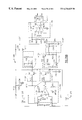
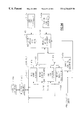
- FIGS. 101A-119C are schematic diagrams of the electronic circuitry in a preferred embodiment of the invention.
- FIG. 120 is an isometric view of a mechanical isolator and a pole piece in accordance with a first preferred embodiment
- FIG. 121 is an isometric view of the mechanical isolator in a second preferred embodiment
- FIG. 122 is a state diagram of the read mode firmware module employed in conjunction with the present invention.
- FIG. 123 is a state diagram of the write mode firmware module utilized in conjunction with this invention.
- FIG. 124 shows a Nyquist diagram of the focus loop transfer function for selected amounts of closed loop peaking
- FIG. 125 is a graphical representation of magnitude responses of the focus loop transfer function for open and closed conditions
- FIG. 126 is a graphical representation of phase responses of the focus loop transfer function for open and closed conditions
- FIG. 127 illustrates the magnitude response curves for focus compensation transfer functions
- FIG. 128 shows the phase response curves for focus compensation transfer functions.
- Disk drive 10 having a housing 14 .
- Disk drive 10 plays and/or records on a disk (not shown here) that is housed in removable disk cartridge 12 .
- the disk could be contained within the housing 14 of disk drive 10 .
- FIG. 2 shows a top view of the drive 10 with the housing 14 removed to reveal certain important mechanical, electrical, and optical components of the drive 10 .
- FIG. 3 is a cross-sectional view of the drive 10 , taken in the direction of section lines 3 — 3 of FIG. 1 .
- a base plate 16 there is shown a base plate 16 , a spindle 17 , a linear actuator assembly 20 , an objective lens carriage assembly 22 , an optics module 24 , a drive circuit board 26 , and a flexible circuit connector 28 .
- FIG. 3 shows a main circuit board 30 , a spindle motor 18 , an optics module circuit board 27 , and the drive circuit board 26 .
- the base plate 16 acts as a base for the other components of the drive 10 , positioning and aligning the components with respect to each other.
- the base plate 16 is made of cast steel for low cost.
- the linear actuator assembly 20 includes a pair of linear voice coil actuators 23 .
- Each voice coil actuator 23 consists of a rail 34 that is rigidly attached to the base plate 16 .
- the rails 34 are substantially parallel to each other.
- Adjacent each rail 34 is a pole piece 32 .
- Surrounding a portion of each pole piece 32 is one of the actuator coils 23 .
- Each actuator coil 23 is attached to an opposite portion of lens carriage assembly 22 , so that when the coils 23 are selectively energized, the lens carriage assembly 22 moves along the rails 34 .
- the actuator coils 23 are driven by signals from the drive circuit board 26 , which result in linear motion of the lens carriage assembly 22 relative to the optics module 24 , and relative to a respective disk (not shown here) inserted in the drive 10 . In this manner, the lens carriage assembly 22 enables coarse tracking of the disk.
- Optics module 23 is rigidly attached to the base plate 16 , and contains a laser, various sensors, and optics (shown later).
- the laser directs a beam (shown later) from the optics module 23 towards the lens carriage assembly 22
- optics module 23 in turn receives a return beam (shown later) from the lens carriage assembly 22 .
- the lens carriage assembly 22 is attached to the linear actuator assembly 20 , as described above.
- the lens carriage assembly 22 contains a pentaprism (shown later), an objective lens (shown later), servomotors (shown later) for focusing the objective lens, and servomotors (shown later) for fine adjustments of the objective lens position relative to the position of the linear actuator assembly 20 and to the inserted disk, to enable fine tracking of the disk. Electrical information and control signals are transferred between the lens carriage assembly 22 and the main circuit board 30 on the one hand, and the drive circuit board 26 on the other hand by means of the flexible circuit connector 28 .
- the optics module circuit board 27 contains a laser driver and preamplifiers (shown later).
- the drive circuit board 26 controls the spindle motor 18 , the linear coil actuators 23 of the linear actuator assembly 20 , and the servomotors of the lens carriage assembly 22 .
- the drive circuit board 26 is controlled by the main circuit board 30 .
- the main circuit board 30 includes most of the electronic components that various design considerations (e.g., noise reduction, EMI and power loss) do not require to be located on the optics module circuit board 27 , or the drive circuit board 26 .
- the spindle motor 18 is rigidly attached to the base plate 16 . Motor 18 directly drives the spindle 17 , which in turn spins the disk.
- Optics Optics module and Objective Lens Assembly
- Optics module 23 includes a housing 40 , a semiconductor laser diode 42 , a collimating lenses 44 , an achromatizing prism 46 , an anamorphic expansion prism 48 , a leaky beamsplitter 49 , a DFTR prism 50 , cylinder lenses 51 , a read lens 52 , a microprism 54 , servodetector sensors 56 and 58 , a forward sensor 60 , and a data detector sensor 62 .
- FIG. 4B presents a diagram of the optical path followed by a laser beam 64 .
- FIG. 4B shows the optical elements of the optics module 23 in conjunction with a pentaprism 66 and an objective lens 68 of the lens carriage assembly 22 .
- a portion 70 of the laser beam 64 between the pentaprism 66 and the objective lens 68 is shown to lie in the same plane as the portions of the laser beam 64 that pass through the optics module 24 .
- the pentaprism 66 is positioned to direct the laser beam portion 70 perpendicular relative to the portions of the laser beam 64 that pass through the optics module 24 .
- the laser beam 64 is a collimated beam produced by the lenses 44 from the diverging beam emitted by the laser diode 42 .
- the beam 64 transmits through the prisms 46 and 48 , transmits through the beamsplitter 49 and exits the optics module 23 toward the lens carriage assembly 22 . There it passes through the pentaprism 66 and is focused onto the disk surface by the objective lens 68 .
- a reflected portion of the laser beam 64 Upon reflection from the disk, a reflected portion of the laser beam 64 returns through the objective lens 68 and the pentaprism 66 to re-enter the optics module 24 .
- a first portion of the beam 64 reflects on the beamsplitter interface between the prism 48 and the beamsplitter 49 , transmits through and is focused by the read lens 52 , and enters the microprism 54 . There the beam is split into two parts according to polarization, and each part is detected by a separate element of data detector sensor 62 .
- a second portion of the beam 64 transmits through the beamsplitter 49 and is internally reflected in the anamorphic prism 48 .
- This second portion of the beam 64 exits the anamorphic prism 48 and enters the DFTR prism 50 .
- There this second portion of the beam 64 is divided into two parts, which are each focused by the cylinder lenses 51 onto the respective surfaces of corresponding servo sensors 56 and 58 .
- the sensors 56 and 58 generate signals that are directed to the optics module circuit board 27 , where the signals are used to generate tracking and focus error signals.
- FIG. 5 a system block diagram of the electronic subsystems of the drive 10 in which a block 80 encompasses a read sensor preamplifier 82 , a laser driver 84 , and servo sensor preamplifiers 86 .
- the read sensor preamplifier 82 is connected to the data detector sensor 62 , and amplifies the signal generated by data detector 62 .
- the servo sensor preamplifiers 86 are connected to the servo detectors 56 and 58 , and amplifies the signal generated by servo detectors 56 and 58 .
- the laser diode 42 is connected to the laser driver 84 , which provides signals that drive the laser 42 .
- the subsystems 82 , 84 , and 86 of the block 80 are grouped together on the optics module circuit board 27 that is positioned in close proximity to the optics module 24 . This minimizes the distance that signals must travel from the sensors 62 to the preamplifier 82 , and from the sensors 56 and 58 to the preamplifiers 86 , to reduce the adverse effect of noise on these signals. Since the signal that the laser driver 84 generates to drive laser diode 42 is of a relatively high frequency, good design practice requires the laser driver 84 to be positioned close to laser diode 42 .
- Block 88 of FIG. 5 encompasses a spindle motor interface 90 , a mechanical subassembly (MSA) interface 92 , a position sensor interface 94 , and an assembly of switches and displays 96 .
- the components 90 , 92 , 94 , and 96 of block 88 all reside on the drive circuit board 26 .
- the spindle motor interface 90 controls the spindle motor 18 .
- the MSA interface 92 interfaces with the various displays and switches 96 , including the front panel displays, the eject circuit, and switches related to the disk cartridge 12 .
- Position sensor interface 94 connects to the coil actuators 23 of actuator assembly 20 , which are powered by power amplifiers 102 .
- the remaining subsystems of the system block diagram of FIG. 5 reside on the main circuit board 30 illustrated in FIG. 3 .
- These subsystems include an analog read channel 100 , a encoder/decoder 104 , an SCSI chip set 106 , a buffer dram 108 , and a GLIC interface 110 and an associated EEPROM 112 .
- the main circuit board 30 also includes an analog interface circuit 114 , a Digital Signal Processor (DSP) 116 , an embedded controller 118 and its associated RAM/EPROM 120 .
- DSP Digital Signal Processor
- power amps 102 also drive a bias coil 122 .
- FIG. 6 depicts a replaceable disc cartridge 1 - 13 positioned for insertion into the disc drive 1 - 10 incorporating the cartridge loading and unloading apparatus of the instant invention.
- the disc drive 1 - 10 includes a bottom housing 1 - 16 and a face plate 1 - 19 .
- the face plate 1 - 19 includes a disc receiving port 1 - 22 , a drive activity indicator light 1 - 25 , and an ejection button 1 - 28 .
- the outer housing of the disc cartridge 1 - 13 which is of a conventional type, includes an upper planar surface 1 - 31 and a lower planar surface 1 - 32 which is shown in FIG. 25 .
- the disc cartridge 1 - 13 also has a forward-facing label end 1 - 34 .
- the forward-facing label end 1 - 34 of the disc cartridge 1 - 13 remains visible to a user while the disc cartridge 1 - 13 is inserted in the disc drive 1 - 10 .
- Side walls for example side wall 1 - 37 , extend between the upper planar surface 1 - 31 and the lower planar surface 1 - 32 , and the cartridge further comprises a rear wall 1 - 38 extending between the upper planar surface 1 - 31 and the lower planar surface 1 - 32 parallel to the forward-facing label end 1 - 34 .
- Near the label end 1 - 34 of the side walls 1 - 37 are channels 1 - 40 to accommodate cartridge locating pins 1 - 43 (FIGS. 8A-8B) located on a base plate 1 - 46 .
- the disc cartridge 1 - 13 also includes a cartridge door or shutter 1 - 49 .
- the shutter 1 - 49 is spring-loaded in a closed position (FIGS. 6, 7 , and 16 ). When the shutter 1 - 49 is open, it rests in a recessed portion 1 - 52 of the upper planar surface 1 - 31 . Since the disc drive 1 - 10 of the preferred embodiment reads two-sided disc cartridges 1 - 13 , a similar shutter and recessed portion exists on the lower planar surface 1 - 32 , but these features are not shown in the figures.
- the shutter typically has a shutter latch 1 - 55 (not shown) on the rear wall 1 - 38 of the disc cartridge 1 - 13 .
- the disc 1 - 14 may be formed as a rigid substrate having a magnetic material coating thereon. Embedded in the magnetic material coating are tracks in the form of concentric or spiraling rings. The magnetic coating may be on either one or both surfaces of the rigid substrate, and the coating enables data to be magnetically recorded on the disc 1 - 14 by magnetic transducers, typically referred to as heads. At the center of the rigid substrate is the metallic disc hub 1 - 15 .
- the primary component groups within the disc drive 1 - 10 of the instant invention include the following.
- a spindle motor 1 - 61 is shown mounted on the base plate 146 .
- the spindle motor 1 - 61 includes a spindle magnet 1 - 63 which attracts the metallic disc hub 1 - 15 of the disc 1 - 14 (FIGS. 23-25) when the disc cartridge 1 - 13 is installed in the disc drive 1 - 10 .
- An ejection mechanism according to the present invention is generally referenced 1 - 67 .
- the ejection mechanism 1 - 67 includes a left slider 1 - 70 , a right slider 1 - 73 , and a tiller 1 - 76 .
- the ejection mechanism 1 - 67 is described more fully below.
- a parking arm 1 - 79 is also depicted in FIG. 7 in its position above the left slider 1 - 70 .
- a cartridge receiver is shown generally at 1 - 82 .
- Also shown in FIG. 7 are a left door link 1 - 85 , a right door link 1 - 88 , and a receiver door 1 - 91 , each of which is pivotally attached to the cartridge receiver 1 - 82 .
- the drive face plate 1 - 19 is depicted in front of the cartridge receiver 1 - 82 .
- a rotatable, magnetic bias coil assembly 1 - 94 is depicted attached to a bias coil arm 1 - 97 , with bias coil clamps 1 - 100 depicted above the bias coil arm 1 - 97 . Further details about each of these primary component assemblies will next be provided.
- the bottom housing 1 - 16 includes side walls 1 - 103 and a back wall 1 - 106 .
- On the inside base of the bottom housing 1 - 16 are four mounting stations 1 - 109 to which the base plate 1 - 46 is secured.
- the bottom housing 1 - 16 would also encase the control electronics, which are not depicted in the figures.
- the base plate 1 - 46 is mounted on the four mounting stations 1 - 109 (FIG. 7) of the bottom housing 1 - 16 .
- the base plate 1 - 46 has many components either molded into, embedded into, attached to, or associated with it.
- Base plate 146 is the “glue” that brings the many components of this invention together and permits them to interact.
- the base plate 1 - 46 there is a forward wall 1 - 112 , a left outer side wall 1 - 115 , a left inner side wall 1 - 118 , a right outer side wall 1 - 121 , a right inner side wall 1 - 124 , and a rear vertical wall 1 - 127 .
- the left and right outer side walls 1 - 115 , 1 - 121 respectively, each include a vertical slot 1 - 130 , 1 - 133 , respectively.
- the left vertical slot 1 - 130 accommodates a left lift pin 1 - 136 (FIG.
- the right vertical slot 1 - 133 similarly accommodates a right lift pin 1 - 139 (FIG. 15B) of the cartridge receiver 1 - 82 .
- the two cartridge locating pins 1 - 43 are positioned near the forward ends of the left and right outer side walls 1 - 115 , 1 - 121 , respectively. These locating pins 1 - 43 are adapted to engage the cartridge channels 1 - 40 (FIG. 6 ). When the pins 143 are located in the channels 1 - 40 , the pins 1 - 43 hold the disc cartridge 1 - 13 and prevent it from moving both laterally (i.e., side-to-side) and longitudinally (i.e., forward and backward).
- a spindle motor mount 1 - 142 is molded into the bottom of the base plate 1 - 46 .
- the spindle motor 1 - 61 (FIG. 7) may be held on the spindle motor mount 1 - 142 by, for example, spring clips (not shown) attached to an intermediate rib 1 - 145 .
- the base plate 1 - 46 has various axes and mounting pins associated therewith.
- a tiller pivot axis 1 - 148 is mounted on the base plate 1 - 46 adjacent to the spindle motor mount 1 - 142 .
- a tiller-spring pin 1 - 151 is fixed to the bottom of the base plate 1 - 46 near the forward wall 1 - 112 (FIG. 8 A).
- the other pins attached to the bottom of the base plate 1 - 46 near the forward wall 1 - 112 act as pivot shafts for the gears in the ejection gear train.
- the base plate 1 - 46 also includes a left slider channel 1 - 154 and a right slider channel 1 - 157 .
- the slider channels 1 - 154 , 1 - 157 extend along the sides of the base plate 1 - 46 .
- the left slider channel 1 - 154 is formed between the left outer side wall 1 - 115 and the left inner side wall 1 - 118 .
- the left slider 1 - 70 is sandwiched between the left inner side wall 1 - 118 and the left outer side wall 1 - 115 , and rides in the left slider channel 1 - 154 (see FIGS. 9, 13 , and 16 A).
- the right slider channel 1 - 157 is formed between the right outer side wall 1 - 121 and the right inner side wall 1 - 124 .
- the right slider 1 - 73 When in position, the right slider 1 - 73 is sandwiched between the right inner side wall 1 - 124 and the right outer side wall 1 - 121 , and rides in the right slider channel 1 - 157 .
- the left and right sliders 1 - 70 , 1 - 73 may be held in their respective channels 1 - 154 , 1 - 157 by, for example, “ears” on the spring clips (not shown) that hold the spindle motor 1 - 61 in position on the spindle motor mount 1 - 142 .
- a socket 1 - 160 is formed in the base plate 1 - 46 where the rear of the right inner side wall 1 - 124 merges with the rear of the right outer side wall 1 - 121 .
- This socket 1 - 160 accommodates a pivot pin 1 - 163 (FIGS. 17B and 17A) of a receiver latch 1 - 166 .
- the receiver latch 1 - 166 has a vertical surface 1 - 169 (FIG. 17B) upon which a latch-release trip lug 1 - 172 (FIGS. 7 and 16 A), which is fixed to the right door link 1 - 88 , impacts to release the receiver latch 1 - 166 .
- the base plate 1 - 46 has a port 1 - 175 in the rear vertical wall 1 - 127 .
- the laser diode 42 (not shown), which would be located behind the rear vertical wall between a left corner pillar 1 - 178 and a right corner pillar 1 - 181 , shines through the port 1 - 175 and into a carriage 1 - 184 (best shown in FIGS. 9, 13 , 13 A, 16 A and 16 A), which contains the optics that focus the laser beam on an information track on the disc 1 - 14 .
- the carriage 1 - 184 is discussed further below.
- the base plate 1 - 46 also has a hole 1 - 187 molded therein to accommodate a pivot shaft 1 - 190 (FIG. 14B) of the parking arm 1 - 79 .
- This hole 1 - 187 is molded as an integral part of the left inner side wall 1 - 118 .
- the disc drive 1 - 10 includes an optics module 1 - 189 which performs similarly to the optics module 23 discussed above.
- the parking arm 1 - 79 includes a pressing end 1 - 193 .
- the parking arm 1 - 79 has a jaw 1 - 196 formed on the end remote from the pressing end 1 - 193 .
- the jaw 1 - 196 has a long side 1 - 199 and a short side 1 - 202 .
- the jaw 1 - 196 straddles a lug 1 - 205 (FIG. 11C) on the left slider 1 - 70 .
- the parking arm 1 - 79 in position, with its jaw 1 - 196 straddling the lug 1 - 205 of the right slider 1 - 70 , may be seen to best advantage in FIGS. 9, 13 , 16 A and 16 B.
- the position of the parking arm 1 - 79 is thereby dictated by the location of the left slider 1 - 70 in the left slider channel 1 - 154 .
- the parking arm 1 - 79 parks the carriage 1 - 184 .
- the carriage 1 - 184 focuses the laser beam coming through the port 1 - 175 (FIGS. 8A and 8B) in the rear vertical wall 1 - 127 of the base plate 1 - 46 .
- the carriage positions the laser beam over the center of a data track containing data to be read.
- the carriage 1 - 184 rides on support rails 1 - 208 , FIG. 9.
- a conventional magnetic arrangement drives the carriage 1 - 184 along the rails 1 - 208 .
- the parking arm 1 - 79 When the cartridge receiver 1 - 82 is in the up condition, the parking arm 1 - 79 , which is powered by the left slider 1 - 70 , holds the carriage 1 - 184 toward the rear of the drive. This condition is illustrated in FIGS. 9 and 16A, and is illustrated in FIG. 13 by the parking arm 1 - 79 shown in solid lines.
- the parking arm 1 - 79 is rotated by the lug 1 - 205 pressing against the short side 1 - 202 of the jaw 1 - 196 until the pressing end 1 - 193 of the parking arm 1 - 79 holds the carriage 1 - 184 toward the back of the disc drive 1 - 10 .
- the cartridge receiver 1 - 82 is in its down position, the left slider 1 - 70 has been driven toward the rear of the disc drive 1 - 10 by the tiller 1 - 76 .
- the lug 1 - 205 which was driven rearward with the left slider 1 - 70 , has rotated the parking arm 1 - 79 toward the front of the disc drive 1 - 10 .
- the carriage 1 - 184 is not influenced by the pressing end 1 - 193 of the parking arm 1 - 79 and may move freely below the disc 1 - 13 in the disc drive 1 - 10 .
- the ejection mechanism 1 - 67 which may be seen to best advantage in FIGS. 7 and 9, includes the following key features.
- An ejection motor 1 - 209 powers the ejection mechanism.
- the ejection motor 1 - 209 powers a gear train that powers the output cam which, in turn, forces the tiller 1 - 76 , FIG. 9, to rotate in a first direction (counterclockwise in FIG. 9 ), thereby ejecting a disc cartridge 1 - 13 from the disc drive 1 - 10 .
- the motor 1 - 209 drives a corresponding worm gear 1 - 211 .
- the worm gear 1 - 211 is fixed to the central shaft of the ejection motor 1 - 209 .
- This worm gear 1 - 211 drives a first large gear 1 - 214 about a first axis 1 - 217 .
- This rotation of the first large gear 1 - 214 rotates a first small gear 1 - 220 , which is fixed to the bottom of the first large gear 1 - 214 for rotation therewith about the first gear axis 1 - 217 .
- the first small gear 1 - 220 drives a second large gear 1 - 223 about a second gear axis 1 - 226 .
- a second small gear 1 - 229 is fixed to the top of the second large gear 1 - 223 for rotation therewith about the second gear axis 1 - 226 .
- the second small gear 1 - 229 drives a third large gear 1 - 232 about a third gear axis 1 - 235 .
- the third large gear 1 - 232 drives a cam 1 - 238 that forces the tiller 1 - 76 to rotate about the tiller axis 1 - 148 .
- the tiller 1 - 76 will now be described with reference to FIGS. 10A-10F and FIG. 9 .
- the tiller 1 - 76 is pivotally attached to the base plate 1 - 46 by the tiller axis 1 - 148 .
- a tiller-spring hook 1 - 239 is molded on the slender portion of the tiller 1 - 76 .
- a tiller spring 1 - 241 (FIG. 9) is attached between the tiller-spring hook 1 - 239 and the tiller-spring pin 1 - 151 .
- the tiller-spring 1 - 241 biases the tiller 1 - 76 in a second direction (clockwise in FIG. 9) about the tiller axis 1 - 148 .
- the tiller further includes a tiller skirt or webbed portion 1 - 244 that rides on top of the tiller gear train and thereby helps to contain the ejection gears in position on their respective gear axes.
- the end of the tiller near the tiller skirt 1 - 244 comprises a U-shaped jaw 1 - 247
- the tiller end remote from the skirt 1 - 244 comprises a similar U-shaped jaw 1 - 250 .
- the U-shaped jaw 1 - 247 fits rotatably around a cylindrical connection post 1 - 253 of the left slider 1 - 70 (FIG. 11 C).
- the U-shaped jaw 1 - 250 of the tiller 1 - 76 fits rotatably around the cylindrical connection post 1 - 256 (FIG. 12E) of the right slider 1 - 73 .
- the tiller 1 - 76 is thereby pivotally connected to the forward ends of the left and right sliders 1 - 70 , 1 - 73 , respectively.
- the tiller 1 - 76 is held on the tiller axis 1 - 148 by the interaction between the U-shaped jaws 1 - 247 , 1 - 250 and the cylindrical connecting posts 1 - 253 , 1 - 256 .
- the left slider 1 - 70 is driven rearward in the left slider channel 1 - 154 , while the right slider 1 - 73 is simultaneously driven forward in the right slider channel 1 - 157 .
- Rotation of the tiller 1 - 76 in this direction lowers the cartridge receiver 1 - 82 , placing the disc on the spindle motor. The raising and lowering of the cartridge receiver 1 - 82 by the rotation of the tiller 1 - 76 is discussed further below.
- the left slider 1 - 70 rides in the left slider channel 1 - 154
- the right slider 1 - 73 rides in the right slider channel 1 - 157 under the influence of the tiller 1 - 76 . Further details concerning the sliders 1 - 70 , 1 - 73 is provided next.
- the left slider 1 - 70 includes the cylindrical connecting post 1 - 253 on its forward end.
- the parking arm lug 1 - 205 exists on a first recessed portion 1 - 259 .
- the parking arm 1 - 79 slides along the first recessed portion 1 - 259 of the left slider 1 - 70 under the influence of the lug 1 - 205 .
- An S-shaped slot 1 - 262 is formed into the left slider 1 - 70 .
- the S-shaped slot 1 - 162 opens toward the left outer side wall 1 - 115 , adjacent to and behind the left vertical slot 1 - 130 .
- the left lift pin 1 - 136 (FIG. 15A) of the cartridge receiver 1 - 82 rides in the left vertical slot 1 - 130 of the base plate 1 - 46 .
- the left lift pin is longer than the left outer side wall 1 - 115 is thick. Therefore, the left lift pin 1 - 136 projects through the left vertical slot 1 - 130 and rides in the S-shaped slot 1 - 262 in the left slider 1 - 70 .
- the cartridge receiver 1 - 82 When the cartridge receiver 1 - 82 is thus positioned about the base plate 1 - 46 , with the left lift pin 1 - 136 riding in the vertical slot 1 - 130 and the S-shaped slot 1 - 262 , the cartridge receiver 1 - 82 is restricted from traveling forward or backward and may only travel up and down vertically.
- the vertical slot 1 - 130 restricts the forward-to-backward movement of the cartridge receiver 1 - 82
- the S-shaped slot 1 - 262 in the left slider 1 - 70 defines the vertical height of the cartridge receiver.
- the cartridge receiver 1 - 82 may be in its highest position, its lowest position, or at some position between its highest and lowest positions.
- a second recessed portion 1 - 265 is present on the top of the left slider 1 - 70 .
- a horizontal pin (not shown) may be attached to the base plate 146 so as to slip along the second recessed portion 1 - 265 . This horizontal pin (not shown) would limit the most forward and most rearward positions of the left slider 1 - 70 because the pin would impact the edges of the second recessed portion 1 - 265 upon reaching one of the extreme positions of the left slider.
- the rear-most end of the left slider 1 - 70 includes a notch 1 - 268 , which is best illustrated in FIGS. 11 B and FIG. 7 .
- the notch 1 - 268 is located on a displaced end portion 1 - 272 of the left slider 1 - 70 .
- the notch 1 - 268 receives a lever arm 1 - 275 of the bias coil arm 1 - 97 , FIG. 7 .
- This lever arm 1 - 275 rotates the bias coil arm 1 - 97 depending upon the position of the left slider 1 - 70 , and in particular, the position of the notch 1 - 268 .
- the displaced end portion 1 - 272 of the left slider 1 - 70 rides in a recess 1 - 278 (FIG. 8B) in the left outer side wall 1 - 115 of the base plate 1 - 46 .
- the tiller 1 - 76 is connected to the right slider 1 - 73 via the cylindrical connection post 1 - 256 .
- the right slider 1 - 73 has an S-shaped slot 1 - 281 formed therein. This S-shaped slot 1 - 281 is a flipped version of the S-shaped slot 1 - 262 in the left slider 1 - 70 . This is best shown in FIG. 7 . Upon close consideration of FIG.
- the right lift pin 1 - 139 (FIG. 15B) rides in the right vertical slot 1 - 133 (FIG. 8 B). Since the right lift pin 1 - 139 is longer than the right outer side wall 1 - 121 is thick, the right lift pin 1 - 139 projects through the right outer side wall 1 - 121 at the right vertical slot 1 - 133 and rides in the S-shaped slot 1 - 281 in the right slider 1 - 73 .
- the right vertical slot 1 - 133 restricts the right lifting pin 1 - 139 from traveling parallel to the longitudinal axis of the base plate 1 - 46 (i.e., parallel to a line passing perpendicularly through the forward wall 1 - 112 and the rear vertical wall 1 - 127 ). Since the right lift pin 1 - 139 rides in the S-shaped slot 1 - 281 , the vertical height of the cartridge receiver 1 - 82 is defined by the location of the right lift pin 1 - 139 in the S-shaped slot 1 - 281 .
- the S-shaped slot 1 - 281 in the right slider 1 - 73 travels behind the right vertical slot 1 - 133 at the same rate that the S-shaped slot 1 - 262 in the left slider 1 - 70 passes behind the left vertical slot 1 - 130 , but in an opposite direction.
- the flipped mirror image design of the S-shaped slots 1 - 262 , 1 - 281 ensures that the left and right lift pins 1 - 136 , 1 - 139 , respectively, are held at substantially the same vertical height above the bottom of the base plate 1 - 46 at any particular time.
- the right slider 1 - 73 includes the following additional features.
- a recessed portion 1 - 284 is provided on the top surface of the right slider 1 - 73 .
- a pin (not shown) may be mounted horizontally across the right slider channel 1 - 157 so as to slide along the recessed surface 1 - 284 .
- the horizontal pin sliding along the recessed surface 1 - 284 would limit the maximum forward and rearward travel of the right slider 1 - 73 since the horizontal pin would hit the edges of the recess 1 - 284 at the extremes of travel of the right slider 1 - 73 .
- the right slider 1 - 73 also includes a notched region 1 - 287 to accommodate a paw 1 - 290 (FIGS. 17A and 17B) of the receiver latch 1 - 166 .
- a raised portion 1 - 293 is provided on the rear end of the right slider 1 - 73 .
- This role of the S-shaped slots 1 - 262 , 1 - 281 in facilitating the peeling action generated by the instant invention is discussed further below.
- the cartridge receiver 1 - 82 is a one-piece, injection molded piece of plastic to which the left door link 1 - 85 (FIG. 7) and right door link 1 - 88 are added.
- the cartridge receiver 1 - 82 rides on the outside of the left and right outer side walls 1 - 115 , 1 - 121 of the base plate 1 - 46 .
- the cartridge receiver 1 - 82 travels vertically up and down as the lift pins 1 - 136 , 1 - 139 move up and down as they follow their respective S-shaped slots 1 - 262 , 1 - 281 .
- the cartridge receiver 1 - 82 also pitches slightly up and down about an imaginary lateral axis passing through the left and right lift pins 1 - 136 , 1 - 139 . It is this slight pitching motion in conjunction with the up and down motion that generates the beneficial peeling action achieved by the instant invention.
- the cartridge receiver 1 - 82 may be snapped or lifted off of the remainder of the mechanism if the cover of the disc drive 1 - 10 is removed.
- the cartridge receiver 1 - 82 has a left cartridge receiving channel 1 - 305 and a right cartridge receiving channel 1 - 308 formed therein.
- a stop bumper 1 - 311 is positioned in the rear of the right cartridge-receiving channel 1 - 308 to prevent improper insertion of a disc cartridge 1 - 13 .
- the disc cartridge 1 - 13 has a pair of slots 1 - 314 molded into the side walls 1 - 37 .
- the disc cartridge 1 - 13 If the disc cartridge 1 - 13 is inserted correctly, with its rear wall 1 - 38 entering the disc receiving port 1 - 22 first, one of the slots 1 - 314 in the disc cartridge 1 - 13 will accommodate the stop bumper 1 - 311 and permit the cartridge 1 - 13 to be fully inserted into the drive 1 - 10 . If, on the other hand, the user inserts the disc cartridge 1 - 13 with the forward-facing label end 1 - 34 entering the disc receiving port 1 - 22 first, the stop bumper 1 - 311 will impact the label end 1 - 34 of the disc cartridge 1 - 13 , thereby preventing full insertion of the disc cartridge 1 - 13 into the disc drive 1 - 10 .
- a rear wall 1 - 317 of the cartridge receiver 1 - 82 has a notched region 1 - 320 formed therein. This notched region 1 - 320 permits the latchrelease trip lug 1 - 172 (FIG. 16) fixed to the right door link 1 - 88 to impact the vertical surface 1 - 169 (FIG. 17B) of the receiver latch 1 - 166 .
- the trip lug 1 - 172 trips the receiver latch 1 - 166 by pressing against the vertical surface 1 - 169 to rotate the receiver latch 1 - 166 .
- This rotation of the receiver latch 1 - 166 frees the paw 1 - 290 from its latched position around the raised portion 1 - 293 of the right slider 1 - 73 .
- the cartridge receiver 1 - 82 can be lowered, placing the disc cartridge 1 - 13 in operating position on the spindle motor 1 - 61 .
- the left and right door links 1 - 85 and 1 - 88 are attached to the rear corners of the cartridge receiver 1 - 82 , near the rear wall 1 - 317 .
- the left door link 1 - 85 is rotatably mounted to the cartridge receiver 1 - 82 at a first pivot point 1 - 323
- the right door link 1 - 88 is rotatably mounted to the cartridge receiver 1 - 82 at a second pivot point 1 - 326 .
- the door links 1 - 85 and 1 - 88 are biased by a spring (not shown) toward the face plate 1 - 19 of the disc drive 1 - 10 .
- one or the other of the door links 1 - 85 , 1 - 88 unlatches the cartridge shutter lock and opens the cartridge shutter 1 - 49 as the disc cartridge 1 - 13 is inserted into the drive 1 - 10 .
- Whether the left door link 1 - 85 or the right door link 1 - 88 opens the cartridge shutter 1 - 49 is determined by which side of the disc cartridge 1 - 13 is facing up when the cartridge 1 - 13 is inserted into the drive 1 - 10 .
- the right door link 1 - 88 operates the shutter latch and opens the shutter 1 - 49 . If the disc cartridge 1 - 13 is inserted with its other side up, the left door link 1 - 85 operates the shutter latch and opens the shutter 1 - 49 . When no disc cartridge 1 - 13 is in the drive 1 - 10 , the door links 1 - 85 and 1 - 88 rest against door link stops 1 - 329 , which are integrally formed as part of the cartridge receiver 1 - 82 .
- door link stops 1 - 329 ensure that free ends 1 - 332 of the door links 1 - 85 and 1 - 88 are properly positioned to release the shutter latch and open the shutter 1 - 49 as the disc cartridge 1 - 13 is inserted into the drive 1 - 10 .
- the bias coil assembly 1 - 94 is used during writing and erasing operations of the disc drive 1 - 10 .
- the bias coil assembly 1 - 94 includes a steel bar 1 - 335 wrapped in a coil of wire 1 - 338 .
- the bias coil assembly 1 - 94 When the bias coil assembly 1 - 94 is positioned over a disc 1 - 14 , as best shown in FIG. 23, it extends radially across the disc 1 - 14 and is thus capable of generating a strong magnetic field over a radial strip of the disc 1 - 14 , extending from near the spindle 1 - 62 (FIGS.
- the edge of the disc 1 - 14 When the disc 1 - 14 is rotated under the bias coil assembly 1 - 94 by the spindle motor 1 - 61 , it is possible to generate a magnetic field over the entire surface of the disc 1 - 14 , thus enabling the user to write information to all portions of the disc 1 - 14 from its innermost to its outermost tracks.
- the coil 1 - 338 and bar 1 - 335 are covered by a bias coil housing top 1 - 341 , which is mounted to a bias coil housing bottom 1 - 344 .
- the bias coil assembly 1 - 94 is mounted to a bias coil flexure 1 - 347 , FIG. 22, which is, in turn, mounted on the bias coil arm 1 - 97 , FIG. 21 .
- the bias coil arm 1 - 97 straddles the width of the base plate 1 - 46 and is rotatably held by a pair of the bias coil clamps 1 - 100 , FIG. 18, to the corner pillars 1 - 178 and 1 - 181 , FIGS. 8A and 8B, of the base plate 1 - 46 .
- the bias coil clamps 1 - 100 thus act as bearing blocks under which the bias coil arm 1 - 97 can rotate.
- the bias coil clamps 1 - 100 include a stop ledge 1 - 350 , FIG.
- the bias coil arm 1 - 97 includes the lever arm 1 - 275 in operative association with the notch 1 - 268 on the rearward end of the left slider 1 - 70 to lift and lower the bias coil assembly 1 - 94 . Since the lever arm 1 - 275 engages the notch 1 - 268 in the left slider 1 - 70 , the left slider 1 - 70 controls when the bias coil assembly 1 - 97 is rotated onto or off of the disc cartridge 1 - 13 .
- the bias coil assembly 1 - 94 may tilt or rotate about a point 1 - 353 near its center, and it is spring-loaded downward. In this manner, the bias coil assembly 1 - 94 can remain parallel to the disc cartridge 1 - 13 when in the down condition (i.e., the position depicted in FIG. 23, wherein the disc cartridge 1 - 13 is fully loaded), and when in the up condition (i.e., the position depicted in FIG. 25, wherein the disc cartridge 1 - 13 is unloaded).
- the ability of the bias coil assembly 1 - 94 to remain parallel to the disc cartridge 1 - 13 when in the up condition provides the clearance needed for the drive 1 - 10 to be able to complete a disk-ejection operation, as discussed below.
- the bias coil assembly 1 - 94 rests on the disc cartridge 1 - 13 in three places.
- FIG. 23 depicts a disc cartridge 1 - 13 with the disc hub 1 - 15 fully loaded onto the spindle 1 - 62 of the spindle motor 1 - 61 .
- the bias coil assembly 1 - 94 is loaded into the disc cartridge 1 - 13 through the open shutter 1 - 49 .
- the left slider 1 - 70 has been slid to its most rearward position by the tiller 1 - 76 .
- the lever arm 1 - 275 of the bias coil arm 1 - 97 has been rotated toward the rear of the disc drive 1 - 10 . It is this rotation of the lever arm 1 - 275 which has installed the bias coil assembly 1 - 94 into the disc cartridge 1 - 13 . Since the lift pins 1 - 136 and 1 - 139 of the cartridge receiver 1 - 82 are restrained to only vertical movement by the vertical slots 1 - 130 and 1 - 133 (FIGS. 8 A and 8 B), when the left slider 1 - 70 has been driven toward the rear of the disc drive 1 - 10 by the tiller 1 - 76 , as depicted in FIG. 23, the cartridge receiver 1 - 82 , via its lift pins 1 - 133 and 1 - 136 , has been driven to the lowest point in the S-shaped slots 1 - 262 and 1 - 281 .
- FIG. 24 An intermediate stage of the ejection cycle will now be described with reference to FIG. 24 .
- the ejection motor 1 - 208 rotates the tiller 1 - 76 in a first direction (counterclockwise in FIG. 9 ).
- This rotation of the tiller pulls the left slider 1 - 70 toward the front of the drive 1 - 10 , as illustrated in FIG. 24 .
- the notch 1 - 268 rotates the lever arm 1 - 275 forward, thereby lifting the bias coil assembly 1 - 94 out of the disc cartridge 1 - 13 .
- FIG. 24 As may also be seen in FIG.
- the lift pins 1 - 136 and 1 - 139 which are fixed to the cartridge receiver 1 - 82 , are being forced up the S-shaped slots 1 - 262 and 1 - 281 by the motion of the tiller 1 - 76 . Since the lift pins 1 - 136 and 1 - 139 are positioned on the cartridge receiver at a point where a lateral axis passing through both lift pins 1 - 136 and 1 - 139 would not also pass through the spindle 1 - 62 , a “peeling” action for removal of the disc hub 1 - 15 from the spindle magnet 1 - 64 is achieved as the cartridge receiver 1 - 82 is raised. In other words, as shown in FIG.
- the disc 1 - 14 is not lifted vertically from the spindle 1 - 62 during the ejection cycle. Rather, due to the location of the lift pins 1 - 136 , 1 - 139 on the cartridge receiver 1 - 82 , the rear portion of the disc cartridge 1 - 13 is lifted before the forward end of the disc cartridge 1 - 13 as the lift pins 1 - 136 and 1 - 139 follow their respective S-shaped slots 1 - 262 and 1 - 281 . This peeling action lowers the peak force required to remove the disc hub 1 - 15 from the magnetic clamp 1 - 64 of the spindle motor 1 - 61 .
- FIG. 25 depicts the configuration of the disc drive 1 - 10 after the slight upward pitching of the cartridge receiver 1 - 82 is complete and the cartridge receiver 1 - 82 has impacted the stops adjacent to the disc receiving port 1 - 22 .
- the left slider 1 - 70 has reached its furthest forward position and has pulled the lever arm 1 - 275 to its furthest forward position, thereby rotating the bias coil assembly 1 - 94 out of the disc cartridge 1 - 13 .
- the bias coil assembly is thus parked parallel to and above the disc cartridge 1 - 13 , substantially against the inside of the top surface of the disc drive 1 - 10 or substantially against a printed circuit board located against the inside of the top surface of the disc drive 1 - 10 .
- the bias coil assembly 1 - 94 travels vertically preferably about 9 mm from its loaded position in the disc cartridge 1 - 13 to its just-described raised position.
- the right slider 1 - 73 of FIGS. 12A-12E is latched in its rear-most position by the receiver latch 1 - 166 , FIGS. 17A and 17B, as fully described above.
- the cartridge receiver 1 - 82 is in the up position depicted in FIG. 25, the cartridge receiver 1 - 82 is positioned parallel to the base plate 1 - 46 , ready for the cartridge 1 - 13 to be ejected.
- the spring force of the door links 1 - 85 and 1 - 88 which are biased toward the forward end of the disc drive 1 - 10 as described above, and the spring force of the cartridge shutter 149 , which is biased toward a closed position, cause the disc cartridge 1 - 13 to be ejected from the disc drive 1 - 10 , as shown in FIG. 25 .
- the disc loading process is essentially the reverse of the above described ejection process. Therefore, a detailed description of the disc insertion process will not be provided.
- the required ejection force is effectively reduced by the manner in which the disc 1 - 14 is moved from the loaded position to the unloaded position.
- the “peeling” motion employed in accordance with this invention a smaller force is required to remove the disc hub 1 - 15 than is required in conventional, vertical-lifting systems.
- the design conserves overall drive height.
- the above-described design accomplishes the peeling of the disc hub 1 - 15 from the spindle magnet 1 - 64 with a mechanism that uses available space at the sides of the drive 1 - 10 , rather than requiring parts that straddle the width of the base plate 1 - 46 to tie the motion of both sides of a cartridge receiver 1 - 82 together and using additional height to do so.
- Another advantageous feature of the design is the noncritical nature of most of the dimensions required.
- the bias coil actuating mechanism that loads the bias coil assembly into the cartridge 1 - 13 is simple and has a minimum number of wear points. The entire design is easy to assemble and for the most part, can be manufactured using simple and easy to fabricate parts.
- the present invention may be used for media systems which do not require the bias coil assembly 1 - 94 (i.e., phase change or write once systems), by eliminating the parts used to operate the bias coil arm 1 - 97 .
- the storage media is a 51 ⁇ 4 inch magneto-optic disc cartridge, the present invention is applicable to all types of media and all sizes of drives.
- FIG. 26 schematically illustrates a two-axis electromagnetic actuator 2 - 10 constructed in accordance with the present invention.
- the actuator 2 - 10 includes an objective lens 2 - 12 positioned within a lens holder 2 - 14 .
- a radial or tracking coil 2 - 16 is wound around and affixed to the lens holder 2 - 14 so as to be generally positioned perpendicular to the Z axis.
- First and second focus coils 2 - 18 and 2 - 20 are positioned at the sides of the lens holder 2 - 14 and are affixed to the tracking coil 2 - 16 so as to be generally positioned perpendicular to the Y axis.
- a first pair of permanent magnets 2 - 22 is positioned adjacent the first focus coil 2 - 18 and a second pair of permanent magnets 2 - 23 is positioned adjacent the second focus coil 2 - 20 .
- the lens holder 2 - 14 includes a generally rectangular collar 2 - 30 having a circular aperture 2 - 32 centered therein.
- the objective lens 2 - 12 is glued into position on top of the circular aperture 2 - 32 in the collar 2 - 30 .
- the collar 2 - 30 is supported by a generally I-shaped platform 2 - 34 having a pair of grooves 2 - 44 formed at the edges thereof to align and secure the tracking coil 2 - 16 therein when it is wound around the platform.
- a base 2 - 36 supporting the platform 2 - 34 includes first and second T-shaped sections 246 and 2 - 48 having a slot 2 - 50 formed therebetween.
- this base 2 - 36 acts as a mass balance for the lens holder 2 - 14 .
- the collar 2 - 30 , platform 2 - 34 , and base 2 - 36 are aligned on two sides to form first and second opposing faces 2 - 52 and 2 - 54 of the lens holder.
- the focus coils 2 - 18 and 2 - 20 are affixed to the tracking coil 2 - 16 such that the central axes of the focus coils are coincident, intersect, and preferably perpendicular to the central axis of the tracking coil.
- the focus coils 2 - 18 and 2 - 20 are preferably formed from thermally bonded wire having a bond material layer thereon and are preferably wound on a suitable tool or support.
- the coils 2 - 18 and 2 - 20 are preferably wound around the support as tight as possible without deforming the wire. As those skilled in the art will appreciate, this tightness will vary with the type of wire.
- the focus coils 2 - 18 and 2 - 20 are preferably heated to melt the bond material layer on the wire, advantageously increasing the solidity and rigidity of the wound coils.
- the temperature is advantageously selected so as to be high enough to melt the bond material, but not so high as to melt the insulation.
- the coils 2 - 18 and 2 - 20 are removed from the support and these freestanding coils are then affixed to the tracking coil 2 - 16 in a well-known manner using a suitable adhesive.
- Each freestanding focus coil 2 - 18 and 2 - 20 is oval in shape and has two elongate sides 2 - 56 joined by a pair of shorter ends 2 - 58 .
- the sides 2 - 56 and ends 2 - 58 of the coils 2 - 18 and 2 - 20 surround an open or hollow annular center 2 - 60 .
- the tracking coil 2 - 16 is wound around the I-shaped platform 2 - 34 of the lens holder 2 - 14 such that the coil is received by and secured within the grooves 2 - 44 and positioned against the opposed faces 2 - 52 and 2 - 54 of the lens holder. Referring to both FIG. 26 and FIG.
- the two focus coils 2 - 18 and 2 - 20 are affixed to the tracking coil 2 - 16 such that the tracking coil is positioned within the center 2 - 60 of each focus coil.
- the focus coils 2 - 18 and 2 - 20 are further positioned such that each coil abuts the opposed faces 2 - 52 and 2 - 54 of the lens holder 2 - 14 .
- the tracking coil 2 - 16 and focus coils 2 - 18 and 2 - 20 are rigidly secured to the lens holder 2 - 14 , thereby creating a more rigid driven unit that behaves as a single lumped mass.
- a light source element typically a laser diode, emits a laser light beam 2 - 70 , FIG. 31 .
- the beam 2 - 70 is incident upon a prism 2 - 72 which orthogonally reflects the light beam upward toward the objective lens 2 - 12 .
- the lens 2 - 12 converges the beam 2 - 70 to a precise focal point or optical spot 2 - 74 on the surface of a recording medium, such as an optical disc 2 - 76 .
- the light beam 2 - 70 Upon striking the disc 2 - 76 , the light beam 2 - 70 is altered by the information stored on the disc 2 - 76 and is reflected as a divergent light beam carrying information identical to that encoded on the disc 2 - 76 .
- This reflected beam re-enters the objective lens 2 - 12 where it is collimated and is again reflected by the prism 2 - 72 to a photodetector (not shown here) which detects the data stored on the disc 2 - 76 .
- the amount of misalignment or defocusing is measured electronically and used as feedback for a servo system (not shown here) well-known in the art which properly realigns the objective lens 2 - 12 relative to the disc 2 - 76 .
- F represents the force acting on the tracking coil 2 - 16
- B represents the magnetic flux density of the magnetic field between the permanent magnet pairs 2 - 22 and 2 - 24
- I represents the current through the tracking coil 2 - 16
- 1 represents the length of the coil 2 - 16 .
- Movement of the actuator 2 - 10 to effect focusing is produced when current is generated in the two focus coils 2 - 18 and 2 - 20 affixed to the tracking coil 2 - 16 at the sides of the lens holder 2 - 14 .
- a force is produced which acts to move the lens holder 2 - 14 and objective lens 2 - 12 upward, as shown by arrow 2 - 19 in FIG. 31, towards the surface of the optical disc 2 - 76 .
- a force is produced which moves the lens holder 2 - 14 downward, as shown in FIG. 31 by the arrow 2 - 21 , or farther away from the surface of the disc 2 - 76 .
- the tracking coil 2 - 16 is coupled to the lens holder 2 - 14 , and, in turn, the focus coils 2 - 18 and 2 - 20 are coupled directly to the tracking coil 2 - 16 , the coils and lens holder behave as a “lumped mass” and the frequencies at which the coils decouple with respect to the lens holder are significantly increased. Decoupling frequencies of up to 30 kHz have been measured with the actuator design of the present invention.
- the magnet pairs 2 - 22 and 2 - 24 remain stationary during movement of the lens holder 2 - 14 and are affixed within a generally rectangular housing or base 2 - 80 .
- Two pairs of suspension wires 2 - 82 and 2 - 84 are provided to suspend the objective lens holder 2 - 14 between the magnet pairs 2 - 22 and 2 - 24 .
- the wire pairs 2 - 82 and 2 - 84 are attached to a stationary printed circuit board 2 - 85 which is positioned vertically with respect to the lens holder 2 - 14 and acts as a support for the wire pairs 2 - 82 and 2 - 84 .
- the wire pairs 2 - 82 and 2 - 84 are further attached to electrical contacts on a moving circuit board 2 - 87 which is attached to the lens holder 2 - 14 , again in a vertical orientation.
- a free end of each focus coil 2 - 18 and 2 - 20 is soldered to electrical contacts 2 - 86 such that current is supplied to the focus coils 2 - 16 and 2 - 18 , through the second or bottom wire pair 2 - 84 which is also soldered to the contacts 2 - 86 .
- the other free end of each focus coil 2 - 18 and 2 - 20 is soldered to the circuit board 2 - 87 and joined along an electrical contact 2 - 88 .
- the free ends of the tracking coil 2 - 16 and the first or top suspension wire pair 2 - 82 are soldered to electrical contacts 2 - 89 on the moving circuit board 2 - 87 such that current is supplied to the coil through the top pair of wires.
- the base 2 - 36 of the lens holder 2 - 14 acts as a mass balance by offsetting the weight of the objective lens 2 - 12 and the circuit board 2 - 87 to which the lens holder 2 - 14 is attached.
- each flexure further includes narrow portions which operate as a hinge so as to allow some movement of the lens holder 2 - 14 in a side-to-side direction for tracking adjustments.
- the actuator 2 - 10 is equipped with a position sensor 2 - 90 .
- a light emitting diode (LED) 2 - 92 is positioned on one side of the actuator 2 - 10 , opposite the sensor 2 - 90 , such that when the objective lens holder 2 - 14 is centered within the base 2 - 80 , light emitted by the LED 2 - 92 will shine through the slot 2 - 50 in the lens holder 2 - 14 to illuminate a portion of the sensor 2 - 90 .
- a position sensitive detector is advantageously implemented as the sensor 2 - 90 and the sensor is positioned such that when the lens holder 2 - 14 is centered within the base 2 - 80 , light emitted by the LED 2 - 92 will pass through the slit 2 - 50 and will be distributed on the detector.
- the lens holder 2 - 14 moves in a side-to-side direction, i.e., the tracking direction, various portions of the sensor 2 - 90 will be illuminated, indicative of the position of the lens holder 2 - 14 in the tracking direction. Consequently, when the lens holder 2 - 14 is not centered with respect to the base 2 - 80 , a portion of the light emitted from the LED 2 - 92 will be blocked by the lens holder 2 - 14 , causing an unequal distribution of light on the sensor 2 - 90 . This unequal distribution may then be analyzed to determine the position of the lens holder 2 - 14 with respect to the base 2 - 80 by well-known circuitry and methods.
- a given current is applied to the tracking coil 2 - 16 and/or the focus coils 2 - 18 and 2 - 20 depending on the direction in which the displacement of the lens holder 2 - 14 and objective lens 2 - 12 attached thereto is required.
- Such servo systems and feedback circuits which control the amount of current are well known in the art. As discussed above, this current interacts with the electromagnetic field produced by the permanent magnet pairs 2 - 22 and 2 - 23 to create a force which displaces the lens holder 2 - 14 and objective lens 2 - 12 attached thereto in the appropriate focusing or tracking direction.
- the permanent magnet pairs 2 - 22 and 2 - 24 are oriented with opposite poles opposing each other. More specifically, the first pair of magnets 2 - 22 includes a first or top magnet 2 - 100 and a second or bottom magnet 2 - 102 in a stacked relationship joined along a planar interface, such that the north pole of the top magnet 2 - 100 and the south pole of the bottom magnet 2 - 102 , as represented in FIG. 33, are positioned adjacent the lens holder 2 - 14 .
- the second pair of magnets 2 - 23 includes a third or top magnet 2 - 104 and a fourth or bottom magnet 2 - 106 in a stacked relationship joined along a planar interface having the opposite orientation, such that the south pole of the top magnet 2 - 104 and the north pole of the bottom magnet 2 - 106 , as represented in FIG. 33, are positioned adjacent the lens holder 2 - 14 .
- the field lines produced by this orientation originate at the north pole of each magnet pair 2 - 22 and 2 - 24 , and terminate at the south pole of each magnet pair.
- Iron plates 2 - 110 may be attached to each magnet pair 2 - 22 and 2 - 23 on the sides of the permanent magnets opposite the lens holder 2 - 14 .
- the iron plates 2 - 110 effectively “shunt” the magnetic flux emanating from the sides of the magnets 2 - 100 , 2 - 102 , 2 - 104 , and 2 - 106 opposite the lens holder 2 - 14 , thereby increasing the magnetic flux adjacent the lens holder and producing a corresponding increase in actuator power.
- the focus forces acting on the actuator 2 - 10 are illustrated in more detail in FIG. 34 .
- a current I is applied to the focus coils 2 - 18 and 2 - 20 in the direction indicated, i.e., out of the plane of the drawing sheet adjacent the top magnets 2 - 100 , 2 - 104 and into the plane of the drawing sheet adjacent the bottom magnets 2 - 102 and 2 - 106 .
- forces F Focus1 and F Focus2 are generated which are translated to the lens holder 2 - 14 to accelerate or decelerate the moving mass (lens holder) and to the suspension wire pairs 2 - 82 and 2 - 84 , bending the suspension wires to move the lens holder 2 - 14 and associated objective lens 2 - 12 closer to the optical disc 2 - 76 .
- the direction of the magnetic field varies vertically in the focus coils 2 - 18 , 2 - 20 .
- the magnetic field has a first direction at the top of the coil 2 - 18 given by B 1 , and a second direction in the bisecting plane adjacent the bottom magnet 2 - 102 at the bottom of the coil 2 - 18 given by B 2 .
- the current interacts with the magnetic field B 1 to produce a first force component Fl acting on the portion of the focus coil 2 - 18 adjacent the top magnet 2 - 100 , and interacts with the magnetic field B 2 to produce a second force component F 2 acting on the portion of the focus coil adjacent the bottom magnet 2 - 102 .
- the magnitude of the horizontal portions of the force components F 1 and F 2 are equal in magnitude but opposite in direction, these horizontal force components cancel one another in accordance with the rules of vector addition to produce the resultant force FFOCUS, which is vertically upward in the plane of FIG. 34 .
- the direction of the magnetic field at any point in the focus coil 2 - 20 is different than the direction of the field at the corresponding point in the focus coil 2 - 18 .
- the direction of the field acting on the coil 2 - 20 varies vertically along the coil. In the plane of FIG.
- the forces F Focus1 , and F Focus2 act on the focus coils 2 - 18 and 2 - 20 , respectively, to move the lens holder 2 - 14 upward.
- the current was applied to the focus coils 2 - 18 and 2 - 20 , in the opposite direction, forces would be generated to move the lens holder 2 - 14 downward, or farther away from the surface of the optical disc 2 - 76 .
- the focus coils 2 - 18 and 2 - 20 act to precisely focus the laser beam exiting the objective lens 2 - 12 on the disc 2 - 76 .
- a magnetic field having direction B 1 acts on the cross-section of the coil 2 - 16 located closest to the first magnet pair 2 - 22 and a magnetic field having the direction B 2 acts on the cross-section of the coil located closest to the second magnet pair 2 - 24 .
- the coupling arrangement of the present invention further reduces the distance between the resultant forces acting on the coils 2 - 16 , 2 - 18 , and 2 - 20 and the optical axis of the objective lens 2 - 12 , decreasing adverse modes of motion such as pitch, roll, and yaw during focusing and tracking operations.
- the actuator design of the present invention only two pair of permanent magnets, i.e., four total magnets, and three coils are required to effect movement in both the tracking and focusing directions, thereby reducing both the size and weight of actuator and yielding higher decoupling frequencies.
- the actuator is easy to manufacture and assemble as compared to prior actuator designs having many more coils, magnets, and pole pieces.
- the tracking and focus coils 2 - 16 , 2 - 18 , and 2 - 20 are coupled directly to the lens holder 2 - 14 and are not wound around yokes or poles, coil rigidity and resonance frequency response is significantly improved.
- direct coupling of the coils 2 - 16 , 2 - 18 , and 2 - 20 reduces the distance between the point where the effective tracking and focus forces are generated and the optical axis of the objective lens, thereby decreasing adverse motions such as pitch, roll, and yaw.
- the present invention improves motor performance. Values of merit as high as 130 m/s 2 /sq. rt. (W) for the focus direction and 70 m/s 2 /sq. rt. (W) for the radial direction have been measured for actuators constructed in accordance with the present invention. These values are significantly higher than previously realized. As those skilled in the art will recognize, the design of the present invention also ensures that approximately 40% of the coil wire is utilized, thereby increasing the efficiency of the actuator over prior designs.
- the preferred embodiment of the two-axis electromagnetic actuator 2 - 10 has been described with reference to the coordinate system illustrated in FIG. 26 wherein the optical disc 2 - 76 is positioned above the objective lens 2 - 12 such that focusing is effected by moving the actuator 2 - 10 up and down along the Z-axis and tracking movement is effected by moving the actuator in a side-to-side motion along the Y-axis.
- the actuator 2 - 10 of the present invention could also be incorporated in optical systems having different orientations than those illustrated.
- FIG. 36 is a block diagrammatic representation of a preferred embodiment of the beam focus sensing apparatus 3 - 10 of the present invention.
- the apparatus 3 - 10 includes an optical arrangement 3 - 12 for providing a servo beam S indicative of the focus of an illuminating beam I upon an optical disc 3 - 14 .
- the servo beam S comprises a portion of the illuminating beam I reflected by the disc 3 - 14 .
- Techniques for generating such a servo beam are well known to those skilled in the art.
- an optical system such as the optical arrangement 3 - 12 for generating the servo beam S is described in U.S. Pat. No. 4, 862, 442, which is herein incorporated by reference.
- a brief summary of the operation of the optical arrangement 3 - 12 is set forth below.
- the optical arrangement 3 - 12 includes a laser source 3 - 16 which generates a linearly polarized beam B.
- the beam B is collimated by a collimating lens 3 - 18 , and the collimated beam is directed by an optical beamsplitting arrangement 3 - 20 to an objective lens 3 - 24 .
- the collimated beam is then converged by the objective lens 3 - 23 onto the surface of the optical disc 3 - 14 .
- the optical disc may, for example, comprise a compact disc, video disc, or optical memory disc.
- the disc 3 - 14 reflects the illuminating beam focused thereon back through the objective lens 3 - 23 to the beamsplitting arrangement 3 - 20 .
- the beamsplitting arrangement 3 - 20 may include a first beamsplitter (not shown) to redirect a first portion of the reflected illuminating beam in order to form the servo beam S.
- the beamsplitting arrangement 3 - 20 will also generally include a second beamsplifter (not shown) to redirect a second portion of the reflected illuminating beam to create a data beam.
- Such a data beam carries information stored on the optical disc 3 - 14 .
- the servo beam S is intercepted by an FTR prism 3 - 30 , the design and construction of which is discussed more fully hereinafter.
- the servo beam S is divided into a transmitted beam T and a reflected beam R by the FTR prism 3 - 30 .
- the transmitted and reflected beams T and R are of substantially equal cross section and intensity.
- the transmitted beam T is incident on a first quad detector 3 - 32
- the reflected beam R is incident on a second quad detector 3 - 34 .
- Electrical signals produced by the quad detectors 3 - 32 and 3 - 34 in response to the intensity distributions of the transmitted and reflected beams T and R, are utilized by a control unit 3 - 37 to generate a differential focus error signal (DFES) indicative of the focus of the illuminating beam I on the disc 3 - 14 .
- DFES differential focus error signal
- the focus error signal may, for example, be used to control a mechanical arrangement (not shown here) disposed to adjust the focus of the illuminating beam I by altering the displacement of the objective lens 3 - 23 relative to the disc 3 - 14 .
- FIG. 37 shows a magnified top cross-sectional view of the FTR prism 3 - 30 .
- the prism 3 - 30 includes first and second optical members 3 - 35 and 3 - 36 which sandwich a separation layer 3 - 38 .
- the optical members 3 - 35 and 3 - 36 may be formed from glass having an index of refraction larger than that of the separation layer 3 - 38 .
- the optical members 3 - 35 and 3 - 36 may be manufactured from glass having an index of refraction of 1.55, while the separation layer 3 - 38 is composed of a solid such as either magnesium fluoride (MgF 2 ) or fused silica (SiO 2 ) having indices of refraction of 1.38 and 1.48, respectively.
- the separation layer 3 - 38 need not consist of a solid, and may be formed from a liquid or air provided that the optical members 3 - 35 and 3 - 36 are of a larger index of refraction.
- a brief description of the physics of the interaction of the light in beam S with layer 3 - 38 is as follows. If layer 3 - 38 and optical member 3 - 35 are not present, the well-known phenomenon of total internal reflection takes place at the hypotenuse face of optical member 3 - 36 , sending all of beam S in the direction of beam R. However, some light energy exists behind the hypotenuse face of optical member 3 - 36 in the form of “evanescent waves”, which do not propagate. When optical member 3 - 35 is brought close enough to optical member 3 - 36 , this energy is coupled without loss into member 3 - 35 and propagates in the direction of beam T. This phenomenon is known as frustrated total reflection (FTR).
- FTR frustrated total reflection
- the transmission and reflection curves will have very steep slopes (angular sensitivities). This allows the fabrication of a very sensitive focus sensing system. Furthermore, the transmission and reflection curves for such a system based on the FTR principle will be relatively insensitive to the wavelength of the light in beam S, as compared to the curves of a multilayer structure.
- the prism 3 - 30 may be fabricated by first depositing the separation layer on either of the optical members via conventional thin film techniques. The complementary optical member may then be affixed to the exposed surface of the separation layer with an optical glue.
- the indices of refraction of the first and second optical members 3 - 35 and 3 - 36 will generally be chosen to be identical, differing indices of refraction may also be selected.
- the first and second optical members have identical indices of refraction in such a geometry that the transmitted and reflected beams T and R are of substantially equal cross-section.
- the first quad detector 3 - 32 includes first, second, third, and fourth photodetective elements 3 - 40 , 3 - 42 , 3 - 44 , and 346 , respectively, which produce electrical signals hereinafter referred to as T 1 , T 2 , T 3 , and T 4 in response to the intensity of the transmitted beam T impinging thereon.
- the second quad detector 3 - 34 includes fifth, sixth, seventh, and eighth photodetective elements 3 - 50 , 3 - 52 , 3 - 54 , and 3 - 56 , respectively, which provide electrical signals hereinafter referred to as R 1 , R 2 , R 3 , and R 4 in response to incidence of the reflected beam R.
- the photodetective elements may be PIN diodes, wherein the level of the electrical output from each diode is proportional to the optical energy received thereby.
- the objective lens 3 - 23 of FIG. 36 When the objective lens 3 - 23 of FIG. 36 is situated relative to the disc 3 - 14 such that the illuminating beam I is properly focused, the rays included within the servo beam S are well collimated (i.e. substantially parallel) and are therefore incident on the separation layer 3 - 38 at a substantially identical angle A shown in FIG. 37 . Contrary to this, when the objective lens 3 - 23 does not focus the illuminating beam in the plane occupied by the surface of the disc 3 - 14 , the rays comprising the servo beam S will be either mutually convergent or divergent.
- the prism 3 - 30 is designed such that the reflectivity and transmissivity of the separation layer 3 - 38 is extremely sensitive to the angle at which optical energy is incident on the separation layer 3 - 38 .
- the spatial distribution in the intensity of the transmitted and reflected beams T and R will vary as the focus position of the illuminating beam I varies relative to the surface of the disc 3 - 14 .
- an illuminating beam I which is properly focused gives rise to a well collimated servo beam S such that all the rays thereof experience the same degree of reflection by the separation layer 3 - 38 .
- the transmitted and reflected beams T and R will be of substantially uniform intensity when the illuminating beam I is appropriately focused.
- a convergent or divergent servo beam S will engender transmitted and reflected beams T and R of nonuniform spatial intensity distributions since the rays within the servo beam S will be subject to a variety of degrees of reflection by the separation layer 3 - 38 .
- the photodetectors 3 - 32 and 3 - 34 produce electrical signals which may be utilized to produce a DFES indicative of the focus position of the illuminating beam 1 .
- FIG. 39 is a graph showing the reflectivity (intensity of beam R ⁇ intensity of beam S) of the FTR prism 3 - 30 as a function of the angle of incidence of rays within the servo beam S relative to the separation layer 3 - 38 .
- the graph of FIG. 39 depicts the reflectivities Rs and Rp of the prism 3 - 30 in response to illumination by both s-polarized and p-polarized optical energy of wavelength 0.78 microns.
- the prism 3 - 30 is preferably positioned relative to the servo beam S at an angle of incidence Al such that the prism 3 - 30 is operative about a working point P. That is, at the working point P, the prism 3 - 30 is positioned such that an illuminating beam I properly focused on the disc 3 - 14 engenders a well collimated servo beam S having rays which impinge on the separation layer 3 - 38 at the angle A 1 . Since the reflectivity of the prism 3 - 30 is approximately 0.5 at the operating point P, the transmitted and reflected beams produced by the optical arrangement 3 - 12 including the prism 3 - 30 are of substantially identical average intensity.
- the regions of the detectors 3 - 32 and 3 - 34 which receive the parts of the reflected and transmitted beams R and T derived from the first servo beam portion will collect more and less optical energy, respectively, than when the illumination beam I is properly focused.
- the areas of the detectors 3 - 32 and 3 - 34 in optical alignment with parts of the transmitted and reflected beams T and R arising from a second portion of the servo beam S incident on the separation layer 3 - 38 at an angle of incidence A 3 which is smaller than the angle A 1 , will be illuminated by more and less optical energy, respectively, than in a condition of proper focus.
- the DFES is produced in response to electrical signals engendered by the photodetectors 3 - 32 and 3 - 34 indicative of this spatial nonuniformity in the intensity distribution of the transmitted and reflected beams T and R.
- the prism 3 - 30 is optically nonabsorbing, variation in the intensity of the transmitted beam T arising from a change in the angle of incidence of a portion of the servo beam S is mirrored by an equal, oppositely directed variation in the magnitude of the part of the reflected beam R engendered by the identical servo beam portion.
- Non-differential error signals may be generated independently from either the transmitted or reflected beam, using the equations:
- the differential focus error signal (DFES) is generated by the control unit 3 - 37 in accordance with the following expression:
- the control unit 3 - 37 includes circuitry suitable for carrying out the arithmetic operations of equation (3) and for generating a DFES based on these operations. Preamplifiers (not shown here) are included to amplify the electrical signals from the photodetectors 3 - 32 and 3 - 34 prior to processing by the control unit 3 - 37 .
- a feature of the present invention lies in the ability of the FTR prism 3 - 30 to provide transmitted and reflected beams of substantially similar cross section and intensity such that both may effectively contribute to the synthesis of a DFES.
- the electrical outputs from the photodetectors 3 - 32 and 3 - 34 may also be used by the control unit 3 - 37 to generate a tracking error signal (TES).
- the TES is indicative of the radial position of the illuminating beam I relative to the conventional spiral or concentric guiding tracks (not shown) imprinted on the surface of the disc 3 - 14 .
- the TES enables the beam I to follow the guiding tracks despite eccentricities therein by controlling a mechanical arrangement (not shown here) operative to adjust the radial position of the objective lens 3 - 23 relative to the disc 3 - 14 .
- the TES is calculated by the control unit 3 - 37 on the basis of electrical outputs from the photodetectors 3 - 32 and 3 - 34 in accordance with the following equation:
- both tracking and focus error signals in response to the electrical outputs of the photodetective elements. Since generation of both the focus and tracking error signals is known to generally require at least one quad photodetector, the embodiments of the present invention disclosed herein have been described with reference to quad photodetectors. It is also known, however, that a focus error signal may be derived on the basis of electrical signals produced by photodetectors having only two independent photosensitive regions (bicell detectors).
- a single photodetective element could be substituted for the first and second elements 3 - 40 and 3 - 42 of the photodetector 3 - 32 , and a single photodetective element could replace the third and fourth elements 3 - 44 and 3 - 46 .
- a single photodetective element could be used in lieu of the fifth and sixth elements 3 - 50 and 3 - 52 of the photodetector 3 - 34 , and a single element could be substituted for the seventh and eighth elements 3 - 54 and 3 - 56 .
- the slope of the reflectivity profile of FIG. 39 about the working point P is proportional to the sensitivity of the DFES generated by the apparatus 3 - 10 .
- the sensitivity of the apparatus 3 - 10 to changes in the focus of the illuminating beam I is augmented by increases in the slope of the reflectivity profile. Accordingly, it is an object of the present invention to provide a prism 3 - 30 characterized by a reflectivity profile which is as steep as practically possible.
- the shape of the reflectivity profile of FIG. 39 about the working point P may be altered by adjusting the thickness of the separation layer 3 - 38 .
- increasing the thickness of the separation layer 3 - 38 translates the angle of minimum reflectivity A m towards the critical angle A c , see FIG. 39, without affecting the value of the latter.
- increasing the separation layer thickness serves to increase the slope of the reflectivity profile in the vicinity of the working point P.
- reducing the thickness of the separation layer 3 - 38 enlarges the angular displacement between the critical angle A c and the angle of minimum reflectivity A m .
- the shape of the reflectivity profile of the prism 3 - 30 may be varied in order to adjust the sensitivity of the DFES. A reasonable slope can be obtained, for example, by use of a separation layer having a thickness that is greater than one half the wavelength of the illuminating beam I.
- the value of the critical angle A c may be adjusted by varying the index of refraction of the separation layer 3 - 38 relative to that of the glass members 3 - 35 and 3 - 36 .
- adjustment of the separation layer thickness in conjunction with manipulation of the indices of refraction of the separation layer and surrounding glass members allows the prism 3 - 30 to be fabricated in accordance with a desired reflectivity profile.
- FIG. 40 is a graph of the value of a normalized DFES (NDFES) generated by the apparatus 3 - 10 as a function of the deviation from the desired displacement of the objective lens 3 - 23 relative to the disc 3 - 14 .
- NFES normalized DFES
- the data in FIG. 40 was obtained by utilizing a prism 3 - 30 having a separation layer of index of refraction 1.38 and thickness 4.5 microns sandwiched between glass members of index of refraction 1.55, with the prism 3 - 30 being illuminated by a servo beam of wavelength 0.78 microns.
- the value of the DFES is preferably zero when the desired displacement exists between the objective lens 3 - 23 and the disc 3 - 14 .
- the sign (+ or ⁇ ) of the DFES is thus indicative of whether the displacement between the objective lens and disc surface exceeds or is less than that required for proper focusing.
- the DFES may be used to control a mechanical arrangement (not shown here) disposed to adjust the separation between the objective lens 3 - 23 and the disc 3 - 14 . It may be appreciated that the slope of the NDFES is approximately 0.16 micron ⁇ 1 at the working point defined by 10 (zero) disc displacement.
- the servo beam S has been represented herein to be substantially collimated when incident on the separation layer 3 - 38 , the present invention is not limited to configurations giving rise to collimated servo beams.
- a convergent or divergent servo beam is utilized, inaccuracies in the focus position of the illuminating beam will alter the degree of convergence or divergence thereof.
- the focus sensing apparatus of the present invention may be utilized to generate a DFES in response to such changes in convergence or divergence.
- the inventive focus sensing apparatus has thus been shown to overcome the disadvantages inherent in other focus detection systems by providing reflected and transmitted beams of substantially similar shape and intensity from which a high precision, altitude insensitive focus error signal may be differentially derived.
- the focus sensing technique disclosed herein nonetheless retains features present in certain related focus detection systems such as low sensitivity to mechanical vibration, decreased sensitivity to disc tilt, and increased thermal stability.
- FIG. 41 schematically illustrates the operation of an exemplary optical read/write system 4 - 50 in reading data from a precise location 4 - 52 on an information storage medium, such as an optical disc 4 - 54 .
- an information storage medium such as an optical disc 4 - 54 .
- the system 4 - 50 illustrated is a write-once or WORM system, those skilled in the art will recognize that the carriage and actuator assembly of the present invention could also be used in magneto-optical erasable system.
- a light beam 4 - 56 produced by a light source 4 - 58 which passes through a plurality of components including a cube-shaped beamsplitter 4 - 60 which separates the light beam 4 - 56 according to its polarization, a quarter wave plate 4 - 62 which changes the polarization of the light beam 4 - 56 , a collimator lens 4 - 64 , and an objective lens 4 - 66 , which, in combination, direct the light beam 4 - 56 toward the desired location 4 - 52 on the disc 4 - 54 .
- the light source 4 - 58 typically a laser diode, emits the light beam 4 - 56 toward the convex collimator lens 4 - 64 .
- the collimator lens 4 - 64 converts this source beam 4 - 56 into a parallel, linearly S polarized light beam 4 - 70 and conducts the beam 4 - 70 toward the beamsplitter 4 - 60 .
- This cube-shaped beamsplitter 4 - 60 is formed by attaching two right angle prisms 4 - 72 and 4 - 74 along their respective hypotenuses and includes a polarization sensitive coating forming a beamsplitting interface 4 - 76 between the two hypotenuses.
- the beamsplitter 4 - 60 separates and/or combines light beams of differing polarization states, namely linear S polarization and linear P polarization. Separation is accomplished in conjunction with the polarization sensitive coating which transmits linearly P polarized light beams and reflects linearly polarized S light beams.
- Light exiting the beamsplitter 4 - 60 passes through the quarter wave plate 4 - 62 which converts the linearly polarized light beam 4 - 70 to a circularly polarized light beam 4 - 78 .
- the circularly polarized beam 4 - 78 enters an actuator 4 - 80 .
- the actuator 4 - 80 includes a mirror 4 - 82 which orthogonally reflects the light beam 4 - 78 upward toward the objective lens 4 - 66 .
- This objective lens 4 - 66 converges the circularly polarized beam 4 - 78 to the precise focal point 4 - 52 on the surface of the optical disc 4 - 54 .
- the circularly polarized light beam 4 - 78 is altered by the information stored on the disc 4 - 54 and is reflected as a divergent circularly polarized light beam 4 - 84 carrying information identical to that encoded on the disc 4 - 54 .
- This reflected circularly polarized light beam 4 - 84 re-enters the objective lens 4 - 66 where it is collimated.
- the light beam 4 - 84 is again reflected from the mirror 4 - 82 and re-enters the quarter wave plate 4 - 62 .
- the circularly polarized beam 4 - 84 is converted to a linearly P polarized light beam 4 - 86 .
- this light beam 4 - 86 continues to a photodetector 4 - 88 , which detects the data stored on the disc 4 - 54 .
- the amount of misalignment or defocusing is measured electronically and used as feedback for a servo system (not shown here) which properly realigns the objective lens 4 - 66 .
- FIG. 42 illustrates an electromagnetic carriage and actuator assembly 4 - 100 constructed in accordance with the present invention.
- the assembly can be used with an optics module 4 - 102 to read and write data onto the surface of an optical disc as described above in connection with FIG. 41, wherein the light source 4 - 58 , detector 4 - 88 , collimating lens 4 - 64 , quarter wave plate 4 - 62 , and beamsplitter 4 - 60 are all incorporated within the module 4 - 102 .
- a spindle motor 4 - 104 is located adjacent the assembly 4 - 100 and rotates an optical disc (not shown here) about an axis of rotation A above the assembly 4 - 100 .
- the assembly 4 - 100 includes a carriage 4 - 106 having first and second bearing surfaces 4 - 108 and 4 - 110 slidably mounted on first and second guide rails 4 - 112 and 4 - 114 , respectively, and an actuator 4 - 116 which is mounted on the carriage 4 - 106 .
- the rails 4 - 112 and 4 - 114 provide a frame along which the carriage moves.
- the axis of rotation A of the disc is parallel to the optical axis O of the objective lens 4 - 122 .
- the carriage 4 - 106 and actuator 4 - 116 carried thereon are moved horizontally along the rails 4 - 112 and 4 - 114 in a tracking direction by a coarse tracking motor to access various information tracks on the surface of the disc.
- the tracking motor includes two permanent magnets 4 - 130 and 4 - 132 wherein each magnet is attached to a C-shaped outer pole piece 4 - 134 and 4 - 136 , respectively.
- Two inner pole pieces 4 - 138 and 4 - 140 are positioned across the ends of the outer pole pieces 4 - 134 and 4 - 136 so as to form a rectangular box around the permanent magnets 4 - 130 and 4 - 132 .
- Two coarse coils 4 - 142 and 4 - 144 of equal length are affixed to vertical plates 4 - 174 and 4 - 176 , FIG. 43, and surround the inner pole pieces 4 - 138 and 4 - 140 with sufficient clearance to move over the pole pieces 4 - 138 and 4 - 140 when the carriage 4 - 106 is moved in the tracking direction.
- these coarse coils 4 - 142 and 4 - 144 are the only portion of the course tracking motor that are movable.
- the actuator 4 - 116 can also move the objective lens 4 - 122 closer to or farther away from the disc, thereby focusing the exiting light beam 4 - 120 upon the desired location on the surface of the disc.
- FIG. 43 is an exploded view illustrating the carriage 4 - 106 and actuator 4 - 116 in greater detail.
- the carriage 4 - 106 includes a generally rectangular base 4 - 150 to which the actuator 4 - 116 is attached.
- the base 4 - 150 has a substantially flat top surface 4 - 152 having a generally rectangular chamber 4 - 154 formed therein.
- the first bearing surface 4 - 108 is cylindrical in shape, while the second bearing surface 4 - 110 consists of two elliptical bearing sections 4 - 160 and 4 - 162 of approximately equal length which meet inside the base 4 - 150 .
- the spacing of the rails 4 - 112 and 4 - 114 relative to the optical axis O is selected such that each bearing surface 4 - 108 and 4 - 110 is subjected to the same amount of preload.
- the bearing surfaces 4 - 108 and 4 - 110 are further designed such that both surfaces have substantially the same amount of surface area contacting the rails 4 - 112 and 4 - 114 .
- the length of the bearing sections comprising the second bearing surface is approximately equal to the length of the first bearing surface, although minor variations in length may be necessary to account for wear.
- Two vertical walls 4 - 156 and 4 - 158 extend upwardly from the top surface 4 - 152 of the base 4 - 150 adjacent the ends of the chamber 4 - 154 .
- the base 4 - 150 further includes two platform regions 4 - 164 and 4 - 166 formed at the ends of the base 4 - 150 above the bearing surfaces 4 - 108 and 4 - 110 .
- a step 4 - 168 joins the top surface 4 - 152 of the base 4 - 150 with the second platform region 4 - 166 .
- a first U-shaped notch 4 - 170 is formed in the first platform region 4 - 164
- a second U-shaped notch 4 - 172 is formed in the second platform region 4 - 166 and step 4 - 168 .
- the coarse coils 4 - 142 and 4 - 144 are attached to the two vertical plates 4 - 174 and 4 - 176 respectively.
- the plates 4 - 174 and 4 - 176 are respectively positioned in notches 4 - 180 and 4 - 182 formed in the ends of the base 4 - 150 .
- the base 4 - 150 further includes a mass balancing plate 4 - 184 which is attached to a bottom surface 4 - 186 of the base 4 - 150 via a screw 4 - 188 , and a mass balancing projection 4 - 190 which extends outwardly from the base 4 - 150 adjacent the first coarse coil 4 - 142 .
- a circular aperture 4 - 192 is formed in a front side 4 - 194 of the base 4 - 150 and receives the light beam 4 - 120 emitted from the optics module 4 - 102 of FIG. 42.
- a bracket 4 - 196 having a circular aperture 4 - 198 therein is positioned between the second vertical wall 4 - 158 and the first platform region 4 - 164 along the front side 4 - 194 of the base 4 - 150 .
- the bracket 4 - 196 additionally includes a notch 4 - 200 which receives a photodetector 4 - 202 such that the photodetector 4 - 202 is positioned between the bracket 4 - 196 and the first platform region 4 - 164 .
- the actuator 4 - 116 is mounted on the base 4 - 150 between the vertical walls 4 - 156 and 4 - 158 and the platform regions 4 - 164 and 4 - 166 .
- a prism (not shown) is positioned within the chamber 4 - 154 in the base 4 - 150 to deflect the light beam 4 - 120 emitted from the optics module 4 - 102 such that the beam 4 - 120 exits the actuator 4 - 116 through the objective lens 4 - 122 .
- the objective lens 4 - 122 is positioned within a lens holder 4 - 210 attached to a focus and fine tracking motor which moves the lens 4 - 122 so as to precisely align and focus the exiting beam 4 - 120 upon a desired location on the surface of the optical disc.
- the objective lens 4 - 122 defines the optical axis O which extends vertically through the center of the lens.
- the components of the actuator 4 - 116 are best seen in FIG. 44 .
- the lens holder 4 - 210 is generally rectangular in shape and includes a generally rectangular opening 4 - 212 formed therethrough.
- a top surface 4 - 214 of the lens holder 4 - 210 includes a circular collar 4 - 216 positioned between two shoulders 4 - 218 and 4 - 220 .
- a circular aperture 4 - 222 having a diameter substantially equal to that of the collar 4 - 216 is formed in a bottom surface 4 - 224 of the lens holder.
- a rectangular focus coil 4 - 230 is positioned within the rectangular opening 4 - 212 in the lens holder 4 - 210 .
- Two oval-shaped, fine tracking coils 4 - 232 and 4 - 234 are positioned at the corners of a first end 4 - 240 of the focus coil 4 - 230 , and two more identical tracking coils 4 - 236 and 4 - 238 are positioned at the corners of a second end 4 - 242 of the focus coil 4 - 230 .
- a first pair of U-shaped pole pieces 4 - 244 is positioned to surround the first end 4 - 240 of the focus coil 4 - 230 and tracking coils 4 - 232 and 4 - 234 attached thereto, while a second pair of U-shaped pole pieces 4 - 246 surrounds the second end 4 - 242 of the focus coil 4 - 230 and tracking coils 4 - 236 and 4 - 238 attached thereto.
- two permanent magnets 4 - 250 and 4 - 252 are positioned between the respective pole piece pairs 4 - 244 and 4 - 246 , adjacent the respective tracking coils 4 - 232 , 4 - 234 , and 4 - 236 , 4 - 238 .
- Each flexure arm preferably consists of a thin sheet of etched or stamped metal (typically steel or beryllium copper) with a thickness in the order of 25 micrometers to 75 micrometers.
- etched or stamped metal typically steel or beryllium copper
- the flexure arm 4 - 260 includes a first vertical section 4 - 270 attached to first, second, and third horizontal sections 4 - 272 , 4 - 274 , and 4 - 276 .
- the third horizontal section 4 - 276 is further attached to a perpendicular crossbar 4 - 280 .
- the first horizontal section 4 - 272 includes a shoulder 4 - 278 which attaches to the corresponding shoulder 4 - 218 on the lens holder 4 - 210 .
- the shoulder of the second top flexure arm 4 - 262 attaches to the corresponding shoulder 4 - 220
- the shoulders of the bottom flexure arms 4 - 264 and 4 - 266 attach to the corresponding structures on the bottom surface of the lens holder 4 - 210 .
- the flexures 4 - 260 , 4 - 262 , 4 - 264 , and 4 - 266 are further attached to a support member 4 - 290 .
- the support member 4 - 290 includes a central notch 4 - 292 which receives the second pair of pole pieces 4 - 246 .
- a ledge 4 - 294 is formed on each side of the notch 4 - 292 on the top and bottom surfaces of the support member 4 - 290 .
- the crossbar sections 4 - 280 of the flexure arms 4 - 260 and 4 - 262 are attached to these ledges 4 - 294 , while flexure arms 4 - 264 and 4 - 266 are connected to corresponding ledges on the bottom of the support member 4 - 290 so as to cooperatively suspend the lens holder 4 - 210 from the support member 4 - 290 .
- the support member 4 - 290 further includes an aperture 4 - 296 for receiving a light emitting diode 4 - 300 .
- the diode 4 - 300 is in alignment with the aperture 4 - 198 in the bracket 4 - 196 , FIG.
- a position correction signal can be generated to determine the amount of displacement required for precise focusing and tracking at the desired location on the surface of the disc.
- the fine motor mass consists of the lens holder 4 - 210 , the objective lens 4 - 122 , the focus coil 4 - 230 , and the fine tracking coils 4 - 232 , 4 - 234 , 4 - 236 , and 4 - 238 .
- the carriage mass consists of the base 4 - 150 , course tracking coils 4 - 142 and 4 - 144 , the bracket 4 - 196 , and photodetector 4 - 202 , the support member 4 - 290 , the vertical plates 4 - 174 and 4 - 176 , the mass balancing plate 4 - 184 and screw 4 - 188 , the permanent magnets 4 - 250 and 4 - 252 , the pole pieces 4 - 244 and 4 - 246 , and the bearing surfaces 4 - 108 and 4 - 110 .
- the coarse tracking coils 4 - 142 and 4 - 144 have equal dimensions and are symmetric about optical axis O of the objective lens. Further, the tracking coil pairs 4 - 232 , 4 - 234 and 4 - 236 , 4 - 238 have equal dimensions and are symmetric about optical axis O of the lens 4 - 122 .
- the dimensions of the mass balance plate 4 - 184 and mass balance projection 4 - 190 are advantageously selected to compensate for the mass of the support member 4 - 290 , flexures 4 - 260 , 4 - 262 , 4 - 264 , 4 - 266 , bearing surfaces 4 - 108 , 4 - 110 , bracket 4 - 196 and photodetector 4 - 202 , such that the center of mass of the carriage and the center of mass of the fine and focus motors (consisting of the pole pieces 4 - 244 , 4 - 246 , the permanent magnets 4 - 250 , 4 - 252 , the focus coil 4 - 230 , and tracking coils 4 - 232 , 4 - 234 , 4 - 236 , 4 - 238 ) are generally intersected by the optical axis O of the lens 4 - 122 .
- the permanent magnets 4 - 130 , 4 - 132 adjacent the coarse tracking coils 4 - 142 , 4 - 144 generate a magnetic field B whose lines of flux extend inwardly toward the coarse coils 4 - 142 and 4 - 144 .
- coarse tracking movement is required to position the objective lens 4 - 122 beneath a selected track on the optical disc
- current is applied to the coarse tracking coils 4 - 142 , 4 - 144 .
- the current interacts with the magnetic field B to produce forces which move the carriage 4 - 106 in the tracking direction.
- F represents the force acting on the focus coil
- B represents the magnetic flux density of the magnetic field between the two permanent magnets
- I represents the current through the focus coil
- 1 represents the length of the coil.
- FIG. 46 shows that if the direction of the current I within the portions of the tracking coils 4 - 142 , 4 - 144 within the magnetic field B is reversed, forces F Coarse1 , and F Coarse2 , are produced which act to move the carriage into the plane of the drawing sheet of FIG. 46 (to the right in FIG. 45 ).
- the amount of movement in the tracking direction depends on the amount of current applied to the coarse coils 4 - 142 and 4 - 144 .
- the carriage 4 - 106 is moved to position the objective lens 4 - 122 such that the laser beam 4 - 120 exiting the lens 4 - 122 is focused within a desired information track on the surface of the optical disc.
- a given current is applied to either the fine tracking coils 4 - 232 , 4 - 234 , 4 - 236 , and 4 - 238 , or the focus coil 4 - 230 depending on the direction in which the displacement of the lens holder 4 - 210 and objective lens 4 - 122 attached thereto is required.
- Such servo system and feedback circuits which control the amount of current are well known in the art.
- This current interacts with the electromagnetic field produced by the permanent magnets 4 - 250 and 4 - 252 to create a force which displaces the lens holder 4 - 210 and the objective lens 4 - 122 attached thereto in the appropriate tracking or focusing direction.
- this signal is transmitted to a servo amplifier (not shown here), which generates a current through the focus coil 4 - 230 .
- the permanent magnets 4 - 250 and 4 - 252 of the 2-D actuator 4 - 116 are oriented such that the south poles of each magnet 4 - 250 , 4 - 252 face the lens holder 4 - 210 .
- a magnetic field B is formed whose lines of flux originate at the magnets 4 - 250 , 4 - 252 and are directed inwardly toward the lens holder 4 - 210 as shown.
- movement of the actuator 4 - 116 to effect fine tracking is produced when current is generated in the four fine tracking coils 4 - 232 , 4 - 234 , 4 - 236 , and 4 - 238 affixed to the focus coil 4 - 230 .
- forces F Track are produced which move the lens holder 4 - 210 to the right.
- the amount of current applied to the fine tracking coils 4 - 232 , 4 - 234 , 4 - 236 , and 4 - 238 is relatively small in comparison with the amount applied to the coarse tracking coils 4 - 242 , 4 - 244 , and the dimensions of the fine tracking coils are much smaller than the coarse coils to increase resonance frequencies and thus enable higher servo bandwidths which can then control to tighter track errors.
- FIGS. 49A-56B are schematic diagrams of the actuator and carriage assembly 4 - 100 which illustrate the symmetry and balancing of forces achieved with the design of the present invention.
- FIG. 49A is a schematic diagram illustrating the symmetry of coarse or carriage motor forces acting on the actuator 4 - 116 in the horizonal plane.
- forces F Coarse1 and F Coarse2 are produced which are centered within the portion of the coarse coils 4 - 142 , 4 - 144 located adjacent the permanent magnets 4 - 130 and 4 - 132 , respectively.
- the dimensions of the first coarse coil 4 - 142 are selected to equal the dimensions of the second coarse coil 4 - 144 , and the current applied to each coil is the same, such that the forces F Coarse1 and F Coarse2 acting on the coils are equal.
- the coarse coils 4 - 142 and 4 - 144 are positioned at equal distances L C1 and L C2 from the objective lens 4 - 122 such that the resulting moments about the optical axis O of the objective lens 4 - 122 are equal, and the carriage yaw is minimized.
- the centers of the coarse motor forces F Coarse1 and F Coarse2 are illustrated in the vertical plane.
- the fine tracking motor forces in the horizontal and vertical planes are illustrated in FIGS. 50A and 50B.
- the forces F Track1 and F Track2 produced by the energization of the fine tracking coils 4 - 232 , 4 - 234 , 4 - 236 , and 4 - 238 within the magnetic field induced by the permanent magnets 4 - 250 and 4 - 252 are centered between the pairs of fine tracking coils 4 - 232 , 4 - 234 and 4 - 236 , 4 - 238 , and extend horizontally in the tracking direction.
- the dimensions of the coils are equal and the amount of current applied to the coils is equal as well, such that the magnitude of the resulting forces F Track1 and F Track2 is equal.
- the fine tracking coils 4 - 232 , 4 - 234 , 4 - 236 , and 4 - 238 are positioned at equal distances L T from the optical axis O of the objective lens 4 - 122 , and thus, the moments produced about the optical axis O are equal, such that yaw of the lens holder 4 - 210 and lens 4 - 122 carried thereon about the vertical axis is decreased.
- the resultant fine tracking force F Track acts on the center of mass of the fine motor mass CM F , such that lens holder pitch is minimized.
- FIG. 51A illustrates the reaction forces F React1 and F React2 resulting from the fine tracking motor which act upon the carriage 4 - 106 in opposition to the fine tracking motor forces F Track1 and F Track2 illustrated in FIG. 50 A.
- These reaction forces F React1 and F React2 act on the pole pieces 4 - 244 and 4 - 246 positioned over the tracking coils 4 - 232 , 4 - 234 , 4 - 236 and 4 - 238 on each side of the lens holder 4 - 210 .
- the magnitude of the tracking forces F Track1 and F Track2 is equal.
- the dimensions of the pole pieces 4 - 244 and 4 - 246 are equal, such that the reaction forces F React1 and F React2 produced are equal.
- FIG. 51B illustrates the resultant reaction force F React in the vertical plane.
- the reaction force F React acts at the center of mass of the fine motor mass CM F , at a distance L RM above the center of mass of the carriage mass CM C , and thus a moment will act on the carriage 4 - 106 .
- the distance L RM and the reaction forces F React1 and F React2 are fairly small, however, this moment is relatively small and does not significantly affect carriage performance.
- the resultant focus forces F Focus1 and F Focus2 acting on the actuator 4 - 116 are illustrated in FIG. 52 A.
- the focus forces F Focus1 and F Focus2 are centered in the portions of the focus coil 4 - 230 located between the tracking coils 4 - 232 , 4 - 234 , 4 - 236 and 4 - 238 and pole pieces 4 - 244 , 4 - 246 , adjacent the permanent magnets 4 - 250 and 4 - 252 .
- the focus coil 4 - 230 is wound within the opening 4 - 212 in the lens holder 4 - 210 , FIG.
- the coil is positioned symmetrically within the opening 4 - 212 in the lens holder 4 - 210 such that the centers of the forces F Focus1 and F Foucus2 produced are positioned equidistantly at distances L F from the optical axis O of the objective lens 4 - 122 .
- the moments produced about the optical axis O of the lens 4 - 122 are equal, reducing roll of the lens holder 4 - 210 .
- the focus forces F Focus1 and F Focus2 are aligned with the center of mass CM C of the carriage mass, thereby reducing pitch of the carriage 4 - 106 .
- reaction forces F FR1 , and F FR2 produced in response to the focus forces F Focus1 and F Focus2 shown in FIG. 52A are illustrated in the horizontal plane in FIG. 53 A.
- the reaction forces F FR1 and F FR2 are equal in magnitude and opposite in direction to the focus forces F Focus1 and F Focus2 and are centered adjacent the fine motor permanent magnets 4 - 250 and 4 - 252 intermediate the pole pieces 4 - 244 and 4 - 246 .
- the focus forces F Focus1 and F Focus2 are equal, and thus, the reaction forces F FR1 and F FR2 are equal as well.
- reaction forces F FR1 and F FR2 act at equal distances L FR from the optical axis O of the objective lens 4 - 122 to further reduce pitch. Additionally, as illustrated in FIG. 53B, when viewed from the end of the carriage 4 - 106 , the reaction forces F FR1 and F FR2 (F FR1 in the drawing) are aligned with the center of mass CM C of the carriage mass, thereby reducing pitch of the carriage.
- FIG. 54 Forces F Flex1 and F Flex2 generated by the flexure arms 4 - 260 , 4 - 262 , 4 - 264 , and 4 - 266 on the lens holder 4 - 210 are illustrated in FIG. 54 .
- the forces F Flex1 and F Flex2 illustrated are those acting on the upper flexure arms 4 - 260 , 4 - 262 . It should be understood by those skilled in the art that identical forces act on the lower flexure arms 4 - 264 and 4 - 266 , as well.
- the fine motor generates reaction forces F RA and F RB which are centered at the pole pieces 4 - 244 and 4 - 246 on either side of the lens holder 4 - 210 .
- the flexure forces F Flex1 and F Flex2 act a distance L Flex from the optical axis O of the focus lens 4 - 122
- the reaction forces F RA and F RB act distances L RA and L RB from the optical axis O, respectively.
- the carriage 4 - 106 includes two bearing surfaces 4 - 108 and 4 - 110 which are slidably mounted on the guide rails 4 - 112 and 4 - 114 in order to position the carriage 4 - 106 beneath various data tracks on the optical disc.
- the bearings 4 - 108 and 4 - 110 act as “springs” which hold the carriage 4 - 106 above the rails 4 - 112 and 4 - 114 .
- Bearing “spring” stiffness forces F Bearing1 and F Bearing2 are illustrated in FIG. 55 A.
- the forces F Bearing1 and F Bearing2 are centered at the point of contact between the bearing surfaces 4 - 108 and 4 - 110 and the rails 4 - 112 and 4 - 114 and extend downwardly through the center of the rails. As described above, the surface contact area between the bearing surface 4 - 108 and rail 4 - 112 is approximately equal to the surface contact area between the bearing surface 4 - 110 and rail 4 - 114 , and thus these stiffness forces F Bearing1 and F Bearing2 are substantially equal.
- the bearing surfaces 4 - 108 and 4 - 110 are positioned at equal distances L Bearing from the optical axis O of the lens 4 - 122 so that the moments about the optical axis O produced by these forces F Bearing1 and F Bearing2 are equal, minimizing carriage yaw.
- the net carriage suspension force F Bearing acts at a point directly between the two bearings and aligned with the optical axis O.
- Friction forces F Friction1A , F Friction1B and F Friction2 acting on the bearing surfaces 4 - 108 , 4 - 110 and rails 4 - 112 and 4 - 114 are illustrated in FIG. 56 A.
- the first bearing surface 4 - 108 includes two sections 4 - 160 and 4 - 162
- the two friction forces F Friction1A and F Friction1B are present, one associated with each bearing section 4 - 160 and 4 - 162 , respectively, which are centered at the middle of the bearings along the area of contact with the rail 4 - 114 .
- the second friction force F Friction2 acts on the second bearing surface 4 - 108 and is centered in the middle of the bearing along its contact with the rail 4 - 112 as shown.
- the bearing surfaces 4 - 112 and 4 - 114 are located at equal distances L F from the optical axis O of the focus lens 4 - 122 , and the resulting moments about the optical axis of the lens are then equal as well.
- FIGS. 57-60 illustrate the inertial forces acting on the carriage 4 - 106 and actuator 4 - 116 for both vertical and horizontal accelerations.
- the inertial forces acting on the fine motor and carriage in response to a vertical acceleration of the assembly are shown in FIG. 57.
- a first downward inertial force F IF FIGS. 57 and 58A, equal to the mass of the fine motor multiplied by the acceleration acts at the center of mass of the fine motor mass CM F .
- a second downward inertial force F IC acts at the center of mass of the carriage mass CM C and is equal to the mass of the carriage multiplied by the acceleration.
- FIGS. 58A and 58B further illustrate that the inertial forces F IF and F IC are horizontally aligned with the optical axis O of the objective lens 4 - 122 .
- FIG. 59A illustrates the inertial forces acting on the coarse coils 4 - 142 , 4 - 144 and fine motor pole pieces 4 - 244 , 4 - 246 for horizontal accelerations of the carriage and fine motor, respectively.
- An inertial force F IC1 acts at the center of upper portion of the first coarse coil 4 - 142 and an inertial force F IC2 acts at the center of the upper portion of the second coarse coil 4 - 144 .
- the coils 4 - 142 and 4 - 144 are of identical dimensions, such that the mass of the first coil 4 - 142 equals the mass of the second coil 4 - 144 .
- each force F IC1 and F IC2 is equal to mass of the respective coil multiplied by the acceleration, and thus, the inertial forces acting on the coils 4 - 142 and 4 - 144 are equal. Because the coils 4 - 142 and 4 - 144 are positioned at equal distances L C from the optical axis O of the objective lens 4 - 122 , the resulting moments about the optical axis of the lens produced by the inertial forces F IC1 and F IC2 are equal.
- the fine motor pole pieces 4 - 244 and 4 - 246 are of equal dimensions and are located at equal distances L P from the optical axis O, the inertial forces F IP1 and F IP2 acting on the pole pieces are equivalent, and the resulting moments about the optical axis O of the objective lens 4 - 122 are equal.
- the inertial forces produced by horizontal and vertical accelerations above the resonance frequency of the flexure arms are balanced and symmetric with respect to the optical axis O.
- the net inertial forces of the fine motor and carriage F IF and F IC for acting on the assembly for horizontal accelerations thus act along a line through the center of the carriage which intersects the optical axis O as shown in FIG. 59 B.
- the net inertial force due to the coarse motor F IC is equal to the mass of the coarse motor multiplied by the acceleration, while the net inertial force due to the fine motor F IF is equal to the mass of the fine motor multiplied by the acceleration.
- the actuator 4 - 116 is decoupled from the carriage 4 - 106 , such that a first inertial force F I1 equal to the mass of the fine motor multiplied by the acceleration acts at the center of mass of the fine motor mass CM F , and a second inertial force F I2 equal to the mass of the coarse motor multiplied by the acceleration is centered at the center of mass of the carriage mass CM C .
- FIG. 60B illustrates the inertial forces at horizontal accelerations below the flexure arm resonance frequency.
- the fine motor mass and carriage mass move as a unit which has a net center of mass at CM C ′.
- this net center of mass CM C ′ is located at a distance x vertically above the center of mass of the carriage mass CM C ′, and thus the coarse motor forces F Coarse1 and F Coarse2 and the friction forces F Friction1 and F Friction2 are no longer aligned with the carriage mass center of mass, now shifted to CM C ′.
- the symmetrical design of the assembly 4 - 100 ensures that the center of mass of the carriage mass CM C does not shift in the horizontal plane, and the forces acting on the carriage remain symmetrical about the center of mass and optical axis O in spite of the vertical shift in the center of mass from CM C to CM C ′.
- the symmetry of the design ensures that horizontal shifting of the center of mass CM C does not occur when subparts or components of the carriage decouple at high frequencies. For example, at frequencies in the KHz range, the fine motor poles pieces 4 - 244 , 4 - 246 and magnets 4 - 250 , 4 - 252 will decouple. Due to the symmetry of the design, however, the center of mass will not shift in the horizontal plane. Because there is no shift of the center of mass CM C in the horizontal plane, reaction forces of the focus motor will not pitch or roll the carriage at frequencies above those where subparts have come “loose”.
- the lens sits “in the eye of the storm”, where its position is minimally affected by resonance, motor, and reaction forces acting on the assembly 4 - 100 .
- FIGS. 61A and 61B illustrate the Bode transfer diagram of fine tracking position versus fine motor current of the actuator 4 - 116 of the present invention for an objective lens of 0.24 grams suspended in a fine motor having a mass of 1.9 grams.
- the actuator exhibits an almost ideal dB curve 4 - 310 having an approximate 40 dB/decade slope and an ideal phase shift curve 4 - 312 , FIG. 61 B.
- the two dB and phase shift curves are identified trace lines 4 - 310 and 4 - 312 , respectively.
- FIGS. 61C and 61D illustrate the same transfer function when the lens is off centered in the horizontal or tracking direction by 0.15 mm.
- the phase margin dips approximately 25 degrees, reducing loop damping and increasing settling time and overshoot.
- the horizontal shift in lens position disturbs the symmetry or balance of the fine tracking forces acting on the lens and results in a moment about the optical axis of the lens, resulting in yaw.
- the balancing of forces in the assembly 4 - 100 about the optical axis O of the objective lens 4 - 122 markedly improves tracking position.
- FIGS. 62A-62C illustrate the effects of asymmetrical focus forces acting on the assembly 4 - 100 .
- FIG. 62A illustrates the tracking signal, illustrated as trace line 4 - 320 , while crossing tracks for a track pitch of 1.5 um, wherein each sine wave corresponds to an information track on the surface of the optical disc.
- the focus force is centered with the center of mass of the fine motor CM F and the optical axis O.
- the top trace 4 - 322 shows the current applied to the focus coil during the step, while the bottom trace 4 - 324 shows the tracking error signal while following a particular track, for a focus current of 0.1 Amp, and a focus acceleration of 0.75 m/s 2 .
- FIG. 62C shows the effect on the current and tracking error signals as in FIG. 62B when the focus force is shifted out of alignment with the optical axis O and center of mass CM F by approximately 0.2 mm.
- the corresponding curves are identified as trace lines 4 - 422 ′ and 4 - 424 ′, respectively.
- the tracking signal is now visibly affected by the focus current. With the same focus current and acceleration, a tracking offset of 0.022 um results.
- the total allowable track offset in an optical drive is in the range of 0.05 um to 0.1 um, and thus, by aligning the forces as in FIG. 62B, the tracking offset is significantly reduced.
- FIG. 63 An alternative embodiment of a carriage and actuator assembly 4 - 400 in which the center of mass of a 2-D actuator coincides with the center of mass of the carriage mass is illustrated in FIG. 63 .
- the center of mass of the fine motor mass coincides with the center of mass of the carriage mass and is aligned with the optical axis.
- the carriage and actuator assembly 4 - 100 of the first embodiment is adequate for most frequency ranges.
- the assembly 4 - 400 of the present alternative embodiment may be used in applications where it is desirable to avoid the shift in the center of mass of the carriage mass at frequencies below the flexure arm resonance frequency.
- the assembly 4 - 400 includes a carriage 4 - 406 having first and second bearing surfaces 4 - 408 and 4 - 410 substantially identical to those in assembly 4 - 100 which can be slidably mounted on guide rails (not shown), and a 2-D actuator 4 - 416 which is mounted within the carriage 4 - 406 .
- the carriage 4 - 406 includes a pair of coarse tracking coils 4 - 412 and 4 - 414 positioned within respective notches 4 - 417 and 4 - 418 formed in the carriage 4 - 406 , adjacent the bearing surfaces 4 - 408 and 4 - 410 , which act to move the carriage 4 - 406 horizontally in a tracking direction, FIG. 65, to access various information tracks on the surface of an optical disc.
- the actuator 4 - 416 includes a lens holder 4 - 420 having an objective lens 4 - 422 mounted thereon.
- a pair of ledges 4 - 424 formed on the top surface of the carriage 4 - 406 support a pair of top flexure arms 4 - 426 which are further attached to the top surfaces of a pair of projections 4 - 428 formed on the lens holder 4 - 420 .
- a pair of bottom flexure arms 4 - 429 which are identical in structure to the top flexure arms 4 - 426 are supported by corresponding ledges in the bottom of the carriage (not shown), and attach to corresponding bottom surfaces of the projections 4 - 428 on the lens holder 4 - 420 .
- a beam of light 4 - 430 enters the actuator 4 - 416 through a oval aperture 4 - 432 and is reflected by a mirror (not shown) contained inside the actuator 4 - 416 through the objective lens 4 - 422 along an optical axis O′.
- the actuator 4 - 416 is further attached to a focus and fine tracking motor which moves the lens 4 - 422 so as to precisely align and focus the exiting beam upon a desired location on the surface of the optical disc.
- the focus and fine tracking motor includes two permanent 4 - 440 and 4 - 442 magnets affixed to opposing ends of the lens holder 4 - 420 .
- An oval-shaped fine tracking coil 4 - 444 is affixed to each permanent magnet 4 - 440 and 4 - 442 , adjacent the carriage bearing surfaces 4 - 408 and 4 - 4 - 410 .
- a focus coil 4 - 448 is attached to the top and bottom surfaces of the carriage 4 - 406 and supported by ledges formed within the interior of the carriage such that the lens holder 4 - 420 is positioned between the focus coils 4 - 448 .
- Coarse tracking movement of the carriage 4 - 406 and actuator 4 - 416 is effected in a manner identical to that of the assembly 4 - 100 illustrated in FIGS. 46 and 47.
- a current is applied to the coarse tracking coils 4 - 412 and 4 - 414 in the presence of a magnetic field, a force is generated according to Lorentz law which acts to move the carriage 4 - 406 and actuator 4 - 416 in a tracking directions, FIG. 65, so as to position the objective lens 4 - 422 beneath various information tracks on the optical disc.
- FIG. 64 illustrates the operation of the actuator 4 - 416 to move the lens holder 4 - 420 and objective lens 4 - 422 carried thereon in a focusing direction.
- a current is generated in the focus coils 4 - 448 , an electromagnetic field 4 - 450 is induced in each of the coils.
- the electromagnetic field 4 - 450 differs in direction for the respective focusing coils as shown.
- both permanent magnets 4 - 440 and 4 - 442 will be attracted by the bottom focus coil 4 - 448 (not shown here) and repelled by the top focus coil 4 - 448 , thus moving the objective lens holder 4 - 420 toward the bottom focus coil 4 - 448 and away from the top focus coil 4 - 448 to position the objective lens 4 - 422 further away from the surface of the optical disc, wherein the magnitude of the displacement depends on the strength of the induced electromagnetic field.
- FIG. 65 illustrates the permanent magnets 4 - 440 and 4 - 442 interacting with the fine tracking coils 4 - 444 .
- Energization of the tracking coils 4 - 444 moves the lens holder 4 - 420 horizontally in the tracking direction to the right or to the left depending upon the direction of current through the coils.
- the lens holder 4 - 420 and objective lens 4 - 422 are moved towards the left.
- the fine tracking coils 4 - 444 act to more precisely position the light beam exiting the objective lens 4 - 422 within the center of a desired information track on the optical disc.
- the coarse tracking motor operates in a manner identical to that of the coarse tracking motor in the assembly 4 - 410 .
- the coarse tracking coils 4 - 412 and 4 - 414 are of identical dimensions and are positioned at equal distances from the optical axis O′ of the objective lens 4 - 422 . Equal currents are applied to the coils such that corresponding forces F Coarse1 ′ and F Coarse2 ′, see FIG. 46, acting on the carriage 4 - 406 act at equal corresponding distances L C1 ′ and L C2 ′, FIG. 49B, from the optical axis O′.
- the assembly 55A acts an equal distance L Bearing1 ′ from the optical axis O′ such that the moments produced about the optical axis are equal and carriage and actuator pitch is further reduced.
- the surface area of the bearings which contacts the rails is designed to be substantially equal such that the friction forces acting on the carriage 4 - 406 are substantially equal. Since the bearing surfaces 4 - 408 and 4 - 410 are positioned equidistantly from the optical axis O′, the moments acting about the optical axis are equal and carriage and actuator is minimized.
- the assembly is further designed such that the friction forces are vertically aligned with the center of mass of the carriage 4 - 406 and actuator 4 - 416 .
- the fine tracking coils 4 - 444 are of equal dimensions and the current applied to the coils is equal such that the fine tracking forces acting on the actuator are equal. Further, the fine tracking coils 4 - 444 are positioned at equal distances L T ′, FIG. 50A, from the optical axis O′ such that the moments produced about this axis are equal. In the vertical plane, these forces F Track1 ′ and F Track ′ FIG. 50A, are also aligned with the centers of gravity of the actuator 4 - 416 and carriage 4 - 406 , such that pitch of the actuator 4 - 416 is reduced. Since the fine tracking forces acting on the assembly are equal, it follows that the reaction forces F React1 ′ and F React2 ′, FIG.
- the focus coils 4 - 448 have substantially equal dimensions and current applied to them such that the focus coils 4 - 448 produce equal forces F Focus1 ′ and F Focus2 ′ acting on the actuator.
- the focus coils 4 - 448 are located at equal distances L F ′, FIG. 56A, from the coincident centers of gravity of the fine motor mass and carriage mass such that the moments about the optical axis O′ are equal.
- the focus reaction forces F FR1 ′ and F FR2 ′, FIG. 53A, acting on the fine motor mass are equal and act at equal distances L FR ′, FIG. 53A, from the coincident centers of gravity of the carriage mass CM C ′ and fine motor mass CM F ′.
- moments produced by the reaction forces about the optical axis O′ are equal and actuator pitch is further minimized.
- the flexure forces F Flex1 ′, F Flex2 ′, acting on the actuator and fine motor reaction forces F RA ′, F RB ′, produced in response to the flexure forces are effectively the same as those illustrated in FIG. 54 for the assembly 4 - 410 . Because the flexure and reactions forces are not symmetrical about the optical axis O′, the moments produced by these pairs of forces about the axis O′ are not equal. These forces, however, are effectively decoupled from the carriage 4 - 406 except at low frequencies (typically below around 40 Hz), such that these moments do not affect actuator performance under most operating conditions.
- the motor and reaction forces acting on the assembly 4 - 400 are symmetric about the optical axis O′ and are vertically in alignment with the centers of gravity of the fine motor mass CM F ′ and carriage mass CM C ′. Because the centers of gravity of the fine motor mass and carriage mass coincide, decoupling of the actuator 4 - 416 or an of the subparts of the assembly 4 - 400 will not shift the center of mass, and the force and moments acting on the assembly 4 - 400 will remain balanced for virtually a horizontal and vertical accelerations.
- FIG. 66 depicts a prior art optical system 5 - 100 having a light source 5 - 102 , which provides an incident light beam 5 - 106 depicted in dashed lines, a simple anamorphic prism 5 - 108 , a focusing lens 5 - 110 , and an optical medium 5 - 112 .
- the light beam 5 - 106 enters the prism 5 - 108 at an incidence angle 5 - 114 with respect to the normal to an entrance face 5 - 116 of the prism.
- Laser light sources usually generate an elliptical beam with some astigmatism, as is well understood in the art.
- the anamorphic prism 5 - 108 provides expansion along the minor axis of the ellipse to correct for beam ellipticity.
- the angle of incidence 5 - 114 is selected to provide the desired expansion along the minor axis.
- the anamorphic prism 5 - 108 can also correct astigmatism in the incident light beam 5 - 106 .
- the lens 5 - 110 focuses a resulting corrected beam 5 - 118 to form a spot 5 - 120 on the optical medium 5 - 112 .
- the simple prism 5 - 108 is adequate as long as the wavelength of the incident light beam 5 - 106 remains constant.
- light sources typically change wavelength due to temperature changes, power shifts, random “mode hopping” and other conditions, as is well known in the art.
- mode hopping random “mode hopping” and other conditions, as is well known in the art.
- the laser power continually shifts between the power level required for write operations and the power level required for read operations.
- n 1 index of refraction of material 1 ;
- ⁇ angle of incidence with respect to normal
- n 2 index of refraction of material 2 ;
- ⁇ 2 angle of refraction with respect to normal.
- This relationship governs the refraction of the light beam 5 - 106 when it enters the prism 5 - 108 .
- the beam is refracted at a given angle dictated by the index of refraction of the prism 5 - 108 and the angle of incidence 5 - 114 of the light beam 5 - 106 .
- the resulting light beam 5 - 118 corrected for ellipticity, and possibly, astigmatism of the incident beam 5 - 106 , enters the focusing lens 5 - 110 and results in the focused light spot 5 - 120 on the optical medium 5 - 112 .
- the index of refraction changes with wavelength. This is referred to as chromatic dispersion. Accordingly, when the wavelength of the incident light beam 5 - 106 changes, the angle of refraction resulting from the interface between air and the prism 5 - 108 is different than the angle of refraction for the previous wavelength.
- FIG. 66 depicts with dotted lines, the effect of a shift in the wavelength of the incident beam 5 - 106 .
- the incident light beam 5 - 106 refracts at a different angle and results in a light beam 5 - 122 which enters the focusing lens 5 - 110 at a different angle to result in a focused light spot 5 - 124 on the optical medium 5 - 112 . As illustrated in FIG. 66, the light spot 5 - 124 is displaced from the light spot 5 - 120 . This displacement, resulting from a change in wavelength in the incident light beam, is referred to herein as lateral beam shift.
- the lateral beam shift may be avoided by not employing the anamorphic prism 5 - 108 .
- a system may employ a circular lens to provide a circular spot on the optical medium.
- the lens only focuses a circular aperture within the elliptical light beam. This results in an inefficient use of the laser power because portions of the light beam outside the circular aperture are discarded.
- a system which does not employ the anamorphic prism for beam shaping does not benefit from the prismatic correction of ellipticity and astigmatism in the incident light beam.
- the beam shaping capabilities of the anamorphic prism provide efficient use of the laser power by expanding the elliptical beam into a circular beam. The efficient use of power is advantageous, particularly in optical disc systems when increased power is necessary in order to write to the disc.
- FIG. 67 shows a conventional configuration for a multi-element prism system 5 - 130 , as is well known in the art.
- the system depicted consists of three prism elements, prism 5 - 132 , prism 5 - 134 and prism 5 - 136 , a focusing lens 5 - 138 , and a reflective-type optical medium 5 - 140 .
- the prism system 5 - 130 could be designed to be achromatic by proper selection of the individual prism geometries, indexes of refraction, and dispersions for prism 5 - 132 , prism 5 - 134 and, prism 5 - 136 .
- the prism system 5 - 130 illustrated in FIG. 67 also allows reflection of a return beam from the optical medium 5 - 140 to a detection system 5 - 144 by including a beam-splitting thin film 5 - 146 between the prism 5 - 134 and the prism 5 - 136 .
- an entering light beam 5 - 148 passes through the prisms 5 - 132 , 5 - 134 , and 5 - 136 , and is then focused by the lens 5 - 138 to form a spot 5 - 137 on the optical medium 5 - 140 .
- the light beam 5 - 148 reflects from the optical media 5 - 140 back through the focusing lens 5 - 138 into the prism 5 - 136 , and reflects from the thin film 5 - 146 as a light beam 5 - 150 .
- the light beam 5 - 150 then enters the detection system 5 - 144 .
- changes in the input light beam 5 - 148 wavelength should not result in a lateral shift in the focused light spot 5 - 137 on the optical medium 5 - 140 .
- a prism system with an air space in the light path could provide significant advantages, particularly in providing a compact, achromatic prism system capable of reflecting portions of the incident and return beams to multiple detectors. Furthermore, by using an air space, a symmetrical correcting prism can be added to an existing anamorphic prism system. Finally, a unitary prism system with an air space would be advantageous in order to provide a stable, compact, easy to manufacture and install, prism assembly.
- FIG. 68 depicts a two-element prism system 5 - 152 having a chromatic correcting prism 5 - 154 added to a simple anamorphic prism 5 - 156 .
- the correcting prism 5 - 154 has an index of refraction of n 1 and the simple anamorphic prism 5 - 156 has an index of refraction of n 2 , at a selected wavelength.
- the angles in the system are represented as shown in FIG.
- the deviation angle from the incident beam to the exit beam is referenced as ⁇ , where
- the design conditions are chosen to achieve a desired result (e.g., total deviation through the system). For instance, to design an achromatic system, the condition is that ⁇ be constant over some range of wavelengths.
- the condition for making the correcting prism 5 - 154 a symmetrical prism with no net expansion of the incident light beam so that it can be added to the simple anamorphic prism 5 - 156 , as shown in FIG. 68, is as follows:
- the correcting prism 5 - 154 does not expand the incident light beam.
- the correcting prism therefore, can be added to an existing anamorphic prism system selected to provide the appropriate expansion.
- the prism assembly 5 - 152 can meet all of the desired design restraints by proper selection of ⁇ , ⁇ 1 , ⁇ 2 , ⁇ airs , and of the glass dispersions.
- the exit beam may have a significant deviation angle from the entrance beam. For instance, a deviation of 90 degree(s) may be advantageous. This can be accomplished by providing a total internal reflection in the prism 5 - 156 before the beam exits the prism. This changes the above calculations, but the design goals can still be met by proper selection of the parameters.
- a prism system was designed which has multiple surfaces to partially reflect the return beam to different detectors.
- Embodiments of unitary, air-spaced, achromatic prism systems with significant deviation angles between the entrance beam and the exit beam, along with multiple reflections to various detection systems are described below.
- FIG. 69 illustrates an embodiment of an air-spaced, anamorphic, achromatic prism system 5 - 170 according to the present invention.
- the prism system 5 - 170 has three prisms bonded as a single unit.
- this provides the advantage that the prism assembly 5 - 170 is mounted as a single unit. Because the prisms are bonded together, they need not be separately mounted in the optical system. This reduces mounting time, increases stability of the system, decreases mounting costs, and minimizes functional deviations between different optical systems.
- the three prism elements are a plate prism 5 - 172 , a trapezoidal prism 5 - 174 , and a correcting prism 5 - 176 .
- FIG. 69 also shows the light beam path as a light beam 5 - 178 from the light source 5 - 102 , an air gap light beam 5 - 180 , an exit/reflected light beam 5 - 182 , a first detector channel light beam 5 - 184 to a first detector 5 - 185 , a second detector channel light beam 5 - 186 to a second detector 5 - 187 , and a third detector light beam 5 - 188 to a third detector 5 - 189 .
- the correcting prism 5 - 176 can be designed as a symmetrical corrector with no net expansion to the incident beam 5 - 178 . Therefore, the correcting prism 5 - 176 can be added to the plate prism 5 - 172 and the trapezoidal prism 5 - 174 combination in order to achromatize the prism system 5 - 170 shown in FIG. 69 .
- FIG. 69 also depicts a lens 5 - 190 positioned to focus the exit light beam 5 - 182 onto an optical medium 5 - 191 .
- the specifics of the design shown in FIG. 69 are described and designed to be substantially achromatic for a design wavelength of 785 ⁇ 22 nm. At this wavelength, the system will have the properties described below.
- FIG. 70 is a side view of the plate prism 5 - 172
- FIG. 70A is a bottom plan view illustrating a surface S 1 5 - 200
- FIG. 70B is a top plan view illustrating a surface S 2 5 - 202 .
- the plate prism has the optical surface S 1 5 - 200 , the optical surface S 2 5 - 202 , an optical surface S 3 5 - 204 , a surface S 4 5 - 206 , and a surface S 5 5 - 208 .
- the surfaces S 1 5 - 200 and S 2 5 - 202 are substantially parallel and spaced apart at a distance designated in FIG. 70 as 5 - 210 .
- the distance 5 - 210 is advantageously 6.27 mm.
- the surface S 5 5 - 208 and the surface S 3 5 - 204 are also substantially parallel in the present embodiment.
- the surface S 1 5 - 200 and the surface S 3 5 - 204 intersect and terminate at an edge 5 - 211 (i.e., the S 1 /S 2 edge) in FIG. 70, at an angle 5 - 212 (i.e., the S 1 /S 2 angle), which is advantageously 50 degree(s) 21 ′ ⁇ 10 ′ in the present embodiment.
- the surface S 3 5 - 204 and the surface S 2 5 - 202 intersect and terminate at an edge 5 - 214 ; the surface S 2 5 - 202 and the surface S 4 5 - 206 intersect and terminate at an edge 5 - 216 ; the surface S 4 5 - 206 and the surface S 5 5 - 208 intersect and terminate at an edge 5 - 218 ; and the surface S 5 5 - 208 and the surface S 1 5 - 200 intersect and terminate at an edge 5 - 220 , as designated in FIG. 70 .
- the surface S 2 5 - 202 has a length referenced as 5 - 222 in FIG. 70 and a width referenced as 5 - 224 FIG. 70 A.
- the length 5 - 222 is 13.34 mm and the width 5 - 224 is 8.0 mm.
- the overall length of the prism, referenced as 5 - 225 in FIG. 70, from the edge 5 - 218 to the edge 5 - 211 measured parallel to the surface S 1 5 - 200 is advantageously 23.61 mm in the present embodiment.
- the distance from the edge 5 - 218 and the edge 5 - 220 , referenced as 5 - 227 , measured along a reference plane 5 - 226 defined perpendicular to the surface S 1 5 - 200 and the surface S 2 5 - 202 is advantageously 2.14 mm.
- 70A illustrates a clear aperture 5 - 230 and a clear aperture 5 - 232 defined on the surface S 1 5 - 200 .
- a clear aperture is simply an area of the surface of the prism over which the surface is specified to meet a selected quality.
- the clear apertures 5 - 230 and 5 - 232 are 8.5 mm by 6.5 mm ovals.
- the aperture 5 - 230 is centered with its minor axis a distance 5 - 233 from the edge 5 - 211 and with its major axis centered in the middle of the surface S 1 5 - 200 as shown in FIG. 70 A.
- the clear aperture 5 - 232 is centered with its minor axis a distance 5 - 234 from the edge 5 - 220 , and with its major axis centered along the middle of the surface S 1 5 - 200 .
- the distance 5 - 233 is 6.15 mm and the distance 5 - 234 is 5.30 mm.
- the plan view depicted in FIG. 70B illustrates a clear aperture 5 - 235 defined on the surface S 2 5 - 202 .
- the present embodiment defines this clear aperture as an 8.5 mm by 6.5 mm oval with its minor axis centered a distance 5 - 236 from the edge 5 - 214 and its major axis centered in the middle of the surface S 2 5 - 202 as depicted in FIG. 70 B.
- the distance 5 - 236 is 5.2 mm.
- the clear apertures 5 - 230 , 5 - 232 , and 5 - 235 define portions of the surfaces over which the surface quality is preferably at least 40/20, as is well known in the art.
- BK7 grade A fine annealed glass is an appropriate optical material for the prism 5 - 172 .
- FIG. 71 shows additional detail of the trapezoidal prism 5 - 174 of the embodiment depicted in FIG. 69 .
- the trapezoidal prism 5 - 174 has an optical surface S 6 5 - 240 , an optical surface S 7 5 - 242 , an optical surface S 8 5 - 244 , and an optical surface S 9 5 - 246 .
- the surface S 6 5 - 240 and the surface S 7 5 - 242 terminate and intersect at an edge 5 - 248 .
- the surface S 7 5 - 242 and the surface S 8 5 - 244 intersect and terminate at an edge 5 - 250 at an angle referenced as 5 - 251 .
- the angle 5 - 251 is substantially 135 degrees.
- the surface S 8 5 - 244 and the surface S 9 5 - 246 intersect and terminate at an edge 5 - 252 at an angle 5 - 254 which is advantageously 50 degrees 21 ′ in the present embodiment.
- the surface S 9 5 - 246 and the surface S 6 5 - 240 intersect and terminate at an edge 5 - 256 .
- the surface S 6 5 - 240 has a length 5 - 258 shown in FIG. 71 .
- the length 5 - 258 is 9.5 mm in the present embodiment.
- the surface S 6 5 - 240 and the surface S 8 5 - 244 are substantially parallel and spaced at a distance 5 - 260 , FIG. 71 .
- the distance 5 - 260 is 8.0 mm measured in a direction perpendicular to the surface S 6 5 - 240 and the surface S 8 5 - 244 .
- the edges 5 - 250 and 5 - 248 are spaced at a distance 5 - 261 along a plane 5 - 262 defined parallel with the surface S 8 5 - 244 .
- the distance 5 - 261 is 8.0 mm in the present embodiment.
- FIG. 71A is a top plan view of the trapezoidal prism 5 - 174 illustrating the surface S 6 5 - 240 and the surface S 9 5 - 246 . As depicted in FIG.
- the trapezoid prism 5 - 174 has a thickness 5 - 263 .
- the thickness 5 - 263 is approximately 8 mm in the present embodiment.
- the surface S 6 5 - 240 has a clear aperture 5 - 264 defined in the present embodiment as a 6.5 mm minimum diameter circular aperture centered across the width of the surface and centered at a distance 5 - 265 from the edge 5 - 248 .
- the distance 5 - 265 is 4.0 mm in the present embodiment.
- the surface S 9 5 - 246 has a clear aperture 5 - 266 centered on the surface. In the present embodiment, the clear aperture 5 - 266 is defined as a 6.5 mm by 8.5 mm minimum oval.
- FIG. 71B depicts a bottom plan view of the trapezoidal prism 5 - 174 illustrating the surface S 7 5 - 242 and the surface S 8 5 - 244 with clear apertures 5 - 268 and 5 - 270 , respectively.
- the trapezoid prism 5 - 174 has a length 5 - 272 from the edge 5 - 252 to the edge 5 - 248 measured along the reference plane 5 - 262 .
- the length 5 - 272 is 16.13 mm in the present embodiment.
- the clear aperture 5 - 268 for the surface S 7 5 - 242 is defined as a 6.5 mm by 9.2 mm oval centered on the surface S 7 5 - 242 with its minor axis parallel to and centered between the edge 5 - 248 and the edge 5 - 250 .
- the clear aperture 5 - 270 is a 6.5 mm by 6.7 mm oval centered on the surface S 8 5 - 244 with its major axis centered parallel between the edge 5 - 250 and the edge 5 - 252 .
- the surface quality of the clear apertures 5 - 264 , 5 - 266 , 5 - 268 , and 5 - 270 is advantageously 40/20, well known in the art.
- the surface S 6 5 - 240 has an anti-reflection coating with transmission ⁇ 99.8% at 90° ⁇ 0.5 degrees angle of incidence.
- the surface S 8 5 - 244 has a coating with transmission ⁇ 98.5% at 10.70° ⁇ 0.5 angle of incidence for internally incident light.
- the material for the trapezoidal prism 5 - 174 of the embodiment illustrated in FIGS. 69 and 71 - 71 B is BK7 grade A fine annealed optical glass, as is well known in the art.
- the chromatic correcting prism 5 - 176 of the embodiment of the prism system 5 - 170 depicted in FIG. 69 is shown in more detail in FIGS. 72 and 72A.
- the chromatic correcting prism 5 - 176 has an optical surface S 10 5 - 290 , an optical surface S 11 5 - 292 , and a surface S 12 5 - 294 configured to form a triangular prism.
- the surface S 11 5 - 292 and the surface S 12 5 - 294 intersect and terminate at an edge 5 - 296 .
- the surface S 10 5 - 290 and the surface S 12 5 - 294 intersect and terminate at an edge 5 - 298 .
- the surfaces S 10 5 - 290 and S 11 5 - 292 are symmetrical.
- the surface S 12 5 - 294 has a length 5 - 300 , which is 7.78 mm in the present embodiment.
- the edge 5 - 296 and the edge 5 - 298 are separated by the distance 5 - 300 .
- the surface S 10 5 - 290 and the surface S 11 5 - 292 approach each other at an angle referenced as 5 - 302 .
- the angle 5 - 302 is advantageously 38° 20′.
- the surface S 11 5 - 292 and the surface S 10 5 - 290 are terminated a distance 5 - 303 from the surface S 12 5 - 294 , measured perpendicular to the surface S 12 5 - 294 .
- the distance 5 - 303 is 10.5 mm in the present embodiment.
- FIG. 72A depicts a view of the surface S 10 5 - 290 .
- the prism 5 - 176 has a thickness referenced 5 - 304 in FIG. 72 A.
- the thickness 5 - 304 is advantageously 8.0 mm.
- the surface S 10 5 - 290 has an oval clear aperture 5 - 306 .
- the clear aperture 5 - 306 is an oval centered with the major axis parallel to, and a distance 5 - 308 from, the intersection at 5 - 298 .
- the minor axis is centered on the surface S 10 5 - 290 as illustrated.
- the clear aperture 5 - 306 is defined as a 6.5 mm by 2.8 mm oval in the present embodiment, and the surface quality across the clear aperture 5 - 306 is advantageously 40/20, as known in the art.
- the surface S 11 5 - 292 also has a similar clear aperture defined on its surface.
- the chromatic correcting prism 5 - 176 has coatings on some of its surfaces to facilitate performance.
- each of the surfaces S 10 5 - 290 and S 11 5 - 292 has an anti-reflective coating (e.g. reflectance ⁇ 3% at 35.5° ⁇ 1.0° angle of incidence, as is well known in the art).
- SFII grade A fine annealed glass is the material for the correcting prism 5 - 176 .
- the light beams reflect as illustrated and explained below for a wavelength of 785 ⁇ 22 nm.
- a reference plane 5 - 237 is defined along one side of the prism system 5 - 170 as illustrated in FIG. 69 A.
- the incident beam 5 - 178 from the light source 5 - 102 enters the surface S 10 5 - 290 at an incidence angle 5 - 326 and parallel with the reference plane 5 - 237 .
- the light beam 5 - 178 exits the prism 5 - 176 into the air-gap as the light beam 5 - 180 and enters the prism 5 - 172 through surface S 2 5 - 202 .
- a portion of the light beam reflects at the thin film on the surface S 9 5 - 246 and exits the surface S 3 5 - 204 as the light beam 5 - 188 .
- the beam 5 - 188 may be directed to the detection system 5 - 189 . Because this reflected beam is a portion of the input beam, the detection system 5 - 189 receiving the light beam 5 - 188 may monitor the intensity of the incident light.
- the light beam exits the prism 5 - 174 with a total deviation from the entrance beam 5 - 178 to the exit beam 5 - 182 of 87° 37 ′ ⁇ 5 ′, parallel to the reference plane 5 - 237 within 5 ′, and the light beam 5 - 182 exits normal to the surface S 6 5 - 240 within 5 ′.
- the lens 5 - 190 focuses the light beam 5 - 182 onto the optical medium 5 - 191 .
- the light beam reflects back through the lens and enters normal to the surface S 6 5 - 240 , reflects internally at the surface S 7 5 - 242 , and then reflects at the thin film between the trapezoidal prism 5 - 174 and the plate prism 5 - 172 .
- the resulting beam exits the trapezoidal prism 5 - 174 through the surface S 8 5 - 244 as the light beam 5 - 184 at a deviation angle 5 - 328 .
- the light beam 5 - 184 enters the first detector 5 - 185 .
- the light beam 5 - 184 and the light beam 5 - 186 can both be directed to separate detection systems 5 - 185 and 5 - 187 , respectively.
- the detection system 5 - 185 may collect data signals
- the detection system 5 - 187 may collect control signals (e.g., focus and tracking servo information).
- the embodiment described is substantially achromatic within a typical range of wavelength changes from a conventional laser light source. Accordingly, shifts in the wavelength of the incident light do not significantly affect the resulting lateral position of the focused beam on the optical medium 5 - 190 .
- Phi is the incidence angle on the correcting prism (i.e., 35° 26 ′ in the present embodiment) and its variation is estimated as ⁇ 0.5°.
- the wavelength shift is indicated in one column and the corresponding shift in the focused spot from the prism system is indicated in the columns for incidence angles of Phi ⁇ 0.5°.
- the focused spot shifts by ⁇ 0.2 nm at the incident angle of Phi, by 2.6 nm for an incidence angle of Phi ⁇ 0.5°, and by ⁇ 2.9 nm for a incidence angle of Phi +0.5°.
- the lateral displacement at the incidence angle, Phi varies by less than 1 nm for a wavelength shift from 780 to 783 nm, with an incidence angle of Phi. This is contrasted with a lateral displacement of approximately 200 nm for a wavelength shift of 3 nm in an embodiment similar to that described above but without the chromatic correction. This indicates a substantially achromatic system.
- FIG. 73 illustrates a prism system 5 - 339 as an alternative embodiment of the present invention.
- This embodiment has the correcting prism 5 - 3 - 40 , a plate prism 5 - 342 , and a quadrilateral prism 5 - 344 .
- the correcting prism 5 - 3 - 40 and the plate prism 5 - 342 are both substantially the same as the correcting prism 5 - 176 and the plate prism 5 - 172 , respectively, of the prism system 5 - 170 shown in FIG. 69 .
- the quadrilateral prism 5 - 344 differs from the trapezoidal prism 5 - 174 .
- the quadrilateral prism 5 - 344 of FIG. 73 is depicted in more detail in FIGS. 74, 74 A and 74 B.
- the quadrilateral prism 5 - 344 has a surface S 13 5 - 346 , a surface S 14 5 - 348 , a surface S 15 5 - 350 , and a surface S 16 5 - 352 .
- the surfaces S 13 5 - 346 , S 14 5 - 348 , S 15 5 - 350 , and S 16 5 - 352 are configured similarly but not identical to the surfaces S 6 5 - 240 , S 7 5 - 242 , S 8 5 - 244 , and S 9 5 - 246 of the trapezoidal prism 5 - 174 .
- the surfaces S 13 5 - 346 and S 14 5 - 348 intersect at an edge 5 - 353 at an angle 5 - 354 ; the surfaces S 14 5 - 348 and S 15 5 - 350 intersect at an edge 5 - 355 at an angle referenced 5 - 356 ; and the surfaces S 15 5 - 350 and S 16 5 - 352 intersect at an edge 5 - 357 at an angle 5 - 358 , as shown in FIG. 74 . Finally, the surfaces S 16 5 - 352 and S 13 5 - 346 intersect at an edge 5 - 359 .
- the angle 5 - 354 is 490 40′
- the angle 5 - 356 is 135°
- the angle 5 - 358 is 50° 21 ′.
- the distance between the edge 5 - 353 and the edge 5 - 355 , measured perpendicular to the surface S 15 5 - 350 is referenced as 5 - 360 in FIG. 74 .
- the distance 5 - 360 is 8.0 mm.
- the distance from the edge 5 - 353 to the edge 5 - 359 is referenced 5 - 362 .
- the distance 5 - 362 is 8.9 mm measured parallel to the surface S 15 5 - 350 .
- the distance between the edge 5 - 353 and the edge 5 - 355 measured along a plane parallel with the surface S 15 5 - 350 , is referenced as 5 - 364 .
- the distance 5 - 364 is preferably 8.0 mm.
- FIG. 74A is a plan view of the surface S 13 5 - 346 and also depicts the surface S 16 5 - 352 .
- FIG. 74A illustrates the thickness of the prism 5 - 344 referenced as 5 - 368 .
- the thickness 5 - 368 is 8.0 mm.
- the prism 5 - 344 has a clear aperture 5 - 370 defined along the surface S 13 5 - 346 , and a clear aperture 5 - 372 defined along the surface S 16 5 - 352 , as shown in FIG. 74 A.
- the clear aperture 5 - 370 is a circular aperture centered across the surface and a distance 5 - 374 from the edge 5 - 353 .
- the clear aperture 5 - 370 is a circular aperture with a minimum diameter of 6.5 mm and the distance 5 - 374 is 4.0 mm.
- the surface S 16 5 - 352 also has the clear aperture 5 - 372 centered on the surface.
- the clear aperture 5 - 372 is a 6.5 mm by 8.5 mm oval aperture centered on the surface S 16 5 - 352 as represented in FIG. 74 A.
- FIG. 74B is a plan view of the surface S 14 5 - 348 and also illustrates the surface S 15 5 - 350 .
- the overall length of the prism 5 - 344 from the edge 5 - 353 to the edge 5 - 357 measured along a plane parallel to the surface S 15 5 - 350 is referenced as 5 - 380 in FIG. 74 B. In one embodiment, the length 5 - 380 is 16.13 mm.
- the surface S 14 5 - 348 has a clear aperture 5 - 382 centered on the surface, and the surface S 15 5 - 350 also has a clear aperture 5 - 384 centered on the surface.
- the clear aperture 5 - 382 is a 6.5 mm by 9.2 mm oval
- the clear aperture 5 - 384 is a 6.5 mm by 6.7 mm oval.
- the quadrilateral prism 5 - 344 also has coatings on some of its optical surfaces.
- the surface S 13 5 - 346 has a coating with reflectance ⁇ 0.2% at 4° 40 ′ ⁇ 5 ′ angle of incidence with respect to the normal for internally incident light.
- the surface S 15 5 - 350 has a coating with reflectance ⁇ 0.5% at 10.7° ⁇ 0.5° angle of incidence with respect to the normal, for internally incident light.
- this thin film coating also has less than 8° phase shift for all operating and optical conditions.
- the deviation angle of the entrance beam to the exit beam totals, advantageously, 90°. This facilitates manufacturing because mounting components for 90° deviations are easier to fabricate than for 87° deviations, as in the embodiment of FIG. 69 .
- the prism is not perfectly achromatic.
- the prism system illustrated in FIG. 73 is substantially achromatic over an acceptable range of operating wavelengths around the design wavelength.
- the design shown in FIG. 73 is not as achromatic as the design shown in FIG. 69 .
- the lateral displacement of the focused spot from the light exiting the prism is only 19.6 nm. Again, this should be contrasted with a lateral displacement of approximately 200 nm for a wavelength shift of 3 nm in an embodiment similar to the embodiment described above but without the chromatic correction.
- FIG. 75 A block diagram of an exemplary magneto-optical system is shown in FIG. 75 .
- the system may have a read mode and a write mode.
- a data source 6 - 10 transmits data to an encoder 6 - 12 .
- the encoder 6 - 12 converts the data into binary code bits.
- the binary code bits are transmitted to a laser pulse generator 6 - 14 , where the code bits may be converted to energizing pulses for turning a laser 6 - 16 on and off.
- a code bit of “1” indicates that the laser will be pulsed on for a fixed duration independent of the code bit pattern, while a code bit of “0” indicates that the laser will not be pulsed at that interval.
- performance may be enhanced by adjusting the relative occurrence of the laser pulse or extending the otherwise uniform pulse duration.
- the laser 6 - 16 heats localized areas of an optical medium 6 - 18 , thereby exposing the localized areas of the optical medium 6 - 18 to a magnetic flux that fixes the polarity of the magnetic material on the optical medium 6 - 18 .
- the localized areas commonly called “pits”, store the encoded data in magnetic form until erased.
- a laser beam or other light source is reflected off the surface of the optical medium 6 - 18 .
- the reflected laser beam has a polarization dependent upon the polarity of the magnetic surface of the optical medium 6 - 18 .
- the reflected laser beam is provided to an optical reader 6 - 20 , which sends an input signal or read signal to a waveform processor 6 - 22 for conditioning the input signal and recovering the encoded data.
- the output of the waveform processor 6 - 22 may be provided to a decoder 6 - 24 .
- the decoder 6 - 23 translates the encoded data back to its original form and sends the decoded data to a data output port 6 - 26 for transmission or other processing as desired.
- FIG. 76 depicts in more detail the process of data storage and retrieval using a GCR 8/9 code format.
- a cell 6 - 28 FIG. 76A
- Each clock period 6 - 42 corresponds to a channel bit; thus, cells 6 - 30 through 6 - 41 each correspond to one clock period 6 - 42 of clock waveform 6 - 45 .
- clock period 6 - 42 will typically be 63 nanoseconds or a clock frequency of 15.879 MHz.
- a GCR input waveform 6 - 47 is the encoded data output from the encoder 6 - 12 of FIG. 75 .
- the GCR input waveform 6 - 47 corresponds to a representative channel sequence “010001110101”.
- the laser pulse generator 6 - 14 uses the GCR data waveform 6 - 47 to derive a pulse GCR waveform 6 - 65 (which in FIG. 76 has not been adjusted in time or duration to reflect performance enhancement for specific data patterns).
- GCR pulses 6 - 67 through 6 - 78 occur at clock periods when the GCR data waveform 6 - 47 is high.
- the pulse GCR waveform 6 - 65 is provided to the laser 6 - 16 .
- the magnetization of the previously erased optical medium reverses polarity when in the presence of an external magnetic field of opposite polarity to the erased medium and when the laser is pulsed on with sufficient energy to exceed the Curie temperature of the media.
- the laser pulses resulting from GCR pulses 6 - 68 , 6 - 69 , 6 - 70 , etc. create a pattern of recorded pits 6 - 80 on the optical medium 6 - 18 .
- recorded pits 6 - 82 through 6 - 88 correspond to pulses 6 - 68 , 6 - 69 , 6 - 70 , 6 - 71 , 6 - 73 , 6 - 76 , and 6 - 77 , respectively.
- Successive recorded pits 6 - 82 through 6 - 85 may merge together to effectively create an elongated pit.
- the elongated pit has a leading edge corresponding to the leading edge of the first recorded pit 6 - 82 and a trailing edge corresponding to the trailing edge of last recorded pit 6 - 85 .
- Reading the recorded pits with an optical device such as a laser results in the generation of a playback signal 6 - 90 .
- the playback signal 6 - 90 is low in the absence of any recorded pits.
- the playback signal 6 - 90 will rise and remain high until the trailing edge of the pit 6 - 86 is reached, at which point the playback signal 6 - 90 will decay and remain low until the next pit 6 - 87 .
- PWM pulse width modulation
- the edges of the recorded pits 6 - 80 which define the length of the pulses in playback signal 6 - 90 contain the pertinent data information. If the playback signal 6 - 90 is differentiated, signal peaks of the first derivative signal will correspond to the edges of the recorded pits 6 - 80 . The signal peaks of the first derivative playback signal would be slightly offset from the edges of the recorded pits 6 - 80 because the playback signal 6 - 90 is shown as the ideal playback signal. In order to recover the pit edge information from the first derivative signal, it is necessary to detect the signal peaks thereof. Such a process is described in detail further herein.
- PPM pulse position modulation
- Each channel bit may correspond to a clock period of a clock waveform.
- a “1” may be represented by a transition in the input waveform.
- the RLL 2/7 input waveform may remain in the same state while a “0” occurs, but changes from high-to-low or low-to-high when a “1” occurs.
- FIGS. 77A and 77B show an ideal input signal S 1 derived from a symmetrical data pattern. Normally, transitions between 1's and 0's in the data are detected at the midpoint between high and low peaks of the input signal. It may be observed in FIG. 77A that the areas A 1 and A 2 above and below the peak-to-peak midpoint M P1 of the input signal S 1 are equal, and the transitions between 1's and 0's correspond precisely (in an ideal system) to the crossings of the input signal S 1 and the peak-to-peak midpoint M P1 .
- FIG. 77B shows an input signal S 2 derived from an unsymmetrical data pattern. It may be observed that the area A 1 ′ above the peak-to-peak midpoint M P2 is greater than the are A 2 ′ below the graph.
- the input signal S 2 therefore, has a DC component that shifts the DC baseline DC BASE above the peak-to-peak midpoint M P2 .
- errors may be made because the DC level is not identical to the peak-to-peak midpoint M P2 .
- the DC level does not stay constant but rises and falls depending on the nature of the input signal. The larger the DC buildup, the more the detected transitions will stray from the true transition points. Thus, DC buildup can cause timing margins to shrink or the data to be unrecoverable.
- FIG. 78 is a block diagram of a read channel 6 - 200 in accordance with one embodiment of the present invention for mitigating the effects of DC buildup.
- the read channel 6 - 200 roughly corresponds to the waveform processor 6 - 22 of FIG. 75 .
- the read channel 6 - 200 includes a preamplification stage 6 - 202 , a differentiation stage 6 - 204 , an equalization stage 6 - 206 , a partial integration stage 6 - 208 , and a data generation stage 6 - 210 .
- the operation of the read channel 6 - 200 will be explained with reference to a more detailed block diagram shown in FIG. 79, the waveform diagrams shown in FIGS. 84A-84D, and various others as will be referenced from time to time herein.
- the pre-amplification stage 6 - 202 When the optical medium 6 - 18 is scanned for data, the pre-amplification stage 6 - 202 amplifies the input signal to an appropriate level.
- the pre-amplification stage 6 - 202 may include a pre-amplifier 6 - 203 as is well known in the art.
- the pre-amplifier 6 - 203 may alternatively be located elsewhere such as within the optical reader 6 - 20 .
- An exemplary amplified playback signal 6 - 220 is depicted in FIG. 84 A.
- the output of the pre-amplification stage 6 - 202 is provided to the differentiation stage 6 - 204 .
- the differentiation stage 6 - 204 may include a differential amplifier 6 - 212 such as a video differential amplifier configured with a capacitor 6 - 213 in a manner well known in the art.
- a representative frequency response diagram of the differentiation stage 6 - 204 is shown in FIG. 80 A.
- the differentiation stage 6 - 204 effectively increases the relative magnitudes of the high frequency components of the amplified playback signal 6 - 202 .
- An exemplary waveform of the output of the differentiation stage 6 - 204 is shown in FIG. 84 B.
- the differentiation stage 6 - 204 is followed by the equalization stage 6 - 206 as shown in FIG. 79 A.
- the equalization stage 6 - 206 provides additional filtering so as to modify the overall channel transfer function and provide more reliable data detection.
- the equalization stage 6 - 206 shapes the differentiated input signal so as to even out the amplitudes of high and low frequency components and generate a smoother signal for later processing. Equalizing filters often modify the noise spectrum as well as the signal. Thus, an improvement in the shape of the differentiated input signal (i.e., a reduction in distortion) is usually accompanied by a degradation in the signal-to-noise ratio.
- equalizer design involves a compromise between attempting to minimize noise and providing a distortion-free signal at an acceptable hardware cost.
- equalizer design depends on the amount of intersymbol interference to be compensated, the modulation code, the data recovery technique to be used, the signal-to-noise ratio, and the noise spectrum shape.
- the equalization stage 6 - 206 may include one or more linear filters which modify the read channel transfer function so as to provide more reliable data detection Normally, the equalization stage is implemented as part of the read channel, but, under certain conditions, part of the equalization filtering can be implemented as part of the write channel as well.
- the playback signal can be considered as a series of bipolar rectangular pulses having unit amplitude and a duration T.
- the playback signal may be considered as a series of bidirectional step functions at each flux reversal location, where the step amplitude matches the pulse amplitude.
- clocking information as well as pulse polarity for each clock cell or binit may be derived from the output signal of the equalization stage 6 - 206 .
- the clocking and polarity information may be derived, in theory, by use of an ideal waveform restoration equalizer, which produces an output signal having mid-binit and binit boundary values similar to those of the input signal.
- the equalization stage 6 - 206 comprises an equalizer selected from a class of waveform restoration equalizers.
- a waveform restoration equalizer generates a signal comprising a binary sequence resembling the input or playback waveform. The corners of the otherwise rectangular pulses of the resultant signal are rounded because signal harmonics are attenuated in the channel. The resultant signal may also exhibit some output signal amplitude variation.
- An equalizer which produces a minimum bandwidth output signal is an ideal low pass filter with response of unity to the minimum cutoff frequency and no response at higher frequencies.
- the Nyquist theorem on vestigial symmetry suggests that the sharp cutoff minimum bandwidth filter can be modified and still retain output pulse zero crossing at all mid-binit cell times.
- the high frequency roll-off of the equalized channel is preferably symmetrical and locates the half-amplitude point at the minimum bandwidth ilter cutoff frequency.
- a raised cosine roll-off transfer function is approximately realizable, and has an improved response over the minimum bandwidth filter.
- the output pulses have a zero value at times nT, but the sidelobe damped oscillation amplitude is reduced.
- the output zero crossings of the raised cosine filter are more consistent than those of the minimum bandwidth filter, and linear phase characteristics are more easily achieved with a gradual roll-off, such as with the relatively gradual roll-off of the raised cosine filter.
- the ratio of bandwidth extension to the minimum bandwidth, fm, is sometimes referred to as the “ ⁇ ” of the raised cosine channel.
- the impulse transfer function of the raised cosine equalization channel (including the analog channel plus equalizer, but excluding the input filter) may be given as follows:
- H(f) 1 ⁇ 2 ⁇ 1+cos [(f ⁇ (1 ⁇ ) ⁇ fm)/(2 ⁇ fm)] ⁇ , for (1 ⁇ ) ⁇ fm ⁇ f ⁇ (1+ ⁇ ) ⁇ fm
- k is a constant.
- the above family may be referred to as ⁇ waveform restoration equalizers.
- Raised cosine equalizers are capable of correcting extensive amounts of linear intersymbol interference given adequate signal-to-noise ratio. A large amount of high frequency boost may be required to compensate for MO-media and optical system resolution.
- the equalizer bandwidth is selected so as to achieve the optimum compromise between interference distortion and noise. In some instances, it may be desirable to narrow the bandwidth by using an ⁇ 1 transfer function in order to improve noise at the expense of added distortion in the form of clock jitter.
- ⁇ equalizers Like the ⁇ equalizer family, there are numerous ⁇ equalizers. Full bandwidth ⁇ equalizers have a cutoff frequency of f c , and consequently reduce clock jitter due to the relatively small amount of interference at binit boundaries. Techniques are known in the art for optimizing these types of equalizing filters to achieve the minimum probability of error in various types of noise conditions.
- Use of ⁇ equalizers generally results in a narrower bandwidth, thereby reducing noise at the expense of clock jitter or horizontal eye opening.
- Use of a ⁇ equalizer generally results in signal-to-noise ratio improvement by reducing high frequency boost without reducing the bandwidth.
- the choice of ⁇ equalizer may reduce the vertical eye opening or an effective amplitude reduction.
- a preferred equalizer channel bandwidth for codes with d>0 does not necessarily depend on the minimum recorded pulse width, Tr, as might be expected, but rather on the binit width, Tm. This is because the data-recovery circuits are generally required to distinguish between pulses that differ by as little as one binit width, and time resolution is a function of signal bandwidth.
- all binit read pulses then have unit amplitude at a flux reversal, and the read-pulse tails cross zero at flux transitions.
- the narrower bandwidth BW results in output signal zero crossings at a point of no interference, without considering binit centers, but the bandwidth reduction is typically obtained with an increase in detection ambiguity in the presence of channel impairments.
- the narrower bandwidth BW may also result in a reduction of the signal zero-crossing slope, leading to a potential increase in detection sensitivity with respect to noise, disc speed variations, analog channel differences, or improper equalization.
- NRZI non-return to zero
- the low frequency signals may have to be amplified significantly, which can seriously degrade signal-to-noise ratio under some conditions. If low frequency noise is present in significant amounts, waveform-restoration equalization techniques may not be very satisfactory unless a modulation code with no DC and little low-frequency content or DC restoration circuits are used.
- the equalization stage 6 - 206 may comprise a programmable filter and equalizer 6 - 207 , FIG. 79A, located on an integrated chip. Such integrated chips are presently available from various manufacturers.
- the filter and equalizer 6 - 207 may be of an equi-ripple variety and have relatively constant group delay up to a frequency equal to about twice the cutoff frequency.
- a representative frequency response diagram of the equalization stage 6 - 206 is shown in FIG. 80B, and an exemplary output waveform is shown in FIG. 84 C.
- the signal peaks of the waveform in FIG. 84C contain accurate information regarding the position of the read data.
- the signal peaks can be detected by taking another derivative, but doing so may be detrimental to the system's signal-to-noise ratio and will likely cause undesired jitter.
- a preferred embodiment of the invention described herein provides an accurate means for detecting the signal peaks without taking a second derivative, by using partial integration and a novel data generation circuit.
- the partial integrator stage 6 - 208 may comprise an amplifier stage 6 - 229 , a bandpass filter stage 6 - 230 , an integrator and low pass filter stage 6 - 232 , and a subtractor and low pass filter stage 6 - 234 .
- the amplifier stage 6 - 229 receives the output of the equalization stage 6 - 206 and provides a signal to the bandpass filter stage 6 - 230 and the integrator and low pass filter stage 6 - 232 .
- the integrator and low pass filter stage 6 - 232 preferably attenuates a selected range of high frequency components.
- a representative frequency response 6 - 260 of the integrator and low pass filter stage 6 - 232 and a representative frequency response 6 - 261 of the bandpass filter stage 6 - 230 are depicted in FIG. 80 C.
- the output of the bandpass filter stage 6 - 230 , FIG. 79A, is thereafter subtracted from the output of the integrator and low pass filter stage 6 - 232 and filtered by the low pass filter stage 6 - 234 .
- a graph of the total frequency response of the partial integrator stage 6 - 208 , including the low pass filter 6 - 234 , is shown in FIG. 80 D.
- An exemplary output waveform of the partial integrator stage 6 - 208 is shown in FIG. 84 D.
- FIG. 79 B A detailed circuit diagram of a particular embodiment of the partial integrator stage 6 - 208 is illustrated in FIG. 79 B.
- a differential input 6 - 238 , 6 - 239 is received, such as from the equalization stage 6 - 206 .
- the differential input 6 - 238 , 6 - 239 is provided to differential amplifier 6 - 240 , configured as shown, which differentially sums its inputs.
- Differential amplifier 6 - 240 essentially corresponds to amplifier stage 6 - 229 shown in FIG. 79 A.
- An output 6 - 249 from the differential amplifier 6 - 240 is connected to a pair of current generators 6 - 241 and 6 - 242 .
- the first current generator 6 - 241 comprises a resistor R 77 and a PNP transistor Q 61 , configured as shown in FIG. 79 B.
- the second current generator 6 - 242 also comprises a resistor R 78 and a PNP transistor Q 11 , configured as shown in FIG. 79 B.
- An output from current generator 6 - 241 is connected to a bandpass filter 6 - 243 .
- the bandpass filter 6 - 243 includes an inductor L 3 , a capacitor C 72 and a resistor R 10 , configured in parallel as shown.
- the bandpass filter 6 - 243 essentially corresponds to bandpass filter stage 6 - 230 of FIG. 79 A.
- An output from the other current generator 6 - 242 is connected to an integrator 6 - 244 .
- the integrator 6 - 244 comprises a capacitor C 81 and a resistor R 66 , configured in parallel as shown in FIG. 79 B.
- An output from the integrator 6 - 244 is connected through a resistor R 55 to a NPN transistor Q 31 .
- Transistor Q 31 is configured as an emitter-follower, providing isolation with respect to the output of the integrator 6 - 244 , and acting as a voltage source.
- the emitter of transistor Q 31 is connected to a low pass filter 6 - 245 .
- the low pass filter 6 - 245 comprises an inductor L 6 , a capacitor C 66 and a resistor R 49 , configured as shown in FIG. 79 B.
- the integrator 6 - 244 , emitter-follower including transistor Q 31 , and the low pass filter 6 - 245 essentially correspond to the integrator and low pass filter stage 6 - 232 shown in FIG. 79 A.
- the frequency response of the integrator 6 - 244 essentially corresponds to the frequency response 6 - 260 shown in FIG. 80C, while the frequency response of the band pass filter 6 - 243 essentially corresponds to the frequency response 6 - 261 shown in FIG. 80 C.
- An output from the low pass filter 6 - 245 and an output from the bandpass filter 6 - 243 are coupled to a differential amplifier 6 - 246 , configured as shown in FIG. 79 B.
- Differential amplifier 6 - 246 differentially sums its inputs, and provides a differential output to a low pass filter 6 - 247 .
- the differential amplifier 6 - 246 and low pass filter 6 - 247 correspond essentially to the subtractor and low pass filter stage 6 - 234 shown in FIG. 79 A.
- FIG. 80 G( 1 ) shows first an exemplary input waveform 6 - 256 as may be provided to the differential amplifier 6 - 240 from, e.g., equalizer 6 - 206 .
- the next waveform 6 - 257 in FIG. 80 G( 2 ) corresponds to an output from the bandpass filter 6 - 243 , FIG. 79B, in response to the circuit receiving input waveform 6 - 256 .
- the next waveform 6 - 258 in FIG. 8 OG( 3 ) corresponds to an output from the low pass filter 6 - 245 in response to the FIG.
- Waveform 6 - 258 shows the effect of operation of the integrator 6 - 244 .
- the function of low pass filter 6 - 245 is essentially to provide a delay so as to align the output of the bandpass filter 6 - 243 and the integrator 6 - 244 in time at the input of differential amplifier 6 - 246 .
- Low pass filter 6 - 245 thereby matches the delays along each input leg of the differential amplifier 6 - 246 prior to differential summing.
- the final waveform 6 - 259 in FIG. 80 G( 4 ) corresponds to an output from the second low pass filter 6 - 247 , after the signals output from the bandpass filter 6 - 243 and low pass filter 6 - 245 have been combined and filtered.
- Waveform 6 - 259 typically exhibits considerably improved resolution over the original playback signal read from the magnetic medium.
- partial integration functions described with respect to FIGS. 79A and 79B are carried out using differential amplifiers (e.g., differential amplifiers 6 - 240 and 6 - 246 ), thereby providing common mode rejection or, equivalently, rejection of the DC component of the input signal 6 - 238 , 6 - 239 .
- differential amplifiers e.g., differential amplifiers 6 - 240 and 6 - 246
- Another feature of the embodiments shown in FIGS. 79A and 79B is the relatively favorable frequency response characteristics exhibited by the partial integration stage.
- noise is removed from the differentiated and equalized playback signal, but while maintaining relatively rapid response time due in part to the high pass frequency boost provided by the bandpass filter.
- a primary function of the combination of the differentiation stage 6 - 204 , the equalization stage 6 - 206 , and the partial integration stage 6 - 208 is to shape the playback signal 6 - 220 in an appropriate manner for facilitating data recovery.
- the resultant signal shown in FIG. 84D is similar to the playback signal 6 - 220 of FIG. 84A (from which it was derived) but differs therefrom in that the amplitudes of its high and low frequency components have been equalized and sharp noise-like characteristics removed.
- FIG. 80E A graph of the total frequency response for the combination of the differentiation stage 6 - 204 , the equalization stage 6 - 206 , and the partial integration stage 6 - 208 is shown in FIG. 80E.
- FIG. 80 F A graph of the total group delay response for the same chain of elements is shown in FIG. 80 F.
- tape drive systems presently exist utilizing equalization and integration of a playback signal in order to facilitate data recovery. To a large degree, however, such systems do not suffer from the problems of DC buildup because they typically utilize DC-free codes.
- DC-free codes have the disadvantage of being relatively low in density ratio and hence inefficient.
- the present invention in various embodiments allows for the use of more efficient coding systems by providing means for eliminating the effects of DC buildup without necessarily using a DC-free code.
- the output of the partial integrator stage 6 - 208 (e.g., the waveform in FIG. 84D) is provided to the data generation stage 6 - 210 of FIG. 79.
- a block diagram of the data generation stage 6 - 210 is shown in FIG. 81 .
- the data generation stage 6 - 210 includes a positive peak detector 6 - 300 , a negative peak detector 6 - 302 , a voltage divider 6 - 304 , a comparator 6 - 306 , and a dual edge circuit 6 - 308 .
- the operation of the circuit show in FIG. 81 may be explained with reference to FIG. 83 . In FIG.
- a recorded bit sequence 6 - 320 has been read and eventually caused to be generated, in the manner as previously described, a preprocessed signal 6 - 322 from the partial integrator stage 6 - 208 .
- the preprocessed signal 6 - 322 and various other waveforms described herein have been idealized somewhat for purposes of illustration, and those skilled in the art will appreciate that the actual waveforms may vary in shape and size from those depicted in FIG. 83 and elsewhere.
- the preprocessed signal 6 - 322 is fed to the positive peak detector 6 - 300 and the negative peak detector 6 - 302 which measure and track the positive and negative peaks, respectively, of the preprocessed signal 6 - 322 .
- a positive peak output signal 6 - 330 of the positive peak detector 6 - 300 and a negative peak output signal 6 - 332 of the negative peak detector 6 - 302 are illustrated in FIG. 83 .
- the positive peak output signal 6 - 330 and the negative peak output signal 6 - 332 are averaged by the voltage divider 6 - 304 , which is comprised of a pair of resistors 6 - 341 and 6 - 342 .
- the output of voltage divider 6 - 304 is utilized as a threshold signal 6 - 334 , FIGS. 81-83, and represents the approximate peak-to-peak midpoint of the preprocessed signal 6 - 322 .
- the output of the voltage divider 6 - 304 is provided to the comparator 6 - 306 which compares the divided voltage with the preprocessed signal 6 - 322 .
- the comparator 6 - 306 changes states when the preprocessed signal 6 - 322 crosses the threshold signal 6 - 334 , indicating a transition in the read data from 1 to 0 or 0 to 1.
- the output of comparator 6 - 306 is shown as an output data waveform 6 - 362 in FIG. 83 .
- the output data waveform 6 - 362 is fed back to the positive peak detector 6 - 300 and negative peak detector 6 - 302 to allow tracking of the DC envelope.
- the output of the comparator 6 - 306 is also provided to the dual edge circuit 6 - 308 which generates a unipolar pulse of fixed duration each time the comparator 6 - 306 changes states.
- the output of the dual edge circuit 6 - 308 provides clocking and data information from which recovery of the recorded data may be had in a straightforward manner.
- PWM pulse-width modulation
- each data pulse output from the dual edge circuit 6 - 308 represents a transition in flux (i.e., a recorded 1-bit), while the lack of data pulse at clock intervals would represent the lack of transition in flux (i.e., a recorded 0-bit).
- the sequence of recorded bits can thereafter be decoded by decoder 6 - 23 (shown in FIG. 75) by methods well known in the art to determine the original data.
- a preferred embodiment feeds back duty cycle information from the output signal 6 - 362 to the peak detectors.
- the output of the comparator 6 - 306 is fed back to the positive peak detector 6 - 300 and the negative peak detector 6 - 302 .
- FIG. 82 depicts a more detailed circuit diagram of the data generator stage 6 - 210 .
- the preprocessed signal 6 - 322 is provided to the base of transistors Q 2 and Q 5 .
- Transistor Q 2 is associated with the positive peak detector 6 - 300
- transistor Q 5 is associated with the negative peak detector 6 - 302 .
- Transistor Q 2 charges a capacitor C 1 when the amplitude of the preprocessed signal 6 - 322 exceeds the stored voltage of the capacitor C 1 (plus the forward bias voltage of the transistor Q 2 ).
- the positive peak output signal 6 - 330 charges rapidly to the peak of the signal 6 - 322 .
- the output signal 6 - 362 through feedback, maintains the positive charge on the capacitor C 1 when the output signal 6 - 362 is high and allows the capacitor C 1 to discharge when the output signal 6 - 362 is low. Thus, if the output signal 6 - 362 is high, the positive charge on capacitor C 1 is maintained by a transistor Q 1 through resistor R 2 .
- resistors R 1 and R 2 are selected to be the same value so that charge is added to the capacitor through resistor R 2 at the same rate that it is discharged through resistor R 1 , thus maintaining as constant the net charge on capacitor C 1 . If, on the other hand, the output signal 6 - 362 is low, then transistor Q 1 is turned off and capacitor C 1 is allowed to discharge through resistor R 1 .
- the values of capacitor C 1 and resistor R 1 are preferably selected such that the time constant is slightly faster than the speed expected of DC buildup so that the capacitor C 1 can track the change in DC level as it occurs.
- the output of capacitor C 1 is provided to the base of a transistor Q 3 .
- the voltage level of the emitter of Q 3 is a bias voltage level above the output of capacitor C 1 .
- Current is drawn through resistor R 3 which allows the emitter of transistor Q 3 to follow the voltage of the capacitor C 1 (offset by the emitter-base bias voltage).
- the emitter of transistor Q 3 yields positive peak output signal 6 - 330 .
- transistors Q 1 and Q 2 are NPN type transistors while Q 3 is a PNP type transistor.
- the NPN-PNP configuration largely cancels out adverse thermal effects that may be experienced with transistors Q 1 , Q 2 , and Q 3 , and also cancels out the bias voltages associated with their operation.
- the negative peak detector 6 - 302 operates in an analogous fashion to the positive peak detector 6 - 300 and is therefore not explained in greater detail.
- the emitter of transistor Q 6 yields negative peak output signal 6 - 332 .
- positive peak output signal 6 - 330 and negative peak output signal 6 - 332 are averaged by the voltage divider 6 - 304 comprised of the pair of resistors R 4 , 6 - 341 and 6 - 342 , as shown in FIGS. 81 and 82 to form the threshold signal 6 - 334 .
- the threshold signal 6 - 334 therefore constitutes the approximate midpoint of the peak-to-peak value of the preprocessed signal 6 - 322 and tracks the DC envelope of the preprocessed signal 6 - 322 through duty cycle feedback compensation.
- duty cycle feedback has been shown in the preferred embodiment as originating from the output of the comparator 6 - 306 , it may be observed that other feedback paths may also be utilized. For example, a similar feedback path may be taken from the output of dual edge circuit 6 - 308 if a flip/flop or other memory element is placed at the output of the dual edge circuit 6 - 308 . Also, other means for measuring duty cycle and adjusting the threshold signal to track the DC envelope may be utilized.
- a preferred technique such as described generally in FIGS. 78 and 79B includes the step of differentiation of the playback signal prior to partial integration, followed thereafter by the step of DC tracking.
- the preferred method is particularly suitable for systems having a playback signal with relatively poor resolution, and may be advantageously applied, for example, to reading information stored in a GCR format.
- the initial step of differentiation reduces the low frequency component from the incoming playback signal.
- the partial integration stage results in restoration or partial restoration of the playback signal while providing rapid response due to the high pass boost (e.g., from the bandpass filter stage).
- the preferred method may be contrasted with a method in which integration of the playback signal is carried out initially (i.e., prior to differentiation), which may lead to an increased size of DC component and a correspondingly more difficult time in tracking the DC component.
- circuits and methods described herein are not limited to magneto-optical systems but may also be useful in systems for reading data on stored tapes and other types of disks as well and, in a more general sense, in any system (whether or not a data storage system) for processing electrical signals in which it is desired to mitigate the effects of DC buildup.
- a data source 7 - 10 transmits data to an encoder 7 - 12 .
- the encoder 7 - 12 converts the binary data into binary code bits.
- the code bits are then transmitted to a laser pulse generator 7 - 14 , where the code bits are converted to energizing pulses for turning a laser 7 - 16 on and off.
- a code bit “1” indicates that the laser will be pulsed on for a fixed duration independent of the code bit pattern.
- performance may be enhanced by adjusting the occurrence of the laser pulse or by extending the otherwise uniform pulse duration.
- the output of laser 7 - 16 heats localized areas of an optical medium 7 - 18 , which is being exposed to a magnetic flux that sets the polarity of the magnetic material on the optical medium 7 - 18 .
- a laser beam is impinged on the surface of the medium. The polarization of the reflected laser beam will be dependent upon the polarity of the magnetic surface of the optical medium.
- the reflected laser beam will be inputted into an optical reader 7 - 20 , where the read code output will be sent to a waveform processor 7 - 22 .
- the processed read code will be sent to a decoder 7 - 24 , where output data will be transmitted to a data output port 7 - 26 for transmission.
- FIG. 86 illustrates the differences between the laser pulsing in GCR 8/9 and RLL 2,7 code formats.
- a cell 7 - 28 FIG. 86A, is defined as a code bit.
- nine cells or code bits are equal to eight data bits.
- cells 7 - 30 through 741 each correspond to one clock period 742 of a clock waveform 745 .
- clock period 742 will typically be 63 nanoseconds or a clock frequency of 15.879 MHz.
- a GCR data waveform 747 is the encoded data output from the encoder 7 - 12 .
- FIG. 86 A A representative data sequence is depicted in FIG. 86 A.
- the code data sequence “010001110101” is shown in GCR data 7 - 50 through 7 - 61 , where GCR data 7 - 50 is low.
- GCR data 7 - 51 is high.
- GCR data 7 - 52 is high and so forth for GCR data 7 - 53 through 7 - 61 .
- a pulse GCR waveform 7 - 65 is the output from laser pulse generator 7 - 14 and inputted into laser 7 - 16 .
- a non-return-to-zero driving signal is utilized to energize the magnetic recording head.
- Pulse GCR waveform 7 - 65 as shown has not been adjusted in time or duration to reflect performance enhancement for specific data patterns.
- Pulse GCR 7 - 67 through 7 - 78 reflect no pulse when the corresponding GCR data 7 - 47 is low and reflect a pulse when GCR data 7 - 47 is high. For example, pulse GCR 7 - 67 has no pulse because GCR data 7 - 50 is low.
- pulse GCR 7 - 68 , 7 - 69 , 7 - 70 , and 7 - 71 show a laser pulse because GCR data 7 - 51 through 7 - 54 are each high, respectively, and similarly for pulse GCR 7 - 72 through 7 - 78 .
- pulse GCR pulse width 7 - 65 is uniform for pulse GCR 7 - 68 , 7 - 69 , 7 - 70 , 7 - 71 , 7 - 73 , 7 - 76 , and 7 - 77 .
- this pulse width is 28 nanoseconds.
- Each laser pulse corresponding to pulse GCR waveform 7 - 65 creates recorded pits 7 - 80 on the optical medium 7 - 18 .
- Recorded pit 7 - 82 corresponds to pulse GCR 7 - 68 .
- Recorded pit 7 - 83 corresponds to pulse GCR 7 - 69 .
- recorded pits 7 - 84 through 7 - 88 correspond to pulse GCR 7 - 70 , 7 - 71 , 7 - 73 , 7 - 76 , and 7 - 77 , respectively.
- the recorded pits 7 - 80 are wider in time than pulse GCR 7 - 65 . Successive recorded pits 7 - 80 merge together to effectively create a larger recorded pit.
- the elongated recorded pit has a leading edge, corresponding to the first recorded pit, and a trailing edge, corresponding to the last recorded pit.
- the pit created by recorded pits 7 - 82 through 7 - 85 has a leading edge from recorded pit 7 - 82 and a trailing edge from pit 7 - 85 .
- a leading edge corresponds to GCR data 7 - 47 going high
- a trailing edge corresponds to GCR data 7 - 47 going low.
- a leading edge occurs for the first “1” (GCR data 7 - 47 going high) as shown by recorded pit 7 - 82 ; and, at the end of the GCR data 7 - 54 , a trailing edge occurs as shown by recorded pit 7 - 85 , because GCR data 7 - 55 is low.
- a playback signal 7 - 90 will be low when recorded pits 7 - 80 shows no pits. At the leading edge of a pit, the playback signal 7 - 90 will rise and remain high until the trailing edge of the pit is reached. The signal will go low and remain low until the next pit. For example, the playback signal 7 - 91 is low because GCR data 7 - 50 , which is low, did not create a pit. At the front edge of recorded pit 7 - 82 , playback signal 7 - 90 has a leading edge as shown in playback signal 7 - 92 . Playback signal 7 - 90 will then remain unchanged until a trailing edge occurs on a recorded pit.
- playback signals 7 - 93 and 7 - 94 remain high.
- the signal remains high during playback signal 7 - 95 because of recorded pit 7 - 85 .
- GCR data 7 - 55 is low, recorded pit 7 - 85 creates a trailing edge.
- playback signal 7 - 96 decays. The signal will decay to “O” until a recorded pit occurs, creating a leading edge.
- playback signal 7 - 97 rises.
- playback signal 7 - 98 decays.
- Playback signal 7 - 99 remains low because there is no recorded pit when GCR data 7 - 58 is low.
- GCR data 7 - 59 and 7 - 60 being high, recorded pits 7 - 87 and 7 - 88 overlap creating one larger pit.
- playback signal 7 - 100 rises and playback signal 7 - 101 remains high.
- Playback signal 7 - 102 falls at the trailing edge of recorded pit 7 - 88 when GCR data 7 - 61 is low.
- RLL 2,7 a cell consists of two data bits, which corresponds to two clock periods 7 - 121 of 2F clock waveform 7 - 120 , FIG. 86 B.
- an RLL 2,7 encoding format will require a 2F clock pulse width 7 - 121 of 35.4 nanoseconds or a clock frequency of 28.23 MHz. The calculation of this value is straightforward.
- the GCR 8/9 and RLL 2,7 encoding formats must contain the same amount of information in the same recording time. Because two code bits are required per data bit in the RLL 2,7 format, it requires a clock frequency of 2 ⁇ (8/9) that of the GCR data format.
- the GCR data format records nine bits of code bits per eight bits of data.
- the GCR data bit clock is nine-eighths of the clock period 7 - 42 .
- the RLL 2,7 pulse width 7 - 121 must be 35.4 nanoseconds in order to maintain the same disc density.
- the RLL 2,7 data waveform 7 - 122 reflects two code bits per cell.
- RLL 2,7 data 7 - 124 shows a data pattern “00”
- RLL 2,7 data 7 - 125 shows a data pattern “10”.
- a “1” represents a transition in data.
- RLL 2,7 data 7 - 125 goes high when the “1” occurs in the data pattern.
- RLL 2,7 data 7 - 126 goes low when the “1” occurs in the data pattern.
- RLL 2,7 data 7 - 122 remains in the same state.
- Pulsed 2 , 7 waveform 7 - 137 reflects the pulsing of laser 7 - 16 corresponding to RLL 2,7 data 7 - 122 .
- pulsed 2 , 7 waveform 7 - 140 and 7 - 141 is high.
- pulsed 2 , 7 waveform 7 - 141 goes low prior in time to RLL 2,7 data 7 - 126 .
- the pulsing must remain on.
- pulsed 2 , 7 waveform 7 - 143 and 7 - 144 remains high longer than pulsed 2 , 7 waveform 7 - 140 and 7 - 141 .
- the pulsed 2 , 7 waveform 7 - 137 can be pulsed as separate pulses.
- RLL 2,7 data 7 - 132 , 7 - 133 , and 7 - 134 can be pulsed in two separate pulses as shown in pulse 2 , 7 7 - 147 , 7 - 148 , and 7 - 149 .
- recorded pits 7 - 160 show thermal elongation.
- recorded pit 7 - 162 is wider in time than the pulse from pulsed 2 , 7 waveform 7 - 140 and 7 - 141 ; a similar result may be seen for recorded pit 7 - 163 .
- playback signal 7 - 167 depicted by playback signal 7 - 168 through 7 - 174 , goes high on leading edges of recorded pits 7 - 160 , decays on trailing edges of recorded pits 7 - 160 , and remains constant during the presence or absence of pits.
- FIG. 87 shows the timing diagram for the write compensation of the laser pulse generator 7 - 14 .
- Experimental testing showed that recording early when the laser 7 - 16 is off for two bits or greater enhances performance.
- Clock waveform 7 - 176 is the code bit clock used for clocking data 7 - 177 , 7 - 203 , and 7 - 229 , which show the worst case data patterns for enhancement. Other patterns can be corrected, but will suffer in signal amplitude.
- Data 7 - 180 through 7 - 184 correspond to the data sequence “10100”.
- the uncompensated pulse waveforms 7 - 188 through 7 - 192 correspond to this data pattern without write compensation.
- Uncompensated pulse waveforms 7 - 189 and 7 - 191 occur in the second half of the clock period.
- the output of laser pulse generator 7 - 14 corresponds to compensated pulse waveform 7 - 195 , where compensated pulse waveforms 7 - 197 and 7 - 198 remain unchanged, and a shortened off-period for compensated pulse waveform 7 - 199 provides an earlier compensated pulse waveform 7 - 200 .
- compensated pulse 7 - 201 laser 7 - 16 remains off for a longer duration than uncompensated pulse 7 - 192 .
- uncompensated pulse waveform 7 - 211 would be off for uncompensated pulse waveform 7 - 213 followed by two pulses, i.e., uncompensated pulse waveforms 7 - 214 and 7 - 216 .
- the write compensation circuit adjusts compensated pulse waveform 7 - 220 so that compensated pulse waveform 7 - 225 will occur closer in time to compensated pulse waveform 7 - 223 so that compensated pulse waveform 7 - 224 is shorter than uncompensated pulse waveform 7 - 215 .
- data 7 - 231 through 7 - 235 corresponding to the data pattern “00100”, have uncompensated pulse waveform 7 - 237 occurring at uncompensated pulse waveform 7 - 240 .
- Write compensation would move compensated pulse waveform 7 - 243 earlier in time to compensated pulse waveform 7 - 246 .
- FIG. 88 shows the schematic diagram of the write compensation circuit, which comprises data pattern monitor 7 - 248 , write compensation pattern detector 7 - 249 , and delay circuit 7 - 269 .
- Data pattern monitor 7 - 248 is a serial shift register that sequentially clocks encoded data from the encoder 7 - 12 . The last five clocked in data bits are sent to the write compensation pattern detector 7 - 249 , where they are analyzed for determining whether to pulse the laser earlier than normal.
- Data pattern monitor 7 - 248 consists of data sequence D flip-flops 7 - 250 through 7 - 256 . Encoded data is input into the D port of the data sequence D flip-flop 7 - 250 , whose Q output WD 1 becomes the input of the D port of data sequence D flip-flop 7 - 251 . This clocking continues through data sequence D flip-flops 7 - 252 through 7 - 256 , whose Q output WD 7 is the data sequence delayed by seven clock periods from when it was first input into data pattern monitor 7 - 248 .
- the Q outputs WD 1 , WD 2 , WD 3 , WD 4 , and WD 5 of data sequence D flip-flops 7 - 250 through 7 - 254 , respectively, represent the last five of the last seven data bits inputted into a data pattern monitor 7 - 248 . These five bits are sent to the write compensation pattern detector 7 - 249 , where they are compared to predetermined data patterns; and, if they match, an enable write signal is sent to the delay circuit 7 - 269 to indicate that the laser pulse is to occur earlier than normal.
- the first data pattern is detected by inverting the Q data WD 1 , WD 2 , WD 4 , and WD 5 from data sequence D flip-flops 7 - 250 , 7 - 251 , 7 - 253 , and 7 - 254 , respectively, through data invertors 7 - 260 , 7 - 261 , 7 - 262 , and 7 - 263 , respectively.
- the outputs of these invertors are AND'ed with the output from data sequence D flip-flop 7 - 252 in detect AND gate 7 - 264 .
- the output of detect AND gate 7 - 264 goes high, indicating that a detect of the data pattern occurred.
- the second data pattern is detected by inverting the Q outputs WD 1 , WD 2 , and WD 4 from data sequence D flip-flops 7 - 250 , 7 - 251 , and 7 - 253 , respectively, through data invertors 7 - 282 , 7 - 283 , and 7 - 284 , respectively, and AND'ing these inverted outputs with the outputs WD 3 and WD 5 of data sequence D flip-flops 7 - 252 and 7 - 254 in detectAND gate 7 - 286 .
- a data pattern of “10100” will trigger a high from detect AND gate 7 - 286 , indicating a detect.
- the third data sequence is detected by inverting the Q outputs WD 1 and WD 2 from data sequence D flip-flops 7 - 250 and 7 - 251 , respectively, through data invertors 7 - 287 and 7 - 288 and AND'ing these inverted outputs with the Q outputs WD 3 and WD 4 from data sequence D flip-flops 7 - 252 and 7 - 253 , respectively, in data detect AND gate 7 - 289 .
- the data pattern of “1100” will trigger a detect from detect AND gate 7 - 289 , indicating the presence of the data.
- the data pattern detect outputs of detect AND gates 7 - 264 , 7 - 286 , and 7 - 289 are OR'ed in detected pattern OR gate 7 - 266 , whose output goes high when one of the three data patterns is detected.
- the detected pattern output is clocked in enable write D flip-flop 7 - 268 , whose Q output, the enable write signal, is then sent to the delay circuit 7 - 269 .
- the delay circuit 7 - 269 takes the clocked data output WD 4 of the data sequence D flip-flop 7 - 253 and simultaneously inputs it into a delay circuit 7 - 276 and a not-delay-select AND gate 7 - 274 .
- the delayed output of the delay circuit 7 - 276 is inputted into delay-select AND gate 7 - 272 .
- the enable write signal from write compensation pattern detector 7 - 249 will enable either delay-select AND gate 7 - 272 or not-delay-select AND gate 7 - 274 .
- the enable write signal is low, which indicates that one of the three data patterns has not occurred, it is inverted by an enable write inverter 7 - 270 .
- delay circuit 7 - 276 This allows the delayed data from delay circuit 7 - 276 to be clocked.
- enable write is high, which indicates that one of the three data patterns has occurred, then the not-delay-select AND gate 7 - 274 allows the transmission of the data from data sequence D flip-flop 7 - 253 , which is undelayed.
- the outputs from delay-select AND 7 - 272 and not-delay-select AND gate 7 - 274 are OR'ed in a data OR gate 7 - 278 , where it is outputted from delay circuit 7 - 269 .
- the delay of delay circuit 7 - 276 is set between 7 to 12 nanoseconds for the frequency of the preferred embodiment.
- the resultant magneto-optical signal has a slower rise time than fall time. This causes the final output from the waveform processor 7 - 22 to have degraded amplitude on positive peaks, which can be corrected by recording with higher effective power at the leading edge of the data pattern.
- the data pattern “000111” will trigger a wide-write signal during the second “1” of the data pattern, thereby pulsing the laser during its normal off period.
- clock waveform 7 - 301 clocks data waveform 7 - 303 through the laser pulse generator 7 - 14 for the data pattern “000111”.
- the laser pulse generator 7 - 14 generates a pulse waveform 7 - 312 with pulses 7 - 314 , 7 - 315 , and 7 - 316 when data waveform 7 - 303 is a “1”.
- the laser pulse generator 7 - 14 will turn on for an increase power waveform 7 - 318 and generate a pulse 7 - 320 .
- An output laser pulse waveform 7 - 322 results from the OR of pulse 7 - 312 and the increase power waveform 7 - 318 that creates laser pulses 7 - 323 , 7 - 324 , and 7 - 325 .
- laser pulse 7 - 324 would be off during the first half of the clock period. Under this particular data pattern, however, keeping the laser on for the laser pulses 7 - 323 and 7 - 324 , effectively increases the power fifty percent during this time period.
- an amplitude asymmetry correction circuit 7 - 291 generates a write-wide pulse 7 - 292 (corresponds to increase power waveform 7 - 318 in FIG. 89 ), which will be OR'ed with the laser pulse output from the delay circuit 7 - 269 (corresponds to pulse waveform 7 - 312 in FIG. 89) in laser pulse OR gate resulting in the output laser pulse waveform 7 - 322 .
- the data pattern monitor 7 - 248 operates as shown in FIG. 88 .
- the Q outputs WD 2 , WD 3 , WD 4 , WD 5 , WD 6 , and WD 7 of data sequence D flip-flops 7 - 251 through 7 - 256 , respectively, are 5 inputted into the amplitude asymmetry correction circuit 7 - 291 , where the outputs WD 5 , WD 6 , and WD 7 of data sequence D flip-flops 7 - 254 , 7 - 255 , and 7 - 256 , respectively, are inverted in data invertors 7 - 293 , 7 - 294 , and 7 - 295 , respectively.
- the outputs of data invertors 7 - 293 , 7 - 294 , and 7 - 295 and data sequence D flip-flops 7 - 251 , 7 - 252 , and 7 - 253 are AND'ed in a detect AND gate 7 - 296 .
- the output of detect AND gate 7 - 296 indicates a detected pattern form “000111”, which will be clocked out of a write-wide D flip-flop 7 - 297 at the next clock 7 - 301 .
- the waveform output of the optical reader 7 - 20 will be degraded as a function of frequency and data pattern. Amplitude and timing can be enhanced by processing the signal through the waveform processor 7 - 22 . The asymmetry of the rise and fall times of an isolated pulse can be improved by summing an equalized, differentiated signal with its derivative.
- a magneto-optical signal 7 - 327 is differentiated by a differential amplifier 7 - 329 .
- the differentiated signal is inputted into an equalizer 7 - 331 , where it is equalized by 5 dB in the preferred embodiment, and the amplitude is equalized as a function of frequency.
- the derivative of the equalized signal is taken by a derivative processor 7 - 333 and summed with the equalized signal in an adder 7 - 335 .
- the output of the adder 7 - 335 is the read signal 7 - 337 .
- FIG. 92 shows the timing diagram for the dynamic threshold circuit of FIG. 93 .
- the read signal 7 - 337 will contain an overshoot produced by the pulse slimming. Because this overshoot is predictable, the threshold for the read circuitry can be increased during the overshoot to prevent false data reads during positive peaks 7 - 339 , 7 - 340 , 7 - 341 , and 7 - 342 , and during negative peaks 7 - 343 , 7 - 344 , and 7 - 345 of read signal 7 - 337 .
- a threshold waveform 7 - 348 is switched high during positive peaks.
- Threshold waveforms 7 - 349 , 7 - 350 , and 7 - 351 are high during positive peaks 7 - 339 , 7 - 340 , and 7 - 341 , respectively.
- Threshold waveforms 7 - 352 , 7 - 353 , and 7 - 354 are low during negative peaks 7 - 343 , 7 - 344 , and 7 - 345 , respectively.
- Each peak, whether positive or negative, of the read signal 7 - 337 generates peak waveform 7 - 356 , which is a short clocking pulse that occurs shortly after the read signal 7 - 337 peaks.
- Peaks 7 - 339 , 7 - 343 , 7 - 340 , 7 - 344 , 7 - 341 , 7 - 345 , and 7 - 342 of the read signal 7 - 337 generate peak waveforms 7 - 358 through 7 - 364 , respectively.
- threshold waveform 7 - 348 is inputted into the D port of a threshold delay D flip-flop 7 - 366 .
- the peak waveform 7 - 356 clocks threshold waveform 7 - 348 through the flip-flop 7 - 366 .
- a delayed threshold waveform 7 - 368 is the Q output of threshold delay D flip-flop 7 - 366 , which is exclusively OR'ed with threshold waveform 7 - 348 in a threshold-exclusive OR gate 7 - 370 .
- An EXOR signal 7 - 372 is the output of threshold-exclusive OR gate 7 - 370 .
- the EXOR signal 7 - 372 has twice the frequency of the original threshold waveform 7 - 348 .
- the EXOR signal 7 - 372 is inputted into the D port of an EXOR D flip-flop 7 - 374 , where it is clocked at a read clock 7 - 375 .
- An F 1 waveform 7 - 376 is the Q output of the EXOR D flip-flop 7 - 374 .
- Read clock waveform 7 - 375 has a leading edge during high pulses of the EXOR signal 7 - 372 , except when the EXOR signal 7 - 372 is low for more than one read clock waveform 7 - 375 .
- the F 1 waveform 7 - 376 is high except for the time between the first read clock 7 - 375 pulse after the EXOR signal 7 - 372 is low for more than one read clock 7 - 375 and the next EXOR signal 7 - 372 pulse.
- the F 1 waveform 7 - 376 is OR'ed with the EXOR signal 7 - 372 in an envelope OR gate 7 - 378 .
- the output of envelope OR gate 7 - 378 is high except for the time from the first read clock 7 - 375 after the EXOR signal 7 - 372 has been low for more than one clock period until the signal 7 - 372 goes high again.
- the output of envelope OR gate 7 - 378 is clocked through the D input of an envelope D flip-flop 7 - 379 , which is clocked by the read clock 7 - 375 .
- the Q output of the envelope D flip-flop 7 - 379 is an F 2 waveform 7 - 381 .
- the F 2 waveform 7 - 381 is high except from the second read clock 7 - 375 period after the EXOR signal 7 - 372 goes low until the next read clock 7 - 375 clocks a high for the EXOR signal 7 - 372 .
- the F 2 waveform 7 - 381 is inverted through an F 2 inverter 7 - 383 and NOR'ed with the EXOR signal 7 - 372 in a dynamic threshold NOR gate 7 - 385 to produce a dynamic threshold waveform 7 - 387 .
- the dynamic threshold waveform 7 - 387 is high any time the EXOR signal 7 - 372 is low, except when the F 2 waveform 7 - 381 is low.
- the dynamic threshold waveform 7 - 387 has an on-time less than a half read clock 7 - 375 period except when the EXOR signal 7 - 372 is low on the next read clock 7 - 375 period.
- the dynamic threshold waveform 7 - 387 stays high from the end of the EXOR signal 7 - 372 until the second read clock 7 - 375 pulse.
- the dynamic threshold waveform 7 - 387 is used to forward or reverse bias a biasing diode 7 - 389 .
- dynamic threshold 7 - 387 When dynamic threshold 7 - 387 is high, the biasing diode 7 - 389 is reverse biased. Conversely, when the dynamic threshold waveform 7 - 387 is low, the biasing diode 7 - 389 is forward biased.
- the dynamic threshold waveform 7 - 387 forward biases the biasing diode 7 - 389 (i.e., is low), the potential of a filter bias signal 7 - 390 is higher by the junction voltage of the biasing diode 7 - 389 . This potential is 0.6 volts for standard devices.
- the 5-volt supply voltage drops across a limiting resistor 7 - 393 to the potential of the filter bias signal 7 - 390 , because the voltage across a charging capacitor 7 - 394 is the difference between the filter bias signal 7 - 390 and ground.
- the charging capacitor 7 - 394 charges up to this potential, which is also the base voltage of a transistor 7 - 395 . This turns on the transistor 7 - 395 , causing the voltage on the emitter of transistor 7 - 395 to be 1.4 volts. Because the emitters of the transistors 7 - 395 and 7 - 396 are connected, the emitter voltage of the transistor 7 - 396 is less than the 2.5-volt base voltage of the transistor 7 - 396 .
- the transistor 7 - 396 is off so that the collector voltage across a collector resistor 7 - 397 produces an increase threshold waveform 7 - 399 which is 0 volts (ground).
- the increase threshold waveform 7 - 399 is the signal that increases the threshold of the read signal 7 - 377 detector during periods of overshoot.
- the biasing diode 7 - 389 is reversed biased, thereby no longer taking the base of the transistor 7 - 395 to 6 volts.
- the charging capacitor 7 - 394 starts charging, creating a potential at the base of the transistor 7 - 395 that will rise exponentially up to the supply voltage, 5 volts.
- the filter bias signal 7 - 390 rises in voltage, the voltage at the emitter of the transistor 7 - 395 increases, which equally increases the emitter voltage of the transistor 7 - 396 .
- the transistor 7 - 396 When this emitter voltage exceeds the base voltage by the junction potential across the emitter-to-base junction of the transistor 7 - 396 , the transistor 7 - 396 is turned on. Turning on the transistor 7 - 396 causes the increase threshold waveform 7 - 399 to go high.
- the dynamic threshold waveform 7 - 387 is pulsed as described above.
- the dynamic threshold 7 - 387 is on for a period equivalent to the on-period of read clock 7 - 375 .
- the charge time for the voltage across the charging capacitor 7 - 394 to exceed the base voltage of 2.5 volts is longer than this half clock period of time.
- the increase threshold waveform 7 - 399 remains low.
- the dynamic threshold waveform 7 - 399 is on for a longer period of time, thereby allowing the charging capacitor 7 - 394 to charge to a voltage that exceeds 2.5 volts, thereby triggering the increase threshold waveform 7 - 399 to go high.
- a host computer 7410 which serves as a source and utilizer of digital data, is coupled by interface electronics 7 - 412 to a data bus 7 - 414 .
- interface electronics 7 - 412 processes data, and it needs to access external memory from time to time, a connection is established through interface electronics 7 - 412 to data bus 7 - 414 .
- Data bus 7 - 414 is coupled to the input of a write encoder 7 - 416 and the input of a write encoder 7 - 418 .
- write encoder 7 - 416 encodes data from bus 7 - 414 in a low-density (i.e., ANSI) format; and write encoder 7 - 418 encodes data from data bus 7 - 414 in a higher density format.
- ANSI low-density
- write encoder 7 - 418 encodes data from data bus 7 - 414 in a higher density format.
- the Draft Proposal for 90 MM Rewritable Optical Disc Cartridges for Information Interchange, dated Jan. 1, 1991, which describes the ANSI format, is incorporated herein by reference.
- the outputs of write encoders 7 - 416 and 7 - 418 are coupled alternatively through a switch 7 - 422 to the write input of a magneto-optical read/write head 7 - 420 .
- the read output of head 7 - 420 is coupled alternatively through a switch 7 - 424 to the inputs of a read decoder 7 - 426 and a read decoder 7 - 428 .
- the read decoder 7 - 426 decodes data in the same format, i.e., ANSI, as write encoder 7 - 416 ; and read decoder 7 - 428 decodes data in the same format as write encoder 7 - 418 .
- the encoding and decoding technique disclosed above is employed to implement write encoder 7 - 418 and read decoder 7 - 428 .
- the outputs of decoders 7 - 426 and 7 - 428 are connected to the data bus 7 - 414 .
- switch-control electronics 7 - 430 set the states of switches 7 - 422 and 7 - 424 into either a first mode or a second mode.
- the write encoder 7 - 418 and the read decoder 7 - 428 are connected between the data bus 7 - 414 and the read/write head 7 - 420 .
- the write encoder 7 - 416 and the read decoder 7 - 426 are connected between data bus the 7 - 414 and the read/write head 7 - 420 .
- the read/write head 7 - 420 reads encoded data from and writes encoded data to a 90 millimeter optical disc received by a replaceable optical disc drive 7 - 432 , which is controlled by disk-drive electronics 7 - 434 .
- the read/write head 7 - 420 is transported radially across the surface of the disc received by disc drive 7 - 432 by position-control electronics 7 - 436 .
- a mode-selection signal sets the system in the first mode.
- data from the host computer 7 - 410 to be stored on the disc, is organized by the interface electronics 7 - 412 and encoded by the write encoder 7 - 418 .
- Data read from the disc is decoded by the read decoder 7 - 428 , reorganized by the interface electronics 7 - 412 , and transmitted to the host computer 7 - 410 for processing.
- a mode-selection signal sets the system in the second mode.
- data from host the computer 7 - 410 to be stored on the disc, is organized by interface electronics 7 - 412 and encoded by write encoder 7 - 416 .
- Data read from the disc is decoded by the read decoder 7 - 426 , reorganized by the interface electronics 7 - 412 , and transmitted to the host computer 7 - 410 for processing.
- the mode-selection signal is stored on each and every disc in one format, e.g., the low-density, ANSI format, and the system defaults to the corresponding mode, e.g., the second mode.
- the mode-selection signal could be recorded in the control track zone in ANSI format.
- the disk-drive electronics 7 - 434 initially controls position-control electronics 7 - 436 to read the area of the disc on which the mode-selection signal is stored.
- the read decoder 7 - 426 reproduces the mode-selection signal, which is applied to switch-control electronics 7 - 430 .
- the system remains in the second mode when the mode-selection signal is read. If the installed disc has the high-density format, then the system switches to the first mode when the mode-selection signal is read.
- the mode-selection signal is also coupled to the read/write head 7 - 420 to control the conversion between frequencies or optical-lens focusing systems, as the case may be.
- the same interface electronics 7 - 412 can be used to organize the data stored on and retrieved from the disks in both formats.
- the same read/write head 7 - 420 , position-control electronics 7 - 436 , optical disc drive 7 - 432 , disk-drive electronics 7 - 434 , interface electronics 7 - 412 , and data bus 7 - 414 can be employed to store data on and retrieve data from optical disks in different formats.
- downward compatibility from higher-density formats that are being developed as the state of the art advances, to the industry standard ANSI format can be realized using the same equipment.
- FIGS. 95, 96 , and 98 the preferred format of the high-density optical disc will now be described.
- tracks 0 to 9999 arranged in 21 zones.
- Each track is divided into a plurality of sectors.
- There are a different number of sectors in each zone increasing in number moving outwardly on the disc.
- the frequency of the data recorded in each zone is also different, increasing in frequency moving outwardly on the disc.
- the format markings are erasably recorded on the disc using the same recording technique as is used for the data, preferably magneto-optical (MO). These format markings comprise sector fields, header fields for each sector, and control tracks. In contrast to the header fields and the data, the sector fields for all the zones are recorded at the same frequency. A description of the preferred embodiment of the sector format follows.
- a sector comprises a sector mark, a header, and a recording field in which 512 user data bytes can be recorded.
- the recording field can be empty or user-written.
- the total length of a sector is 721 bytes (one byte is equivalent to nine channel bits) of header and recording fields at a frequency that varies from zone to zone, plus 80 channel bits of sector mark at a fixed frequency, i.e., the same frequency for each zone. Tolerances are taken up by the buffer, i.e., the last field of the sector.
- the length of the header field is 48 bytes.
- the length of the recording field is 673 bytes.
- the sector mark consists of a pattern that does not occur in data, and is intended to enable the drive to identify the start of the sector without recourse to a phase-locked loop.
- the sector marks are recorded with a fixed frequency of 11.6 MHz for all zones.
- the length of the sector mark is 80 channel bits.
- the following diagram shows the pattern in the NRZI format. 1111 1111 1100 0000 1111 1100 0000 0000 0000 1111 1100 0000 1111 1100 0000 1111 1111 1100 1001 0010
- VFO 1 There are four fields designated either, VFO 1 , one of two VFO 2 , or VFO 3 to give the voltage-controlled oscillator of the phase locked loop of the read channel a signal on which to phase lock.
- the information in VFO fields, VFO 1 and VFO 3 is identical in pattern and has the same length of 108 bits.
- the two fields designated VFO 2 each have a length of 72 bits.
- the address mark consists of a pattern that does not occur in data.
- the field is intended to give the disc drive the drive-byte synchronization for the following ID field. It has a length of 9 bits with the following pattern:
- the three ID fields each contain the address of the sector, i.e., the track number and the sector number of the sector, and CRC (Cyclic Redundancy Check) bytes.
- Each field consists of five bytes with the following contents:
- the CRC bytes contain CRC information computed over the first three bytes according to equations 1, 2, and 3 illustrated in the table of FIG. 99 .
- the generator polynomial is equation (1) of FIG. 99 .
- the residual polynomial is defined by equation (2) wherein b i denotes a bit of the first three bytes and ⁇ overscore (b) ⁇ i an inverted bit. Bit 23 is the highest order bit of the first byte.
- the contents of the 16 check bits c k of the CRC are defined by equation (3) of FIG. 99, wherein c 15 is recorded in the highest order bit of the fourth byte in the ID field.
- the postamble fields are equal in length, both having 9 bits. There is a postamble following ID 3 and a postamble following the data field. A postamble allows closure of the last byte of the preceding CRC or data field.
- the postambles (PA) have 9 bits of the following pattern:
- GAP 1 is a field with a nominal length of 9 channel bits, and GAP 2 is of 54 channel bits. GAP 1 shall be zeroes and GAP 2 not specified. GAP 2 is the first field of the recording field, and gives the disc drive some time for processing after it has finished reading the header and before it has to write or read the VFO 3 field.
- the sync field allows the drive to obtain byte synchronization for the following data field. It has a length of 27 bits and is recorded with the bit pattern:
- the user data bytes are at the disposal of the user for recording information. ps CRC and ECC Bytes
- the Cyclic Redundancy Check (CRC) bytes and Error Correction Code (ECC) bytes are used by the error detection and correction system to rectify erroneous data.
- the ECC is a Reed-Solomon code of degree 16.
- the resync bytes enable a drive to regain byte synchronization after a large defect in the data field.
- Each has a length of 9 bits with the following pattern:
- the resync field is inserted between bytes A 15 n and A 15 n+I, where I ⁇ n ⁇ 39.
- the buffer field has a length of 108 channel bits.
- the 8-bit bytes in the three address fields and in the data field, except for the resync bytes, are converted to channel bits on the disc according to FIGS. 100A and 100B. All other fields in a sector are as defined above in terms of channel bits.
- the recording code used to record all data in the information regions on the disc is Group-Code (GCR 8/9).
- the write data is decoded by a RLL 2,7 encoder/decoder (ENDEC) 7 - 502 for the low-capacity, 128 Mbyte (low-density) mode.
- a GCR encoder/decoder (ENDEC) 7 - 504 is used in the high-capacity, 256 Mbyte (high-density) mode.
- a write pulse generator 7 - 506 produces a pulse width of 86 nsec with write power level varying from 7.0 mW to 8.5 mW from the inner to the outer zones for the low-capacity mode.
- a write pulse generator 7 - 507 decreases the pulse width to 28 nsec, but the write power is increased to a level that varies from 9.0 mW to 10.0 mW from the inner to the outer zones.
- a select circuit 7 - 509 alternatively couples the pulse generator 7 - 506 or 7 - 507 to the laser diode driver of the magneto-optical read/write head depending upon the state of an applied control bit HC.
- Control bit HC equals zero in the low-capacity mode and equals one in the high-capacity mode.
- the appropriate output is selected to drive the laser diode driver.
- the write clock is generated by the frequency synthesizer in a data separator 7 - 508 .
- the frequency is set to 11.6 MHz for the low-capacity mode and 10.59 MHz to 15.95 MHz from inner to outer zones for the high-capacity mode.
- a preamplifier 7 - 510 which is fed by photodiodes in the magneto-optical read/write head, can be selected for the sum mode (A+B) or the difference mode (A ⁇ B).
- the preamplifier 7 - 510 reads the reflectance change due to the preformatted pits. These pits are stamped in the RLL 2,7 code and identify the sector mark, VFO fields, and track sector data. There are 512 user bytes of data recorded in each preformatted sector. There are 10,000 tracks, segmented into 25 sectors, which totals 128 Mbytes of data for the low-capacity mode. In the high-capacity mode, the disc is formatted with GCR code.
- zone 1 There are 40 sectors at the inner zone (i.e., zone 1 ), and the number of sectors gradually increases to 60 sectors at the outer zone (i.e., zone 21 ). Again, 512 bytes of user data are recorded in each sector, which totals 256 Mbytes of data.
- the writing of data in the RLL 2,7 mode is also pit-type recording.
- the waveform appearing at the output of the preamplifier is identical to the preformatted pits when read in the sum mode (A+B).
- This signal only needs to be differentiated once by a dv/dt amplifier 7 - 512 .
- a pulse corresponding to approximately the center of each pit is generated by digitizing the nominal output (VNOM P, VNOM N) from the programmable filter.
- the filter cutoff frequency is set to 5.4 MHz for the low-capacity mode responsive to the HC control bit.
- the filtered signal is digitized and passed through a deglitching logic circuit 7 - 518 .
- the resulting signal called HYSTOUT (Hysteresis) is fed to the data separator 7 - 508 .
- the signal is also coupled to the system controller to detect the sector marks. Responsive to the HC control bit, the PLO divider of the frequency synthesizer in data separator 7 - 508 is set to 3, and the synthesizer is set to 11.6 MHz.
- the sync data is identical to the original data encoded by the RLL ENDEC 7 - 502 . This is coupled to the RLL ENDEC 7 - 502 for decoding purposes and then to the data bus to be utilized.
- the difference mode of the preamplifier 7 - 510 is selected.
- the playback signal appearing at the output of the preamplifier is in the NRZ (non-return-to-zero) form and requires detection of both edges. This is accomplished by double differentiation by the dv/dt amplifier and the differentiator in a programmable filter chip 7 - 514 after passage through a AGC amplifier 7 - 516 .
- the differentiator, a high-frequency filter cutoff, and an equalizer on the chip 7 - 514 are activated by the HC control bit.
- the filter cutoff is adjusted depending upon zone-identification bits applied to the chip 7 - 514 .
- the output signal (VDIFF P, VDIFF N) from the chip 7 - 514 is digitized and deglitched in the deglitching logic circuit 7 - 518 .
- This circuit suppresses low signal level noise.
- the threshold level is set by a HYST control signal applied to the deglitching logic circuit 7 - 518 .
- the DATA P output is fed to the data separator. Responsive to the HC control bit, the PLO divider is set to 2, and the synthesizer is set to the appropriate frequency as determined by the applied zone number bits from the system controller.
- the cutoff frequency of the programmable filter is also dependent on the zone bits, but only in the high-capacity mode.
- the sync data is identical to the original GCR encoded data. This is coupled to the GCR ENDEC 7 - 504 for decoding purposes and then to the data bus to be utilized. The entire read function is shared between the low-capacity and high-capacity modes.
- the RLL 2,7 ENDEC 7 - 502 and the write pulse generator 7 - 506 are represented by the write encoder 7 - 416 and the read decoder 7 - 426 in FIG. 94 .
- the GCR ENDEC 7 - 504 and the write pulse generator 7 - 507 are represented by the write encoder 7 - 418 and the read decoder 7 - 428 in FIG. 94 .
- the select circuit 7 - 509 is represented by the switch 7 - 422 in FIG. 94 .
- the internal control of the ENDECs 7 - 502 and 7 - 504 which alternately activates them depending on the HC control bit, is represented by the switch 7 - 424 in FIG. 94 .
- the preamplifier 7 - 510 , amplifier 7 - 512 , AGC amplifier 7 - 516 , chip 7 - 514 , deglitching logic circuit 7 - 518 , and data separator 7 - 508 are employed in both the high-capacity and low-capacity modes. Thus, they are represented in part by both the read decoder 7 - 426 and the read decoder 7 - 428 .
- FIGS. 120 and 121 there is shown two embodiments of a mechanical isolator, separately referenced 9 - 10 and 9 - 12 , respectively, according to the present invention.
- the mechanical isolators 9 - 10 and 9 - 12 are ideally suited for use in an optical drive such as a compact disc, laser disc, or magneto-optical player/recorder.
- the mechanical isolators 9 - 10 and 9 - 12 will also be useful in any similar system.
- Two embodiments of the invention are envisioned—the first embodiment of the mechanical isolator 9 - 10 is shown in FIG. 120 and the second embodiment, mechanical isolator 9 - 12 , is shown in FIG. 121 .
- the mechanical isolator 9 - 12 has compression ribs 9 - 14 . These function to absorb compression of the invention.
- the mechanical isolators 9 - 10 and 9 - 12 may be fitted to the end of a pole piece assembly 9 - 16 .
- a crash stop 9 - 18 is designed to prevent a moving, optical carriage from crashing into solid metal.
- a shoe 9 - 20 fits over the end of the pole piece 9 - 16 and assists in providing vibration isolation and helps accommodate thermal expansion.
- the mechanical isolators 9 - 10 and 9 - 12 should be made of a material that exhibits minimum creep. As such a silicon rubber, polyurethane or injection molded plastic may be used. In this case the material MS40G14H-4RED was selected.
- Appendix A contains the hexadecimal executable code contained in the firmware.
- the following sections provide a detailed functional and structural definition of the hexadecimal code contained in Appendix A.
- the 80C188 firmware handles the SCSI interface to and from the host.
- the firmware contains the necessary code to be able to initiate and complete reads, writes, and seeks through an interface with the digital signal processor, and also contains a drive command module which interfaces directly with many of the hardware features.
- the firmware includes a kernel and a SCSI monitor task module.
- the kernel and SCSI monitor task module receive SCSI commands from the host. For functions not requiring media access, the SCSI monitor task module either performs the functions or directs a low-level task module to perform the functions. For all other functions, the SCSI monitor forwards the function request to a drive task layer for execution, and awaits a response from the drive task layer to indicate that the function has been completed.
- the drive task layer directs any of several modules to perform the requested function.
- These modules include the drive command module, the drive attention module and the format module. These modules interact with each other, with a defect management module, with an exception handling module, and with a digital signal processor to perform these functions.
- the drive command module directs the digital signal processor, or directs the hardware devices themselves, to control the movement of the hardware devices.
- the format module directs the drive command module to format the media. Any defects in the media discovered during this process are stored in the defect management module, which may be located in random access memory.
- the drive attention module allows other modules to register attentions, so that when an interrupt occurs, the registering module receives notice of the interrupt.
- the drive attention module retrieves from the drive command module information concerning the status of the media and drive, and the exception handler module uses this information to attempt to recover from the fault. Without passing a failure status back to the drive task layer and SCSI interface with the host, the exception handling module may direct the drive control module or format module to attempt the function again. The drive attention module may direct many retries before aborting the function and returning a failure status to the drive task layer. This exception handling process may occur for any drive function, such as seek, eject, magnetic bias, and temperature.
- a sense code qualifier is passed to the drive task layer. The sense code qualifier specifies exactly which failure occurred, allowing the SCSI interface to specify that information to the host. It will be apparent to one skilled in the art that the exception handling module may be contained within the drive attention module.
- the bias magnet In operation with respect to magnetic bias, the bias magnet is turned on, and the bias is monitored through a serial analog-to-digital converter. The bias is monitored until it comes within the desired range, or until 5 milliseconds have passed, in which case a failure status is passed to the drive task layer.
- the temperature of the main board is monitored. Characteristics of the media may change as the temperature increases. At high information densities, a constant-intensity writing beam might cause overlap in the information recorded as temperature changes and media characteristics change. Therefore, by monitoring the ambient temperature within the housing, the firmware can adjust the power to the writing beam in response to the temperature-sensitive characteristics of the media, or can perform a recalibration.
- Characteristics of the writing beam are also changed in response to position on the media.
- the media is divided into concentric zones. The number of zones is determined by the density of the information recorded on the media. For double density recording, the media is divided into 16 zones. For quadruple density recording, the media is divided into either 32 or 34 zones.
- the power of the writing beam differs approximately linearly between zones.
- characteristics of the writing beam and reading beam change in response to the media itself. Different media made by different manufacturers may have different optical characteristics.
- an identification code is read from the media.
- Optical characteristic information concerning the media is loaded into non-volatile random access memory (NVRAM) at the time the drive is manufactured, and the information corresponding to the present media is loaded into the digital signal processor when the identification code is read. If the identification code is unreadable, the power of the reading beam is set to a low power, and is slowly raised until the identification code becomes readable.
- NVRAM non-volatile random access memory
- a plurality of digital-to-analog converters may be used.
- the monitoring and changing of the power may include one or more of the digital-to-analog converters.
- the drive command module When the spindle motor is spinning up from a rest or slower rotational state, the drive command module writes into the digital signal processor an upper limit for rotational speed. This upper limit is slower than the desired speed. When the spindle speed exceeds this upper limit, the digital signal processor generates an interrupt. Then, the drive command module writes another upper limit into the digital signal processor. This new upper limit is the lower acceptable limit for normal operation. When the spindle speed exceeds this new upper limit, a final upper limit and lower limit is written into the digital signal processor. These final limits define the operational range for spindle speed, and may be on the order of 1% apart.
- the media is first spun to the lowest speed for normal operation of the drive, according to the above-described process. At this point, an identification code is read. If the identification code is unreadable, the media is spun at the next highest speed for normal operation, and the identification code is attempted to be read again. This process is repeated until either the identification code is unreadable at the highest speed for normal operation, in which case a failure status occurs, or the identification code is successfully read.
- EEPROM electrically erasable programmable read only memory
- Implementations of the invention may include 256 kilobytes of flash EEPROM.
- static random access memory and implementations of the invention may include 256 kilobytes of static random access memory.
- NVRAM and implementations of the invention may include 2 kilobytes of NVRAM.
- Disc Drive SCSI Firmware Disc Drive Exceptions, Read Ahead Cache, and Disc Drive Firmware Architecture
- TBD Disc Drive SCSI Firmware
- Drive Exceptions Read Ahead Cache
- Disc Drive Firmware Architecture indicating either that the implementation of the modules had prior hereto not been determined, that certain parameters related to optimization or environment, but not critical to function or operation, had yet to be agreed upon, or that certain modules became unnecessary based on the implementation of other modules as represented in the executable code in Appendix A, and as described in the identified following sections.
- TCD Disc Drive SCSI Firmware
- Drive Exceptions Read Ahead Cache
- Disc Drive Firmware Architecture indicating either that the implementation of the modules had prior hereto not been determined, that certain parameters related to optimization or environment, but not critical to function or operation, had yet to be agreed upon, or that certain modules became unnecessary based on the implementation of other modules as represented in the executable code in Appendix A, and as described in the identified following sections.
- the defect management module will create a defect table while the media is being formatted, and will write the defect table to a portion of the media.
- the defect management module will read the defect table from the media and load it into the memory. The defect management module can then consult the defect table to ensure that the digital signal processor or the hardware devices directly do not attempt to access a defective portion of the media.
- the commands SEEK_COMP_ON and SEEK_COMP_OFF activate and deactivate, respectively, an algorithm which optimizes seek time to a certain point on the media.
- the commands may invoke the algorithm directly, may set a flag indicating to another module to invoke the algorithm, or may generate an interrupt directing another module to invoke the algorithm.
- other implementations will be apparent to one skilled in the art.
- the commands NORMAL_PLL_BWIDTH, HGH_PLL_BWIDTH, and VHGH_PLL_BWIDTH may read values from memory and store values into the read chip memory.
- the commands may calculate values and store values into the read chip memory.
- the Write Power Calibration for 2 ⁇ and Write Power Calibration for 4 ⁇ may have a similar implementation.
- values from a digital-to-analog converter control the write power for the radiant energy source.
- the write power may be measured for different digital-to-analog converter values, and sense values may be determined. These sense values may be stored in the memory of the drive.
- values from a digital-to-analog converter control the write power for the radiant energy source, and sense values may be measured. These sense values are compared against the stored sense values until they are equal within tolerable limits.
- This process may use more than one digital-to-analog converter.
- the process may also calibrate the write power according to temperature, as described above.
- Recalibration is performed as described above based on temperature, media type, and other factors. Additionally, recalibration of the servos may be performed by directing the digital signal processor to set the servos based on certain variable factors.
- Manufacturing requirements dictate that the information described above that is determined at time of manufacture of the drive be recorded and stored in memory associated with the drive.
- the Front Panel Eject Request function generates a drive attention interrupt.
- the Front Panel Eject Request function may determine the drive status and, based on that information, allow the current command to complete or stop that command.
- Firmware performance issues are optimization issues. When a command is queued within the firmware, modules within the firmware will determine certain criteria, including time to complete the current command, distance between the current position of the carriage and the position required by the queued command, rotational velocity of the media, and circumferential position of the carriage with respect to the position required by the queued command. From this and other information, the firmware determines the time to move the carriage to the position required by the queued command and the circumferential position of the carriage at that time with respect to the position required by the queued command. If the carriage would be required to wait any time for the rotation of the media to bring the position required by the queued command around to the carriage, then the firmware will direct the drive to continue processing the current command until there would be no or almost no wait time after moving the carriage.
- the SCSI Eject Command may be disabled by an option switch.
- the option switch may be implemented in the form of DIP switches.
- the External ENDEC Test and the Glue Logic Test performed as part of the Power-On Self Test, comprise reading and writing information under certain conditions to ensure proper functioning of the External ENDEC and the Glue Logic.
- the purpose of the following sections is to describe the functional characteristics of the SCSI firmware for the Jupiter-I 5.25 inch MO disk drive.
- the SCSI firmware is the portion of the controller code which is executed by the 80C188 CPU. This discussion is not intended to describe the functional characteristics of the controller code which is executed by the DSP.
- SCSI SUPPORT SCSI Commands: The SCSI Commands to be supported by the Jupiter firmware are listed in Tables 1-5 below. In addition to listing the command set supported, the Tables 1-5 identify which commands are not valid when issued to the drive when 1 ⁇ , CCW, O-ROM or P-ROM media is installed. The column for P-ROM indicates commands issued for blocks which are in a read only group of the P-ROM media.
- Terminate I/O Message will not be supported.
- SCSI Mode Pages The Mode Pages to be supported by the Jupiter firmware are listed below in Table 7.
- a reset will be performed by the drive in response to a SCSI Bus Reset, an Autochanger Reset, or a 12V power failure.
- the functions performed by the drive for each of these types of resets are described in the subsections below.
- SCSI Bus Reset When the SCSI Bus RESET signal is asserted, an INT 3 to the 80C188 is produced.
- the use of an INT 3 allows the drive the flexibility of responding to a reset as a Hard or Soft Reset. However, the use of an INT 3 assumes that the interrupt vector for the INT 3 is still valid. If the firmware has inadvertently overwritten that entry in the Interrupt Vector Table (IVT), then the reset will not recover the drive. The only option the user will have will be to power the drive off and back on.
- ITT Interrupt Vector Table
- the INT 3 Interrupt Service Routine must determine from an option switch whether a Hard or Soft reset must be performed. If the Hard Reset option switch is enabled, a Hard Reset will be performed. If the Hard Reset option switch is disabled, a Soft Reset will be performed.
- Hard SCSI Reset When a SCSI Bus Reset is detected by the drive and the Hard Reset option switch is enabled (indicating a Hard Reset), the drive, 1) will not attempt to process any command which may currently be in progress, 2) will not write any data which may be in the Buffer RAM (i.e., in the Write Cache) to the media, 3) will not preserve any SCSI device reservations, 4) will remove all pending commands from the queue, 5) will perform the steps in the following section, Powerup Sequence, for a Hard Reset, 6) will set the values for each of the Mode Pages to their default values, and 7) will set the unit attention condition.
- the firmware must use the software reset feature of the chips which possess such a feature.
- the firmware must also initialize the registers as described on page 36 of the Cirrus Logic SM330 manual and on page 47 of the Cirrus Logic SM331 manual to account for the differences between a hard and soft reset of the chips.
- Soft SCSI Reset When SCSI Bus Reset is detected by the drive and the Hard Reset option switch is disabled (indicating a Soft Reset), the drive, 1) will not attempt to process any command which may currently be in progress, 2) will not write any data which may be in the Buffer RAM (i.e., in the Write Cache) to the media, 3) will not preserve any SCSI device reservations, 4) will remove all pending commands from the queue, 5) will perform the steps in the following section, Powerup Sequence, for a Soft Reset, 6) will set the values for each of the Mode Pages to their default values, and 7) will set the unit attention condition.
- Autochanger Reset If the Autochanger asserted Autochanger Reset during the power-up sequence, the drive, a) must ignore Autochanger EJECT, and b) must wait for Autochanger RESET to be deasserted before performing the SCSI initialization.
- the Autochanger may assert Autochanger RESET at any time to change the drive's SCSI ID.
- 12V Power Failure When the 12V power fails below (TBD), a hardware reset is generated to the 80C188, SM330, SM331, and the RLL(1,7) External ENDEC. Once the ENDEC is reset, it will drive Servo Reset to its initialized state which is asserted which in turn will reset the DSP and the servos.
- Unclearable Conditions When a severe error (listed in Table 8 below) is detected by the drive, an unclearable condition is declared to exist. An unclearable condition forces the drive to respond to a Request Sense Command with a Sense Key of HARDWARE ERROR, an Error Code of INTERNAL CONTROLLER ERROR, and an Additional Sense Code Qualifier specific to the error.
- a Send Diagnostic SCSI command may remove the source of the hardware error and clear the unclearable condition. If the Send Diagnostic command is not successful in clearing the hardware error, a SCSI Bus reset will be required to clear the unclearable condition.
- a SCSI Bus Reset received while the drive has an unclearable condition will force the drive to perform a Hard Reset and perform its full set of diagnostics. In this manner, any serious error discovered while performing an operation will first abort the current operation and then preclude the drive from attempting to alter the media during subsequent operations.
- Multi-Initiator Support Support for multiple initiators will be provided by the Jupiter firmware. A queue for incoming requests will be maintained by the firmware to order requests from multiple initiators for disconnecting commands. Tagged Queued commands will not be supported initially. The firmware design, however, must not preclude the ability to add that feature at a later date.
- the Cirrus SM331 chip only accepts the first six bytes of a SCSI Command Descriptor Block (CDB) and then generates an interrupt.
- the firmware must then use Programmed I/O (PIO) to transfer any remaining bytes. If the firmware is delayed, the command will stall between the sixth and seventh bytes.
- PIO Programmed I/O
- the drive's latency to respond to a Cirrus SCSI interrupt must be within the following range: 20 ⁇ s is a reasonable number, 40 ⁇ s a poor length of time, and 150 ⁇ s is unacceptable.
- the drive will respond to the SCSI Inquiry Command be returning the firmware revision level for the SCSI firmware and the DSP firmware, the checksum for the SCSI firmware flash PROM and the DSP PROM, and a bit indicating whether the Hard Reset or Soft Reset function is currently being supported.
- POST Power-On Self Test
- the drive will perform the tests listed below. A detailed description of each test is provided below under the section heading, B. Post Definition. These tests include, 1) 80C188 Register and Flag Test, 2) CPU RAM Test, 3) 80C188 Interrupt Vector Test, 4) ROM Checksum Test, 5) SM331 Register Test, 6) SM331 Sequencer Test, 7) SM330 ENDEC Test, 8) External ENDEC Test, 9) Glue Logic Test, 10) Buffer RAM Test, 11) DSP POST, and 12) Bias Magnet Test.
- the drive If while performing the Buffer RAM Test it is determined that some of the Buffer RAM is bad, the drive is considered to be unusable. The drive will respond to SCSI commands, but only to report a hardware failure.
- the Buffer RAM test will be performed in two phases. The first phase will only test 64K bytes of the buffer. During that time, the drive will be capable of responding Busy to a SCSI command. After the drive has initialized, the remainder of the Buffer RAM will be tested in a background mode. (See section, Powerup Sequence, below for a detailed description.) If during the background test a portion of the Buffer RAM is determined to be bad, the drive will declare the unclearable condition to exist.
- Send Diagnostic Command When the drive receives a SCSI Send Diagnostic Command, the drive will perform the following diagnostics, 1) ROM Checksum Test, 2) SM331 Sequencer Test, 3) SM331 SCSI Interface Test, 4) SM330 ENDEC Test, 5) External ENDEC Test, 6) Glue Logic Test, 7) Buffer RAM Test, and 8) Bias Magnet Test.
- the tests performed in response to a Send Diagnostic Command will be the same tests which the drive executes when performing the POST, as described above.
- Serial Diagnostic Interface When the drive powers up, it will perform the diagnostics numbered 1 through 4 in above section Power-On Self Test (POST), and then check to see if the serial diagnostic interface cable is currently attached. If the cable is not detected, the drive will continue performing the POST. If the cable is detected, the drive will discontinue performing the POST and be prepared to receive diagnostic commands through the serial diagnostic interface.
- POST Power-On Self Test
- SM330 Initialization This section describes the initialization of the Cirrus Logic SM330.
- the mnemonics used for the SM330 registers are listed in Table 31 provided below in section C.
- SM330 Registers The steps taken to initialize the Cirrus Logic SM330 are listed below:
- the chip is placed in reset by setting the EDC_CHIP_RESET, EDC_OPER_HALT, and EDC_ERROR_RESET fields in EDC_CFG_REG 1 .
- EDC_VU_PTR_SRC_MODE, EDC — 130MM_MODE, and EDC — 1_SPEED_TOL fields are set in EDC_CFG_REG 2 .
- the EDC_SPT register is set to the default number of sectors per track, SECT_PER_TRK_RLL — 1X — 512 — 1.
- EDC_SM_WIN_POS EDC_SMM (shifted left by 3), and EDC_SMS fields are set in the EDC_SMC register.
- the EDC_RMC register is set to the default value of 2.
- the EDC_ID_FLD_SYN_CTL register is set to the default values of 2 out of 3 IDs and 9 out of 12 Data Sync Marks.
- the EDC_WIN_CTL register is initialized to 0x00.
- the EDC_CFG_REG 3 register is initialized to 0x00.
- sequencer sync byte count is initialized by writing 40 to the SF_SYNC_BYTE_CNT_LMT register.
- the Data Buffer Address pointer is initialized to zero (EDC_DAT_BUF_ADR_L, EDC_DAT_BUF_ADR_M, and EDC_DAT_BUF_ADR_H registers).
- the EDC_PLL_LOCK_CTL register is initialized to 0x00.
- the EDC_LFLD_WIN_CTL register is cleared to 0x00.
- the ECC Corrector RAM threshold for sector correction is initialized to 0x0F.
- the ECC Corrector RAM threshold for interleave correction is initialized to 0x03.
- the EDC_GPO register is initialized by clearing the DSP_DIR_, BIAS_EN_, BIAS_E_W_, SCLK, SDO, and MIRROR_TX_bits.
- SM331 Initialization This section describes the initialization of the Cirrus Logic SM331.
- the mnemonics used for the SM331 registers are listed in Table 32 provided below in section D. SM331 Registers.
- the initialization of the SM331 includes reading the option switches and the initialization of the SCSI, Buffer Manager, and Format Sequencer portions of the chip. To read the option switches tri-stated on the SCSI Bus, the firmware performs the following steps:
- the SM331 is placed in reset by setting BM_SW_RESET in the BM_MODE_CTL register.
- the SM331 is taken out of reset by clearing BM_SW_RESET in the BM_MODE_CTL register.
- the BM_MOE_DISABLE bit is set in the BM_MODE_CTL register.
- the BM_SCHED_DATA register is read twice. (The first read initiates the actual transfer of data from the buffer which is fetched during the second read.)
- the SCSI ID for the drive is read from the 20-pin connector via the GLIC_JB_INP_REG register and placed in the variable target_id.
- the SCSI_MODE_CTL register is setup with the drive's SCSI ID, SCSI Parity Enable, and the CLK_PRESCALE field is set.
- phase control register SCSI_PHA_CTL is cleared with 0x00.
- the synchronous control register SCSI_SYNC_CTL is initialized with the value (0x0F ⁇ 1) ⁇ 0x10.
- the Buffer Manager FIFO is cleared by writing 0x10 to the BM_STAT_CTL register.
- BM_SCSI_DATA — 2T and BM_DRAM_BURST_EN fields are set in the Buffer Manager Control register BM_STAT_CTL.
- the Buffer Manager Transfer control register BM_XFER_CTL is initialized to 0x00.
- the SCSI Reselection ID register SCSI_SEL_REG is set to the drive's SCSI ID.
- the SCSI_STAT — 2 register is initialized to 0xFF.
- the SCSI interrupts are disabled by writing 0x00 to the SCSI_NT_EN — 2 register.
- BM_SCSI_DATA — 2T and BM_DRAM_BURST_EN fields are set in the Buffer Manager Control register BM_TAT_TL.
- the Buffer Manager Transfer control register BM_XFER_CTL is initialized to 0x00.
- BM_DRAM BM — 256K_RAM
- BM_PTY_EN BM_NO_WS fields are set in the Buffer Manager Mode Control register BM_MODE_CTL.
- the DRAM timing is initialized in the BM_TIME_CTL and BM_DRAM_REF_PER registers.
- the size of the Buffer RAM is encoded into the BM_BUF F _SIZE register.
- the Disk Address Pointer is initialized to 0x000000 in the BM_DAPL, BM_DAPM, and BM_DAPH registers.
- the Host Address Pointer is initialized to 0x000000 in the BM_HAPL, BM_HAPM, and BM_HAPH registers.
- the Stop Address Pointer is initialized to 0x000000 in the BM_SAPL, BM_SAPM, and BM_SAPH registers.
- the sync byte count is initialized by writing x028 to the SF_SYNC_-BYTE_CNT_LMT register.
- the operation control register SF_OP_CTL is initialized by setting the SF_DATA_BR_FLD_EN field.
- the branch address register SF_BRANCH_ADR is initialized to 0x00.
- the initialization of the GLIC includes the steps of, 1) set the Read Gate Hold Override bit in the GLIC_JB_CTRL_REG register, and 2) enable all interrupts in the GLIC_INT_EN_REG register.
- the SCSI Initialization firmware will use the 20-pin connector as the source of the drive's SCSI ID and SCSI Parity Enable. When the cable is attached, the signals will be driven by the jukebox. When the cable is not attached, the same pins w ill h ave jumpers installed to indicate the SCSI ID and SCSI P arity Enable to be used.
- Termination of the SCSI Bus within the drive will b e selected via an option switch. There will be no firmware interaction required to support SCSI Termination.
- Powerup S equence Table 10 below itemizes the steps in the order to be performed for the powerup sequence.
- the columns Power On, Soft Reset, and Hard Reset identify which steps are performed following a Power On condition, a Soft Reset, or a Hard Reset. If an unclearable condition exists when a reset is received which would have generated a Soft Reset, the reset will instead produce a Hard Reset to force the drive to complete its full set of diagnostics.
- Y 1 The Servo Reset signal is held asserted by the ENDEC.
- the SCSI chip does not (cannot) respond to a selection.
- Y Y 2 The 80C188 initializes the Peripheral Control Block for the ROM, SRAM, and peripheral chip selects.
- Y Y 3) The 80C188 disables the timers.
- Y Y Y 4) The 80C188 initializes the interrupt controller.
- Y Y 5) The 80C188 performs a CPU flag test.
- the 80C188 checks to see if a full Hard Reset should be performed or whether a variation, called a Firm Reset, can instead b e used.
- a Firm Reset will not reset the DSP. This approach saves considerable time by not forcing the DSP's code to be downloaded nor the DSP to reinitialize all its servo loops.
- a Firm Reset will check for a valid RAM signature (TBD) in the 80C188 CPU memory, that an unclearable condition does not exist, and that the DSP is able to respond to a Get Status command properly. If any of these reconditions is not true, the drive will perform a Hard Reset.
- TBD RAM signature
- the 80C188 resets the External ENDEC, which asserts the Servo Reset signal.
- Y Y Y 8) The 80C188 performs a CPU RAM test.
- Y Y Y 9) The 80C188 performs a CPU interrupt test.
- Y Y Y 10) The 80C188 initializes all interrupt vectors.
- Y Y Y 11) The 80C188 performs a CPU ROM checksum.
- the 80C188 initializes all chips and timers.
- the 80C188 tests the Cirrus Logic SM331.
- Y Y Y 14) The 80C188 tests the Cirrus Logic SM330.
- the 80C188 tests the RLL (1.7) External ENDEC.
- Y Y Y 16 The 80C188 performs a Buffer RAM test. Only the first 64 Kbytes of the Buffer RAM are tested.
- Y Y Y 17 The 80C188 performs a Bias Magnet test.
- Y Y Y Y 18 The system firmware initializes itself (i.e., kernel initialization).
- the drive initializes the Sense Data structures.
- Y Y Y Y 20 The drive initializes the host request block information structures.
- Y Y Y Y 21 Interrupts for SCSI and Drive Attentions are enabled Y Y Y Y 22)
- the SCSI interface is initialized and the drive is made capable of responding BUSY to any SCSI command.
- Y Y 23 The 80C188 deasserts Servo Reset.
- Y Y 24 The DSP code is downloaded from the SCSI ROM.
- Y Y Y 25 The DSP Starts executing and performs a limited set (TBD) of diagnostics.
- TBD limited set
- Y Y 26 The 80C188 requests the address of the Velocity Table and downloads the default (low velocity) table.
- Y Y 27 The 80C188 validates (TBD) that the DSP is functioning properly: If not, Servo Reset is asserted, deasserted; and then the process repeats with step (23), retrying up to two times.
- Y Y Y Y 28 The 80C188 enables all interrupts from the GLIC.
- Y Y Y Y 29 The drive initializes the Mode Page structures.
- Y Y Y Y 30) The drive initializes the Inquiry Data structures.
- the DSP validates that the Eject Limit switch is in the correct position.
- the 80C188 is notified (TBD) if not.
- Y Y Y Y 32 The drive checks if a cartridge is present and spins it up.
- Y Y Y Y 33 The DSP is commanded to close focus & tracking loops. If the DSP reports that the cartridge initialization failed, two additional retries will be performed before reporting that “cartridge initialization failure.”
- Y Y 34 The drive performs the media type determination algorithm described in Section 5.1. Once the type is determined, the media parameters are initialized.
- the Velocity Table for the current media installed is downloaded to the DSP.
- Y Y Y 36 The drive reads the defect lists and builds the Defect Management data structures.
- Y Y Y 37) The drive begins to test the remainder of the Buffer RAM in background mode.
- the SCSI interface is made fully operational (i.e., it no longer returns BUSY).
- Drive Attention interrupts are indications that an anomalous condition exists within the drive.
- the interrupts are generated by either the hardware attached to the Glue Logic IC (GLIC) or by the DSP.
- the DSP interrupts are routed through the GLIC to form a combined source of interrupts (on INT 2 ) to the 80C188.
- the following section describes the interrupts which are generated by the DSP.
- Section GLIC Interrupts describes the interrupts which are generated by the other hardware attached to the GLIC.
- the firmware can determine the source of the interrupt by examining the GLIC Interrupt Status Register (Base Addr+05h).
- the sources of the DSP interrupts can be broken into two categories which include aborting interrupts and non-aborting interrupts.
- An aborting interrupt is generated by the DSP when a catastrophic event occurs which requires that the drive's ability to write be immediately disabled.
- the drive hardware When the DSP asserts the aborting interrupt, the drive hardware will deassert Write Gate, turn off the laser, and generate a Drive Attention Interrupt to the 80C188.
- the DSP asserts the non-aborting interrupt only a Drive Attention Interrupt is generated to the 80C188.
- a Focus Error is reported by the DSP when the focus error signal exceeds the programmable threshold set by the 80C188.
- An Off-Track Error is reported by the DSP when the tracking error signal exceeds the programmable threshold set by the 80C188.
- a Laser Read Power Control Error is reported by the DSP when the laser's output can no longer be controlled by the DSP within the thresholds set by the 80C188.
- a Spindle Not At Speed Error is reported by the DSP when the spindle speed falls below the minimum RPM established by the 80C188 or rises above the maximum RPM established by the 80C188.
- Non-Aborting DSP Interrupts The conditions which cause the DSP to report a non-aborting interrupt are identified below in Table 13.
- a 10-Second Timer Event interrupt is returned by the DSP to signal that its internal clock has reached 10 seconds.
- the 80C188 is responsible for maintaining a running clock of the total powered on hours and minutes.
- Each 10-Second Timer Event interrupt advances the powered-on hours clock.
- a Bad Command Checksum is reported by the DSP when its calculation of the checksum for the command does not match the contents of the checksum byte within the command just received from the 80C188.
- An Unknown Command is reported by the DSP when the contents of the command byte just received from the 80C188 is not a valid DSP command.
- a Bad Seek Error is reported by the DSP when a) the first entry in the Seek Velocity Table is empty, or b) the Focus Loop is not closed (this should only occur if a seek is issued as the first command before the DSP is commanded to initialize). Seek Settling Errors will appear as Off-Track Errors.
- the DSP will disable Off-Track Errors for (TBD) ⁇ s after the Tracking Loop is closed to prevent false Off-Track Errors during the settling time.
- a Cartridge Eject Failed Error is reported by the DSP when the Eject Limit signal is not detected by the DSP within (TBD) ⁇ s.
- GLIC Interrupts The GLIC (Glue Logic IC) provides an interface to various input and output signals which the 80C188 must manage.
- the input signals which have been defined to produce interrupts from the GLIC are as identified below in Table 14.
- An Autochanger Reset interrupt is produced by the GLIC whenever a rising edge is detected on the Autochanger Reset input signal on the Jukebox 20-pin connector.
- An Autochanger Power Down Request interrupt is produced by the GLIC whenever a rising edge is detected on the Autochanger Power Down Request input signal on the Jukebox 20-pin connector.
- An Autochanger Eject interrupt is produced by the GLIC whenever a rising edge is detected on the Autochanger Eject input signal on the Jukebox 20-pin connector.
- a Front Panel Eject interrupt is produced by the GLIC whenever a rising edge is detected on the signal from the Font Panel Eject Switch.
- a Cartridge Inserted (cartridge detected in the throat of the drive) interrupt is produced by the GLIC whenever a rising or falling edge is detected on the signal from the Cartridge Inserted Switch.
- the interrupt is capable of being produced by the GLIC hardware, however, there is no actual switch to generate the interrupt. At this time, no firmware will be written to support this feature.
- a Cartridge Present (a cartridge is seated on the drive hub) interrupt is produced by the GLIC whenever a leading or trailing edge is detected on the signal from the Cartridge Seated Switch.
- the Drive Attention code must service all Drive Attentions and return the drive to a safe, known state. To do this, the Drive Attention code must be partitioned into an Interrupt Service Routine (ISR) and a Handler.
- ISR Interrupt Service Routine
- the Drive Attention ISR must execute as the highest priority maskable ISR so that it can preempt the SCSI ISR and/or Disk ISR and disable any operations which may be in progress, taking the drive to a safe state. Once the operation is disabled, the SCSI ISR or Disk ISR is allowed to run to completion and exit. The handler portion of the Drive Attention Handler is then free to run and attempt to take the drive to a known state. Often there are multiple Drive Attention Interrupts as the drive cascades through a series of faults, causing the Handler to interrupt itself.
- the Drive Attention Handler is responsible for identifying the reason for the Drive Attention Interrupt, clearing the source of the interrupt, initiating recovery procedures to take the drive to a known state, and verifying that the initial error condition has been cleared.
- the source of the Drive Attention Interrupt is determined by examining the GLIC Interrupt Status Register (Base Addr+05h) and possibly by requesting the current DSP status.
- the relative priorities of the possible errors are addressed in the following section. If the DSP is the source of the interrupt, the Drive Attention Handler sends a command to the DSP to reset the attention condition and clear the status bits.
- the error recovery procedure for each of the different error conditions is described below.
- Drive Attention Error Priorities This section lists the different Drive Attention error conditions which are recognized by the Jupiter drive and the relative priority which is proposed for each type of error. Table 15—Drive Attention Priorities, with the relative ranking of each of the errors, appears below.
- the variables SuggSenseKey, SuggSenseCode, and SuggSenseCodeQ shown in the pseudocode represent the SCSI Sense Data fields Sense Key, Error Code, and Additional Sense Code Qualifier (ASCQ), respectively.
- the variable unclr_cond_flag is used to indicate when an unclearable condition exists within the drive. An unclearable condition forces the drive to respond to a Request Sense Command with a Sense Key of HARDWARE ERROR, an Error Code of INTERNAL CONTROLLER ERROR, and an ASCQ of the current value in uncir_cond_flag.
- a reset or the execution of a SCSI Send Diagnostic command may clear an unclearable condition by forcing the drive to perform its full set of diagnostics. In this manner, any serious error discovered while performing an operation will preclude the drive from altering the media.
- S is the drive's Standard Status
- O is the drive's Optical Status
- D is the DSP Status
- G is the GLIC Interrupt Status.
- the Standard Status and Optical Status are the modified ESDI status words for the drive.
- Drive Command Status provides information on the ESDI Status.
- DSP Status Definitions for information on the DSP Status. At the beginning of each subsection is listed the status bits which are used to determine whether that particular error condition exists. The pseudocode then describes how the condition is handled.
- S ESDI_CMD_PTY_FLT
- a command fault will occur if a bad command checksum is detected by the DSP or an invalid command is received by the DSP. Neither of these errors should occur in the final product made in accordance with the teachings of this invention. Therefore, if they do, they are probably an indication of another type of error, such as a memory error, which would be detected during the reset required to clear the unclearable condition.
- a Disk Rejected error will be reported if the DSP cannot successfully close the focus and/or tracking loops after three attempts.
- the DSP will monitor the eject cartridge sequence and generate an interrupt if the Eject Limit signal is not asserted after three seconds.
- the recovery procedure will be to attempt to eject the cartridge three times. If the error persists, the failure is reported appropriately on SCSI and the 20-pin Autochanger connector signal ERROR (active low).
- JB_CART_LOADED; // Deassert. send EJECT_CART command Wait_for_cmd_cmplt (); send RESET_ATTN command get REQ_STD_STAT; if (ANY_ATTN_PENDING) return (ATTN_DIDNT_CLEAR);
- An Eject Request can come from either the Autochanger or from the Front Panel. If a cartridge is present, the spindle is stopped and the Autochanger CART_LOADED signal is deasserted (active low). After waiting for the spindle to stop (as specified in the below section, STOP_SPINDLE), the cartridge is ejected.
- SuggSenseKey MEDIUM ERROR
- SuggSenseCode MEDIUM_OUT
- the DSP will monitor the spindle speed based on a range of acceptable speeds for a particular type of media. The minimum and maximum speed were identified to the DSP by the 80C188. If the spindle speed is detected to be outside of the specified range, the DSP will generate the interrupt.
- O LASER_DRIVE_FAILURE
- SuggSenseKey HARDWARE_ERROR
- SuggSenseCode INTERNAL_CONTROLLER_ERR
- SuggSenseCodeQ ASCQ_LASER_FAIL
- unclr_cond_flag SuggSenseCodeQ: return (ATTN_DIDNT_CLEAR); if (ANY_ATTN_PENDING) return (ATTN_DIDNT_CLEAR); return (ALL_DONE);
- the threshold for Out of Focus errors is programmable by the 80C188.
- the DSP will generate an aborting interrupt to the 80C188.
- WRITE_TERMINATED; S SEEK_FAULT; Pseudocode: get DSP status if Bad Seek and Focus Loop NOT Closed download seek tables to D
- the Drive Attention Handler When a Bad Seek is reported by the DSP, the Drive Attention Handler should request the status from the DSP to determine whether a seek produced the error or whether the Velocity Table was missing. If the Bad Seek status bit is set and the “Focus Loop Not Closed” status bit is not set, this implies that the seek tables are not initialized properly. If only the Seek Fault status bit is set, the Drive Attention Handler will send a “Reset Attention” command to the DSP and indicate that the Seek Fault status bit is to be cleared. The 80C188 seek code will then need to restart from the Drive Attention registration point.
- the threshold for Off-Track Errors is programmable by the 80C188.
- the thresholds can be set separately for reads or writes if the writing process needs to have higher constraints.
- the DSP will use the “catastrophic” interrupt to terminate the drive operation.
- the Drive Attention Handler will issue a “Reset Attention” to the DSP.
- the recovery mechanism is to allow the firmware to issue another seek command (thereby allowing the DSP to seek and then reacquire tracking).
- An alternative is to open the Tracking Loop and then command the DSP to reacquire tracking. This approach does not work for a failure mode when the seek has not settled and the head is “skating” across the disk. Therefore, the best recovery mechanism is to attempt another seek. Special code will be required to handle the case where the last seek fails with an Off-Track Error. Another seek would be the best recovery attempt.
- S MAGNET_BIAS_FAILURE
- SuggSenseKey HARDWARE_ERROR
- SuggSenseCode INTERNAL_CONTROLLER_ERR
- SuggSenseCodeQ ASCQ_MAGNET_FAILED
- send RESET_ATTN command get REQ_STD_STAT get REQ_OPT_STAT; if (ANY_ATTN_PENDING) return (ATTN_DIDNT_CLEAR);
- Drive Attentions produce interrupts to the Drive Attention Handler which takes the drive to a known condition.
- the Handler is then responsible for notifying the portion of the firmware responsible for managing the current operation that an attention condition existed and what was done to clear the condition.
- Two mechanisms are used to notify the firmware. These include messages and direct notification.
- the Drive Attention Handler When a task has initiated an operation and is waiting for the SCSI ISR or the Disk ISR to send a message, the Drive Attention Handler will send a message to the task's queue to indicate that a Drive Attention occurred. Which task is currently responsible for an operation is maintained in a routing variable. When a portion of the firmware is executing which could generate a Drive Attention at any time (such as the seek code), continually polling the task's queue for a message would take too much overhead processing.
- the second mechanism for reporting Drive Attentions utilizes a “long jump” feature to take the code execution back to a place where the firmware knows how to restart an algorithm or attempt a retry. The process of identifying where to long jump to is referred to as registering. Multiple levels of registration can be performed, each new level saving the previous registration information on its local stack. When a section of code registers itself, the code can also identify a routine which the Drive Attention ISR will call to perform a context sensitive abort.
- a cartridge is inserted or already present when the drive powers up.
- the 80C188 issues a spinup command for the 4 ⁇ speed to the spindle motor.
- the 80C188 issues a DSP command to notify when the RPM is greater than sixty RPM.
- the 80C188 issues a DSP command to notify when the RPM is greater than the 4 ⁇ minimum RPM.
- the 80C188 attempts to read an ID for zone (TBD) for 4 ⁇ corresponding to (TBD) tracks from the Inner Diameter.
- the 80C188 attempts to read an ID using the frequencies for the neighboring zones, plus and minus (TBD) zones.
- the 80C188 issues a 2 ⁇ speed command to the spindle motor.
- the 80C188 issues a DSP command to notify when the RPM is greater than the 2 ⁇ minimum.
- the 80C188 issues an initialization command to the DSP and then attempts to read an ID at zone (TBD) corresponding to (TBD) tracks.
- the 80C188 attempts to read an ID using the frequencies for the neighboring zones, plus and minus (TBD) zones.
- the 80C188 issues a 2 ⁇ speed command to the spindle motor.
- the 80C188 issues a DSP command to notify when the RPM is less than the 2 ⁇ maximum.
- the 80C188 attempts to read an ID by performing a frequency sweep.
- the sweep pattern will be: the default zone, zone ⁇ 1, zone+1, zone ⁇ 2, zone+2, etc, until all frequencies have been tried.
- the 80C188 issues a 4 ⁇ speed command to the spindle motor.
- the 80C188 issues a DSP command to notify when the RPM is less than the 4 ⁇ maximum.
- the 80C188 attempts to read an ID by performing a frequency sweep.
- the sweep pattern will be: the default zone, zone ⁇ 1, zone+1, zone ⁇ 2, zone+2, etc, until all frequencies have been tried.
- the 80C188 issues a seek command to position in the SFP area.
- the 80C188 attempts to read the SFP data for 512-byte sectors. Failing to read the sector successfully, the 80C188 attempts to read the SFP data for 1024-byte sectors.
- the 80C188 initializes the drive's media parameters for the media type and SFP information.
- a prewrite test flag is set to indicate that prewrite testing must be performed prior to writing to the media.
- the 80C188 begins the initialization of the cartridge (i.e., reading the Defect Management Areas, building group tables, etc.) If any DMA must be rewritten to make it consistent with the other DMAs, the drive must check if prewrite testing should be performed first.
- CCW (Pseudo-WORM) Support The Blank Check functions of the Cirrus Logic SM330 will be used to determine if a 1 ⁇ or 2 ⁇ cartridge is unrecorded. The DMP field will not be used. The Blank Check functions of the External ENDEC will be used to determine if a 4 ⁇ cartridge is unrecorded. The DMP field will not be used.
- the drive Whenever a CCW cartridge is inserted in the drive, the drive will automatically disable the Write Cache and clear the WCE (Write Cache Enable) field in Mode Page 08h, Caching Parameters. All initiators will be notified of the change on the next command from each initiator by issuing a CHECK CONDITION.
- the Sense Key/Sense Code combination returned in response to a Request Sense Command will be UNIT ATTENTION/MODE SELECT PARAMETERS CHANGED (06h/29h).
- P-ROM Support Open Issue.
- the PREFMT signal must be set when the head is over or within three tracks of a ROM area of the cartridge.
- the seek algorithm will need to take into account where the P-ROM areas are on the cartridge and may need to step through them.
- the DSP may be required to seek over a P-ROM area during its initialization. This initial seek will be performed at a low velocity to minimize the change for an Off-Track Error.
- the drive When the drive attempts to access the media for a read, erase, write, or verify operation, it may encounter media errors, correction errors, or other errors.
- the sources of media errors are: Sector Marks (SM), Sector IDS, Data Syncs (DS), or Resyncs (RS).
- the sources of correction errors are: Cyclical Redundancy Check (CRC) or Error Checking and Correction (ECC).
- CRC Cyclical Redundancy Check
- ECC Error Checking and Correction
- the sources of other errors which the drive may encounter Format Sequencer errors, Drive Attentions, or Buffer RAM parity errors.
- the drive validates the error against a threshold for the type of error and the type of operation. The thresholds are maintained in various Mode Pages which may be modified by the host. Table 16 below identifies the default thresholds which are used by the drive.
- the drive may attempt a retry of the operation as described in the remainder of this section. Retries are performed unless a sever error resulting in an unclearable condition or other aborting condition is encountered while attempting to access the data. In addition, retries are not performed if an internal debug flag, drvRetryDisable, is set. The drvRetryDisable flag is set or cleared via the SCSI ReadNVrite ESDI Command (E7h).
- the drive When the drive is performing a read operation, it will perform a maximum number of retries as identified in Mode Page 01h, Read/Nrite Error Recovery Parameters, Read Retry Count (Byte 3 ). When the drive is performing an erase or write operation, it will perform a maximum number of retries as identified in Mode Page 01h, Read/Nrite Error Recovery Parameters, Write Retry Count (Byte 8 ). When the drive is performing a verify operation, it will perform a maximum number of retries as identified in Mode Page 07h, Verify Error Recovery Parameters, Verify Retry Count (Byte 3 ).
- the drive may attempt to recover the sector using heroic means as described in the below section, Heroic Recovery Strategies. If the sector is recovered, the sector may be reallocated as described below in section, Reallocation Strategy.
- ECC Error Checking and Correction
- DCR Disable Correction
- EEC Enable Early Correction
- Heroic Recovery is used to describe the process of using all possible means to recover the data from the media.
- the strategy is to selectively relax various thresholds and eventually recover the data intact.
- the absolute criteria for determining whether a sector has been recovered is whether the data can be corrected within the maximum thresholds established by the correction hardware.
- the media thresholds are relaxed in a progressive sequence (TBD).
- Heroic Recovery is initiated if a sector cannot be read within the current thresholds and the Transfer Block (TB) bit or the Automatic Read Reallocation Enabled (ARRE) bit is set in Mode Page 01h, Read/Write Error Recovery Parameters. If the data for the sector is fully recovered and ARRE is enabled, the sector may be reallocated as described below in section, Reallocation Strategy.
- TB Transfer Block
- ARRE Automatic Read Reallocation Enabled
- the drive parameters which can be altered in an attempt to recover the data are, 1) PLL Bandwidth (normal, high, and very high), 2) Frequency Zone (expected zone- 1 , expected zone+1), 3) Pseudo Sector Mark, 4) Pseudo Data Sync, 5) Lock on First Resync (sector is not eligible for reallocation, may only be sent to host), and 6) (TBD).
- Reallocation is the process of relocating the data for a logical sector to a new physical sector.
- a sector is reallocated 1) in response to a host request (SCSI Reassign Block Command, 07h), 2) when a sector cannot be read within the current thresholds, the sector was fully recovered, and the ARRE bit is set, 3) the sector cannot be erased or written using the current thresholds and the Automatic Write Reallocation Enabled (AWRE) bit is set in Mode Page 01h, Read/Write Error Recovery Parameters, or 4) the sector cannot be verified within the current thresholds as part of a SCSI Write and Verify Command.
- SCSI Reassign Block Command 07h
- ALRE Automatic Write Reallocation Enabled
- Read Reallocation When the data for a sector which exceeded read thresholds has been fully recovered and the ARRE bit is set, the drive will first attempt to rewrite the data to the same physical sector if the threshold exceeded was due to a Data Sync, Resync or ECC correction error. If the data for that same sector can now be verified within the thresholds defined in Mode Page 07 H Verify Error Recovery Parameters, the sector will not be reallocated. Sectors which produced errors due to an error in the Sector Mark of ID fields or sectors which could not be correctly verified will be reallocated to a new physical sector.
- the drive When a new physical sector is required for relocating a logical sector, the drive will write the data (using the write thresholds) to a spare sector and then verify that sector (using the verify thresholds). If the sector cannot be written or verified using the current thresholds, another physical sector will be identified as the spare and the process repeated. A maximum of three spare sectors will be used in an attempt to reallocate a single logical sector.
- a sector which fails to meet the Sector Mark threshold or the threshold for the number of valid Sector IDS as defined in Mode Page 01h, Read/Write Error Recovery Parameters, will be reallocated if the Automatic Write Reallocation Enabled (AWRE) bit is set.
- ARE Automatic Write Reallocation Enabled
- the drive When a new physical sector is required for relocating a logical sector, the drive will write the data (using the write thresholds) to a spare sector and then verify that sector (using the verify thresholds). If the sector cannot be written or verified using the current thresholds, another physical sector will be identified as the spare and the process repeated. A maximum of three spare sectors will be used in an attempt to reallocate a single logical sector.
- Verify After Write Reallocation A sector which fails to meet the verify thresholds as defined in Mode Page 07h, Verify Error Recovery Parameters, as part of a SCSI Write and Verify Command, will be reallocated.
- the ARRE and AWRE bits do not affect the decision to reallocate a sector which cannot be verified within the current thresholds as part of a SCSI Write and Verify Command.
- the drive When a new physical sector is required for relocating a logical sector, the drive will write the data (using the write thresholds) to a spare sector and then verify that sector (using the verify thresholds). If the sector cannot be written or verified using the current thresholds, another physical sector will be identified as the spare and the process repeated. A maximum of three spare sectors will be used in an attempt to reallocate a single logical sector.
- AWRE Automatic Write The drive will perform automatic realloca- Reallocation tion of defective blocks detected during write Enabled operations.
- ARRE Automatic Read The drive will perform automatic realloca- Reallocation tion of defective blocks detected during read Enabled operations.
- TB Transfer Block The drive will transfer to the host a block which is recovered outside of thresholds.
- Rd Read Continuous The drive will transfer data without adding delays to perform error recovery. (Data may be fabricated to maintain continuous flow of data.)
- EEC Enable Early The drive will use error correction before Correction retries.
- PER Post Error The drive will report a Check Condition for blocks which are recovered through retries, correction, or reallocation.
- DTE Disable Transfer The drive will terminate the data transfer on Error when an error is encountered.
- DCR Disable The drive will not use error correction for Correction data error recovery. The drive will still detect ECC errors.
- Automatic Reallocation is considered to fail when a hardware error or other server error precludes the drive from performing the reallocation. While performing the reallocation, the drive will make only three attempts to locate the logical sector to a new physical sector. If more than three attempts are required, the drive assumes that a hardware error has occurred. This approach limits the number of attempts to reallocate a sector and thereby minimizes the time taken to reallocate and minimizes the chance of consuming all available spares. If the drive can only write and verify a single Defect Management Area (DMA) on the disk, the drive will report a Defect List Error.
- DMA Defect Management Area
- Read Error Codes This section identifies the conditions which cause the drive to potentially report status back to the host while performing a read operation. Whether or not the status is actually reported depends upon whether the host issues a SCSI Request Sense Command.
- the conditions can be broken down into five main categories which include, 1) attempting to locate the desired sector, 2) attempting to read the sector, 3) attempting to recover the sector with heroics, 4) attempting to reallocate the sector, and 5) Drive Attentions and other severe errors.
- Table 18 provides the sense combinations reported when reallocation fails, while above Table 8 provides the sense combinations reported for severe errors.
- the sense combinations in Table 20 will be reported by the drive if the indicated error type is encountered, ARRE is not set, and the data cannot be recovered within thresholds while performing retries. If all retries are exhausted and the data has not been recovered, the drive will perform heroic recovery if the TB bit is set. The data will then be returned to the host whether or not the data was fully recovered. If recovered fully, the data is not reallocated to a new sector.
- the sense combinations in Table 21 will be reported by the drive for the condition described if DCR is set and the data is able to be recovered within thresholds while performing retries or heroics. If the data cannot be recovered through heroics, the error codes returned are those listed above in Table 20. If the data is fully recovered and ARRE is set, the drive will attempt to reallocate the logical sector to a new physical sector.
- the sense combinations in Table 22 will be reported by the drive for the condition described if DCR is not set and the data is able to be recovered within thresholds while performing retries or heroics. If the data cannot be recovered through heroics, the error codes returned are those listed above in Table 20. If the data is fully recovered and ARRE is set, the drive will attempt to reallocate the logical sector to a new physical sector.
- Read Error Reporting This section describes the logic used by the firmware to determine when to set a specific sense combination, when to report the error via a Check Condition, and when to return the data.
- Do_seek seek to desired sector if seek error abort with 04/15 (RANDOM POSITIONING ERROR) init read retry count from Mode Page 01h if DCR is set or EEC is set to detect ECC errors but not correct if RC is set if 1x or 2x mode set RC mode in SM330 else set RC mode in SM330 set to ignore ID errors, RS errors and DS errors (Comment: wait for hardware to indicate sector has been read or that there was an error.) Wait_for_msg: wait for msg from ISR if no error if recovered from retry if PER is set set Check Condition if DCR is set set sense to 01/17/01 (RECOVERED DATA WITH ERROR CORRECTION & RETRIES) if DTE is set set to return all blocks read do not continue after this block queue data for SCSI if new seek required goto Do_seek else if more to do goto Wait_for_msg else return to call
- Verify Error Codes This section identifies the conditions which cause the drive to potentially report status back to the host while performing a verify operation in response to a SCSI Verify Command. Whether or not the status is actually reported depends upon whether the host issues a SCSI Request Sense Command.
- the conditions can be broken down into three main categories which include, 1) attempting to locate the desired sector, 2) attempting to verify the sector, and 3) Drive Attentions and other severe errors.
- Table 8 Stresse Errors, provides the sense combinations reported for severe errors.
- Verify Error Reporting This section describes the logic used by the firmware to determine when to set a specific sense combination, when to report the error via a Check Condition, and when to return the data.
- Verify Operation seek to desired sector if seek error abort with 04/15 (RANDOM POSITIONING ERROR)
- Setup_for_verify init verify retry count from Mode Page 07h if DCR is set set to detect ECC errors but not correct (Comment: wait for hardware to indicate sector has been read or that there was an error.)
- Wait_for_msg wait for msg from ISR if no error if recovered from retry if PER is set set set Check Condition if DCR is set set sense to 01/17/01 (RECOVERED DATA WITH RETRIES) else Set sense to 01/18/01 (RECOVERED DATA WITH ERROR CORRECTION APPLIED) if DTE is set do not continue after this block if new seek required goto Setup_for_verify else if more to do goto Wait_for_msg else return to caller else decrement verify retry count if no more retries set Check Condition goto Report_error (same as Read
- This section identifies the conditions which cause the drive to potentially report status back to the host while performing a write operation. Whether or not the status is actually reported depends upon whether the host issues a SCSI Request Sense Command.
- the conditions can be broken down into four main categories which include, 1) attempting to locate the desired sector, 2) attempting to write the sector, 3) attempting to reallocate the sector, and 4) Drive Attentions and other severe errors.
- Table 18 Error Codes Reported While Attempting to Reallocate a Sector, provide the sense combinations reported when reallocation fails, while Table 8—Severe Errors shows the sense combinations reported for severe errors.
Priority Applications (1)
| Application Number | Priority Date | Filing Date | Title |
|---|---|---|---|
| US08/999,892 US6236625B1 (en) | 1991-02-15 | 1997-08-22 | Optical disc system having current monitoring circuit with controller for laser driver and method for operating same |
Applications Claiming Priority (5)
| Application Number | Priority Date | Filing Date | Title |
|---|---|---|---|
| US07/657,155 US5265079A (en) | 1991-02-15 | 1991-02-15 | Seek actuator for optical recording |
| US10586693A | 1993-08-11 | 1993-08-11 | |
| US08/376,882 US5729511A (en) | 1991-02-15 | 1995-01-25 | Optical disc system having servo motor and servo error detection assembly operated relative to monitored quad sum signal |
| US42037995A | 1995-04-11 | 1995-04-11 | |
| US08/999,892 US6236625B1 (en) | 1991-02-15 | 1997-08-22 | Optical disc system having current monitoring circuit with controller for laser driver and method for operating same |
Related Parent Applications (1)
| Application Number | Title | Priority Date | Filing Date |
|---|---|---|---|
| US42037995A Continuation | 1991-02-15 | 1995-04-11 |
Publications (1)
| Publication Number | Publication Date |
|---|---|
| US6236625B1 true US6236625B1 (en) | 2001-05-22 |
Family
ID=27493474
Family Applications (1)
| Application Number | Title | Priority Date | Filing Date |
|---|---|---|---|
| US08/999,892 Expired - Fee Related US6236625B1 (en) | 1991-02-15 | 1997-08-22 | Optical disc system having current monitoring circuit with controller for laser driver and method for operating same |
Country Status (1)
| Country | Link |
|---|---|
| US (1) | US6236625B1 (US06236625-20010522-M00001.png) |
Cited By (8)
| Publication number | Priority date | Publication date | Assignee | Title |
|---|---|---|---|---|
| US20040211880A1 (en) * | 2003-04-28 | 2004-10-28 | Dell Products, L.P. | System and method for using a photodiode to self-test an optical drive |
| US20040268033A1 (en) * | 2003-06-24 | 2004-12-30 | Seagate Technology Llc | Refreshing data in a data storage device |
| US20060013084A1 (en) * | 2004-07-15 | 2006-01-19 | Dell Products L.P. | Method of improving readability in optical drives |
| US20060140095A1 (en) * | 2004-12-24 | 2006-06-29 | Yusuke Kazami | Optical disk apparatus |
| US8155012B2 (en) | 1998-04-10 | 2012-04-10 | Chrimar Systems, Inc. | System and method for adapting a piece of terminal equipment |
| US20150036238A1 (en) * | 2013-08-01 | 2015-02-05 | Stmicroelectronics Asia Pacific Pte. Ltd. | Method and apparatus for speed control of voice coil motor retract operation dependent upon available power |
| US20170024282A1 (en) * | 2011-11-28 | 2017-01-26 | International Business Machines Corporation | On-the-fly cancellation of unnecessary read requests |
| US20220248347A1 (en) * | 2019-08-16 | 2022-08-04 | Mediatek Inc. | Automatic gain control for serving cell activation based on two different reference signals |
Citations (289)
| Publication number | Priority date | Publication date | Assignee | Title |
|---|---|---|---|---|
| US2432432A (en) | 1945-07-06 | 1947-12-09 | Eastman Kodak Co | Ortho pseudo stereo range finder |
| US3310792A (en) | 1963-05-20 | 1967-03-21 | Burroughs Corp | Magnetic head mount apparatus |
| CA833100A (en) | 1970-01-27 | O. Johnson Keith | Optical transducer head and system | |
| US3518442A (en) | 1968-06-06 | 1970-06-30 | Gauss Electrophysics Inc | Video playback assembly wherein the record disc has optical recordings on both sides |
| US3530258A (en) | 1968-06-28 | 1970-09-22 | Mca Technology Inc | Video signal transducer having servo controlled flexible fiber optic track centering |
| US3536375A (en) | 1967-01-30 | 1970-10-27 | Philips Corp | Light beam deflector system |
| US3637984A (en) | 1968-11-27 | 1972-01-25 | Molins Machine Co Ltd | Temperature control apparatus |
| US3652167A (en) | 1969-04-30 | 1972-03-28 | Vickers Ltd | Optical image splitting systems |
| US3677621A (en) | 1969-11-24 | 1972-07-18 | Vickers Ltd | Optical field flattening devices |
| US3806668A (en) | 1972-04-19 | 1974-04-23 | Rca Corp | Information playback system |
| US3931641A (en) | 1974-08-22 | 1976-01-06 | International Business Machines Corporation | Transducer suspension mount apparatus |
| US3997715A (en) | 1974-03-25 | 1976-12-14 | Mca Disco-Vision, Inc. | Focusing system for videodisc player |
| CA1013854A (en) | 1973-02-20 | 1977-07-12 | John S. Winslow | Videodisc mastering system |
| US4059841A (en) * | 1975-09-29 | 1977-11-22 | Thomson-Brandt | Optical read-out system including asymetrical beam intensity and four detector cells |
| US4118735A (en) | 1974-09-30 | 1978-10-03 | Mca Disco-Vision, Inc. | Synchronous detection tracking of video disc |
| US4120504A (en) | 1976-07-20 | 1978-10-17 | William Buttfield Brecht | Disk tracking and support apparatus |
| US4160156A (en) | 1978-05-04 | 1979-07-03 | Msi Data Corporation | Method and apparatus for reading bar coded data wherein the light source is periodically energized |
| US4161753A (en) | 1977-07-08 | 1979-07-17 | International Business Machines Corporation | Video recording disk with interlacing of data for frames on the same track |
| US4190860A (en) | 1978-11-16 | 1980-02-26 | Mca Discovision, Inc. | Digital method and apparatus for rotating an information storage disc |
| US4204199A (en) | 1977-11-04 | 1980-05-20 | Mca Disco-Vision, Inc. | Method and means for encoding and decoding digital data |
| US4210931A (en) | 1978-12-28 | 1980-07-01 | Discovision Associates | Video player and/or recorder with Hadamard transform |
| BR7900180A (pt) | 1979-01-11 | 1980-09-02 | Mca Disco Vision | Aparelho e processo para leitura de informacoes registradas em uma pista de informacoes sobre uma superficie de um disco |
| US4222072A (en) | 1978-12-28 | 1980-09-09 | Discovision Associates | Video player/recorder with non-linear mark length modulation |
| US4225873A (en) | 1978-03-27 | 1980-09-30 | Mca Disco-Vision, Inc. | Recording and playback system |
| US4228326A (en) | 1978-11-16 | 1980-10-14 | Mca Discovision Inc. | System for recording information on a rotatable storage disc, in a substantially uniform recording density |
| US4232388A (en) | 1977-11-04 | 1980-11-04 | Mca Disco-Vision, Inc. | Method and means for encoding and decoding digital data |
| US4232201A (en) | 1978-11-24 | 1980-11-04 | Mca Discovision, Inc. | Dithered center tracking system |
| US4232337A (en) | 1978-12-13 | 1980-11-04 | Mca Discovision, Inc. | Method and apparatus for tracking an optically readable information track |
| US4234837A (en) | 1979-01-12 | 1980-11-18 | Mca Discovision, Inc. | Digital center tracking system |
| US4236050A (en) | 1978-06-30 | 1980-11-25 | Mca Discovision, Inc. | System for recovering information from a movable information storage medium having a pilot signal with an aligned phase angle in adjacent tracks |
| US4236105A (en) | 1979-01-12 | 1980-11-25 | Mca Discovision, Inc. | Digital center tracking system |
| US4271334A (en) | 1979-04-06 | 1981-06-02 | Discovision Associates | Apparatus for correcting for temperature-induced tracking errors in a system for recovering information from a recording disc |
| US4282598A (en) | 1972-10-24 | 1981-08-04 | Discovision Associates | Video disc read back scanner |
| US4307381A (en) | 1977-11-04 | 1981-12-22 | Discovision Associates | Method and means for encoding and decoding digital data |
| US4313191A (en) | 1978-06-30 | 1982-01-26 | Discovision Associates | Recording medium having a pilot signal with an aligned phase angle in adjacent tracks |
| CA1125434A (en) | 1979-09-25 | 1982-06-08 | Discovision Associates | Mastering machine |
| US4358796A (en) | 1978-03-27 | 1982-11-09 | Discovision Associates | Spindle servo system for videodisc player |
| US4370679A (en) | 1978-03-27 | 1983-01-25 | Discovision Associates | Gain correction system for videodisc player apparatus |
| US4371899A (en) | 1978-03-27 | 1983-02-01 | Discovision Associates | Time base error correction system for player |
| US4375091A (en) | 1978-06-30 | 1983-02-22 | Discovision Associates | Method and apparatus for information retrieval from an optically readable storage medium |
| CA1145464A (en) | 1979-08-22 | 1983-04-26 | Wayne R. Dakin | Programmed video record disc and related playback apparatus |
| US4406000A (en) | 1981-03-31 | 1983-09-20 | Discovision Associates | Tracking system for optical record medium |
| US4414655A (en) | 1981-03-31 | 1983-11-08 | Discovision Associates | Scanning beam control system |
| US4425043A (en) | 1981-04-03 | 1984-01-10 | U.S. Philips Corporation | Device for detecting the position of an object |
| US4439848A (en) | 1978-03-27 | 1984-03-27 | Discovision Associates | Focusing system for video disc player |
| US4447722A (en) | 1980-10-17 | 1984-05-08 | Matsushita Electric Industrial Co., Ltd. | Optical information reading device |
| US4449213A (en) | 1980-12-18 | 1984-05-15 | Sony Corporation | Optical reading apparatus |
| US4451913A (en) | 1972-10-24 | 1984-05-29 | Discovision Associates | Video disc read back scanner |
| US4455634A (en) | 1982-01-12 | 1984-06-19 | Discovision Associates | Audio/video quality monitoring system |
| US4456914A (en) | 1978-03-27 | 1984-06-26 | Discovision Associates | Method and apparatus for storing information on a storage medium |
| US4465977A (en) | 1982-06-04 | 1984-08-14 | Discovision Associates | Erroneous pulse sequence detector |
| US4466034A (en) | 1982-12-27 | 1984-08-14 | Magnetic Peripherals Inc. | Carriage assembly |
| US4467467A (en) | 1980-10-20 | 1984-08-21 | Discovision Associates | Video recorder-playback machine |
| US4488279A (en) | 1980-10-20 | 1984-12-11 | Discovision Associates | Video recorder-playback machine |
| US4497534A (en) | 1983-02-28 | 1985-02-05 | International Business Machines Corporation | Holographic optical head |
| US4499569A (en) | 1982-09-07 | 1985-02-12 | Discovision Associates | Writing beam focus monitor |
| US4502783A (en) | 1981-12-03 | 1985-03-05 | Hughes Aircraft Company | Alignment stabilization prism |
| US4504935A (en) | 1983-02-14 | 1985-03-12 | U.S. Philips Corporation | Electrodynamic focus and radial slide drive for an optical disc system |
| US4514837A (en) | 1982-10-19 | 1985-04-30 | U.S. Philips Corporation | Apparatus for optically reading and/or recording information |
| US4524444A (en) | 1982-01-12 | 1985-06-18 | Discovision Associates | Analyzing the signal transfer characteristics of a signal processing unit |
| US4536863A (en) | 1982-04-15 | 1985-08-20 | Discovision Associates | Method and apparatus for recovering information from a videodisc |
| US4542429A (en) | 1981-01-28 | 1985-09-17 | Hitachi, Ltd. | Apparatus for reducing starting adhesion between a magnetic disc and flying head |
| USRE32051E (en) | 1978-03-27 | 1985-12-17 | Discovision Associates | Tracking system and method for video disc player |
| US4561081A (en) | 1981-07-10 | 1985-12-24 | U.S. Philips Corporation | Opto-electronic apparatus for inscribing and/or reading recording tracks by means of a radiation beam |
| US4562577A (en) | 1983-09-19 | 1985-12-31 | Storage Technology Partners Ii | Shared encoder/decoder circuits for use with error correction codes of an optical disk system |
| US4568142A (en) | 1982-04-26 | 1986-02-04 | Hitachi, Ltd. | Objective lens drive apparatus |
| US4571716A (en) | 1981-02-02 | 1986-02-18 | Discovision Associates | Method and apparatus for scanning a recording medium for defects |
| US4571026A (en) | 1982-12-08 | 1986-02-18 | Sony Corporation | Driving apparatus for an objective lens |
| US4583210A (en) | 1973-02-20 | 1986-04-15 | Discovision Associates | Method and apparatus for storing and retrieving information |
| US4592037A (en) | 1980-11-28 | 1986-05-27 | Hitachi, Ltd. | Device for displacing a pickup head in multi-axial directions |
| US4596444A (en) | 1983-07-05 | 1986-06-24 | Alps Electric Co., Ltd. | Double cantilever support construction for optical systems |
| US4596448A (en) | 1982-12-08 | 1986-06-24 | Pioneer Electronic Corporation | Optical system support and positioning device for use in an optical reading apparatus |
| US4598324A (en) | 1982-01-12 | 1986-07-01 | Discovision Associates | Audio evaluation under control of video picture frame number |
| US4603412A (en) | 1982-11-15 | 1986-07-29 | Nippon Gakki Seizo Kabushiki Kaisha | Disc rotation servo control apparatus in a disc player |
| US4603363A (en) | 1983-03-01 | 1986-07-29 | Storage Technology Partners Ii | Stop mechanism using an elastomeric element |
| US4611318A (en) | 1973-02-20 | 1986-09-09 | Discovision Associates | Method and apparatus for monitoring the storage of information on a storage medium |
| US4616355A (en) | 1983-09-26 | 1986-10-07 | Kabushiki Kaisha Toshiba | Optical head device |
| US4623837A (en) | 1985-06-14 | 1986-11-18 | Discovision Associates | Audio/video quality monitoring system |
| US4627038A (en) | 1984-07-05 | 1986-12-02 | Storage Technology Partners Ii | Optical disk storage unit having a servo system with different velocity inputs |
| US4633471A (en) | 1983-09-19 | 1986-12-30 | Storage Technology Partners Ii | Error detection and correction in an optical storage system |
| US4638377A (en) | 1982-01-25 | 1987-01-20 | Discovision Associates | Selectable video/audio coded data recovery from a record medium |
| US4643522A (en) | 1983-08-03 | 1987-02-17 | Sony Corporation | Optical pickup having a driving unit for moving objective lens |
| US4644516A (en) | 1983-04-28 | 1987-02-17 | Olympus Optical Co., Ltd. | Optical head |
| US4646283A (en) | 1983-05-31 | 1987-02-24 | Matsushita Electric Industrial Co., Ltd. | Objective lens driving apparatus for optical disc player |
| US4669073A (en) | 1984-01-31 | 1987-05-26 | Matsushita Electric Industrial Co., Ltd. | Optical disk drive apparatus |
| USRE32431E (en) | 1978-11-16 | 1987-06-02 | Discovision Associates | System for rotating an information storage disc at a variable angular velocity to recover information therefrom at a prescribed constant rate |
| US4677605A (en) | 1984-07-06 | 1987-06-30 | Storage Technology Partners Ii | Focus acquisition and maintenance for optical disk system |
| US4679904A (en) | 1984-04-23 | 1987-07-14 | Pioneer Electronic Corporation | Lens driving device for an optical pickup unit with simplified construction |
| US4682246A (en) | 1982-01-12 | 1987-07-21 | Discovision Associates | Characterizing the information transfer characteristics of a recording medium |
| US4688204A (en) | 1984-11-16 | 1987-08-18 | Storage Technology Partners Ii | Pulsed optical data detection system |
| US4694447A (en) | 1984-07-12 | 1987-09-15 | International Business Machines Corp. | Optical signal recorders employing two lasers and methods therefor |
| US4696566A (en) | 1984-02-08 | 1987-09-29 | Sharp Kabushiki Kaisha | Three-dimensional driving arrangement |
| US4697167A (en) | 1983-09-19 | 1987-09-29 | Storage Technology Corporation | Sync pattern encoding system for data sectors written on a storage medium |
| US4701898A (en) | 1981-12-21 | 1987-10-20 | Discovision Associates | Method and apparatus for locating a selected track on a record disc |
| US4702555A (en) | 1984-05-14 | 1987-10-27 | Hitachi, Ltd. | Optical system drive for optical recording/reproducing apparatus |
| US4703368A (en) | 1982-01-25 | 1987-10-27 | Discovision Associates | Multiple variable rate audio message recording and playback |
| US4703470A (en) | 1985-08-15 | 1987-10-27 | Priam (Delaware) Corporation | Dynamic absorber device for use with disk drives |
| US4703467A (en) | 1972-10-24 | 1987-10-27 | Discovision Associates | Video disc read back scanner |
| US4706133A (en) | 1982-04-15 | 1987-11-10 | Discovision Associates | Method and apparatus for recovering information from a videodisc |
| USRE32574E (en) | 1978-06-30 | 1988-01-05 | Discovision Associates | Method and apparatus for information retrieval from an optically readable storage medium |
| US4720088A (en) | 1983-05-18 | 1988-01-19 | Canon Kabushiki Kaisha | Optical system supporting device |
| US4727433A (en) | 1982-01-25 | 1988-02-23 | Discovision Associates | Video/audio coded data recovery from a record medium |
| US4727532A (en) | 1982-04-15 | 1988-02-23 | Discovision Associates | Method and apparatus for recovering information from a videodisc |
| US4740941A (en) | 1984-07-06 | 1988-04-26 | Storage Technology Partners 11 | System for aligning sector marks with data in a disk storage system |
| US4740946A (en) | 1985-02-08 | 1988-04-26 | Mitsubishi Denki Kabushiki Kaisha | Data converter pickup carriage assembly |
| US4746991A (en) | 1982-01-12 | 1988-05-24 | Discovision Associates | Recording characteristic evaluation of a recording medium with a time sequence of test signals |
| US4751692A (en) | 1982-04-15 | 1988-06-14 | Discovision Associates | Method and apparatus for recovering information from a videodisc |
| US4752954A (en) | 1984-12-19 | 1988-06-21 | Kabushiki Kaisha Toshiba | Upstream signal control apparatus in bidirectional CATV system |
| USRE32709E (en) | 1978-03-27 | 1988-07-05 | Discovision Associates | Tracking system for video disc player |
| US4755884A (en) | 1982-01-12 | 1988-07-05 | Discovision Associates | Audio evaluation of information stored on a record medium under control of video picture frame number |
| US4757393A (en) | 1982-01-25 | 1988-07-12 | Discovision Associates | Multiple variable rate audio message playback |
| US4759005A (en) | 1984-10-02 | 1988-07-19 | Kabushiki Kaisha Toshiba | Optical head apparatus for recording and reproducing data on a reording medium |
| US4763314A (en) | 1986-08-13 | 1988-08-09 | Optimem | Linear actuator for an optical disk storage apparatus |
| US4764915A (en) | 1982-01-12 | 1988-08-16 | Discovision Associates | Method and apparatus for recording a multiplexed signal on a record medium |
| US4766583A (en) | 1985-08-16 | 1988-08-23 | Sony Corporation | Optical pickup device with objective lens movable in two directions |
| US4769803A (en) | 1985-03-13 | 1988-09-06 | Olympus Optical Co., Ltd. | Optical information recording and/or reproducing apparatus |
| US4774699A (en) | 1981-12-21 | 1988-09-27 | Discovision Associates | Method and apparatus for positioning a read head to a selected track on a record disc |
| DE3714026A1 (de) | 1987-04-27 | 1988-11-17 | Igor Groza | Informationsmagnettraeger mit magnetfeldschutz |
| US4786999A (en) | 1986-01-20 | 1988-11-22 | Hitachi, Ltd. | Transducer suspension mount apparatus |
| US4791622A (en) | 1983-09-19 | 1988-12-13 | Storage Technology Partners 11 | Optical data format employing resynchronizable data sectors |
| US4792875A (en) | 1986-10-03 | 1988-12-20 | Alps Electric Co., Ltd. | Gimbal spring for floating type magnetic head |
| US4794586A (en) | 1986-12-30 | 1988-12-27 | International Business Machines Corporation | Rotary access arm for optical disks |
| US4797763A (en) | 1986-08-13 | 1989-01-10 | Micropolis Corporation | Compact magnetic head flexible suspension |
| US4805162A (en) | 1982-11-01 | 1989-02-14 | Storage Technology Partners Ii | Fine and coarse servo system for access and tracking on an optical disk |
| US4809247A (en) | 1972-10-24 | 1989-02-28 | Discovision Associates | Video disc head tracking apparatus |
| US4811320A (en) | 1986-03-04 | 1989-03-07 | Sanyo Electric Co., Ltd. | Optical type pickup apparatus with lens holder supported by frame wires each having an end inserted into a frame hole |
| US4823336A (en) | 1986-02-14 | 1989-04-18 | Ricoh Company, Limited | Optical disk drive |
| US4825432A (en) | 1983-09-27 | 1989-04-25 | Kabushiki Kaisha Toshiba | Frictionless moving device for an optical recording system in a high density spiral track-forming apparatus capable of resisting disturbing forces |
| US4829395A (en) | 1985-09-06 | 1989-05-09 | Warren Coon | Load beam/assembly |
| US4842392A (en) | 1986-05-26 | 1989-06-27 | Matsushita Electric Industrial Co., Ltd. | Objective lens driving unit |
| US4845697A (en) | 1982-04-15 | 1989-07-04 | Discovision Associates | Method of time limited searching for a track address on an optically read information disc |
| US4845699A (en) | 1986-03-04 | 1989-07-04 | Sanyo Electric Co., Ltd. | Electric mechanical transducer and optical type pickup apparatus driven by a magnetic field |
| US4849952A (en) | 1985-09-18 | 1989-07-18 | Canon Kabushiki Kaisha | Magnetooptical information recording apparatus having intensified magnetic flux applying means |
| US4853811A (en) | 1987-08-03 | 1989-08-01 | International Business Machines Corporation | Magnetic disk drive with low profile head-suspension system |
| US4864444A (en) | 1985-10-31 | 1989-09-05 | Microscience Corporation | Latch for high performance linear actuator for memory storage device |
| US4866687A (en) | 1985-05-31 | 1989-09-12 | Hitachi, Ltd. | Optical disc access method and optical disk storage using coarse and fine actuators |
| US4868694A (en) | 1987-12-11 | 1989-09-19 | Magnetic Peripherals Inc. | Flexure for rotary actuated arm |
| US4870703A (en) | 1986-12-15 | 1989-09-26 | Raymond Engineering Inc. | Magnetic disc memory unit |
| US4878211A (en) * | 1986-05-26 | 1989-10-31 | Pioneer Electronic Corporation | Method and apparatus for correcting the loop gain of a servo loop in accordance with measurements during open-loop operation |
| US4882644A (en) | 1986-11-12 | 1989-11-21 | Seiko Epson Corporation | Magnetic head supporting mechanism |
| US4912583A (en) | 1988-03-23 | 1990-03-27 | Digital Equipment Corporation | Clamp for mounting head-load beam slider arm in a disk drive |
| US4942563A (en) | 1987-09-30 | 1990-07-17 | Kabushiki Kaisha Toshiba | Signal processing apparatus and method capable of providing precise digital data |
| US4942564A (en) * | 1988-10-31 | 1990-07-17 | Hewlett-Packard Company | Servo system gain compensation method for magneto-optic disk drives |
| US4945526A (en) | 1988-10-18 | 1990-07-31 | Laser Magnetic Storage International Company | Actuator assembly for optical disk systems |
| US4948230A (en) | 1986-12-26 | 1990-08-14 | Kabushiki Kaisha Toshiba | Objective lens driving apparatus |
| US4953959A (en) | 1988-05-12 | 1990-09-04 | Olympus Optical Co., Ltd. | Objective lens for optical disks |
| US4960321A (en) | 1987-11-13 | 1990-10-02 | Kabushiki Kaisha Toshiba | Optical apparatus |
| US4974222A (en) | 1989-02-21 | 1990-11-27 | Pioneer Electronic Corporation | Slider-position detector for detecting the position of the slider of a disk player |
| US4979158A (en) * | 1987-03-03 | 1990-12-18 | Olympus Optical Co., Ltd. | Bias magnetic field abnormality detecting apparatus which controls recording and erasing of information |
| US4980787A (en) | 1987-12-04 | 1990-12-25 | Alps Electric Co., Ltd. | Mass-balanced magnetic head assembly for a floppy disk drive |
| US4988165A (en) | 1988-05-25 | 1991-01-29 | Sharp Kabushiki Kaisha | Object lens driving device |
| US4998011A (en) | 1989-11-17 | 1991-03-05 | Applied Magnetics Corporation | Flat plate focus sensing apparatus |
| US5001568A (en) | 1982-01-12 | 1991-03-19 | Discovision Associates | Signal evaluation by accumulation at one rate and releasing and testing at a slower rate |
| US5003524A (en) | 1987-12-26 | 1991-03-26 | Kabushiki Kaisha Toshiba | Optical disk drive with an accurately positioned objective lens |
| US5003526A (en) | 1980-07-16 | 1991-03-26 | Discovision Associates | System for recording digital information in a pulse-length modulation format |
| US5004901A (en) | 1987-06-04 | 1991-04-02 | Mitsubishi Denki Kabushiki Kaisha | Current mirror amplifier for use in an optical data medium driving apparatus and servo-circuit |
| US5010538A (en) | 1987-05-25 | 1991-04-23 | Oki Electric Industry Co., Ltd. | Focus servo apparatus |
| US5025335A (en) | 1989-07-31 | 1991-06-18 | Conner Peripherals, Inc. | Architecture for 21/2 inch diameter single disk drive |
| US5044729A (en) | 1988-09-30 | 1991-09-03 | Matsushita Electric Industrial Co., Ltd. | Objective lens actuator |
| US5079757A (en) * | 1986-12-05 | 1992-01-07 | Sony Corporation | Servo circuit for an optical disk information recording and reproducing apparatus with improved stability for tracking and focusing control |
| US5084852A (en) | 1980-07-16 | 1992-01-28 | Discovision Associates | System for recording digital information in a pulse-length modulation format |
| US5103438A (en) | 1988-09-01 | 1992-04-07 | Pioneer Electronic Corporation | Optical pickup device having yoke with a central u-shaped base and inverted u-shaped portions connected thereto |
| US5124971A (en) | 1988-07-12 | 1992-06-23 | Nec Corporation | Optical head driving device |
| US5124967A (en) | 1989-07-06 | 1992-06-23 | Hitachi, Ltd. | Automatic gain control method and apparatus in optical disk system |
| US5126990A (en) | 1982-01-12 | 1992-06-30 | Discovision Associates | Method of evaluating a storage medium by recirculating a test sample of a signal |
| US5126983A (en) | 1989-04-12 | 1992-06-30 | Olympus Optical Co., Ltd. | Apparatus for optically recording information on opto-magnetic record medium having a minimized leakage magnetic field |
| US5128911A (en) | 1989-11-20 | 1992-07-07 | Matsushita Electric Industrial Co., Ltd. | Optical disc reproducing apparatus having an automatic gain control circuit |
| US5130854A (en) | 1990-01-31 | 1992-07-14 | Sharp Kabushiki Kaisha | Supporting unit for lens drive |
| US5136558A (en) | 1989-06-20 | 1992-08-04 | Applied Magnetics Corporation | Two axis electromagnetic actuator |
| US5136560A (en) | 1989-02-21 | 1992-08-04 | Pioneer Electronic Corporation | CAV/CLV composite disk accessing method utilizing different accessing procedures for respective CAV and CLV areas |
| US5138605A (en) | 1990-10-05 | 1992-08-11 | Eastman Kodak Company | Low-profile radial access mechanism for disk recording/playback apparatus, with optical head mounted on a carriage |
| US5146443A (en) * | 1990-03-13 | 1992-09-08 | Pioneer Electronic Corporation | Servo apparatus for optical disk player having both open loop coarse gain control and closed loop fine gain control |
| US5150343A (en) | 1989-07-19 | 1992-09-22 | Matsushita Electric Industrial Co., Ltd. | Miniaturized low-power-consumption optical head provided with a state transformation mechanism |
| US5155633A (en) | 1991-07-30 | 1992-10-13 | Applied Magnetics Corporation | Anamorphic achromatic prism for optical disk heads |
| US5165088A (en) | 1989-05-09 | 1992-11-17 | Pioneer Electronic Corporation | Optical pickup with bilateral and vertical symmetry |
| US5175716A (en) | 1990-04-16 | 1992-12-29 | Samsung Electronics Co., Ltd. | Method for searching a track at high speed in an optical recording/reproducing apparatus |
| US5175719A (en) | 1990-04-27 | 1992-12-29 | Sony Corporation | Apparatus for detecting an unrecorded optical disc |
| US5177717A (en) * | 1986-04-09 | 1993-01-05 | Hitachi, Ltd. | Optical memory medium and its information recording and erasing method and apparatus |
| US5177640A (en) | 1991-10-08 | 1993-01-05 | Applied Magnetics Corporation | Two-axis moving coil actuator |
| US5187627A (en) | 1990-11-09 | 1993-02-16 | Seagate Technology, Inc. | Magnetic latch and crash stop |
| US5187702A (en) | 1989-12-28 | 1993-02-16 | Kabushiki Kaisha Toshiba | Apparatus for moving an optical system |
| US5189653A (en) | 1989-08-19 | 1993-02-23 | Fujitsu Limited | Optical disk device eliminating offset of actuator and offset eliminating method used thereby |
| US5191570A (en) | 1989-11-07 | 1993-03-02 | Asahi Kogaku Kogyo Kabushiki Kaisha | Optical head locating mechanism for magnetically locating an optical head |
| US5200935A (en) * | 1989-11-21 | 1993-04-06 | Sony Corporation | Recording apparatus using magneto-optical effect including control means for inhibiting energizing of the light beam generating means in responsive to coded data |
| US5208703A (en) | 1989-08-15 | 1993-05-04 | Olympus Optical Co., Ltd. | Apparatus for supporting optical system |
| US5216647A (en) | 1989-12-28 | 1993-06-01 | Sony Corporation | Target track position retrieval device |
| US5220543A (en) | 1989-02-14 | 1993-06-15 | Victor Company Of Japan, Ltd. | Compact optical disc recording/reproducing system |
| US5241524A (en) | 1990-08-29 | 1993-08-31 | Olympus Optical Co., Ltd. | Method of edge recording on optical record medium |
| US5245174A (en) | 1990-10-15 | 1993-09-14 | Applied Magnetics Corporation | Focus sensing apparatus utilizing a reflecting surface having variable reflectivity |
| US5253244A (en) | 1980-07-16 | 1993-10-12 | Discovision Associates | System for recording digital information in a pulse-length modulation format |
| US5262913A (en) | 1990-11-09 | 1993-11-16 | Seagate Technology, Inc. | Easily adjustable crash stop for a disc drive |
| US5265079A (en) | 1991-02-15 | 1993-11-23 | Applied Magnetics Corporation | Seek actuator for optical recording |
| US5268800A (en) | 1990-11-13 | 1993-12-07 | Areal Technology | Disk drive servosystem using gray code |
| US5287334A (en) | 1989-07-29 | 1994-02-15 | Sony Corporation | Magneto-optical pickup apparatus and magneto-optical recording/reproducing apparatus |
| FR2595857B1 (fr) | 1986-03-17 | 1994-02-25 | Pioneer Electronic Corp | Appareil d'enregistrement et de reproduction de donnees optiques |
| US5291110A (en) | 1991-10-31 | 1994-03-01 | Integral Peripherals, Inc. | Low acoustic noise seeking method and apparatus |
| US5291467A (en) | 1991-07-16 | 1994-03-01 | Sony Corporation | Disc recording apparatus for recording a signal without losing the signal during an occurrence of a track jump |
| US5295124A (en) | 1991-06-24 | 1994-03-15 | Sony Corporation | Optical recording apparatus |
| US5297125A (en) | 1989-08-25 | 1994-03-22 | Sony Corporation | Optical recording medium and information recording apparatus for recording bursts of low-pass filtered reproduce-only information in a wobbling pre-groove on the optical recording medium |
| US5305299A (en) | 1991-06-21 | 1994-04-19 | Sony Corporation | Support mechanism for optical block in optical disc drive apparatus |
| US5309419A (en) | 1992-02-14 | 1994-05-03 | Sony Corporation | M-O disk recording apparatus with light amount control based on multiple test performed on a test region at multiple disk rotational velocities |
| US5309424A (en) | 1989-06-20 | 1994-05-03 | Sony Corporation | Optical recording apparatus recording beam controlled in response to reduced light level reflected between successively formed pits |
| US5311497A (en) | 1991-09-30 | 1994-05-10 | Sony Corporation | Pickup feeding apparatus for a double-sided reproducing disc player |
| US5313332A (en) | 1990-11-16 | 1994-05-17 | Applied Magnetics Corporation | Flexure suspension for two axis actuator |
| US5315570A (en) | 1990-01-09 | 1994-05-24 | Sony Corporation | Optical disk reproducing apparatus which automatically determines the format type of the optical disk |
| US5317552A (en) | 1989-06-13 | 1994-05-31 | Kabushiki Kaisha Toshiba | Linear actuator for driving an optical head incorporated in an optical disk |
| US5319624A (en) | 1989-06-13 | 1994-06-07 | Kabushiki Kaisha Toshiba | Electromagnetic actuator and optical disk apparatus incorporating the same |
| US5325247A (en) | 1992-11-12 | 1994-06-28 | Quantum Corporation | Digital multi-rate notch filter for sampled servo digital control system |
| US5329512A (en) | 1991-02-05 | 1994-07-12 | Sony Corporation | Temperature detection of a magneto-optic recording medium for controlling irradiation of an erasure region |
| US5329503A (en) | 1991-10-31 | 1994-07-12 | Sony Corporation | Magneto-optical disc recording/reproducing apparatus |
| US5331622A (en) | 1991-05-28 | 1994-07-19 | Applied Magnetics Corporation | Compact optical head |
| US5331423A (en) | 1991-09-30 | 1994-07-19 | Sony Corporation | Disc player with an automatic initialization function |
| US5335213A (en) | 1991-02-13 | 1994-08-02 | Sony Corporation | Positional detection of a magneto-optic recording medium for controlling irradiation of a relief region |
| US5341357A (en) | 1990-12-21 | 1994-08-23 | Sony Corporation | Optical disc recording apparatus |
| US5345433A (en) | 1991-05-09 | 1994-09-06 | Sony Corporation | Optical disc recording apparatus and optical disc reproducing apparatus |
| US5347500A (en) | 1989-06-21 | 1994-09-13 | Sony Corporation | Compact optical pickup head with tracking error signal generator |
| US5349175A (en) | 1990-10-15 | 1994-09-20 | Applied Magnetics Corporation | Focus sensing apparatus using electrical AGC to enhance differential focus error signal |
| US5349349A (en) | 1991-09-30 | 1994-09-20 | Sony Corporation | Modulator circuit for a recording for a digital recording medium |
| US5350917A (en) | 1991-12-27 | 1994-09-27 | Sony Corporation | Opto-magnetic recording polarization optical apparatus including a laser diode and a light absorbing film |
| US5353270A (en) | 1991-11-25 | 1994-10-04 | Sony Corporation | Writable optical disk recording apparatus |
| US5355121A (en) | 1991-11-19 | 1994-10-11 | Sony Corporation | Alarm device for magneto-optical disc drive unit |
| US5361175A (en) | 1993-03-31 | 1994-11-01 | Hwelett-Packard Company | Calibration of circuitry for media verification in a magnetic data recording device |
| US5361247A (en) | 1989-09-12 | 1994-11-01 | Sharp Kabushiki Kaisha | Information recording and reproducing device with reproduction and automatic gain control circuit |
| US5361242A (en) | 1990-02-07 | 1994-11-01 | Canon Kabushiki Kaisha | External magnetic field application device including a heat dissipation member and a metal plate for dissipating heat |
| US5363352A (en) | 1992-02-10 | 1994-11-08 | Sony Corporation | Magneto-optic disk apparatus |
| US5365389A (en) | 1990-11-09 | 1994-11-15 | Seagate Technology, Inc. | Crash stop and magnetic latch for optimum use of disc space |
| US5367509A (en) | 1991-02-12 | 1994-11-22 | Sony Corporation | Method for reproducing information recorded on a magneto-optical recording medium including servo controlling the dimension of the reproduction region of the recording medium by means of a recorded signal |
| US5379119A (en) | 1989-12-27 | 1995-01-03 | Sony Corporation | Video disk recording apparatus wherein the frequency of the carrier is lowered and the frequency range of the information signal is narrowed when a recording laser beam is positioned at an extended recording area of the disk |
| US5379282A (en) | 1991-09-24 | 1995-01-03 | Sony Corporation | System for calculating focus servo control signal using focus error signal and reproduced RF signal |
| GB2279492A (en) | 1993-06-30 | 1995-01-04 | Hitachi Ltd | Hermetically sealed disk drive |
| US5384761A (en) | 1990-11-16 | 1995-01-24 | Sony Corporation | Optical disc player having a disk offset detection and protection |
| US5398222A (en) | 1992-12-23 | 1995-03-14 | Hyundai Electronics Industries Co., Ltd. | Method and apparatus of measuring seek time using optical disk apparatus |
| US5404342A (en) | 1992-01-16 | 1995-04-04 | Sony Corporation | Magnetic head device for magneto-optical disc system and magnetic head driving circuit |
| US5410523A (en) | 1992-07-20 | 1995-04-25 | Sony Corporation | Optical pickup driving apparatus |
| US5412522A (en) | 1992-12-18 | 1995-05-02 | Lockhart; Wayne C. | Portable low profile information storage system |
| US5418762A (en) | 1992-12-09 | 1995-05-23 | Sony Corporation | Optical disk recording device having a pre-recording mode |
| US5426629A (en) | 1992-01-14 | 1995-06-20 | Sony Corporation | Recording and/or reproducing method for an optical disc |
| US5428583A (en) | 1991-10-31 | 1995-06-27 | Sony Corporation | Magneto-optical disc recording/reproducing apparatus |
| US5436877A (en) | 1991-11-22 | 1995-07-25 | Sony Corporation | Method for controlling the gain of a tracking servo circuit |
| US5448537A (en) | 1992-12-18 | 1995-09-05 | Sony Corporation | Magnet-optical disc drive device with sure disc placement |
| US5448538A (en) | 1993-07-07 | 1995-09-05 | Sony Corporation | Electromagnet coils having a different inductance during magneto-optical recording and reproducing |
| US5450381A (en) | 1992-07-07 | 1995-09-12 | Sony Corporation | Magneto-optical recording utilizing signal phase adjustment |
| US5453964A (en) | 1992-03-31 | 1995-09-26 | Sony Corporation | Data processing circuit for disc player |
| US5453966A (en) | 1992-02-18 | 1995-09-26 | Sony Corporation | Disk player mat computes and indicates a computable time of a disk according to subcode information recorded on the disk |
| US5453607A (en) | 1992-09-24 | 1995-09-26 | Sony Corporation | Photodetector for recording/reproducing apparatus for both read only and magneto-optical disk shaped recording medium |
| US5455728A (en) | 1991-12-04 | 1995-10-03 | Digital Corporation | Disk drive employing compact magnetic actuator latch mechanism |
| US5459624A (en) | 1993-10-26 | 1995-10-17 | International Business Machines Corporation | Activator control method and apparatus for positioning a transducer using a phase plane trajectory trough function for a direct access storage device with estimated velocity and position states |
| US5463602A (en) | 1992-08-04 | 1995-10-31 | Sony Corporation | Reproducing apparatus which can play multiple types of discs and biases focusing error signal based on disc type |
| US5465241A (en) | 1991-10-14 | 1995-11-07 | Sony Corporation | Optical tape recording and reproducing apparatus |
| US5467336A (en) | 1992-12-08 | 1995-11-14 | Sony Corporation | Magneto-optical recording/reproducing apparatus with optical pickup device having a multi-layer dielectric film beam splitter |
| US5469414A (en) | 1991-11-22 | 1995-11-21 | Fujitsu Limited | Positioning control system |
| US5469416A (en) | 1989-08-25 | 1995-11-21 | Sony Corporation | Apparatus for reproducing recorded data and selectively either of read-only or recorded synchronization information from a magneto-optical recording medium |
| US5468593A (en) | 1991-03-22 | 1995-11-21 | Sony Corporation | Optical recording medium |
| US5471449A (en) | 1993-02-26 | 1995-11-28 | Sony Corporation | Apparatus for recording defective-position indicating signal on disk medium |
| US5471442A (en) | 1991-02-22 | 1995-11-28 | Sony Corporation | Compact disc player using Sub-Q data for track jump compensation |
| US5471447A (en) | 1990-09-13 | 1995-11-28 | Sony Corporation | Seek control for information storage disc drive |
| US5475664A (en) | 1993-02-05 | 1995-12-12 | Sony Corporation | Focus servo circuit apparatus with automatic bias adjustments |
| US5485445A (en) | 1991-12-13 | 1996-01-16 | Sony Corporation | Disc driving apparatus having means for placing a read record head at a predetermined position in the innermost region of a disc |
| US5486437A (en) | 1993-04-08 | 1996-01-23 | Sony Corporation | Optical recording method |
| US5487047A (en) | 1992-04-24 | 1996-01-23 | Sony Corporation | Magnetooptical recording apparatus for recording information in a lead-in region of a recording medium |
| US5488590A (en) | 1991-01-28 | 1996-01-30 | Sony Corporation | Magneto-optical overwrite recording and reproducing system |
| US5490127A (en) | 1993-05-11 | 1996-02-06 | Sony Corporation | Asymmetry detector for use in an optical recording and reproducing device |
| US5493546A (en) | 1990-08-29 | 1996-02-20 | Kabushiki Kaisha Toshiba | Optical disk apparatus for optically processing information |
| US5493547A (en) | 1993-09-30 | 1996-02-20 | Sony Corporation | Recording eight digital audio channels on a single magneto optical disk |
| US5495456A (en) | 1993-09-29 | 1996-02-27 | Sony Corporation | Magneto-optical recording and reproducing apparatus having a laser driving circuit which superimposes a signal having a frequency at least double the maximum recording signal frequency |
| US5495465A (en) | 1993-01-29 | 1996-02-27 | Kabushiki Kaisha Kenwood | Spindle control circuit of optical disk drive |
| US5495455A (en) | 1992-04-28 | 1996-02-27 | Sony Corporation | Magneto-optical disk recording and reading apparatus and method wherein the recording head is controlled in the radial direction of the disk to a desired position |
| US5500771A (en) | 1993-03-23 | 1996-03-19 | Sony Corporation | Biaxial actuator for optical pickup |
| US5502700A (en) | 1992-07-09 | 1996-03-26 | Sony Corporation | Power saving method and apparatus for intermittently reading reproduction apparatus |
| US5502701A (en) | 1992-02-29 | 1996-03-26 | Sony Corporation | Optical disc recording apparatus which controls re-recording after a disturbance as a function of the capacity of an input buffer memory |
| US5506830A (en) | 1992-08-14 | 1996-04-09 | Sony Corporation | Disk player |
| US5508989A (en) | 1993-06-08 | 1996-04-16 | Sony Corporation | Optical disc apparatus |
| US5511049A (en) | 1991-04-26 | 1996-04-23 | Sony Corporation | Object lens holder, method for preparation of the object lens holder and object lens driving device employing object lens holder |
| US5513162A (en) | 1993-03-09 | 1996-04-30 | Sony Corporation | Recording apparatus having a function to prevent recording of a signal into a specific area of a recording medium |
| US5513161A (en) | 1992-02-19 | 1996-04-30 | Sony Corporation | Optical recording medium, recording and reproducing method and tracking error generating method |
| US5513167A (en) | 1989-12-20 | 1996-04-30 | Sony Corporation | Optical recording apparatus |
| US5513158A (en) | 1991-11-20 | 1996-04-30 | Sony Corporation | Optical disk pickup device with focusing correction by electrostriction |
| US5517481A (en) | 1993-07-02 | 1996-05-14 | Sony Corporation | Optical recording and reproducing apparatus wherein data is recorded by stepwise shifting the edge position of each pit |
| US5523987A (en) | 1993-07-27 | 1996-06-04 | Sony Corporation | Disc driving apparatus capable of reproducing the track address by forming phase error data using wobble pits peak sum signal |
| US5523988A (en) | 1992-04-16 | 1996-06-04 | Sony Corporation | Optical pickup control apparatus |
| US5528575A (en) | 1993-08-06 | 1996-06-18 | Sony Corporation | Optical pickup apparatus for a magneto-optical recording medium |
| US5533003A (en) | 1993-06-28 | 1996-07-02 | Sony Corporation | Recording device capable of detecting the change in length and position of the pit edge |
| US5535059A (en) | 1993-12-22 | 1996-07-09 | Sony Corporation | Objective lens drive device and coil bobbin thereof |
| US5537374A (en) | 1993-01-29 | 1996-07-16 | Sony Corporation | Optical recording medium and recording and/or reproducing apparatus using such optical recording medium |
| US5539716A (en) | 1991-11-22 | 1996-07-23 | Sony Corporation | Optical recording disc with compressed audio PCM data interleaved with video data |
| US5541899A (en) | 1989-09-18 | 1996-07-30 | Sony Corporation | Optical pickup device with movable objective lens and stationary focusing and tracking coils |
| US5546367A (en) | 1994-01-10 | 1996-08-13 | Sony Corporation | Method and disc apparatus for reproducing information signals and including compensation for disk tilt-based playback deterioration |
| US5550797A (en) | 1993-11-25 | 1996-08-27 | Sony Corporation | Optical reproduction signal processing circuit for producing an RF signal and a servo signal with a high signal to noise ratio even though the RF signal component and the servo signal component partially overlap in frequency distribution |
| US5576909A (en) | 1995-02-16 | 1996-11-19 | Ministor Peripherals International Limited | Method for positioning a data transducer head in a rotating disk drive data storage device |
-
1997
- 1997-08-22 US US08/999,892 patent/US6236625B1/en not_active Expired - Fee Related
Patent Citations (303)
| Publication number | Priority date | Publication date | Assignee | Title |
|---|---|---|---|---|
| CA833100A (en) | 1970-01-27 | O. Johnson Keith | Optical transducer head and system | |
| US2432432A (en) | 1945-07-06 | 1947-12-09 | Eastman Kodak Co | Ortho pseudo stereo range finder |
| US3310792A (en) | 1963-05-20 | 1967-03-21 | Burroughs Corp | Magnetic head mount apparatus |
| US3536375A (en) | 1967-01-30 | 1970-10-27 | Philips Corp | Light beam deflector system |
| US3518442A (en) | 1968-06-06 | 1970-06-30 | Gauss Electrophysics Inc | Video playback assembly wherein the record disc has optical recordings on both sides |
| US3530258A (en) | 1968-06-28 | 1970-09-22 | Mca Technology Inc | Video signal transducer having servo controlled flexible fiber optic track centering |
| US3637984A (en) | 1968-11-27 | 1972-01-25 | Molins Machine Co Ltd | Temperature control apparatus |
| US3652167A (en) | 1969-04-30 | 1972-03-28 | Vickers Ltd | Optical image splitting systems |
| US3677621A (en) | 1969-11-24 | 1972-07-18 | Vickers Ltd | Optical field flattening devices |
| US3806668A (en) | 1972-04-19 | 1974-04-23 | Rca Corp | Information playback system |
| US4809247A (en) | 1972-10-24 | 1989-02-28 | Discovision Associates | Video disc head tracking apparatus |
| US4451913A (en) | 1972-10-24 | 1984-05-29 | Discovision Associates | Video disc read back scanner |
| US4282598A (en) | 1972-10-24 | 1981-08-04 | Discovision Associates | Video disc read back scanner |
| US4451913B1 (US06236625-20010522-M00001.png) | 1972-10-24 | 1988-09-27 | ||
| US4703467A (en) | 1972-10-24 | 1987-10-27 | Discovision Associates | Video disc read back scanner |
| CA1013854A (en) | 1973-02-20 | 1977-07-12 | John S. Winslow | Videodisc mastering system |
| US4611318A (en) | 1973-02-20 | 1986-09-09 | Discovision Associates | Method and apparatus for monitoring the storage of information on a storage medium |
| US4583210A (en) | 1973-02-20 | 1986-04-15 | Discovision Associates | Method and apparatus for storing and retrieving information |
| US3997715A (en) | 1974-03-25 | 1976-12-14 | Mca Disco-Vision, Inc. | Focusing system for videodisc player |
| US3931641A (en) | 1974-08-22 | 1976-01-06 | International Business Machines Corporation | Transducer suspension mount apparatus |
| US4118735A (en) | 1974-09-30 | 1978-10-03 | Mca Disco-Vision, Inc. | Synchronous detection tracking of video disc |
| US4059841A (en) * | 1975-09-29 | 1977-11-22 | Thomson-Brandt | Optical read-out system including asymetrical beam intensity and four detector cells |
| US4120504A (en) | 1976-07-20 | 1978-10-17 | William Buttfield Brecht | Disk tracking and support apparatus |
| US4161753A (en) | 1977-07-08 | 1979-07-17 | International Business Machines Corporation | Video recording disk with interlacing of data for frames on the same track |
| US4232388A (en) | 1977-11-04 | 1980-11-04 | Mca Disco-Vision, Inc. | Method and means for encoding and decoding digital data |
| US4204199A (en) | 1977-11-04 | 1980-05-20 | Mca Disco-Vision, Inc. | Method and means for encoding and decoding digital data |
| US4307381A (en) | 1977-11-04 | 1981-12-22 | Discovision Associates | Method and means for encoding and decoding digital data |
| US4225873A (en) | 1978-03-27 | 1980-09-30 | Mca Disco-Vision, Inc. | Recording and playback system |
| US4456914A (en) | 1978-03-27 | 1984-06-26 | Discovision Associates | Method and apparatus for storing information on a storage medium |
| US4358796A (en) | 1978-03-27 | 1982-11-09 | Discovision Associates | Spindle servo system for videodisc player |
| US4439848A (en) | 1978-03-27 | 1984-03-27 | Discovision Associates | Focusing system for video disc player |
| USRE32051E (en) | 1978-03-27 | 1985-12-17 | Discovision Associates | Tracking system and method for video disc player |
| USRE32709E (en) | 1978-03-27 | 1988-07-05 | Discovision Associates | Tracking system for video disc player |
| US4371899A (en) | 1978-03-27 | 1983-02-01 | Discovision Associates | Time base error correction system for player |
| US4370679A (en) | 1978-03-27 | 1983-01-25 | Discovision Associates | Gain correction system for videodisc player apparatus |
| US4160156A (en) | 1978-05-04 | 1979-07-03 | Msi Data Corporation | Method and apparatus for reading bar coded data wherein the light source is periodically energized |
| US4375091A (en) | 1978-06-30 | 1983-02-22 | Discovision Associates | Method and apparatus for information retrieval from an optically readable storage medium |
| US4313191A (en) | 1978-06-30 | 1982-01-26 | Discovision Associates | Recording medium having a pilot signal with an aligned phase angle in adjacent tracks |
| USRE32574E (en) | 1978-06-30 | 1988-01-05 | Discovision Associates | Method and apparatus for information retrieval from an optically readable storage medium |
| US4236050A (en) | 1978-06-30 | 1980-11-25 | Mca Discovision, Inc. | System for recovering information from a movable information storage medium having a pilot signal with an aligned phase angle in adjacent tracks |
| US4190860A (en) | 1978-11-16 | 1980-02-26 | Mca Discovision, Inc. | Digital method and apparatus for rotating an information storage disc |
| USRE32431E (en) | 1978-11-16 | 1987-06-02 | Discovision Associates | System for rotating an information storage disc at a variable angular velocity to recover information therefrom at a prescribed constant rate |
| US4228326A (en) | 1978-11-16 | 1980-10-14 | Mca Discovision Inc. | System for recording information on a rotatable storage disc, in a substantially uniform recording density |
| US4232201A (en) | 1978-11-24 | 1980-11-04 | Mca Discovision, Inc. | Dithered center tracking system |
| US4232337A (en) | 1978-12-13 | 1980-11-04 | Mca Discovision, Inc. | Method and apparatus for tracking an optically readable information track |
| US4222072A (en) | 1978-12-28 | 1980-09-09 | Discovision Associates | Video player/recorder with non-linear mark length modulation |
| US4210931A (en) | 1978-12-28 | 1980-07-01 | Discovision Associates | Video player and/or recorder with Hadamard transform |
| BR7900180A (pt) | 1979-01-11 | 1980-09-02 | Mca Disco Vision | Aparelho e processo para leitura de informacoes registradas em uma pista de informacoes sobre uma superficie de um disco |
| US4234837A (en) | 1979-01-12 | 1980-11-18 | Mca Discovision, Inc. | Digital center tracking system |
| US4236105A (en) | 1979-01-12 | 1980-11-25 | Mca Discovision, Inc. | Digital center tracking system |
| US4271334A (en) | 1979-04-06 | 1981-06-02 | Discovision Associates | Apparatus for correcting for temperature-induced tracking errors in a system for recovering information from a recording disc |
| CA1145464A (en) | 1979-08-22 | 1983-04-26 | Wayne R. Dakin | Programmed video record disc and related playback apparatus |
| CA1125434A (en) | 1979-09-25 | 1982-06-08 | Discovision Associates | Mastering machine |
| US5084852A (en) | 1980-07-16 | 1992-01-28 | Discovision Associates | System for recording digital information in a pulse-length modulation format |
| US5003526A (en) | 1980-07-16 | 1991-03-26 | Discovision Associates | System for recording digital information in a pulse-length modulation format |
| US5448545A (en) | 1980-07-16 | 1995-09-05 | Discovision Associates | System for reproducing digital information in a pulse-length modulation format |
| US5321680A (en) | 1980-07-16 | 1994-06-14 | Discovision Associates | System for recording digital information in a pulse-length modulation format |
| US5375116A (en) | 1980-07-16 | 1994-12-20 | Discovision Associates | System for recording digital information in a pulse-length modulation format |
| US5373490A (en) | 1980-07-16 | 1994-12-13 | Discovision Associates | System for recording digital information in a pulse-length modulation format |
| US5253244A (en) | 1980-07-16 | 1993-10-12 | Discovision Associates | System for recording digital information in a pulse-length modulation format |
| US5479390A (en) | 1980-07-16 | 1995-12-26 | Discovision Associates | System for recording digital information in a pulse-length modulation format |
| US4447722A (en) | 1980-10-17 | 1984-05-08 | Matsushita Electric Industrial Co., Ltd. | Optical information reading device |
| US4467467A (en) | 1980-10-20 | 1984-08-21 | Discovision Associates | Video recorder-playback machine |
| US4488279A (en) | 1980-10-20 | 1984-12-11 | Discovision Associates | Video recorder-playback machine |
| US4592037A (en) | 1980-11-28 | 1986-05-27 | Hitachi, Ltd. | Device for displacing a pickup head in multi-axial directions |
| US4449213A (en) | 1980-12-18 | 1984-05-15 | Sony Corporation | Optical reading apparatus |
| US4542429A (en) | 1981-01-28 | 1985-09-17 | Hitachi, Ltd. | Apparatus for reducing starting adhesion between a magnetic disc and flying head |
| US4571716A (en) | 1981-02-02 | 1986-02-18 | Discovision Associates | Method and apparatus for scanning a recording medium for defects |
| US4414655A (en) | 1981-03-31 | 1983-11-08 | Discovision Associates | Scanning beam control system |
| US4406000A (en) | 1981-03-31 | 1983-09-20 | Discovision Associates | Tracking system for optical record medium |
| US4425043A (en) | 1981-04-03 | 1984-01-10 | U.S. Philips Corporation | Device for detecting the position of an object |
| US4561081A (en) | 1981-07-10 | 1985-12-24 | U.S. Philips Corporation | Opto-electronic apparatus for inscribing and/or reading recording tracks by means of a radiation beam |
| US4502783A (en) | 1981-12-03 | 1985-03-05 | Hughes Aircraft Company | Alignment stabilization prism |
| US4774699A (en) | 1981-12-21 | 1988-09-27 | Discovision Associates | Method and apparatus for positioning a read head to a selected track on a record disc |
| US4701898A (en) | 1981-12-21 | 1987-10-20 | Discovision Associates | Method and apparatus for locating a selected track on a record disc |
| US5126990A (en) | 1982-01-12 | 1992-06-30 | Discovision Associates | Method of evaluating a storage medium by recirculating a test sample of a signal |
| US4682246A (en) | 1982-01-12 | 1987-07-21 | Discovision Associates | Characterizing the information transfer characteristics of a recording medium |
| US4455634A (en) | 1982-01-12 | 1984-06-19 | Discovision Associates | Audio/video quality monitoring system |
| US4755884A (en) | 1982-01-12 | 1988-07-05 | Discovision Associates | Audio evaluation of information stored on a record medium under control of video picture frame number |
| US5001568A (en) | 1982-01-12 | 1991-03-19 | Discovision Associates | Signal evaluation by accumulation at one rate and releasing and testing at a slower rate |
| US4524444A (en) | 1982-01-12 | 1985-06-18 | Discovision Associates | Analyzing the signal transfer characteristics of a signal processing unit |
| US4764915A (en) | 1982-01-12 | 1988-08-16 | Discovision Associates | Method and apparatus for recording a multiplexed signal on a record medium |
| US4598324A (en) | 1982-01-12 | 1986-07-01 | Discovision Associates | Audio evaluation under control of video picture frame number |
| US4746991A (en) | 1982-01-12 | 1988-05-24 | Discovision Associates | Recording characteristic evaluation of a recording medium with a time sequence of test signals |
| US4638377A (en) | 1982-01-25 | 1987-01-20 | Discovision Associates | Selectable video/audio coded data recovery from a record medium |
| US4757393A (en) | 1982-01-25 | 1988-07-12 | Discovision Associates | Multiple variable rate audio message playback |
| US4727433A (en) | 1982-01-25 | 1988-02-23 | Discovision Associates | Video/audio coded data recovery from a record medium |
| US4703368A (en) | 1982-01-25 | 1987-10-27 | Discovision Associates | Multiple variable rate audio message recording and playback |
| US4751692A (en) | 1982-04-15 | 1988-06-14 | Discovision Associates | Method and apparatus for recovering information from a videodisc |
| US4727532A (en) | 1982-04-15 | 1988-02-23 | Discovision Associates | Method and apparatus for recovering information from a videodisc |
| US4845697A (en) | 1982-04-15 | 1989-07-04 | Discovision Associates | Method of time limited searching for a track address on an optically read information disc |
| US4536863A (en) | 1982-04-15 | 1985-08-20 | Discovision Associates | Method and apparatus for recovering information from a videodisc |
| US4706133A (en) | 1982-04-15 | 1987-11-10 | Discovision Associates | Method and apparatus for recovering information from a videodisc |
| US4568142A (en) | 1982-04-26 | 1986-02-04 | Hitachi, Ltd. | Objective lens drive apparatus |
| US4465977A (en) | 1982-06-04 | 1984-08-14 | Discovision Associates | Erroneous pulse sequence detector |
| US4499569A (en) | 1982-09-07 | 1985-02-12 | Discovision Associates | Writing beam focus monitor |
| US4514837A (en) | 1982-10-19 | 1985-04-30 | U.S. Philips Corporation | Apparatus for optically reading and/or recording information |
| US4805162A (en) | 1982-11-01 | 1989-02-14 | Storage Technology Partners Ii | Fine and coarse servo system for access and tracking on an optical disk |
| US4603412A (en) | 1982-11-15 | 1986-07-29 | Nippon Gakki Seizo Kabushiki Kaisha | Disc rotation servo control apparatus in a disc player |
| US4571026A (en) | 1982-12-08 | 1986-02-18 | Sony Corporation | Driving apparatus for an objective lens |
| US4596448A (en) | 1982-12-08 | 1986-06-24 | Pioneer Electronic Corporation | Optical system support and positioning device for use in an optical reading apparatus |
| US4466034A (en) | 1982-12-27 | 1984-08-14 | Magnetic Peripherals Inc. | Carriage assembly |
| US4504935A (en) | 1983-02-14 | 1985-03-12 | U.S. Philips Corporation | Electrodynamic focus and radial slide drive for an optical disc system |
| US4607913A (en) | 1983-02-14 | 1986-08-26 | U.S. Philips Corporation | Electrodynamic device for translating a lens system |
| US4497534A (en) | 1983-02-28 | 1985-02-05 | International Business Machines Corporation | Holographic optical head |
| US4603363A (en) | 1983-03-01 | 1986-07-29 | Storage Technology Partners Ii | Stop mechanism using an elastomeric element |
| US4644516A (en) | 1983-04-28 | 1987-02-17 | Olympus Optical Co., Ltd. | Optical head |
| US4720088A (en) | 1983-05-18 | 1988-01-19 | Canon Kabushiki Kaisha | Optical system supporting device |
| US4646283A (en) | 1983-05-31 | 1987-02-24 | Matsushita Electric Industrial Co., Ltd. | Objective lens driving apparatus for optical disc player |
| US4596444A (en) | 1983-07-05 | 1986-06-24 | Alps Electric Co., Ltd. | Double cantilever support construction for optical systems |
| US4643522A (en) | 1983-08-03 | 1987-02-17 | Sony Corporation | Optical pickup having a driving unit for moving objective lens |
| US4633471A (en) | 1983-09-19 | 1986-12-30 | Storage Technology Partners Ii | Error detection and correction in an optical storage system |
| US4562577A (en) | 1983-09-19 | 1985-12-31 | Storage Technology Partners Ii | Shared encoder/decoder circuits for use with error correction codes of an optical disk system |
| US4791622A (en) | 1983-09-19 | 1988-12-13 | Storage Technology Partners 11 | Optical data format employing resynchronizable data sectors |
| US4697167A (en) | 1983-09-19 | 1987-09-29 | Storage Technology Corporation | Sync pattern encoding system for data sectors written on a storage medium |
| US4616355A (en) | 1983-09-26 | 1986-10-07 | Kabushiki Kaisha Toshiba | Optical head device |
| US4825432A (en) | 1983-09-27 | 1989-04-25 | Kabushiki Kaisha Toshiba | Frictionless moving device for an optical recording system in a high density spiral track-forming apparatus capable of resisting disturbing forces |
| US4669073A (en) | 1984-01-31 | 1987-05-26 | Matsushita Electric Industrial Co., Ltd. | Optical disk drive apparatus |
| US4696566A (en) | 1984-02-08 | 1987-09-29 | Sharp Kabushiki Kaisha | Three-dimensional driving arrangement |
| US4679904A (en) | 1984-04-23 | 1987-07-14 | Pioneer Electronic Corporation | Lens driving device for an optical pickup unit with simplified construction |
| US4702555A (en) | 1984-05-14 | 1987-10-27 | Hitachi, Ltd. | Optical system drive for optical recording/reproducing apparatus |
| US4627038A (en) | 1984-07-05 | 1986-12-02 | Storage Technology Partners Ii | Optical disk storage unit having a servo system with different velocity inputs |
| US4740941A (en) | 1984-07-06 | 1988-04-26 | Storage Technology Partners 11 | System for aligning sector marks with data in a disk storage system |
| US4677605A (en) | 1984-07-06 | 1987-06-30 | Storage Technology Partners Ii | Focus acquisition and maintenance for optical disk system |
| US4694447A (en) | 1984-07-12 | 1987-09-15 | International Business Machines Corp. | Optical signal recorders employing two lasers and methods therefor |
| US4759005A (en) | 1984-10-02 | 1988-07-19 | Kabushiki Kaisha Toshiba | Optical head apparatus for recording and reproducing data on a reording medium |
| US4688204A (en) | 1984-11-16 | 1987-08-18 | Storage Technology Partners Ii | Pulsed optical data detection system |
| US4752954A (en) | 1984-12-19 | 1988-06-21 | Kabushiki Kaisha Toshiba | Upstream signal control apparatus in bidirectional CATV system |
| US4740946A (en) | 1985-02-08 | 1988-04-26 | Mitsubishi Denki Kabushiki Kaisha | Data converter pickup carriage assembly |
| US4769803A (en) | 1985-03-13 | 1988-09-06 | Olympus Optical Co., Ltd. | Optical information recording and/or reproducing apparatus |
| US4866687A (en) | 1985-05-31 | 1989-09-12 | Hitachi, Ltd. | Optical disc access method and optical disk storage using coarse and fine actuators |
| US4623837A (en) | 1985-06-14 | 1986-11-18 | Discovision Associates | Audio/video quality monitoring system |
| US4703470A (en) | 1985-08-15 | 1987-10-27 | Priam (Delaware) Corporation | Dynamic absorber device for use with disk drives |
| US4766583A (en) | 1985-08-16 | 1988-08-23 | Sony Corporation | Optical pickup device with objective lens movable in two directions |
| US4829395A (en) | 1985-09-06 | 1989-05-09 | Warren Coon | Load beam/assembly |
| US4849952A (en) | 1985-09-18 | 1989-07-18 | Canon Kabushiki Kaisha | Magnetooptical information recording apparatus having intensified magnetic flux applying means |
| US4864444A (en) | 1985-10-31 | 1989-09-05 | Microscience Corporation | Latch for high performance linear actuator for memory storage device |
| US4786999A (en) | 1986-01-20 | 1988-11-22 | Hitachi, Ltd. | Transducer suspension mount apparatus |
| US4823336A (en) | 1986-02-14 | 1989-04-18 | Ricoh Company, Limited | Optical disk drive |
| US4845699A (en) | 1986-03-04 | 1989-07-04 | Sanyo Electric Co., Ltd. | Electric mechanical transducer and optical type pickup apparatus driven by a magnetic field |
| US4811320A (en) | 1986-03-04 | 1989-03-07 | Sanyo Electric Co., Ltd. | Optical type pickup apparatus with lens holder supported by frame wires each having an end inserted into a frame hole |
| FR2595857B1 (fr) | 1986-03-17 | 1994-02-25 | Pioneer Electronic Corp | Appareil d'enregistrement et de reproduction de donnees optiques |
| US5177717A (en) * | 1986-04-09 | 1993-01-05 | Hitachi, Ltd. | Optical memory medium and its information recording and erasing method and apparatus |
| US4878211A (en) * | 1986-05-26 | 1989-10-31 | Pioneer Electronic Corporation | Method and apparatus for correcting the loop gain of a servo loop in accordance with measurements during open-loop operation |
| US4842392A (en) | 1986-05-26 | 1989-06-27 | Matsushita Electric Industrial Co., Ltd. | Objective lens driving unit |
| US4797763A (en) | 1986-08-13 | 1989-01-10 | Micropolis Corporation | Compact magnetic head flexible suspension |
| US4763314A (en) | 1986-08-13 | 1988-08-09 | Optimem | Linear actuator for an optical disk storage apparatus |
| US4792875A (en) | 1986-10-03 | 1988-12-20 | Alps Electric Co., Ltd. | Gimbal spring for floating type magnetic head |
| US4882644A (en) | 1986-11-12 | 1989-11-21 | Seiko Epson Corporation | Magnetic head supporting mechanism |
| US5079757A (en) * | 1986-12-05 | 1992-01-07 | Sony Corporation | Servo circuit for an optical disk information recording and reproducing apparatus with improved stability for tracking and focusing control |
| US4870703A (en) | 1986-12-15 | 1989-09-26 | Raymond Engineering Inc. | Magnetic disc memory unit |
| US4948230A (en) | 1986-12-26 | 1990-08-14 | Kabushiki Kaisha Toshiba | Objective lens driving apparatus |
| US4794586A (en) | 1986-12-30 | 1988-12-27 | International Business Machines Corporation | Rotary access arm for optical disks |
| US4979158A (en) * | 1987-03-03 | 1990-12-18 | Olympus Optical Co., Ltd. | Bias magnetic field abnormality detecting apparatus which controls recording and erasing of information |
| DE3714026A1 (de) | 1987-04-27 | 1988-11-17 | Igor Groza | Informationsmagnettraeger mit magnetfeldschutz |
| US5010538A (en) | 1987-05-25 | 1991-04-23 | Oki Electric Industry Co., Ltd. | Focus servo apparatus |
| US5317143A (en) | 1987-06-04 | 1994-05-31 | Mitsubishi Denki Kabushiki Kaisha | Optical data medium driving apparatus and a servo circuit with normalization processing |
| US5004901A (en) | 1987-06-04 | 1991-04-02 | Mitsubishi Denki Kabushiki Kaisha | Current mirror amplifier for use in an optical data medium driving apparatus and servo-circuit |
| US4853811A (en) | 1987-08-03 | 1989-08-01 | International Business Machines Corporation | Magnetic disk drive with low profile head-suspension system |
| US4942563A (en) | 1987-09-30 | 1990-07-17 | Kabushiki Kaisha Toshiba | Signal processing apparatus and method capable of providing precise digital data |
| US4960321A (en) | 1987-11-13 | 1990-10-02 | Kabushiki Kaisha Toshiba | Optical apparatus |
| US4980787A (en) | 1987-12-04 | 1990-12-25 | Alps Electric Co., Ltd. | Mass-balanced magnetic head assembly for a floppy disk drive |
| US4868694A (en) | 1987-12-11 | 1989-09-19 | Magnetic Peripherals Inc. | Flexure for rotary actuated arm |
| US5003524A (en) | 1987-12-26 | 1991-03-26 | Kabushiki Kaisha Toshiba | Optical disk drive with an accurately positioned objective lens |
| US4912583A (en) | 1988-03-23 | 1990-03-27 | Digital Equipment Corporation | Clamp for mounting head-load beam slider arm in a disk drive |
| US4953959A (en) | 1988-05-12 | 1990-09-04 | Olympus Optical Co., Ltd. | Objective lens for optical disks |
| US4988165A (en) | 1988-05-25 | 1991-01-29 | Sharp Kabushiki Kaisha | Object lens driving device |
| US5124971A (en) | 1988-07-12 | 1992-06-23 | Nec Corporation | Optical head driving device |
| US5103438A (en) | 1988-09-01 | 1992-04-07 | Pioneer Electronic Corporation | Optical pickup device having yoke with a central u-shaped base and inverted u-shaped portions connected thereto |
| US5044729A (en) | 1988-09-30 | 1991-09-03 | Matsushita Electric Industrial Co., Ltd. | Objective lens actuator |
| US4945526A (en) | 1988-10-18 | 1990-07-31 | Laser Magnetic Storage International Company | Actuator assembly for optical disk systems |
| US4942564A (en) * | 1988-10-31 | 1990-07-17 | Hewlett-Packard Company | Servo system gain compensation method for magneto-optic disk drives |
| US5220543A (en) | 1989-02-14 | 1993-06-15 | Victor Company Of Japan, Ltd. | Compact optical disc recording/reproducing system |
| US4974222A (en) | 1989-02-21 | 1990-11-27 | Pioneer Electronic Corporation | Slider-position detector for detecting the position of the slider of a disk player |
| US5136560A (en) | 1989-02-21 | 1992-08-04 | Pioneer Electronic Corporation | CAV/CLV composite disk accessing method utilizing different accessing procedures for respective CAV and CLV areas |
| US5126983A (en) | 1989-04-12 | 1992-06-30 | Olympus Optical Co., Ltd. | Apparatus for optically recording information on opto-magnetic record medium having a minimized leakage magnetic field |
| US5165088A (en) | 1989-05-09 | 1992-11-17 | Pioneer Electronic Corporation | Optical pickup with bilateral and vertical symmetry |
| US5317552A (en) | 1989-06-13 | 1994-05-31 | Kabushiki Kaisha Toshiba | Linear actuator for driving an optical head incorporated in an optical disk |
| US5319624A (en) | 1989-06-13 | 1994-06-07 | Kabushiki Kaisha Toshiba | Electromagnetic actuator and optical disk apparatus incorporating the same |
| US5136558A (en) | 1989-06-20 | 1992-08-04 | Applied Magnetics Corporation | Two axis electromagnetic actuator |
| US5309424A (en) | 1989-06-20 | 1994-05-03 | Sony Corporation | Optical recording apparatus recording beam controlled in response to reduced light level reflected between successively formed pits |
| US5347500A (en) | 1989-06-21 | 1994-09-13 | Sony Corporation | Compact optical pickup head with tracking error signal generator |
| US5124967A (en) | 1989-07-06 | 1992-06-23 | Hitachi, Ltd. | Automatic gain control method and apparatus in optical disk system |
| US5150343A (en) | 1989-07-19 | 1992-09-22 | Matsushita Electric Industrial Co., Ltd. | Miniaturized low-power-consumption optical head provided with a state transformation mechanism |
| US5287334A (en) | 1989-07-29 | 1994-02-15 | Sony Corporation | Magneto-optical pickup apparatus and magneto-optical recording/reproducing apparatus |
| US5025335A (en) | 1989-07-31 | 1991-06-18 | Conner Peripherals, Inc. | Architecture for 21/2 inch diameter single disk drive |
| US5025335B1 (en) | 1989-07-31 | 1995-12-26 | Conner Peripherals Inc | Architecture for 2 1/2 inch diameter single disk drive |
| US5208703A (en) | 1989-08-15 | 1993-05-04 | Olympus Optical Co., Ltd. | Apparatus for supporting optical system |
| US5189653A (en) | 1989-08-19 | 1993-02-23 | Fujitsu Limited | Optical disk device eliminating offset of actuator and offset eliminating method used thereby |
| US5297125A (en) | 1989-08-25 | 1994-03-22 | Sony Corporation | Optical recording medium and information recording apparatus for recording bursts of low-pass filtered reproduce-only information in a wobbling pre-groove on the optical recording medium |
| US5469416A (en) | 1989-08-25 | 1995-11-21 | Sony Corporation | Apparatus for reproducing recorded data and selectively either of read-only or recorded synchronization information from a magneto-optical recording medium |
| US5361247A (en) | 1989-09-12 | 1994-11-01 | Sharp Kabushiki Kaisha | Information recording and reproducing device with reproduction and automatic gain control circuit |
| US5541899A (en) | 1989-09-18 | 1996-07-30 | Sony Corporation | Optical pickup device with movable objective lens and stationary focusing and tracking coils |
| US5191570A (en) | 1989-11-07 | 1993-03-02 | Asahi Kogaku Kogyo Kabushiki Kaisha | Optical head locating mechanism for magnetically locating an optical head |
| US4998011A (en) | 1989-11-17 | 1991-03-05 | Applied Magnetics Corporation | Flat plate focus sensing apparatus |
| US5128911A (en) | 1989-11-20 | 1992-07-07 | Matsushita Electric Industrial Co., Ltd. | Optical disc reproducing apparatus having an automatic gain control circuit |
| US5200935A (en) * | 1989-11-21 | 1993-04-06 | Sony Corporation | Recording apparatus using magneto-optical effect including control means for inhibiting energizing of the light beam generating means in responsive to coded data |
| US5513167A (en) | 1989-12-20 | 1996-04-30 | Sony Corporation | Optical recording apparatus |
| US5379119A (en) | 1989-12-27 | 1995-01-03 | Sony Corporation | Video disk recording apparatus wherein the frequency of the carrier is lowered and the frequency range of the information signal is narrowed when a recording laser beam is positioned at an extended recording area of the disk |
| US5216647A (en) | 1989-12-28 | 1993-06-01 | Sony Corporation | Target track position retrieval device |
| US5187702A (en) | 1989-12-28 | 1993-02-16 | Kabushiki Kaisha Toshiba | Apparatus for moving an optical system |
| US5315570A (en) | 1990-01-09 | 1994-05-24 | Sony Corporation | Optical disk reproducing apparatus which automatically determines the format type of the optical disk |
| US5130854A (en) | 1990-01-31 | 1992-07-14 | Sharp Kabushiki Kaisha | Supporting unit for lens drive |
| US5361242A (en) | 1990-02-07 | 1994-11-01 | Canon Kabushiki Kaisha | External magnetic field application device including a heat dissipation member and a metal plate for dissipating heat |
| US5146443A (en) * | 1990-03-13 | 1992-09-08 | Pioneer Electronic Corporation | Servo apparatus for optical disk player having both open loop coarse gain control and closed loop fine gain control |
| US5175716A (en) | 1990-04-16 | 1992-12-29 | Samsung Electronics Co., Ltd. | Method for searching a track at high speed in an optical recording/reproducing apparatus |
| US5175719A (en) | 1990-04-27 | 1992-12-29 | Sony Corporation | Apparatus for detecting an unrecorded optical disc |
| US5493546A (en) | 1990-08-29 | 1996-02-20 | Kabushiki Kaisha Toshiba | Optical disk apparatus for optically processing information |
| US5241524A (en) | 1990-08-29 | 1993-08-31 | Olympus Optical Co., Ltd. | Method of edge recording on optical record medium |
| US5471447A (en) | 1990-09-13 | 1995-11-28 | Sony Corporation | Seek control for information storage disc drive |
| US5138605A (en) | 1990-10-05 | 1992-08-11 | Eastman Kodak Company | Low-profile radial access mechanism for disk recording/playback apparatus, with optical head mounted on a carriage |
| US5245174A (en) | 1990-10-15 | 1993-09-14 | Applied Magnetics Corporation | Focus sensing apparatus utilizing a reflecting surface having variable reflectivity |
| US5349175A (en) | 1990-10-15 | 1994-09-20 | Applied Magnetics Corporation | Focus sensing apparatus using electrical AGC to enhance differential focus error signal |
| US5187627A (en) | 1990-11-09 | 1993-02-16 | Seagate Technology, Inc. | Magnetic latch and crash stop |
| US5365389A (en) | 1990-11-09 | 1994-11-15 | Seagate Technology, Inc. | Crash stop and magnetic latch for optimum use of disc space |
| US5262913A (en) | 1990-11-09 | 1993-11-16 | Seagate Technology, Inc. | Easily adjustable crash stop for a disc drive |
| US5268800A (en) | 1990-11-13 | 1993-12-07 | Areal Technology | Disk drive servosystem using gray code |
| US5313332A (en) | 1990-11-16 | 1994-05-17 | Applied Magnetics Corporation | Flexure suspension for two axis actuator |
| US5384761A (en) | 1990-11-16 | 1995-01-24 | Sony Corporation | Optical disc player having a disk offset detection and protection |
| US5341357A (en) | 1990-12-21 | 1994-08-23 | Sony Corporation | Optical disc recording apparatus |
| US5488590A (en) | 1991-01-28 | 1996-01-30 | Sony Corporation | Magneto-optical overwrite recording and reproducing system |
| US5329512A (en) | 1991-02-05 | 1994-07-12 | Sony Corporation | Temperature detection of a magneto-optic recording medium for controlling irradiation of an erasure region |
| US5367509A (en) | 1991-02-12 | 1994-11-22 | Sony Corporation | Method for reproducing information recorded on a magneto-optical recording medium including servo controlling the dimension of the reproduction region of the recording medium by means of a recorded signal |
| US5335213A (en) | 1991-02-13 | 1994-08-02 | Sony Corporation | Positional detection of a magneto-optic recording medium for controlling irradiation of a relief region |
| US5265079A (en) | 1991-02-15 | 1993-11-23 | Applied Magnetics Corporation | Seek actuator for optical recording |
| US5532989A (en) | 1991-02-15 | 1996-07-02 | Discovision Associates | Seek actuator for optical recording |
| US5471442A (en) | 1991-02-22 | 1995-11-28 | Sony Corporation | Compact disc player using Sub-Q data for track jump compensation |
| US5468593A (en) | 1991-03-22 | 1995-11-21 | Sony Corporation | Optical recording medium |
| US5511049A (en) | 1991-04-26 | 1996-04-23 | Sony Corporation | Object lens holder, method for preparation of the object lens holder and object lens driving device employing object lens holder |
| US5345433A (en) | 1991-05-09 | 1994-09-06 | Sony Corporation | Optical disc recording apparatus and optical disc reproducing apparatus |
| US5331622A (en) | 1991-05-28 | 1994-07-19 | Applied Magnetics Corporation | Compact optical head |
| US5305299A (en) | 1991-06-21 | 1994-04-19 | Sony Corporation | Support mechanism for optical block in optical disc drive apparatus |
| US5295124A (en) | 1991-06-24 | 1994-03-15 | Sony Corporation | Optical recording apparatus |
| US5291467A (en) | 1991-07-16 | 1994-03-01 | Sony Corporation | Disc recording apparatus for recording a signal without losing the signal during an occurrence of a track jump |
| US5155633A (en) | 1991-07-30 | 1992-10-13 | Applied Magnetics Corporation | Anamorphic achromatic prism for optical disk heads |
| US5379282A (en) | 1991-09-24 | 1995-01-03 | Sony Corporation | System for calculating focus servo control signal using focus error signal and reproduced RF signal |
| US5331423A (en) | 1991-09-30 | 1994-07-19 | Sony Corporation | Disc player with an automatic initialization function |
| US5311497A (en) | 1991-09-30 | 1994-05-10 | Sony Corporation | Pickup feeding apparatus for a double-sided reproducing disc player |
| US5349349A (en) | 1991-09-30 | 1994-09-20 | Sony Corporation | Modulator circuit for a recording for a digital recording medium |
| US5177640A (en) | 1991-10-08 | 1993-01-05 | Applied Magnetics Corporation | Two-axis moving coil actuator |
| US5465241A (en) | 1991-10-14 | 1995-11-07 | Sony Corporation | Optical tape recording and reproducing apparatus |
| US5428583A (en) | 1991-10-31 | 1995-06-27 | Sony Corporation | Magneto-optical disc recording/reproducing apparatus |
| US5291110A (en) | 1991-10-31 | 1994-03-01 | Integral Peripherals, Inc. | Low acoustic noise seeking method and apparatus |
| US5329503A (en) | 1991-10-31 | 1994-07-12 | Sony Corporation | Magneto-optical disc recording/reproducing apparatus |
| US5355121A (en) | 1991-11-19 | 1994-10-11 | Sony Corporation | Alarm device for magneto-optical disc drive unit |
| US5513158A (en) | 1991-11-20 | 1996-04-30 | Sony Corporation | Optical disk pickup device with focusing correction by electrostriction |
| US5515348A (en) | 1991-11-20 | 1996-05-07 | Sony Corporation | Optical disk pickup device with tilt compensation by electrostriction |
| US5436877A (en) | 1991-11-22 | 1995-07-25 | Sony Corporation | Method for controlling the gain of a tracking servo circuit |
| US5539716A (en) | 1991-11-22 | 1996-07-23 | Sony Corporation | Optical recording disc with compressed audio PCM data interleaved with video data |
| US5469414A (en) | 1991-11-22 | 1995-11-21 | Fujitsu Limited | Positioning control system |
| US5353270A (en) | 1991-11-25 | 1994-10-04 | Sony Corporation | Writable optical disk recording apparatus |
| US5455728A (en) | 1991-12-04 | 1995-10-03 | Digital Corporation | Disk drive employing compact magnetic actuator latch mechanism |
| US5485445A (en) | 1991-12-13 | 1996-01-16 | Sony Corporation | Disc driving apparatus having means for placing a read record head at a predetermined position in the innermost region of a disc |
| US5350917A (en) | 1991-12-27 | 1994-09-27 | Sony Corporation | Opto-magnetic recording polarization optical apparatus including a laser diode and a light absorbing film |
| US5426629A (en) | 1992-01-14 | 1995-06-20 | Sony Corporation | Recording and/or reproducing method for an optical disc |
| US5404342A (en) | 1992-01-16 | 1995-04-04 | Sony Corporation | Magnetic head device for magneto-optical disc system and magnetic head driving circuit |
| US5363352A (en) | 1992-02-10 | 1994-11-08 | Sony Corporation | Magneto-optic disk apparatus |
| US5309419A (en) | 1992-02-14 | 1994-05-03 | Sony Corporation | M-O disk recording apparatus with light amount control based on multiple test performed on a test region at multiple disk rotational velocities |
| US5453966A (en) | 1992-02-18 | 1995-09-26 | Sony Corporation | Disk player mat computes and indicates a computable time of a disk according to subcode information recorded on the disk |
| US5513161A (en) | 1992-02-19 | 1996-04-30 | Sony Corporation | Optical recording medium, recording and reproducing method and tracking error generating method |
| US5502701A (en) | 1992-02-29 | 1996-03-26 | Sony Corporation | Optical disc recording apparatus which controls re-recording after a disturbance as a function of the capacity of an input buffer memory |
| US5453964A (en) | 1992-03-31 | 1995-09-26 | Sony Corporation | Data processing circuit for disc player |
| US5523988A (en) | 1992-04-16 | 1996-06-04 | Sony Corporation | Optical pickup control apparatus |
| US5487047A (en) | 1992-04-24 | 1996-01-23 | Sony Corporation | Magnetooptical recording apparatus for recording information in a lead-in region of a recording medium |
| US5495455A (en) | 1992-04-28 | 1996-02-27 | Sony Corporation | Magneto-optical disk recording and reading apparatus and method wherein the recording head is controlled in the radial direction of the disk to a desired position |
| US5450381A (en) | 1992-07-07 | 1995-09-12 | Sony Corporation | Magneto-optical recording utilizing signal phase adjustment |
| US5502700A (en) | 1992-07-09 | 1996-03-26 | Sony Corporation | Power saving method and apparatus for intermittently reading reproduction apparatus |
| US5410523A (en) | 1992-07-20 | 1995-04-25 | Sony Corporation | Optical pickup driving apparatus |
| US5463602A (en) | 1992-08-04 | 1995-10-31 | Sony Corporation | Reproducing apparatus which can play multiple types of discs and biases focusing error signal based on disc type |
| US5506830A (en) | 1992-08-14 | 1996-04-09 | Sony Corporation | Disk player |
| US5479387A (en) | 1992-09-24 | 1995-12-26 | Sony Corporation | Optical head including multiple photo detectors for reading signals and error signals for servoing from both a read-only recording medium and a magneto-optical recording medium |
| US5453607A (en) | 1992-09-24 | 1995-09-26 | Sony Corporation | Photodetector for recording/reproducing apparatus for both read only and magneto-optical disk shaped recording medium |
| US5325247A (en) | 1992-11-12 | 1994-06-28 | Quantum Corporation | Digital multi-rate notch filter for sampled servo digital control system |
| US5523994A (en) | 1992-12-08 | 1996-06-04 | Sony Corporation | Magneto-optical recording/reproducing apparatus with optical pickup device having a multi-layer dielectric film beam splitter |
| US5467336A (en) | 1992-12-08 | 1995-11-14 | Sony Corporation | Magneto-optical recording/reproducing apparatus with optical pickup device having a multi-layer dielectric film beam splitter |
| US5418762A (en) | 1992-12-09 | 1995-05-23 | Sony Corporation | Optical disk recording device having a pre-recording mode |
| US5412522A (en) | 1992-12-18 | 1995-05-02 | Lockhart; Wayne C. | Portable low profile information storage system |
| US5448537A (en) | 1992-12-18 | 1995-09-05 | Sony Corporation | Magnet-optical disc drive device with sure disc placement |
| US5398222A (en) | 1992-12-23 | 1995-03-14 | Hyundai Electronics Industries Co., Ltd. | Method and apparatus of measuring seek time using optical disk apparatus |
| US5495465A (en) | 1993-01-29 | 1996-02-27 | Kabushiki Kaisha Kenwood | Spindle control circuit of optical disk drive |
| US5537374A (en) | 1993-01-29 | 1996-07-16 | Sony Corporation | Optical recording medium and recording and/or reproducing apparatus using such optical recording medium |
| US5475664A (en) | 1993-02-05 | 1995-12-12 | Sony Corporation | Focus servo circuit apparatus with automatic bias adjustments |
| US5471449A (en) | 1993-02-26 | 1995-11-28 | Sony Corporation | Apparatus for recording defective-position indicating signal on disk medium |
| US5513162A (en) | 1993-03-09 | 1996-04-30 | Sony Corporation | Recording apparatus having a function to prevent recording of a signal into a specific area of a recording medium |
| US5500771A (en) | 1993-03-23 | 1996-03-19 | Sony Corporation | Biaxial actuator for optical pickup |
| US5361175A (en) | 1993-03-31 | 1994-11-01 | Hwelett-Packard Company | Calibration of circuitry for media verification in a magnetic data recording device |
| US5486437A (en) | 1993-04-08 | 1996-01-23 | Sony Corporation | Optical recording method |
| US5490127A (en) | 1993-05-11 | 1996-02-06 | Sony Corporation | Asymmetry detector for use in an optical recording and reproducing device |
| US5508989A (en) | 1993-06-08 | 1996-04-16 | Sony Corporation | Optical disc apparatus |
| US5528571A (en) | 1993-06-08 | 1996-06-18 | Sony Corporation | Optical disc apparatus |
| US5533003A (en) | 1993-06-28 | 1996-07-02 | Sony Corporation | Recording device capable of detecting the change in length and position of the pit edge |
| GB2279492A (en) | 1993-06-30 | 1995-01-04 | Hitachi Ltd | Hermetically sealed disk drive |
| US5517481A (en) | 1993-07-02 | 1996-05-14 | Sony Corporation | Optical recording and reproducing apparatus wherein data is recorded by stepwise shifting the edge position of each pit |
| US5448538A (en) | 1993-07-07 | 1995-09-05 | Sony Corporation | Electromagnet coils having a different inductance during magneto-optical recording and reproducing |
| US5523987A (en) | 1993-07-27 | 1996-06-04 | Sony Corporation | Disc driving apparatus capable of reproducing the track address by forming phase error data using wobble pits peak sum signal |
| US5528575A (en) | 1993-08-06 | 1996-06-18 | Sony Corporation | Optical pickup apparatus for a magneto-optical recording medium |
| US5495456A (en) | 1993-09-29 | 1996-02-27 | Sony Corporation | Magneto-optical recording and reproducing apparatus having a laser driving circuit which superimposes a signal having a frequency at least double the maximum recording signal frequency |
| US5493547A (en) | 1993-09-30 | 1996-02-20 | Sony Corporation | Recording eight digital audio channels on a single magneto optical disk |
| US5459624A (en) | 1993-10-26 | 1995-10-17 | International Business Machines Corporation | Activator control method and apparatus for positioning a transducer using a phase plane trajectory trough function for a direct access storage device with estimated velocity and position states |
| US5550797A (en) | 1993-11-25 | 1996-08-27 | Sony Corporation | Optical reproduction signal processing circuit for producing an RF signal and a servo signal with a high signal to noise ratio even though the RF signal component and the servo signal component partially overlap in frequency distribution |
| US5535059A (en) | 1993-12-22 | 1996-07-09 | Sony Corporation | Objective lens drive device and coil bobbin thereof |
| US5546367A (en) | 1994-01-10 | 1996-08-13 | Sony Corporation | Method and disc apparatus for reproducing information signals and including compensation for disk tilt-based playback deterioration |
| US5576909A (en) | 1995-02-16 | 1996-11-19 | Ministor Peripherals International Limited | Method for positioning a data transducer head in a rotating disk drive data storage device |
Non-Patent Citations (48)
| Title |
|---|
| Arai, et al., "Interlinked Tracking Servo Technology", SPIE vol. 695 Optical Mass Data Storage II, 1986, pp. 141-146. |
| Bouchard et al., "An Experimental Comparison of the Head/Disk Interface Dynamics in 5-1/4 and 8-inch Disk Drives", IBM Journal of Research and Development, vol. 29, No. 3, May 1985, pp. 316-322. |
| Bouwhuis, Bratt, Huijser, Pasman, van Rosmalen & Immink; "Principles of Optical Disc Systems"; pp. 147-153; Adam Hilger Ltd. Bristol and Boston Philips Research Laboratories, Eindhoven. |
| Bouwhuis, G. et al., Principles of Optical Disc Systems, Ch. 4, Control Mechanics, van Rosmalen, G., Adam Hilger Ltd., Bristol and Boston, 1985, pp. 124-187. |
| Cellucci, Thomas A., "Matching Performance Requirements with Technology: An Applications Approach to Vibration Isolation" SPIE, vol. 1619 Vibration Control in Microelectronics, Optics, and Metrology, 1991, pp. 2-10. |
| Crooks et al., "Uniformity of Radical and Circumferential Orientation Ratio of Particulate Disks", SPIE, vol. 1248 Storage and Retrieval Systems and Applications, 1990, pp. 133-139. |
| de Haan et al., "Design Considerations of An Optical Digital Data Storage Drive", Topical Meeting on Optical Data Storage, Apr. 1984, pp. WC-A5-1-WC-A5-6. |
| Dinsdale, J., "Precision Engineering Aspects of Record Player Design", Precision Engineering, vol. 5, No. 4, Oct. 1983, pp. 185-193. |
| Eguchi, Naoya, et al., An 86 mm Magneto-Optical Disk Drive with a Compact and fast-seek-time Optical head, SPIE vol. 1316 Optical data Storage (1990), pp. 2-10. |
| Eventoff, Arnold T., "Improved Philips Air Sandwich Disk", Optical Storage Media 1983, pp. 150-159. |
| Fukui, et al., "A New Servo Method with Eccentricity Correction Circuit", SPIE vol. 695 Optical Mass Data Storage II, 1986, 147-152. |
| Fukui, et al., "Dynamic Characteristics of Flying-Head Sliders on Running Wavy Disk", Tribology and Mechanics of Magnetic Storage Systems, 1984, pp. 52-58. |
| G. Bouwhuis, et al., Principals of Optical Disc Systems, Adam Hilger Ltd., Bristol, pp. 70-80. |
| Good et al., "The Finite Element Modeling of the Free Vibration of a Read/Write Head Floppy Disk System", Journal of Vibration, Acoustics, Stress, and Reliability in Design, vol. 107, Jul. 1985, pp. 329-333. |
| H. Ide, et al., Write Control Method for High Density Magneto-Opticla Disk System, Joint International Symposium 1993 IEEE Catalog #93TH0548-8, pp. 61,62. |
| Harrison, et al., "Non-Repeatable Runout of Cantilever and Doubly Supported 5-1/4'' Disc Drive Spindles", Presision Engineering, vol. 1 3, No. 1, Jan. 1991, pp. 33-40. |
| Harrison, et al., "Non-Repeatable Runout of Cantilever and Doubly Supported 5-1/4″ Disc Drive Spindles", Presision Engineering, vol. 1 3, No. 1, Jan. 1991, pp. 33-40. |
| Hartmann, M., "Erasable Magneto-Optical Recording Media", iIEEE Transactons on Magnetics, vol. Mag-20, No. 5, Sep. 1984, pp. 1013-1018. |
| Hildebrandt, G., "A New Video Signal Processor for High-End Professional Laservision/CD Video Players", IEEE Transactions on Consumer Electronics, vol. 34, No. 3, Aug. 1988, pp. 566-570. |
| Hiromichi Kobori et al., "New magnetooptic head with a built-in generator for a bias magnetic field", Applied Optics/ vol. 27, No. 4/ Feb. 15, 1988, pp. 698-702. |
| Hoogeveen, et al., "Flatness Characteristics of Media for Optical Recording", Optical Storage media, 1983, pp. 144-149. |
| Hsieh, et al., "Optical Disk Servo Control System", SPIE vol. 329 Optical Disk Technology, 1982, pp. 81-88. |
| Ichiyama, et al., "A Disk Handling System and Optical Disk Jukebox Storage", SPIE vol. 529, Optical Mass Data Storage, 1985, pp. 89-94. |
| Isailovic, Jordan, "Videodisk and Optical Memory Systems", 1985, Fundamentals of Optics, Ch. 5, pp. 191-195. |
| Katoh, et al., "High-speed Servo Technology for Optical Disk Drive", SPIE vol. 899 Optical Storage Technology and Applicatons, 1988, pp. 24-30. |
| Kobori, et al., "New Magneto-Optic Head with a Buitlt-In Generator for a Bias Magnetic Field", Optical Data Storage Conference, Technical Digest Series vol. 10, Mar. 11-13, 1987, pp. 186-189. |
| Levene, M.L., "Optical Disk Media Parameters and Their Relationship to Equipment Design", Optical Storage Media, 1983, pp. 273-281. |
| Marchant, Alan B., "Optical Recording: A Technical Overview" 1990, Addison-Wesley, Reading Massachusetts XP002093189 19056 "The servo loop", pp. 181-188. |
| Martinek, Stephen J., "Accurate Laboratory Boresight Alignment of Transmitter/Receiver Optical Axes", SPIE vol. 608 Optical Alignment III, 1986, pp. 80-86. |
| Morimoto, Y. et al., "Transversal Push-pull Method for Optical Pickup", IEEE Transactions on Consumer Electronics, vol. 35, No. 4, Nov. 1989, pp. 810-813. |
| Murakami, et al., "Magnetooptic errasable disk memory with two optical heads", Applied Optics, vol. 25, No. 22, Nov. 15, 1986, pp. 3986-3989. |
| Murakami, et al., "Optical Disk Memory System", SPIE vol. 329, Optical Disk Technology, 1982, pp. 25-32. |
| Ohta, et al., "Vibration Reduction of Magnetic Disk Drive Mechanism", Bulletin of JSME, vol. 28, No. 241, Jul. 1985, pp. 1489-1496. |
| Poulsen, et al., "Inspection of Axially Symmetric Parts", SPIE vol. 60, 1975, pp. 91-97. |
| Robinson, et al., "The Accurate Measurement of Small Rotations by Modulating Polarization", SPIE vol. 608 Optical Alignment III, 1986, pp. 87-92. |
| Sander, I., "Digital Magneto-Optic Storage System", Topical Meeting on Optica Data Storage, Jan. 20, 1989, pp. tha2-1-Tha2-4. |
| Sommargren, G.E., "An Optical Measurement of Surface Profile", Precision Engineering, 1981, pp. 131-136. |
| T. Maeda et al., Write Control Method for High Density Magneto-optical Disk System, IEEE Transactions on Magnetics, vol. 29 No. 6 Nov. 1993, pp. 3787-3789. |
| T. Maeda, et al., Read Channel and Format for High Density Magneto-Optical Disk System, Joint International Symposium, 1993 IEEE Catalog #93TH0548-8, pp. 59,60. |
| Takeshi Maeda et al., Read Channel and Format for High-Density Magneto-Optical Disk System, Jpn. J. Appl. Phys. Nov. 1993, vol. 32, pp. 5335-5341. |
| Tanaka, et al., High Speed Accessing magnetic-Optical Disk Drive, SPIE vol. 899 Optical Storage Technology and Applications, 1988, pp. 8-15. |
| Thompson, Kevin P., "Techniques for Characterizing Optical System Fabrication", SPIE vol. 483 Optical Alignment II, 1984, pp. 16-22. |
| Tsukamoto, et al., "A Holographic Information Retrieval System", topical Meeting on Optical of Digital Data, Optical Society of Americ a, 1973, pp. WB2.1-WB2.4. |
| Tsunoda, et al., "Optical Digital Data Storage Technologies with Semiconductor Laser Head", SPIE vol. 382 Optical Data Storage, Jan. 1983, pp. 24-31. |
| Yanabe, et al., "Rotor Axial Vibration Caused by Gear Coupling", Bulletin of JSME, vol. 28, No. 241, Jul. 1985, pp. 1497-1504. |
| Yoshida, et al., "3.5 Inch MBYTE Floppy Disk Drive", IEEE Transactions on Consumer Electronics, vol. 35, No. 3, Aug. 1989, pp. 672-680. |
| Yoshizumi, Keiichi et al., Fast Access Actuator for Optical Disk Memory, 1985, Topical Meeting on Optical Data Storage-Digest of Technical Papers, pp. THAA5-2-THAA5-4. |
| Yoshizumi, Keiichi, etal., Fast Access Actuator for Optical Disk Memory, SPIE, 1985. |
Cited By (18)
| Publication number | Priority date | Publication date | Assignee | Title |
|---|---|---|---|---|
| US9049019B2 (en) | 1998-04-10 | 2015-06-02 | Chrimar Systems, Inc. | Network equipment and optional tether |
| US8155012B2 (en) | 1998-04-10 | 2012-04-10 | Chrimar Systems, Inc. | System and method for adapting a piece of terminal equipment |
| US8902760B2 (en) | 1998-04-10 | 2014-12-02 | Chrimar Systems, Inc. | Network system and optional tethers |
| US8942107B2 (en) | 1998-04-10 | 2015-01-27 | Chrimar Systems, Inc. | Piece of ethernet terminal equipment |
| US9812825B2 (en) | 1998-04-10 | 2017-11-07 | Chrimar Systems, Inc. | Ethernet device |
| US9019838B2 (en) | 1998-04-10 | 2015-04-28 | Chrimar Systems, Inc. | Central piece of network equipment |
| US6982405B2 (en) | 2003-04-28 | 2006-01-03 | Dell Products L.P. | System and method for using a photodiode to self-test an optical drive |
| US20040211880A1 (en) * | 2003-04-28 | 2004-10-28 | Dell Products, L.P. | System and method for using a photodiode to self-test an optical drive |
| US20040268033A1 (en) * | 2003-06-24 | 2004-12-30 | Seagate Technology Llc | Refreshing data in a data storage device |
| US20060013084A1 (en) * | 2004-07-15 | 2006-01-19 | Dell Products L.P. | Method of improving readability in optical drives |
| US7295496B2 (en) | 2004-07-15 | 2007-11-13 | Dell Products L.P. | Method of improving readability in optical drives |
| US20060140095A1 (en) * | 2004-12-24 | 2006-06-29 | Yusuke Kazami | Optical disk apparatus |
| US20170024282A1 (en) * | 2011-11-28 | 2017-01-26 | International Business Machines Corporation | On-the-fly cancellation of unnecessary read requests |
| US10387071B2 (en) * | 2011-11-28 | 2019-08-20 | Pure Storage, Inc. | On-the-fly cancellation of unnecessary read requests |
| US9236067B2 (en) * | 2013-08-01 | 2016-01-12 | Stmicroelectronics Asia Pacific Pte Ltd | Method and apparatus for speed control of voice coil motor retract operation dependent upon available power |
| US20150036238A1 (en) * | 2013-08-01 | 2015-02-05 | Stmicroelectronics Asia Pacific Pte. Ltd. | Method and apparatus for speed control of voice coil motor retract operation dependent upon available power |
| US20220248347A1 (en) * | 2019-08-16 | 2022-08-04 | Mediatek Inc. | Automatic gain control for serving cell activation based on two different reference signals |
| US11956738B2 (en) * | 2019-08-16 | 2024-04-09 | Mediatek Inc. | Automatic gain control for serving cell activation based on two different reference signals |
Similar Documents
| Publication | Publication Date | Title |
|---|---|---|
| US6741529B1 (en) | Method and apparatus for moving carriage assembly from initial position to target position and optical disc system including same | |
| US6317391B1 (en) | Optical disc system having current monitoring circuit with improved bias coil assembly and controller for laser driver and method for operating same | |
| US6434087B1 (en) | Optical disc system and method for controlling bias coil and light source to process information on a storage medium | |
| US5748578A (en) | Colpitts type oscillator having reduced ringing and improved optical disc system utilizing same | |
| CA2170971A1 (en) | Apparatus and method for suppression of electromagnetic interference | |
| US6069857A (en) | Optical disc system having improved circuitry for performing blank sector check on readable disc | |
| US6236625B1 (en) | Optical disc system having current monitoring circuit with controller for laser driver and method for operating same | |
| US6091684A (en) | Optical disc system and method for changing the rotational rate of an information storage medium | |
| CA2167995A1 (en) | Method for moving carriage assembly from initial position to target position relative to storage medium | |
| IL127813A (en) | Optical disc system | |
| JPH04114322A (ja) | 光ディスク装置 |
Legal Events
| Date | Code | Title | Description |
|---|---|---|---|
| CC | Certificate of correction | ||
| CC | Certificate of correction | ||
| FPAY | Fee payment |
Year of fee payment: 4 |
|
| FPAY | Fee payment |
Year of fee payment: 8 |
|
| REMI | Maintenance fee reminder mailed | ||
| LAPS | Lapse for failure to pay maintenance fees | ||
| STCH | Information on status: patent discontinuation |
Free format text: PATENT EXPIRED DUE TO NONPAYMENT OF MAINTENANCE FEES UNDER 37 CFR 1.362 |
|
| FP | Lapsed due to failure to pay maintenance fee |
Effective date: 20130522 |