US6227038B1 - Radiotracer method for measuring leakage of engine coolant - Google Patents
Radiotracer method for measuring leakage of engine coolant Download PDFInfo
- Publication number
- US6227038B1 US6227038B1 US09/289,920 US28992099A US6227038B1 US 6227038 B1 US6227038 B1 US 6227038B1 US 28992099 A US28992099 A US 28992099A US 6227038 B1 US6227038 B1 US 6227038B1
- Authority
- US
- United States
- Prior art keywords
- coolant
- oil
- engine
- gasket
- passages
- Prior art date
- Legal status (The legal status is an assumption and is not a legal conclusion. Google has not performed a legal analysis and makes no representation as to the accuracy of the status listed.)
- Expired - Fee Related
Links
- 239000002826 coolant Substances 0.000 title claims abstract description 127
- 238000000034 method Methods 0.000 title claims description 23
- 239000000700 radioactive tracer Substances 0.000 title abstract description 37
- IGLNJRXAVVLDKE-OUBTZVSYSA-N Rubidium-86 Chemical compound [86Rb] IGLNJRXAVVLDKE-OUBTZVSYSA-N 0.000 claims abstract description 23
- 238000002485 combustion reaction Methods 0.000 claims abstract description 10
- 230000005251 gamma ray Effects 0.000 claims abstract description 6
- 239000010687 lubricating oil Substances 0.000 claims abstract description 6
- 230000005855 radiation Effects 0.000 claims abstract 5
- 150000003839 salts Chemical class 0.000 claims abstract 3
- 239000003921 oil Substances 0.000 claims description 51
- LYCAIKOWRPUZTN-UHFFFAOYSA-N Ethylene glycol Chemical compound OCCO LYCAIKOWRPUZTN-UHFFFAOYSA-N 0.000 claims description 15
- XLYOFNOQVPJJNP-UHFFFAOYSA-N water Substances O XLYOFNOQVPJJNP-UHFFFAOYSA-N 0.000 claims description 12
- 238000007789 sealing Methods 0.000 claims description 6
- WGCNASOHLSPBMP-UHFFFAOYSA-N hydroxyacetaldehyde Natural products OCC=O WGCNASOHLSPBMP-UHFFFAOYSA-N 0.000 claims description 5
- 238000004458 analytical method Methods 0.000 claims description 3
- 238000005461 lubrication Methods 0.000 claims description 3
- 229910052701 rubidium Inorganic materials 0.000 claims description 3
- IGLNJRXAVVLDKE-UHFFFAOYSA-N rubidium atom Chemical compound [Rb] IGLNJRXAVVLDKE-UHFFFAOYSA-N 0.000 claims description 3
- 150000001875 compounds Chemical class 0.000 claims 1
- 238000001514 detection method Methods 0.000 abstract description 8
- 230000035945 sensitivity Effects 0.000 abstract description 6
- 230000005250 beta ray Effects 0.000 abstract 1
- 238000012360 testing method Methods 0.000 description 36
- 238000011109 contamination Methods 0.000 description 13
- OKTJSMMVPCPJKN-UHFFFAOYSA-N Carbon Chemical compound [C] OKTJSMMVPCPJKN-UHFFFAOYSA-N 0.000 description 10
- 229910002804 graphite Inorganic materials 0.000 description 10
- 239000010439 graphite Substances 0.000 description 10
- 239000002131 composite material Substances 0.000 description 9
- 229910000831 Steel Inorganic materials 0.000 description 7
- 239000010959 steel Substances 0.000 description 7
- 238000001816 cooling Methods 0.000 description 6
- 238000013461 design Methods 0.000 description 6
- 239000010705 motor oil Substances 0.000 description 6
- 238000000211 autoradiogram Methods 0.000 description 5
- 230000002285 radioactive effect Effects 0.000 description 5
- 239000000463 material Substances 0.000 description 4
- 238000005259 measurement Methods 0.000 description 4
- 230000037361 pathway Effects 0.000 description 4
- FGDZQCVHDSGLHJ-UHFFFAOYSA-M rubidium chloride Chemical compound [Cl-].[Rb+] FGDZQCVHDSGLHJ-UHFFFAOYSA-M 0.000 description 4
- DNIAPMSPPWPWGF-UHFFFAOYSA-N Propylene glycol Chemical compound CC(O)CO DNIAPMSPPWPWGF-UHFFFAOYSA-N 0.000 description 3
- 239000000654 additive Substances 0.000 description 3
- 238000003384 imaging method Methods 0.000 description 3
- 239000000758 substrate Substances 0.000 description 3
- ZLMJMSJWJFRBEC-UHFFFAOYSA-N Potassium Chemical compound [K] ZLMJMSJWJFRBEC-UHFFFAOYSA-N 0.000 description 2
- 230000015556 catabolic process Effects 0.000 description 2
- 238000006731 degradation reaction Methods 0.000 description 2
- 238000010790 dilution Methods 0.000 description 2
- 239000012895 dilution Substances 0.000 description 2
- 238000011156 evaluation Methods 0.000 description 2
- 239000011888 foil Substances 0.000 description 2
- 238000012986 modification Methods 0.000 description 2
- 230000004048 modification Effects 0.000 description 2
- 239000004033 plastic Substances 0.000 description 2
- 239000002985 plastic film Substances 0.000 description 2
- 229910052700 potassium Inorganic materials 0.000 description 2
- 239000011591 potassium Substances 0.000 description 2
- 239000012857 radioactive material Substances 0.000 description 2
- 230000000087 stabilizing effect Effects 0.000 description 2
- 230000000007 visual effect Effects 0.000 description 2
- 229910052684 Cerium Inorganic materials 0.000 description 1
- VGGSQFUCUMXWEO-UHFFFAOYSA-N Ethene Chemical compound C=C VGGSQFUCUMXWEO-UHFFFAOYSA-N 0.000 description 1
- NPYPAHLBTDXSSS-UHFFFAOYSA-N Potassium ion Chemical compound [K+] NPYPAHLBTDXSSS-UHFFFAOYSA-N 0.000 description 1
- 238000009825 accumulation Methods 0.000 description 1
- GWXLDORMOJMVQZ-UHFFFAOYSA-N cerium Chemical compound [Ce] GWXLDORMOJMVQZ-UHFFFAOYSA-N 0.000 description 1
- 230000008859 change Effects 0.000 description 1
- 150000003841 chloride salts Chemical class 0.000 description 1
- 230000000295 complement effect Effects 0.000 description 1
- 238000010276 construction Methods 0.000 description 1
- 238000005260 corrosion Methods 0.000 description 1
- 230000007797 corrosion Effects 0.000 description 1
- 238000000354 decomposition reaction Methods 0.000 description 1
- 230000008021 deposition Effects 0.000 description 1
- 229910003460 diamond Inorganic materials 0.000 description 1
- 239000010432 diamond Substances 0.000 description 1
- 230000000694 effects Effects 0.000 description 1
- 238000001704 evaporation Methods 0.000 description 1
- 230000008020 evaporation Effects 0.000 description 1
- 239000012530 fluid Substances 0.000 description 1
- 239000008240 homogeneous mixture Substances 0.000 description 1
- 230000002209 hydrophobic effect Effects 0.000 description 1
- 238000007373 indentation Methods 0.000 description 1
- 230000002401 inhibitory effect Effects 0.000 description 1
- JEIPFZHSYJVQDO-UHFFFAOYSA-N iron(III) oxide Inorganic materials O=[Fe]O[Fe]=O JEIPFZHSYJVQDO-UHFFFAOYSA-N 0.000 description 1
- 230000001788 irregular Effects 0.000 description 1
- 239000007788 liquid Substances 0.000 description 1
- 230000007246 mechanism Effects 0.000 description 1
- 229910052751 metal Inorganic materials 0.000 description 1
- 239000002184 metal Substances 0.000 description 1
- 229910001510 metal chloride Inorganic materials 0.000 description 1
- 239000000203 mixture Substances 0.000 description 1
- 150000002894 organic compounds Chemical class 0.000 description 1
- 239000003973 paint Substances 0.000 description 1
- 239000006223 plastic coating Substances 0.000 description 1
- 229910001414 potassium ion Inorganic materials 0.000 description 1
- 159000000001 potassium salts Chemical class 0.000 description 1
- 230000002035 prolonged effect Effects 0.000 description 1
- 239000006100 radiation absorber Substances 0.000 description 1
- 239000002901 radioactive waste Substances 0.000 description 1
- 238000011160 research Methods 0.000 description 1
- 229940102127 rubidium chloride Drugs 0.000 description 1
- 229910001419 rubidium ion Inorganic materials 0.000 description 1
- 239000008399 tap water Substances 0.000 description 1
- 235000020679 tap water Nutrition 0.000 description 1
- 238000005382 thermal cycling Methods 0.000 description 1
Images


Classifications
-
- G—PHYSICS
- G01—MEASURING; TESTING
- G01M—TESTING STATIC OR DYNAMIC BALANCE OF MACHINES OR STRUCTURES; TESTING OF STRUCTURES OR APPARATUS, NOT OTHERWISE PROVIDED FOR
- G01M3/00—Investigating fluid-tightness of structures
- G01M3/02—Investigating fluid-tightness of structures by using fluid or vacuum
- G01M3/025—Details with respect to the testing of engines or engine parts
-
- G—PHYSICS
- G01—MEASURING; TESTING
- G01M—TESTING STATIC OR DYNAMIC BALANCE OF MACHINES OR STRUCTURES; TESTING OF STRUCTURES OR APPARATUS, NOT OTHERWISE PROVIDED FOR
- G01M3/00—Investigating fluid-tightness of structures
- G01M3/02—Investigating fluid-tightness of structures by using fluid or vacuum
- G01M3/04—Investigating fluid-tightness of structures by using fluid or vacuum by detecting the presence of fluid at the leakage point
- G01M3/20—Investigating fluid-tightness of structures by using fluid or vacuum by detecting the presence of fluid at the leakage point using special tracer materials, e.g. dye, fluorescent material, radioactive material
- G01M3/22—Investigating fluid-tightness of structures by using fluid or vacuum by detecting the presence of fluid at the leakage point using special tracer materials, e.g. dye, fluorescent material, radioactive material for pipes, cables or tubes; for pipe joints or seals; for valves; for welds; for containers, e.g. radiators
Definitions
- This invention pertains to a method for detecting the leakage of engine coolant into the engine oil.
- the method is, for example, particularly useful in detecting coolant leaks and leak paths in the head gasket area of an internal combustion piston engine. More specifically, this invention pertains to the use of a radiotracer in such a method.
- the engine lubricating oil is a mixture of hydrophobic organic compounds with stabilizing additives
- the coolant is a homogeneous mixture of ethylene or propylene glycol with water and dissolved stabilizing and corrosion-inhibiting additives.
- the coolant pressure may at times exceed the oil pressure and may leak across the head gasket interfaces into the oil despite the presence of the head gasket.
- Engineers involved in the design or modification of engines need to have a method, other than trial and error, of determining the leakage path of the coolant in order to specify gasket design, bolt location, torque requirements or the like. Techniques that are currently available to measure small rates of coolant leakage are inadequate. Measurement of glycol in oil is only semi-quantitative, and coolant may be lost from the oil by degradation, evaporation or inclusion in engine deposits. Quantitative determination of coolant leakage is possible for coolants that employ potassium salts by measuring the potassium levels in the oil. However, sensitivity is limited because of the relatively small amount of potassium in the coolant. Visual observations can be used inside an engine to determine whether coolant is leaking across a sealed interface. However, the accumulation point may be a distance from the actual leak path, and a fairly high leakage rate is required before it is observable.
- a radiotracer method has been developed to measure the presence of small amounts of coolant contamination in oil. Further, a radiotracer method has been developed to determine the pathway(s) of coolant leakage through head gaskets into engine oil.
- a radiotracer species was found which would: (i) remain suspended in the coolant during engine operation, (ii) be easily imaged on photographic film, and (iii) be easily detected in engine oil. Results of tests of an engine with known coolant leakage show that the technique can provide images of the leakage path through head gaskets. Also, quantitative values of coolant contamination in oil were obtained with a detection sensitivity better than 50 ppm at 95% confidence.
- radiotracer Several candidate radiotracers were evaluated for their capability to remain suspended in the coolant during engine operation, be easily imaged on photographic film, and be detected in samples of engine oil.
- the radiotracer selected for engine studies, 86 Rb was found to perform satisfactorily in each of these areas. For example, rubidium chloride containing a suitable amount of 86 Rb dissolves in water-glycol coolant and because of its radioactivity is detectable both in bulk oil and coolant and with x-ray film laid against a gasket having a suspected leak path.
- this invention provides a technique to image the pathways of coolant leakage across head gaskets and to provide for the quantitative determination of coolant contamination in lubricating oil. This technique can be used to determine the mechanism of the sealing failures and to evaluate the effectiveness of engineering modifications.
- FIG. 1 is a graph of coolant contamination in oil as a function of engine thermal cycle number in Test A. Coolant contamination was determined from radiotracer levels in the oil. Also shown for reference is the radioactivity content in the coolant shown as net counts per minute during the same operating period.
- FIG. 2 comprises line drawings of the left cylinder bank head, the underlying cylinder block and gasket.
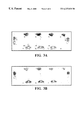
- FIGS. 3A and 3B are digitized plots of autoradiographic images of the block side ( 3 A) and head side ( 3 B) of a gasket following Test A, in which a known coolant leakage condition pre-existed.
- FIGS. 4A and 4B are enlarged areas from the FIGS. 3A and 3B images of the block side ( 4 A) and head side ( 4 B) of the gasket following Test A.
- FIG. 5 is a graph of potential coolant contamination in oil as a function of engine thermal cycle number in Test B, in which a known coolant leakage condition did not pre-exist. The absence of coolant contamination was determined from the absence of radiotracer levels in the oil. Also shown for reference is the radioactivity content in the coolant during the same operating period.
- the tracer species must be readily soluble in engine coolant and must remain suspended in the coolant during engine operation (i.e., not be susceptible to deposition on hot metal surfaces).
- the radioactivity must be able to be measured with high sensitivity in samples of engine coolant and engine oil.
- the radioactive material must provide good imaging capability on photographic film at low concentrations.
- the radiotracer must have a sufficiently long half-life to perform engine studies. (Ideally, the half-life of the species should also be short enough that the fluids and gasket materials can be held for decay rather than require disposal as radioactive waste.)
- Rubidium-86 decays by high-energy ⁇ -emission (E max of 1.775 MeV) which provides for good imaging on photographic film. It also emits a 1.077 MeV ⁇ ray with 8.8% probability per decay, which can be used for its detection in bulk coolant and oil samples. With a half-life of 18.6 days, this species provides approximately one month of useful engine testing, and the 86 Rb in the coolant will decay sufficiently to permit disposal of the coolant without regard to radioactivity after approximately six months.
- a prototype V8 gasoline engine was selected for evaluation of this 86 Rb tracer method.
- the engine had been subjected to an aggressive coolant thermal test cycle for 1400 10-minute cycles and had experienced coolant leaks.
- the engine had been run on a test stand with a coolant heat exchanger that could quickly simulate coolant temperature extremes.
- the heads and head gaskets had been changed and an additional 1200 cycles accumulated.
- visual observations showed no head gasket leakage, and there was no evidence of coolant in the oil pan.
- tests for glycol in the oil [GLY-TEK Test for ethylene glycol, Nelco Company, 1047 McNight Road South, St. Paul, Minn. 55119] consistently reported coolant contamination in the 50-200 ppm range.
- the engine had been assembled with commercial head gaskets having graphite composite only on the block-side of the gasket.
- the gasket about 1.5 mm thick, was formed of a steel sheet with holes cut for cylinders, bolts and coolant passages.
- a compressible, porous graphite composite was applied to one side (cylinder block side) and thin plastic sheets covered both the graphite and bare steel sides.
- Each test schedule consisted of five minutes of operation at 3750 r/min and 50 kPa manifold absolute pressure (MAP) followed by five minutes at 750 r/min and closed throttle.
- MAP manifold absolute pressure
- This cycle was designed to provide the maximum change in coolant temperature within the facility restraints of the dynamometer test cell (240 hp maximum power and engine cooling by tap water through a heat exchanger). During each cycle, the engine coolant fluctuated between a minimum of 46° C. and a maximum of 112° C.
- the first engine test (Test A) during which radiotracer analyses were made consisted of 32 10-min modified thermal cycles. Samples of the engine coolant and oil were obtained after every two or four cycles. After 32 cycles, the radioactive coolant was removed from the engine, and the engine cooling system was flushed with water. The engine was disassembled and the head gaskets removed. Each gasket was carefully removed from the engine to minimize the amount of graphite composite adhering to the block. The gaskets were rinsed with water.
- Test B the engine was reassembled with an original (graphite on one side) gasket on the left cylinder bank and an improved gasket on the right cylinder bank.
- the improved gasket had composite graphite on both sides of the steel substrate with plastic sheets covering the graphite layers.
- the engine was operated for 72 modified cycles without the radiotracer in the coolant. Then, approximately 2 mCi of the 86 Rb tracer was added, and 264 additional modified cycles accumulated. An additional 6 mCi of 86 Rb was then added and the engine run for 24 thermal cycles. Oil and coolant samples were obtained after every 12 cycles of Test B. At the conclusion of the total 360 thermal cycles, the coolant was removed from the engine, the cooling system flushed, and the head gaskets removed.
- Coolant samples were analyzed by dilution of a 1-mL sample into 20 mL of water and counting in a Packard Minaxi 5530 automated ⁇ -ray analyzer which incorporated a shielded 76 ⁇ 76-mm NaI(Tl) detector. The counting window was selected to span the 1.077-MeV peak of 86 Rb. Results were corrected for decay and background. Oil samples of 20-mL volume were counted without dilution using the same analyzer. Samples from Test A were counted for 30 minutes and samples from Test B were counted for 60 minutes.
- each film was converted to a computer image by a digital scanner (Hewlett Packard ScanJet IIc). Individual scans were combined into a composite image (typically 3600 ⁇ 1200 ⁇ 256 pixels) and film-edge artifacts eliminated using image analysis software (Paint Shop Pro, v. 4.14, Jasc, Inc.).
- Results of oil and coolant radioactivity measurements taken during Test A are presented in FIG. 1 .
- Results confirm that the radiotracer concentration in the coolant remains relatively constant over the entire test (see the darkened diamond data points ⁇ recording gamma ray counts per minute corrected for background and decay). Radioactivity in the oil begins to appear after four cycles and accumulates at a linear rate (see the open square data points ⁇ ). The calculation of part-per-million contamination is made under the assumption that all the radiotracer remains suspended in the oil. The detection sensitivity obtained in this first study is better than 100 ppm coolant in oil at 95% confidence.
- FIG. 2 shows line drawings of the left-bank cylinder head 10 (as viewed from the driver seat), cylinder block 12 and gasket 14 . These drawings are shown in a generally exploded or overlying view so as to be useful when interpreting the patterns (see FIGS. 3 and 4) of radioactivity in autoradiograms of the gaskets.
- the line view of the block 12 is like a plan view of the deck surface of the “V” block intended to be enclosed with the left bank cylinder head.
- the cylinder block deck is portrayed as containing four cylinders 16 , sixteen bolt holes 18 , and several water passages 20 of varied sizes.
- gasket 14 shows openings that are complementary to openings in the cylinder block view 12 (and cylinder head view 10 ). Specifically, gasket 14 contains cylinder openings 24 and bolt openings 26 . However, the coolant passage holes 28 in the gasket are by design much smaller than the water passage holes 20 in block 12 . This gasket design is intended to restrict the flow of coolant between block 12 and head 10 .
- the actual gasket is a laminated structure typically comprising a steel sheet or foil with a compressible, somewhat porous graphite composite on at least one side and an outer layer on each side of plastic foil.
- the line drawing of head 10 is an outline or silhouette of the lower surface of a cylinder head adapted to be bolted to the deck of cylinder block 12 and gasket 14 .
- the full cylinder head is not shown because it would complicate the illustration of the abutting surfaces of the head 10 , gasket 14 and block 12 .
- the line drawing of head 10 shows the locations of combustion chambers 30 , bolt holes 32 and water passages 34 .
- coolant is pumped under pressure in jackets (not shown in the line drawing of FIG. 2) around each cylinder and around the combustion chambers and exhaust ports (neither shown in FIG. 2) in the head.
- lubricating oil is circulated around the crank shaft and pistons in the block and around the camshaft(s) and valvetrain in the head.
- a block valley (not shown) next to edge 22 of the deck portion of block 12 .
- FIG. 3 shows autoradiograms obtained from the block and head surfaces of the water-rinsed head gasket from the right cylinder bank following Test A. The darkness of exposure at a given location is proportional to the amount of remaining radiotracer present. Images of a very similar nature were obtained from the gasket on the left bank.
- the gasket should be impregnated first with the tracer wherever there is direct contact between the gasket and an open coolant passage. This is indeed the case for the four areas on the inboard side of each gasket surface (i, j, k, l) and the three areas on the outboard side of each surface (m, n, o).
- a rectangular image on the right side (p) and an irregular shaped image on the left side (q) indicate passages in the head and block that are sealed off by the gasket.
- the images of the block and head side are somewhat different because the block side has a composite graphite layer whereas the head side has only a thin plastic coating on the steel substrate.
- the block side shows a more diffuse image because of the finite depth of the composite material.
- the outboard images on the block side (m, n, o) also show a border around them with no apparent radioactivity. This gap is due to the presence of a thin plastic-coated steel layer in some areas on that side of the gasket, which also serves as a radiation absorber.
- the head side of the gasket shows indications of the coolant pooled in the dimpled indentations from the steel substrate.
- the gasket images also reveal that there are many locations where the tracer extends well beyond the area of direct contact with engine coolant.
- the regions around three of the inboard areas show that tagged coolant extends all the way to the end of the gasket. (See FIG. 2 for line drawing of head gasket 14 .) This is direct evidence of coolant leakage to the inboard side of the head/block interface (next to the block valley), and hence directly into the oiling system. It is also evident in FIG. 3B that these inboard areas are also leaking into the oiling system from the head side of the gasket interface.
- FIG. 4 Shown in FIG. 4 is an enlarged view of the inboard area between the second and third cylinders of the right cylinder bank for both sides of the gasket.
- the outline of the coolant passage through the block (j) and head can be seen.
- the extension of coolant beyond the passage to the end of the gasket is evident from the dark image following the contour of the gasket.
- Some coolant has leaked into the headbolt holes and some tracer is deposited at the edge of the combustion chamber.
- Results of oil and coolant radioactivity measurements taken during Test B are presented in FIG. 5 .
- the plot is similar to that of Test A for the radiotracer activity in the coolant, but there is no evidence of coolant leakage into the oil, even after 250 cycles with tracer in the coolant.
- the major difference between these studies is that prior to Test A, the engine had been run on a regular deep thermal cycle test for 1200 cycles and had a known coolant leakage problem.
- the modified thermal cycling performed on the research dynamometer was not sufficient, or not enough cycles were performed, to cause the onset of coolant leakage into the oil. Because of the higher levels of radiotracer employed and longer sample counting times, the detection level for coolant in oil during Test B was 50 ppm at 95% confidence.
Landscapes
- Physics & Mathematics (AREA)
- General Physics & Mathematics (AREA)
- Gasket Seals (AREA)
Abstract
Description
Claims (8)
Priority Applications (1)
| Application Number | Priority Date | Filing Date | Title |
|---|---|---|---|
| US09/289,920 US6227038B1 (en) | 1999-04-12 | 1999-04-12 | Radiotracer method for measuring leakage of engine coolant |
Applications Claiming Priority (1)
| Application Number | Priority Date | Filing Date | Title |
|---|---|---|---|
| US09/289,920 US6227038B1 (en) | 1999-04-12 | 1999-04-12 | Radiotracer method for measuring leakage of engine coolant |
Publications (1)
| Publication Number | Publication Date |
|---|---|
| US6227038B1 true US6227038B1 (en) | 2001-05-08 |
Family
ID=23113739
Family Applications (1)
| Application Number | Title | Priority Date | Filing Date |
|---|---|---|---|
| US09/289,920 Expired - Fee Related US6227038B1 (en) | 1999-04-12 | 1999-04-12 | Radiotracer method for measuring leakage of engine coolant |
Country Status (1)
| Country | Link |
|---|---|
| US (1) | US6227038B1 (en) |
Cited By (7)
| Publication number | Priority date | Publication date | Assignee | Title |
|---|---|---|---|---|
| US20040182141A1 (en) * | 2003-03-18 | 2004-09-23 | Edp Technical Services, Inc. | Head gasket testing apparatus and method |
| US20050097942A1 (en) * | 2003-11-10 | 2005-05-12 | Meischner Christopher R. | System for monitoring dilution |
| US20060237640A1 (en) * | 2002-12-16 | 2006-10-26 | Totalfinaelf France | Method and device for the continuous determination of damage to systems used for the post-treatment of heat engine exhaust gases |
| US20080226536A1 (en) * | 2002-05-09 | 2008-09-18 | Olivier Smiljanic | Method and apparatus for producing single-wall carbon nanotubes |
| US8393235B2 (en) * | 2011-05-13 | 2013-03-12 | Chrysler Group Llc | Particulate dispersion device for vehicle hardware testing |
| US9127587B2 (en) | 2010-11-30 | 2015-09-08 | General Electric Company | Cooling system for an engine and method of providing a cooling system for an engine |
| US10996134B2 (en) * | 2019-05-31 | 2021-05-04 | GM Global Technology Operations LLC | Coolant leak diagnosis |
Citations (4)
| Publication number | Priority date | Publication date | Assignee | Title |
|---|---|---|---|---|
| US3745338A (en) * | 1964-08-17 | 1973-07-10 | Industrial Nucleonics Corp | Volumetric measuring method and apparatus |
| FR2217684A1 (en) * | 1973-02-14 | 1974-09-06 | Commissariat Energie Atomique | |
| US4746795A (en) * | 1980-11-15 | 1988-05-24 | Rolls-Royce Plc | Method of and apparatus for analyzing fluid flows within hollow bodies |
| US5968371A (en) * | 1998-01-26 | 1999-10-19 | Nelson Industries, Inc. | Lubricant circulation diagnostic and modeling system |
-
1999
- 1999-04-12 US US09/289,920 patent/US6227038B1/en not_active Expired - Fee Related
Patent Citations (4)
| Publication number | Priority date | Publication date | Assignee | Title |
|---|---|---|---|---|
| US3745338A (en) * | 1964-08-17 | 1973-07-10 | Industrial Nucleonics Corp | Volumetric measuring method and apparatus |
| FR2217684A1 (en) * | 1973-02-14 | 1974-09-06 | Commissariat Energie Atomique | |
| US4746795A (en) * | 1980-11-15 | 1988-05-24 | Rolls-Royce Plc | Method of and apparatus for analyzing fluid flows within hollow bodies |
| US5968371A (en) * | 1998-01-26 | 1999-10-19 | Nelson Industries, Inc. | Lubricant circulation diagnostic and modeling system |
Cited By (10)
| Publication number | Priority date | Publication date | Assignee | Title |
|---|---|---|---|---|
| US20080226536A1 (en) * | 2002-05-09 | 2008-09-18 | Olivier Smiljanic | Method and apparatus for producing single-wall carbon nanotubes |
| US20060237640A1 (en) * | 2002-12-16 | 2006-10-26 | Totalfinaelf France | Method and device for the continuous determination of damage to systems used for the post-treatment of heat engine exhaust gases |
| US7402800B2 (en) * | 2002-12-16 | 2008-07-22 | Total Fina Elf France | Method and device for the continuous determination of damage to systems used for the post-treatment of heat engine exhaust gases |
| US20040182141A1 (en) * | 2003-03-18 | 2004-09-23 | Edp Technical Services, Inc. | Head gasket testing apparatus and method |
| US6804996B2 (en) | 2003-03-18 | 2004-10-19 | Edp Technical Services, Inc. | Head gasket testing apparatus and method |
| US20050097942A1 (en) * | 2003-11-10 | 2005-05-12 | Meischner Christopher R. | System for monitoring dilution |
| US7017392B2 (en) * | 2003-11-10 | 2006-03-28 | Caterpillar Inc | System for monitoring dilution |
| US9127587B2 (en) | 2010-11-30 | 2015-09-08 | General Electric Company | Cooling system for an engine and method of providing a cooling system for an engine |
| US8393235B2 (en) * | 2011-05-13 | 2013-03-12 | Chrysler Group Llc | Particulate dispersion device for vehicle hardware testing |
| US10996134B2 (en) * | 2019-05-31 | 2021-05-04 | GM Global Technology Operations LLC | Coolant leak diagnosis |
Similar Documents
| Publication | Publication Date | Title |
|---|---|---|
| US6227038B1 (en) | Radiotracer method for measuring leakage of engine coolant | |
| Schneider et al. | Effect of cylinder bore out-of-roundness on piston ring rotation and engine oil consumption | |
| US2938125A (en) | Wear determination method | |
| US7763850B2 (en) | Method and device for the real-time measurement of the consumption of oil from an engine oil separation system, using radioactive tracers | |
| Hill et al. | A systems approach to oil consumption | |
| Warrick et al. | An advanced radiotracer technique for assessing and plotting oil consumption in diesel and gasoline engines | |
| US7783407B2 (en) | Method and device for monitoring the dilution of the lubricating oil by the fuel in an internal combustion engine | |
| Schneider et al. | Method for measurement of piston ring rotation in an operating engine | |
| Schneider et al. | Applications of nuclear methods in the automotive industry | |
| Bolis et al. | The effect of oil and coolant temperatures on diesel engine wear | |
| Delvigne et al. | A new methodology for on line lubricant consumption measurement | |
| Walch et al. | Multimethod concept for continuous wear-analysis of the piston group | |
| Hudgens et al. | Analysis of coolants from diesel engines | |
| Boateng et al. | Non-destructive evaluation of corrosion on insulated pipe using double wall radiographic technique | |
| Knop | Evaluation of a radiometric method of determining engine oil economy | |
| Lawrence et al. | Radioisotope techniques applied to the investigation of surface contact in rolling element bearings | |
| Baptista et al. | Condition Monitoring of Engines by Lubricating Oil Analysis | |
| Reynolds Jr | The introduction of real-time radiography for the inspection of butt welds in offshore pipelines | |
| Schneider et al. | Real-time measurement of camshaft wear in an automotive engine-a radiometric method | |
| Lycoming et al. | HIGH POWER-DENSITY REDUCTION GEARBOX LUBRICATION STUDIES USING POSITRON EMISSION TOMOGRAPHY | |
| Martz et al. | Three-dimensional nonintrusive imaging of obscured objects by x-ray and gamma-ray computed tomography | |
| Emanuel et al. | New Application of Radiotracer Techniques | |
| Totten et al. | Water-glycol hydraulic fluid evaluation by ASTM D 2882: Significant contributors to erroneous results | |
| SU1437777A1 (en) | Method of determining washing properties of engine oils | |
| Lusted | Direct observation of oil consumption mechanisms in a production spark ignition engine using fluorenscence techniques |
Legal Events
| Date | Code | Title | Description |
|---|---|---|---|
| AS | Assignment |
Owner name: GENERAL MOTORS CORPORATION, MICHIGAN Free format text: ASSIGNMENT OF ASSIGNORS INTEREST;ASSIGNORS:BLOSSFELD, DANIEL HICKS;SCHNEIDER, ERIC WEST;GUSHMAN, RICHARD WILLIAM;REEL/FRAME:009892/0293;SIGNING DATES FROM 19990329 TO 19990330 |
|
| FPAY | Fee payment |
Year of fee payment: 4 |
|
| FPAY | Fee payment |
Year of fee payment: 8 |
|
| AS | Assignment |
Owner name: GM GLOBAL TECHNOLOGY OPERATIONS, INC., MICHIGAN Free format text: ASSIGNMENT OF ASSIGNORS INTEREST;ASSIGNOR:GENERAL MOTORS CORPORATION;REEL/FRAME:022117/0047 Effective date: 20050119 Owner name: GM GLOBAL TECHNOLOGY OPERATIONS, INC.,MICHIGAN Free format text: ASSIGNMENT OF ASSIGNORS INTEREST;ASSIGNOR:GENERAL MOTORS CORPORATION;REEL/FRAME:022117/0047 Effective date: 20050119 |
|
| AS | Assignment |
Owner name: UNITED STATES DEPARTMENT OF THE TREASURY, DISTRICT Free format text: SECURITY AGREEMENT;ASSIGNOR:GM GLOBAL TECHNOLOGY OPERATIONS, INC.;REEL/FRAME:022201/0501 Effective date: 20081231 |
|
| AS | Assignment |
Owner name: CITICORP USA, INC. AS AGENT FOR HEDGE PRIORITY SEC Free format text: SECURITY AGREEMENT;ASSIGNOR:GM GLOBAL TECHNOLOGY OPERATIONS, INC.;REEL/FRAME:022556/0013 Effective date: 20090409 Owner name: CITICORP USA, INC. AS AGENT FOR BANK PRIORITY SECU Free format text: SECURITY AGREEMENT;ASSIGNOR:GM GLOBAL TECHNOLOGY OPERATIONS, INC.;REEL/FRAME:022556/0013 Effective date: 20090409 |
|
| AS | Assignment |
Owner name: GM GLOBAL TECHNOLOGY OPERATIONS, INC., MICHIGAN Free format text: RELEASE BY SECURED PARTY;ASSIGNOR:UNITED STATES DEPARTMENT OF THE TREASURY;REEL/FRAME:023238/0015 Effective date: 20090709 |
|
| XAS | Not any more in us assignment database |
Free format text: RELEASE BY SECURED PARTY;ASSIGNOR:UNITED STATES DEPARTMENT OF THE TREASURY;REEL/FRAME:023124/0383 |
|
| AS | Assignment |
Owner name: GM GLOBAL TECHNOLOGY OPERATIONS, INC., MICHIGAN Free format text: RELEASE BY SECURED PARTY;ASSIGNORS:CITICORP USA, INC. AS AGENT FOR BANK PRIORITY SECURED PARTIES;CITICORP USA, INC. AS AGENT FOR HEDGE PRIORITY SECURED PARTIES;REEL/FRAME:023127/0326 Effective date: 20090814 |
|
| AS | Assignment |
Owner name: UNITED STATES DEPARTMENT OF THE TREASURY, DISTRICT Free format text: SECURITY AGREEMENT;ASSIGNOR:GM GLOBAL TECHNOLOGY OPERATIONS, INC.;REEL/FRAME:023155/0922 Effective date: 20090710 |
|
| AS | Assignment |
Owner name: UAW RETIREE MEDICAL BENEFITS TRUST, MICHIGAN Free format text: SECURITY AGREEMENT;ASSIGNOR:GM GLOBAL TECHNOLOGY OPERATIONS, INC.;REEL/FRAME:023161/0864 Effective date: 20090710 |
|
| AS | Assignment |
Owner name: GM GLOBAL TECHNOLOGY OPERATIONS, INC., MICHIGAN Free format text: RELEASE BY SECURED PARTY;ASSIGNOR:UNITED STATES DEPARTMENT OF THE TREASURY;REEL/FRAME:025245/0273 Effective date: 20100420 Owner name: GM GLOBAL TECHNOLOGY OPERATIONS, INC., MICHIGAN Free format text: RELEASE BY SECURED PARTY;ASSIGNOR:UAW RETIREE MEDICAL BENEFITS TRUST;REEL/FRAME:025311/0680 Effective date: 20101026 |
|
| AS | Assignment |
Owner name: WILMINGTON TRUST COMPANY, DELAWARE Free format text: SECURITY AGREEMENT;ASSIGNOR:GM GLOBAL TECHNOLOGY OPERATIONS, INC.;REEL/FRAME:025327/0222 Effective date: 20101027 |
|
| AS | Assignment |
Owner name: GM GLOBAL TECHNOLOGY OPERATIONS LLC, MICHIGAN Free format text: CHANGE OF NAME;ASSIGNOR:GM GLOBAL TECHNOLOGY OPERATIONS, INC.;REEL/FRAME:025780/0795 Effective date: 20101202 |
|
| REMI | Maintenance fee reminder mailed | ||
| LAPS | Lapse for failure to pay maintenance fees | ||
| LAPS | Lapse for failure to pay maintenance fees |
Free format text: PATENT EXPIRED FOR FAILURE TO PAY MAINTENANCE FEES (ORIGINAL EVENT CODE: EXP.); ENTITY STATUS OF PATENT OWNER: LARGE ENTITY |
|
| STCH | Information on status: patent discontinuation |
Free format text: PATENT EXPIRED DUE TO NONPAYMENT OF MAINTENANCE FEES UNDER 37 CFR 1.362 |
|
| FP | Lapsed due to failure to pay maintenance fee |
Effective date: 20130508 |