US6220548B1 - Deployed equipment modules for satellite architecture improvement - Google Patents

Deployed equipment modules for satellite architecture improvement Download PDF

Info

Publication number
US6220548B1
US6220548B1 US09/153,416 US15341698A US6220548B1 US 6220548 B1 US6220548 B1 US 6220548B1 US 15341698 A US15341698 A US 15341698A US 6220548 B1 US6220548 B1 US 6220548B1
Authority
US
United States
Prior art keywords
modules
module
satellite
radiator
equipment
Prior art date
Legal status (The legal status is an assumption and is not a legal conclusion. Google has not performed a legal analysis and makes no representation as to the accuracy of the status listed.)
Expired - Fee Related
Application number
US09/153,416
Inventor
Nelson L. Hyman
Current Assignee (The listed assignees may be inaccurate. Google has not performed a legal analysis and makes no representation or warranty as to the accuracy of the list.)
UNITED STATES OF AMERICAS NAVY THE, Secretary of
US Department of Navy
Original Assignee
US Department of Navy
Priority date (The priority date is an assumption and is not a legal conclusion. Google has not performed a legal analysis and makes no representation as to the accuracy of the date listed.)
Filing date
Publication date
Application filed by US Department of Navy filed Critical US Department of Navy
Priority to US09/153,416 priority Critical patent/US6220548B1/en
Assigned to NAVY, UNITED STATES OF AMERICA AS REPRESENTED BY THE SECRETARY OF THE, THE reassignment NAVY, UNITED STATES OF AMERICA AS REPRESENTED BY THE SECRETARY OF THE, THE ASSIGNMENT OF ASSIGNORS INTEREST (SEE DOCUMENT FOR DETAILS). Assignors: HYMAN, NELSON L.
Assigned to UNITED STATES OF AMERICAS AS REPRESENTED BY THE SECRETARY OF THE NAVY, THE reassignment UNITED STATES OF AMERICAS AS REPRESENTED BY THE SECRETARY OF THE NAVY, THE ASSIGNMENT OF ASSIGNORS INTEREST (SEE DOCUMENT FOR DETAILS). Assignors: HYMAN, NELSON L.
Application granted granted Critical
Publication of US6220548B1 publication Critical patent/US6220548B1/en
Anticipated expiration legal-status Critical
Expired - Fee Related legal-status Critical Current

Links

Images

Classifications

    • BPERFORMING OPERATIONS; TRANSPORTING
    • B64AIRCRAFT; AVIATION; COSMONAUTICS
    • B64GCOSMONAUTICS; VEHICLES OR EQUIPMENT THEREFOR
    • B64G1/00Cosmonautic vehicles
    • B64G1/22Parts of, or equipment specially adapted for fitting in or to, cosmonautic vehicles
    • B64G1/52Protection, safety or emergency devices; Survival aids
    • B64G1/58Thermal protection, e.g. heat shields
    • BPERFORMING OPERATIONS; TRANSPORTING
    • B64AIRCRAFT; AVIATION; COSMONAUTICS
    • B64GCOSMONAUTICS; VEHICLES OR EQUIPMENT THEREFOR
    • B64G1/00Cosmonautic vehicles
    • B64G1/22Parts of, or equipment specially adapted for fitting in or to, cosmonautic vehicles
    • B64G1/46Arrangements or adaptations of devices for control of environment or living conditions
    • B64G1/50Arrangements or adaptations of devices for control of environment or living conditions for temperature control
    • B64G1/503Radiator panels

Definitions

  • This invention pertains generally to thermal radiators and more specifically to thermal radiators on depolyable equipment modules for satellite application.
  • Deployable thermal radiators are components of conventional, but “cutting edge” technology, temperature control systems. In addition to the usual deployment mechanisms, there must be a means to connect radiator and mainbody thermally, conductively either across the rotating joint-hinge line materials (high conductance is not to be expected), or via heat pipe plumbing between radiator and mainbody through a flexible joint. Deployed radiators and associated plumbing are 100% added mass and carry a high total cost per unit area. To minimize mass and cost, they are usually rather precisely sized for their role as part of a conventional satellite active temperature control system. Excess radiator area to provide for a comfortably large hot case margin is a costly luxury not usually or readily obtained. Fluid loops within lightweight deployed radiators are more susceptible to failure as a result of micrometeorite penetration than heat pipes within, and protected by, satellite structure.
  • the object of this invention is to provide a means for satisfactory temperature control for satellites of high power-to-volume ratios, with nominal external area insufficient for required thermal radiators.
  • DEMSAI deployed equipment modules for satellite architecture improvement
  • This is accomplished by deploying box-shaped structures (modules) stowable within a minimum volume geometry around a “mainbody bus” to accommodate fit into a “small” launch vehicle.
  • Each of the modules' exterior panels can accommodate a radiator surface on its exterior while its interior serves as a mounting deck for equipment packages.
  • FIG. 1 ( a ) shows four-modules in a stowed position around a satellite mainbody “bus”.
  • FIG. 1 ( b ) shows the four-module configuration in its deployed position.
  • FIG. 2 shows an eight-modules in a stowed position around a satellite bus.
  • FIG. 2 ( b ) shows the eight-module configuration in its deployed position.
  • FIG. 3 ( a ) shows a four-module configuration in a stacked position around a satellite bus.
  • FIG. 3 ( b ) shows the four-modules in a partially deployed position.
  • FIG. 3 ( c ) shows the four-modules in a fully deployed flat-plane configuration.
  • FIG. 4 shows an eight-module flat-plane deployment and a central satellite bus.
  • a typical deployed equipment module for satellite architecture improvement (DEMSAI) 10 provides ample thermal radiator area for volume-limited small satellites deploying large-area solar panels (not shown) from a relatively small mainbody.
  • Modules, 12 are deployed from a compact stowed assembly, as shown in FIG. 1 a , to offer each of their side panel exteriors as potential radiator area 14 .
  • All rectangular-box-shaped equipment packages of temperature sensitive equipment mount to the interior of these modules 12 and a thermal radiation area 14 forms the outer surface.
  • the modules 12 with the interior equipment packages and the exterior radiator areas 14 share approximately same area.
  • a temperature control method such as that shown in U.S. Pat. No. 5,535,815, Hyman, Jul. 16, 1996, would provide a sufficient transfer of internal heat to the module's 12 exterior radiator area 14 .
  • a satellite (not shown) would usually be a “minimum volume” configuration (approximately cubical in shape) in the stowed non-deployed launch configuration, as shown in FIG. 1 ( a ).
  • Deployable solar panels (not shown)are typically stowed parallel to the plane of the figures, “o” indicating a panel rotation-arm axis on a satellite.
  • Each deployable module 12 has a potential for each of its panels to be a mounting deck with a radiator area 14 exterior, albeit with possible radiative flux input from sun, Earth, and module neighbors.
  • the power dissipation capacity of the total of deployed modules 12 contained within the “stowed launch volume” is much larger than that found in a conventional satellite configuration.
  • the four modules 12 each deploy, as shown in FIG. 1 ( b ), in turn, through a 90° rotation, forming an extended array of modules 12 , exposing the exterior radiator areas 14 to a space sink.
  • the resultant increase in radiator area 14 translates to an increase in the power-handling capacity of small, fixed-body satellites (not shown) without resort to additionally deployed radiators.
  • an 8-module configuration 20 is shown in the stowed position in FIG. 2 ( a ) and deployed in FIG. 2 ( b ), each module 12 of the 4-module configuration shown in FIG. 1 ( b ) becomes two, with one going through an additional 180° deployment, for a total of eight fully deployed separate modules 12 and a significant increase in external radiation area 14 .
  • FIG. 3 ( a ) Another preferred embodiment 30 in a stowed configuration provides a larger effective area, helped by zero intra-module thermal radiation.
  • four modules 12 unfold in two-steps; first, as shown in FIG. 3 ( b ); then unfold into a four module 12 planar configuration, as shown in FIG. 3 ( c ).
  • Another embodiment 40 demonstrates that the area increase utilizing such a configuration may be theoretically unlimited, as this configuration may be applied for any number of modules 12 ; eight are shown in FIG. 4 .
  • the deployed modules 12 receive direct and reflected radiative flux from Earth and Sun. Because the module 12 external radiative environment is variable and satellite-particular, there are many variations of the basic concept as shown in the described embodiments.
  • the technology for module-to-mainbody bus 16 or module-to-module connections with electrical or optical fiber cabling (not shown), radio frequency connections (not shown), or propellant lines (not shown) is well developed and well known to those skilled in the art.
  • the mechanical deployment items such as springs, hinges, and release mechanisms (not shown) are commercially available and flight demonstrated (e.g., for solar cell arrays) and well known to those skilled in the art.
  • radiator area 14 With adequate radiator area 14 and heater power, the simplest, most familiar, and most easily implemented conventional thermal control system for relatively small box-shape modules 12 is the semi-active, based on radiator area 14 sized for satisfactory hot-case temperatures and thermostatically-controlled heaters to maintain cold-case temperatures.
  • Each internal package of the modules 12 is dedicated to a specific radiator 14 on the external deck surface opposite its mounting footprint.
  • the radiator area 14 exposed can be smaller or larger than this footprint.
  • a multi-layer-insulation (MLI) thermal blanket (not shown) covers all module 12 external area that is not devoted to radiator area 14 .
  • Required radiator area 14 is calculated in the thermal design process, and all “excess” external area beyond this is MLI covered. Lateral heat conduction through the module 12 mounting decks (not shown) may require augmentation. This is well known to those skilled in the art.
  • the deployed-module 12 architecture has merit for satellites (not shown) requiring radiator area 14 beyond that on a small-volume, limited-area mainbody.
  • Modules 12 and their stowed assembly and deploying arrangement may be configured for virtually any number of modules 12 and deployments to provide for any conceivable required radiator area 14 heat rejection.
  • the radiator area 14 increases of the preferred embodiments herein described range from approximately 50 to 300%. Area increase is sensitive to module 14 length-to-height aspect ratio.
  • equipment module 12 deployment (the release and rotation of a box-shaped module 12 about a hinge line shared with its mainbody or another module 14 ) is a simple mechanical function involving non-exotic release mechanisms, hinges, springs, etc. State-of-the-art hardware and precautions assure that the flexible electrical cables and propellant lines connecting modules 12 do not interfere with deployment while maintaining electrical or fluid-pressure integrity.
  • a module 12 carries its own radiaton area 14 (mounting deck exteriors) at no cost in “added” satellite mass, unlike deployed radiators.
  • DEMSAI 10 lends itself readily to the modular, or common bus 16 concept based on a hinged and deployed structural framework, with provisions for cabling and connectors, into which identically configured modules 12 are readily inserted and removed.
  • DEMSAI 10 provides external area for mounting a multitude of antennas or sensors, and provides increased satellite dimensions for greater attitude control thruster moment-arm and gravity-gradient stabilization. Virtually any radiator area 14 (or satellite breadth) increase relative to the original satellite mainbody may be achieved using the DEMSAI 10 concept.
  • This concept of increasing thermal radiating area 14 through deployment of equipment modules 12 is not restricted to any particular satellite geometry, and it can be utilized to achieve virtually any reasonably large increase in radiator area 14 to suit a particular power and temperature requirement of a satellite payload.
  • the plurality of deployed modules 12 has a combined total area of exposed radiators that is adequately and sufficiently large enough for temperature control of the power dissipating mounted equipment.

Landscapes

  • Engineering & Computer Science (AREA)
  • General Health & Medical Sciences (AREA)
  • Aviation & Aerospace Engineering (AREA)
  • Health & Medical Sciences (AREA)
  • Remote Sensing (AREA)
  • Critical Care (AREA)
  • Emergency Medicine (AREA)
  • Physics & Mathematics (AREA)
  • Thermal Sciences (AREA)
  • Life Sciences & Earth Sciences (AREA)
  • Biodiversity & Conservation Biology (AREA)
  • Environmental & Geological Engineering (AREA)
  • Environmental Sciences (AREA)
  • Toxicology (AREA)
  • Photovoltaic Devices (AREA)

Abstract

Deployed equipment modules for satellite architecture improvement (DEMSAI) provide ample thermal radiator for area-limited small satellites that typically deploy large-area solar panels from a relatively small mainbody. Rectangular-box-shaped equipment modules are deployed from a compact stowed assembly to offer each of their six side panel exteriors as potential radiator area. Equipment packages are mounted to the interior of these panels. The resultant increase in radiator area translates to an increase in the power-handling capacity of small, fixed-body satellites without resort to deployed radiators.

Description

BACKGROUND OF THE INVENTION
1. Field of the Invention
This invention pertains generally to thermal radiators and more specifically to thermal radiators on depolyable equipment modules for satellite application.
2. Description of the Related Art
Organizations developing small satellites are faced with dense packaging of on-board equipment and deploying large and light solar arrays from small stowage volumes. The trends in electronics miniaturization, denser component packaging, increasing solar array deployed area-to-stowed volume ratio, and even smaller and lighter satellites and launch vehicles are resulting in a higher ratio of power dissipation to satellite body volume. Electrical power dissipation must ultimately be thermally radiated from a satellite to the space sink by way of external radiating surfaces (radiators), and the inviolate laws of physics dictate the watts per unit area upper limit.
Deployable thermal radiators are components of conventional, but “cutting edge” technology, temperature control systems. In addition to the usual deployment mechanisms, there must be a means to connect radiator and mainbody thermally, conductively either across the rotating joint-hinge line materials (high conductance is not to be expected), or via heat pipe plumbing between radiator and mainbody through a flexible joint. Deployed radiators and associated plumbing are 100% added mass and carry a high total cost per unit area. To minimize mass and cost, they are usually rather precisely sized for their role as part of a conventional satellite active temperature control system. Excess radiator area to provide for a comfortably large hot case margin is a costly luxury not usually or readily obtained. Fluid loops within lightweight deployed radiators are more susceptible to failure as a result of micrometeorite penetration than heat pipes within, and protected by, satellite structure.
SUMMARY OF THE INVENTION
The object of this invention is to provide a means for satisfactory temperature control for satellites of high power-to-volume ratios, with nominal external area insufficient for required thermal radiators.
This and other objectives are accomplished by deployed equipment modules for satellite architecture improvement (DEMSAI) which increases the external thermal-radiator area of a satellite and increases the satellite's capacity for high density equipment packaging and total electrical power while providing satisfactory temperature control. This is accomplished by deploying box-shaped structures (modules) stowable within a minimum volume geometry around a “mainbody bus” to accommodate fit into a “small” launch vehicle. Each of the modules' exterior panels can accommodate a radiator surface on its exterior while its interior serves as a mounting deck for equipment packages.
BRIEF DESCRIPTION OF THE DRAWINGS
FIG. 1(a) shows four-modules in a stowed position around a satellite mainbody “bus”.
FIG. 1(b) shows the four-module configuration in its deployed position.
FIG. 2 shows an eight-modules in a stowed position around a satellite bus.
FIG. 2(b) shows the eight-module configuration in its deployed position.
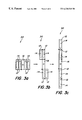
FIG. 3(a) shows a four-module configuration in a stacked position around a satellite bus.
FIG. 3(b) shows the four-modules in a partially deployed position.
FIG. 3(c) shows the four-modules in a fully deployed flat-plane configuration.
FIG. 4 shows an eight-module flat-plane deployment and a central satellite bus.
DESCRIPTION OF THE PREFERRED EMBODIMENT
A typical deployed equipment module for satellite architecture improvement (DEMSAI) 10 provides ample thermal radiator area for volume-limited small satellites deploying large-area solar panels (not shown) from a relatively small mainbody. Modules, 12 are deployed from a compact stowed assembly, as shown in FIG. 1a, to offer each of their side panel exteriors as potential radiator area 14. All rectangular-box-shaped equipment packages of temperature sensitive equipment mount to the interior of these modules 12 and a thermal radiation area 14 forms the outer surface. The modules 12 with the interior equipment packages and the exterior radiator areas 14 share approximately same area. A temperature control method, such as that shown in U.S. Pat. No. 5,535,815, Hyman, Jul. 16, 1996, would provide a sufficient transfer of internal heat to the module's 12 exterior radiator area 14.
In the preferred embodiment of a DEMSAI 10, a satellite (not shown) would usually be a “minimum volume” configuration (approximately cubical in shape) in the stowed non-deployed launch configuration, as shown in FIG. 1(a). Deployable solar panels (not shown)are typically stowed parallel to the plane of the figures, “o” indicating a panel rotation-arm axis on a satellite. Each deployable module 12 has a potential for each of its panels to be a mounting deck with a radiator area 14 exterior, albeit with possible radiative flux input from sun, Earth, and module neighbors. The power dissipation capacity of the total of deployed modules 12 contained within the “stowed launch volume” is much larger than that found in a conventional satellite configuration.
After launch, the four modules 12 each deploy, as shown in FIG. 1(b), in turn, through a 90° rotation, forming an extended array of modules 12, exposing the exterior radiator areas 14 to a space sink. The resultant increase in radiator area 14 translates to an increase in the power-handling capacity of small, fixed-body satellites (not shown) without resort to additionally deployed radiators.
In another embodiment, an 8-module configuration 20 is shown in the stowed position in FIG. 2(a) and deployed in FIG. 2(b), each module 12 of the 4-module configuration shown in FIG. 1(b) becomes two, with one going through an additional 180° deployment, for a total of eight fully deployed separate modules 12 and a significant increase in external radiation area 14.
Another preferred embodiment 30, as shown in FIG. 3(a) in a stowed configuration provides a larger effective area, helped by zero intra-module thermal radiation. In this embodiment 30, four modules 12 unfold in two-steps; first, as shown in FIG. 3(b); then unfold into a four module 12 planar configuration, as shown in FIG. 3(c).
Another embodiment 40 demonstrates that the area increase utilizing such a configuration may be theoretically unlimited, as this configuration may be applied for any number of modules 12; eight are shown in FIG. 4.
The deployed modules 12 receive direct and reflected radiative flux from Earth and Sun. Because the module 12 external radiative environment is variable and satellite-particular, there are many variations of the basic concept as shown in the described embodiments. The technology for module-to-mainbody bus 16 or module-to-module connections with electrical or optical fiber cabling (not shown), radio frequency connections (not shown), or propellant lines (not shown) is well developed and well known to those skilled in the art. The mechanical deployment items such as springs, hinges, and release mechanisms (not shown) are commercially available and flight demonstrated (e.g., for solar cell arrays) and well known to those skilled in the art.
With adequate radiator area 14 and heater power, the simplest, most familiar, and most easily implemented conventional thermal control system for relatively small box-shape modules 12 is the semi-active, based on radiator area 14 sized for satisfactory hot-case temperatures and thermostatically-controlled heaters to maintain cold-case temperatures. Each internal package of the modules 12 is dedicated to a specific radiator 14 on the external deck surface opposite its mounting footprint. The radiator area 14 exposed can be smaller or larger than this footprint. A multi-layer-insulation (MLI) thermal blanket (not shown) covers all module 12 external area that is not devoted to radiator area 14. Required radiator area 14 is calculated in the thermal design process, and all “excess” external area beyond this is MLI covered. Lateral heat conduction through the module 12 mounting decks (not shown) may require augmentation. This is well known to those skilled in the art.
Active temperature control (to minimize heater power requirements) in the form of radiator-covering, emittance-modulating “louvers,” is possible in the design, but these devices have traditionally been burdened with low effectiveness, imprecise temperature feedback, complexity, high mass and cost, and limited reliability.
The concept of providing each individual equipment package in a module 12 with an active control thermal switch (not shown) to modulate package-to-deck thermal conductance as a function of module 12 package temperature (isolating packages from module 12 mounting decks (not shown) during cold conditions) is a most feasible approach for an active thermal control system (TCS). This concept will provide for a cold case heater power lower than any contemporary semi-active or active TCS, such as that found in U.S. Pat. No. 5,535,815, and makes highly efficient uses of radiator area on external surfaces directly opposite package mounting footprints. Unlike the semi-active TCS, external area may be devoted totally to a radiator area 14, since there is no viable concern with a “too-cold” equipment mounting panel (not shown).
The deployed-module 12 architecture has merit for satellites (not shown) requiring radiator area 14 beyond that on a small-volume, limited-area mainbody. Modules 12 and their stowed assembly and deploying arrangement may be configured for virtually any number of modules 12 and deployments to provide for any conceivable required radiator area 14 heat rejection. The radiator area 14 increases of the preferred embodiments herein described range from approximately 50 to 300%. Area increase is sensitive to module 14 length-to-height aspect ratio.
When compared to deploying radiators with their demanding requirements for heat transport across the hinge line and complex heat transport paths of fluid lines, equipment module 12 deployment (the release and rotation of a box-shaped module 12 about a hinge line shared with its mainbody or another module 14) is a simple mechanical function involving non-exotic release mechanisms, hinges, springs, etc. State-of-the-art hardware and precautions assure that the flexible electrical cables and propellant lines connecting modules 12 do not interfere with deployment while maintaining electrical or fluid-pressure integrity.
A module 12 carries its own radiaton area 14 (mounting deck exteriors) at no cost in “added” satellite mass, unlike deployed radiators. DEMSAI 10 lends itself readily to the modular, or common bus 16 concept based on a hinged and deployed structural framework, with provisions for cabling and connectors, into which identically configured modules 12 are readily inserted and removed. The excess-radiator-area module 12 with temperature control for its mounting decks (not shown), or individual actively controlled thermal switches (not shown) for each mounted package, fit the definition of “thermal bus”.
Further, DEMSAI 10 provides external area for mounting a multitude of antennas or sensors, and provides increased satellite dimensions for greater attitude control thruster moment-arm and gravity-gradient stabilization. Virtually any radiator area 14 (or satellite breadth) increase relative to the original satellite mainbody may be achieved using the DEMSAI 10 concept.
This concept of increasing thermal radiating area 14 through deployment of equipment modules 12 is not restricted to any particular satellite geometry, and it can be utilized to achieve virtually any reasonably large increase in radiator area 14 to suit a particular power and temperature requirement of a satellite payload. The plurality of deployed modules 12 has a combined total area of exposed radiators that is adequately and sufficiently large enough for temperature control of the power dissipating mounted equipment.
Although the invention has been described in relation to an exemplary embodiment thereof, it will be understood by those skilled in the art that still other variations and modifications can be affected in the preferred embodiment without detracting from the scope and spirit of the invention as described in the claims.

Claims (8)

What is claimed is:
1. Deployable equipment modules for a satellite comprised of:
a plurality of modules stowed in a folded position around a common bus prior to launch of the satellite;
a temperature sensitive equipment package mounted internally on each module of the plurality of modules;
each module having an external thermal radiator area to control the package temperature within predetermined limits; and
means for deploying the modules to form an extended array of modules exposing the radiator areas to a space sink after the satellite reaches orbital condition.
2. A deployable equipment module, as in claim 1, wherein the means for deploying the modules to form an extended array of modules is a system of non-exotic release mechanisms, hinges, and springs.
3. A deployable equipment module, as in claim 1, wherein each temperature sensitive equipment package is further comprised of an active temperature control device.
4. A deployable equipment module, as in claim 1, wherein each temperature sensitive equipment package is further comprised of a semi-active temperature control device.
5. A deployable equipment module, as in claim 1, wherein each module is further comprised of a multi-layer-insulation thermal blanket covering all module external areas not devoted to radiator area.
6. Deployable equipment modules for a satellite comprised of:
a plurality of modules stowed in a folded position around a common bus prior to launch of the satellite;
a temperature sensitive equipment package mounted internally on each module of the plurality of modules;
each temperature sensitive equipment package having an active temperature control device;
each module having a external thermal radiator area to control the package temperature within predetermined limits;
a multi-layer-insulation thermal blanket covering all module external areas not devoted to radiator area; and
a system of non-exotic release mechanisms, hinges, and springs for deploying the modules to form an extended array of modules exposing the radiator areas to a space sink after the satellite reaches orbital condition.
7. Deployable equipment modules for a satellite comprised of:
a plurality of modules stowed in a folded position around a common bus prior to launch of the satellite;
a temperature sensitive equipment package mounted internally on each module of the plurality of modules;
each temperature sensitive equipment package having a semi-active temperature control device;
each module having a external thermal radiator area to control the package temperature within predetermined limits;
a multi-layer-insulation thermal blanket covering all module external areas not devoted to radiator area; and
a system of non-exotic release mechanisms, hinges, and springs for deploying the modules to form an extended array of modules exposing the radiator areas to a space sink after the satellite reaches orbital condition.
8. A method for deploying equipment modules on a satellite to control temperature of the equipment within predetermined limits; comprising the steps of:
mounting a temperature sensitive equipment package internally on each module of a plurality of modules;
stowing the plurality of modules in a folded position around a common bus prior to launch of the satellite; and
deploying the modules to form an extended array of modules exposing an external radiator area of the modules to a space sink after the satellite reaches orbital condition.
US09/153,416 1998-09-14 1998-09-14 Deployed equipment modules for satellite architecture improvement Expired - Fee Related US6220548B1 (en)

Priority Applications (1)

Application Number Priority Date Filing Date Title
US09/153,416 US6220548B1 (en) 1998-09-14 1998-09-14 Deployed equipment modules for satellite architecture improvement

Applications Claiming Priority (1)

Application Number Priority Date Filing Date Title
US09/153,416 US6220548B1 (en) 1998-09-14 1998-09-14 Deployed equipment modules for satellite architecture improvement

Publications (1)

Publication Number Publication Date
US6220548B1 true US6220548B1 (en) 2001-04-24

Family

ID=22547134

Family Applications (1)

Application Number Title Priority Date Filing Date
US09/153,416 Expired - Fee Related US6220548B1 (en) 1998-09-14 1998-09-14 Deployed equipment modules for satellite architecture improvement

Country Status (1)

Country Link
US (1) US6220548B1 (en)

Cited By (21)

* Cited by examiner, † Cited by third party
Publication number Priority date Publication date Assignee Title
US6318674B1 (en) * 2000-03-02 2001-11-20 The Aerospace Corporation Power sphere deployment method
US20020153128A1 (en) * 2001-04-24 2002-10-24 Lenny Low Spacecraft radiator system and method using cross-coupled deployable thermal radiators
US6669147B2 (en) * 2001-04-05 2003-12-30 Alcatel Deployable radiator for a space vehicle
RU2247683C1 (en) * 2003-05-21 2005-03-10 Федеральное государственное унитарное предприятие "Государственный космический научно-производственный центр им. М.В. Хруничева" Module-type spacecraft
US20050194122A1 (en) * 2004-03-03 2005-09-08 Wert Kevin L. Heat pipe component deployed from a compact volume
US20070221787A1 (en) * 2006-03-21 2007-09-27 Mckinnon Douglas V Satellite with deployable, articulatable thermal radiators
US20080217483A1 (en) * 2007-02-26 2008-09-11 Thales Thermal control device on board a spacecraft
RU2410294C2 (en) * 2008-12-30 2011-01-27 Сергей Николаевич Абушенко Space platform
US20110240802A1 (en) * 2008-11-26 2011-10-06 Spas Balinov Device for transporting and ejecting small space payloads
US20120012711A1 (en) * 2010-07-16 2012-01-19 The Boeing Company Dual evolved expendable launch vehicle (eelv) secondary payload adaptor (espa) port small satellite design
RU2481254C2 (en) * 2011-08-05 2013-05-10 Открытое акционерное общество "Информационные спутниковые системы" имени академика М.Ф. Решетнева" Spaceship thermal simulator
US20140097981A1 (en) * 2012-10-05 2014-04-10 Thales Satellite with deployable payload modules
CN106553773A (en) * 2016-10-28 2017-04-05 深圳航天东方红海特卫星有限公司 A kind of reversible locking radiation thermal control mechanism
CN107914895A (en) * 2017-09-08 2018-04-17 兰州空间技术物理研究所 A kind of geostationary orbit spacecraft potential controlling apparatus and method
US20180341604A1 (en) * 2017-05-24 2018-11-29 Thales Digital processing device with high connectivity and incoming/outgoing throughput embedded aboard a space platform and split up into mutually interconnected modular processing islets which are remote from one another on the scale of the platform
JPWO2018116490A1 (en) * 2016-12-19 2019-03-28 三菱電機株式会社 Deployable radiator
US10773835B2 (en) 2017-11-30 2020-09-15 Raytheon Company Flexible satellite for deployment from attachment hub
US11214388B2 (en) * 2019-01-09 2022-01-04 Raytheon Company Self-contained payload accommodation module
CN114684392A (en) * 2022-05-10 2022-07-01 椭圆时空(北京)科技有限公司 A backside cooling system for satellite solar panels
US20230234724A1 (en) * 2022-01-21 2023-07-27 Maxar Space Llc Satellite with modular radiator panels
US20240384947A1 (en) * 2023-05-16 2024-11-21 Macdonald, Dettwiler And Associates Inc. Thermal radiator shutter and system and method for thermal control using a thermal radiator shutter

Citations (7)

* Cited by examiner, † Cited by third party
Publication number Priority date Publication date Assignee Title
US4832113A (en) * 1988-03-11 1989-05-23 The United States Of America As Represented By The United States Department Of Energy Survivable pulse power space radiator
US4860467A (en) 1988-05-24 1989-08-29 Larson James D Stretching frame with adhesive fastening of a fabric workpiece
US5027892A (en) * 1989-07-13 1991-07-02 Sundstrand Corporation Petal deployable radiator system for spacecraft
US5441069A (en) 1994-02-07 1995-08-15 Bill Moss, Inc. Tension fabric structure with arches
US5671791A (en) 1995-08-14 1997-09-30 Lapointe; Serge Awning tensioning structure
US5806800A (en) * 1995-12-22 1998-09-15 Caplin; Glenn N. Dual function deployable radiator cover
US5931418A (en) * 1996-12-20 1999-08-03 Trw Inc. Functionally independent spacecraft module

Patent Citations (7)

* Cited by examiner, † Cited by third party
Publication number Priority date Publication date Assignee Title
US4832113A (en) * 1988-03-11 1989-05-23 The United States Of America As Represented By The United States Department Of Energy Survivable pulse power space radiator
US4860467A (en) 1988-05-24 1989-08-29 Larson James D Stretching frame with adhesive fastening of a fabric workpiece
US5027892A (en) * 1989-07-13 1991-07-02 Sundstrand Corporation Petal deployable radiator system for spacecraft
US5441069A (en) 1994-02-07 1995-08-15 Bill Moss, Inc. Tension fabric structure with arches
US5671791A (en) 1995-08-14 1997-09-30 Lapointe; Serge Awning tensioning structure
US5806800A (en) * 1995-12-22 1998-09-15 Caplin; Glenn N. Dual function deployable radiator cover
US5931418A (en) * 1996-12-20 1999-08-03 Trw Inc. Functionally independent spacecraft module

Non-Patent Citations (1)

* Cited by examiner, † Cited by third party
Title
Hyman; An Alternative To Deployed Thermal Radiators: Deployed Equipment Modules With Individual Package Temperature ; 11th AIAA/USU Conference On Small Satellites; pp. 1-2; Sep. 1997.

Cited By (36)

* Cited by examiner, † Cited by third party
Publication number Priority date Publication date Assignee Title
US6318674B1 (en) * 2000-03-02 2001-11-20 The Aerospace Corporation Power sphere deployment method
US6669147B2 (en) * 2001-04-05 2003-12-30 Alcatel Deployable radiator for a space vehicle
US20020153128A1 (en) * 2001-04-24 2002-10-24 Lenny Low Spacecraft radiator system and method using cross-coupled deployable thermal radiators
US6854510B2 (en) * 2001-04-24 2005-02-15 Space Systems/Loral, Inc. Spacecraft radiator system and method using cross-coupled deployable thermal radiators
RU2247683C1 (en) * 2003-05-21 2005-03-10 Федеральное государственное унитарное предприятие "Государственный космический научно-производственный центр им. М.В. Хруничева" Module-type spacecraft
US20060201654A1 (en) * 2004-03-03 2006-09-14 Wert Kevin L Heat pipe component deployed from a compact volume
WO2005094224A3 (en) * 2004-03-03 2005-12-08 Thermal Corp Heat pipe component deployed from a compact volume
US7080681B2 (en) * 2004-03-03 2006-07-25 Thermal Corp. Heat pipe component deployed from a compact volume
US20050194122A1 (en) * 2004-03-03 2005-09-08 Wert Kevin L. Heat pipe component deployed from a compact volume
US20070221787A1 (en) * 2006-03-21 2007-09-27 Mckinnon Douglas V Satellite with deployable, articulatable thermal radiators
US7874520B2 (en) * 2006-03-21 2011-01-25 Lockheed Martin Corporation Satellite with deployable, articulatable thermal radiators
US20080217483A1 (en) * 2007-02-26 2008-09-11 Thales Thermal control device on board a spacecraft
US8616271B2 (en) * 2007-02-26 2013-12-31 Thales Thermal control device on board a spacecraft
US20110240802A1 (en) * 2008-11-26 2011-10-06 Spas Balinov Device for transporting and ejecting small space payloads
RU2410294C2 (en) * 2008-12-30 2011-01-27 Сергей Николаевич Абушенко Space platform
US20120012711A1 (en) * 2010-07-16 2012-01-19 The Boeing Company Dual evolved expendable launch vehicle (eelv) secondary payload adaptor (espa) port small satellite design
US8550408B2 (en) * 2010-07-16 2013-10-08 The Boeing Company Dual evolved expendable launch vehicle (EELV) secondary payload adaptor (ESPA) port small satellite design
RU2481254C2 (en) * 2011-08-05 2013-05-10 Открытое акционерное общество "Информационные спутниковые системы" имени академика М.Ф. Решетнева" Spaceship thermal simulator
US20140097981A1 (en) * 2012-10-05 2014-04-10 Thales Satellite with deployable payload modules
US9650160B2 (en) * 2012-10-05 2017-05-16 Thales Satellite with deployable payload modules
CN106553773B (en) * 2016-10-28 2019-05-07 深圳航天东方红海特卫星有限公司 A kind of reversible locking radiation thermal control mechanism
CN106553773A (en) * 2016-10-28 2017-04-05 深圳航天东方红海特卫星有限公司 A kind of reversible locking radiation thermal control mechanism
US11492145B2 (en) 2016-12-19 2022-11-08 Mitsubishi Electric Corporation Deployable radiator
EP3556666A4 (en) * 2016-12-19 2019-11-13 Mitsubishi Electric Corporation DEPLOYABLE RADIATOR
JPWO2018116490A1 (en) * 2016-12-19 2019-03-28 三菱電機株式会社 Deployable radiator
US10664423B2 (en) * 2017-05-24 2020-05-26 Thales Digital processing device with high connectivity and incoming/outgoing throughput embedded aboard a space platform and split up into mutually interconnected modular processing islets which are remote from one another on the scale of the platform
US20180341604A1 (en) * 2017-05-24 2018-11-29 Thales Digital processing device with high connectivity and incoming/outgoing throughput embedded aboard a space platform and split up into mutually interconnected modular processing islets which are remote from one another on the scale of the platform
CN107914895B (en) * 2017-09-08 2019-03-08 兰州空间技术物理研究所 A potential control device and method for a geosynchronous orbit spacecraft
CN107914895A (en) * 2017-09-08 2018-04-17 兰州空间技术物理研究所 A kind of geostationary orbit spacecraft potential controlling apparatus and method
US10773835B2 (en) 2017-11-30 2020-09-15 Raytheon Company Flexible satellite for deployment from attachment hub
US11214388B2 (en) * 2019-01-09 2022-01-04 Raytheon Company Self-contained payload accommodation module
US20230234724A1 (en) * 2022-01-21 2023-07-27 Maxar Space Llc Satellite with modular radiator panels
US12017806B2 (en) * 2022-01-21 2024-06-25 Maxar Space Llc Satellite with modular radiator panels
CN114684392A (en) * 2022-05-10 2022-07-01 椭圆时空(北京)科技有限公司 A backside cooling system for satellite solar panels
US20240384947A1 (en) * 2023-05-16 2024-11-21 Macdonald, Dettwiler And Associates Inc. Thermal radiator shutter and system and method for thermal control using a thermal radiator shutter
US12545441B2 (en) * 2023-05-16 2026-02-10 Macdonald, Dettwiler And Associates Inc. Thermal radiator shutter and system and method for thermal control using a thermal radiator shutter

Similar Documents

Publication Publication Date Title
US6220548B1 (en) Deployed equipment modules for satellite architecture improvement
EP0780304B1 (en) Dual function deployable radiator and radiator cover
US5979833A (en) Modular spacecraft architecture
AU2020275316B2 (en) Thermal management system for structures in space
US5518209A (en) Multi-mission spacecraft bus having space frame structural design
JP4308478B2 (en) Deployable spacecraft radiator
RU2092398C1 (en) Module-construction space vehicle
US6394395B1 (en) Combination solar array assembly and antenna for a satellite
US5833175A (en) Spacecraft with large east-west dimensions
US6073887A (en) High power spacecraft with full utilization of all spacecraft surfaces
US7028953B2 (en) Two-sided deployable thermal radiator system and method
US11072441B2 (en) Stackable spacecraft
US20120205492A1 (en) Satellite Having Multiple Aspect Ratios
US9889951B1 (en) Spacecraft east-west radiator assembly
WO2017169080A1 (en) Heat dissipation device using heat pipe panel
EP0849169A1 (en) Functionally independent spacecraft module
US5634612A (en) Earth orbiting satellite having electrical energy storage batteries
EP4252321A1 (en) Direct radiating array ("dra") antenna, method of assembling a dra antenna, and system for managing heat generated by a dra antenna
Novak et al. Development of a thermal control architecture for the Mars Exploration Rovers
US6854510B2 (en) Spacecraft radiator system and method using cross-coupled deployable thermal radiators
US12227313B2 (en) Fold-out satellite with integrated radiator panel
US20050077432A1 (en) Dual conduction heat dissipating system for a spacecraft
US12017806B2 (en) Satellite with modular radiator panels
US20260035106A1 (en) Spacecraft platform structure
Baker et al. Lunar Reconnaissance Orbiter (LRO) rapid thermal design development

Legal Events

Date Code Title Description
AS Assignment

Owner name: NAVY, UNITED STATES OF AMERICA AS REPRESENTED BY T

Free format text: ASSIGNMENT OF ASSIGNORS INTEREST;ASSIGNOR:HYMAN, NELSON L.;REEL/FRAME:009613/0149

Effective date: 19980916

AS Assignment

Owner name: UNITED STATES OF AMERICAS AS REPRESENTED BY THE SE

Free format text: ASSIGNMENT OF ASSIGNORS INTEREST;ASSIGNOR:HYMAN, NELSON L.;REEL/FRAME:010605/0203

Effective date: 19980916

FPAY Fee payment

Year of fee payment: 4

REMI Maintenance fee reminder mailed
LAPS Lapse for failure to pay maintenance fees
STCH Information on status: patent discontinuation

Free format text: PATENT EXPIRED DUE TO NONPAYMENT OF MAINTENANCE FEES UNDER 37 CFR 1.362

FP Lapsed due to failure to pay maintenance fee

Effective date: 20090424