US6219082B1 - Printer raster output scanning system with differential screw micron level bow correction - Google Patents
Printer raster output scanning system with differential screw micron level bow correction Download PDFInfo
- Publication number
- US6219082B1 US6219082B1 US09/458,150 US45815099A US6219082B1 US 6219082 B1 US6219082 B1 US 6219082B1 US 45815099 A US45815099 A US 45815099A US 6219082 B1 US6219082 B1 US 6219082B1
- Authority
- US
- United States
- Prior art keywords
- mirror
- screw
- bow
- gripping
- screw shaft
- Prior art date
- Legal status (The legal status is an assumption and is not a legal conclusion. Google has not performed a legal analysis and makes no representation as to the accuracy of the status listed.)
- Expired - Lifetime
Links
- 238000012937 correction Methods 0.000 title abstract description 24
- 239000011295 pitch Substances 0.000 claims abstract description 17
- 108091008695 photoreceptors Proteins 0.000 claims description 15
- 230000003287 optical effect Effects 0.000 claims description 6
- 230000006872 improvement Effects 0.000 claims description 3
- 238000004519 manufacturing process Methods 0.000 abstract description 4
- 238000012986 modification Methods 0.000 abstract description 3
- 230000004048 modification Effects 0.000 abstract description 3
- 229910000831 Steel Inorganic materials 0.000 description 4
- 230000007246 mechanism Effects 0.000 description 4
- 238000000034 method Methods 0.000 description 4
- 239000010959 steel Substances 0.000 description 4
- 230000008859 change Effects 0.000 description 2
- 239000003086 colorant Substances 0.000 description 2
- 238000003384 imaging method Methods 0.000 description 2
- 230000013011 mating Effects 0.000 description 2
- 230000008569 process Effects 0.000 description 2
- 239000002131 composite material Substances 0.000 description 1
- 238000010276 construction Methods 0.000 description 1
- 238000013461 design Methods 0.000 description 1
- 238000005516 engineering process Methods 0.000 description 1
- 239000011521 glass Substances 0.000 description 1
- 239000002184 metal Substances 0.000 description 1
- 238000012360 testing method Methods 0.000 description 1
Images


Classifications
-
- G—PHYSICS
- G02—OPTICS
- G02B—OPTICAL ELEMENTS, SYSTEMS OR APPARATUS
- G02B26/00—Optical devices or arrangements for the control of light using movable or deformable optical elements
- G02B26/08—Optical devices or arrangements for the control of light using movable or deformable optical elements for controlling the direction of light
- G02B26/10—Scanning systems
- G02B26/12—Scanning systems using multifaceted mirrors
- G02B26/127—Adaptive control of the scanning light beam, e.g. using the feedback from one or more detectors
-
- B—PERFORMING OPERATIONS; TRANSPORTING
- B41—PRINTING; LINING MACHINES; TYPEWRITERS; STAMPS
- B41J—TYPEWRITERS; SELECTIVE PRINTING MECHANISMS, i.e. MECHANISMS PRINTING OTHERWISE THAN FROM A FORME; CORRECTION OF TYPOGRAPHICAL ERRORS
- B41J2/00—Typewriters or selective printing mechanisms characterised by the printing or marking process for which they are designed
- B41J2/435—Typewriters or selective printing mechanisms characterised by the printing or marking process for which they are designed characterised by selective application of radiation to a printing material or impression-transfer material
- B41J2/47—Typewriters or selective printing mechanisms characterised by the printing or marking process for which they are designed characterised by selective application of radiation to a printing material or impression-transfer material using the combination of scanning and modulation of light
- B41J2/471—Typewriters or selective printing mechanisms characterised by the printing or marking process for which they are designed characterised by selective application of radiation to a printing material or impression-transfer material using the combination of scanning and modulation of light using dot sequential main scanning by means of a light deflector, e.g. a rotating polygonal mirror
Definitions
- Disclosed in the embodiments herein is an improved, simple, low cost, system for micron level adjustment of a mirror surface.
- utilizing a simple differential screw system in which two slightly different screw pitches of a differential screw subtract from one another to convert a gross or macro mechanical rotation of the differential screw into a micron level movement for a micron level mirror surface curvature change is a major problem in that widely practiced commercial technology (publicly better known as “laser printers”) with a very simple and inexpensive, yet effective, solution.
- this bowing is hereby correctable by, but is not limited to being caused by, the reflectance surface of the post-polygon fold mirror in a ROS system, since bowing may have various ROS system sources.
- the disclosed system allows very fine, very precise, alignment changes in a ROS mirror surface curvature or flatness without requiring delicate and expensive adjustment equipment.
- the bow correction system may employ a special differential screw member with two coaxial, but separate, and very slightly different pitch, screw thread surfaces respectively screw coupled to different elements of the system. Rotation of the differential screw member effectively subtracts one screw pitch movement from the other in this system, thus applying an adjustment movement of only the very small difference between the two screw pitches to the bowing deflection of the mirror.
- this simple differential screw in combination with a yoke or other mirror holding system can make fine mechanical adjustments in the flatness or deformation of a fold mirror (or other mirror) in a ROS system substantially along the optical path to correct for residual scan line bow, or other errors.
- Bow matching to the 5 to ten micron level is particularly important in color applications, such as those in which multiple beam ROS sweep or scanning beam patterns have to all be precisely registered relative to one another on the same photoreceptor or on plural (tandem) photoreceptors in the same color printer.
- the human eye is particularly sensitive to color print registration errors of composite color images.
- Raster output scanner (ROS) systems per se are well know, extensively patented, and need not be re-described herein.
- a specific feature of the specific embodiment(s) disclosed herein is to provide in a printer with a raster scanning system for image scanning a photoreceptor surface with scan lines, which scan lines have a small undesired non-linear bow, and which raster scanning system has an optical path with at least one mirror therein, the improvement for at least partially compensating for said bow comprising: a bow compensation system for very slightly deforming the initial plane of said mirror in a direction to partially correct said bowing of said scan lines, said bowing compensation system including a mirror gripping system for gripping said mirror, and a differential screw system engaging said mirror gripping system, said differential screw system having a screw shaft with first and second separate fine screw thread patterns having slightly different screw pitches, one of which screw thread patterns operatively engages said mirror gripping system so that rotation of said screw shaft moves said mirror gripping system and its engaged portion of said mirror by the difference between said slightly different screw pitches to provide a very small deformation of said mirror by a rotation of said screw shaft.
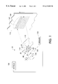
- FIG. 1 is a schematic perspective view, partially broken away, of one exemplary ROS system embodiment embodying one example of the subject bow correction system, for small controlled deformation of the second fold mirror of the ROS in this example;
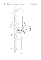
- FIG. 2 is a top view of the exemplary bow correction system of FIG. 1;
- FIG. 3 is a side view (partially broken off) of the exemplary bow correction system of FIGS. 1 and 2;
- FIG. 4 is a central cross-sectional end view of the exemplary bow correction system of FIGS. 1-3;
- FIG. 5 is a top view, partially broken away, of a partially different exemplary embodiment of a fine mirror deformation system, shown here for orthogonal axis bowing of the same mirror;
- FIG. 6 is a cross-sectional end view of the exemplary mirror deformation system of FIG. 5 .
- FIG. 1 there is shown one example of a printer raster output scanner (ROS) system 10 with one example of the subject bow correction system 20 (which system 20 is illustrated in enlarged detail in FIGS. 2 - 4 ).
- ROS printer raster output scanner
- a laser or lasers 104 generates one or more light beams which are modulated by a modulator 105 and swept by a rotating polygon faceted mirror 106 driven by a motor M, both under control of a controller 100 with an electronic image input.
- That scanning beam or beams may be reflected by a first mirror 110 to a second or final (and elongated) fold mirror 112 , which reflects the scanning beams onto the surface of a moving photoreceptor 118 , to image that photoreceptor 118 with closely spaced scan lines 122 .
- the scan lines 122 expose the photoreceptor 118 in image pixel patterns defined by the modulator 105 , to form developable and printable images in a well known manner.
- ROS systems tend to have undesired bowing in the scan lines 122 .
- One example of such an uncorrected bow 120 of the scan line 122 is illustrated (greatly exaggerated) in the dashed line 120 in FIG. 1 .
- the bow variation from one ROS imager to another ROS imager can be as high as 50 um or greater, and this is unacceptable for registration in a color machine with multiple imagers.
- the bow varies greatly from ROS to ROS due to optical and mechanical tolerances; therefore, an individual ROS bow correction technique is important to achieve registration. That is, an individual adjustment of an optical element of the ROS system.
- the ROS final fold mirror was determined to be the most desirable optical element compensator to correct for bow in ROS systems with two fold mirrors. A mechanical holder and adjustment mechanism for that mirror, as described herein, was designed to provide this bow correction adjustment, as shown in this embodiment example.
- FIGS. 2-4 show an exemplary such bow correction system and mechanism 20 . It will be apparent that various different constructions other than the example 20 disclosed below may be used to achieve the same function.
- the post-polygon second fold mirror 112 is placed inside a steel mirror mounting frame or carriage 23 , which holds this elongated mirror at its opposite ends (broken away in FIG. 1 for illustrative clarity).
- a steel yoke or C-clip 24 grips the approximate center of this elongated mirror 112 , contacting this mirror there at two locations (the top and bottom of the mirror).
- a first steel block 25 with a tapped and threaded hole 26 of one fine threading (e.g., M4.5 ⁇ 0.75 mm threading) is attached to the frame or carriage 23 .
- a differential screw 22 is inserted through the threaded hole 26 in the first (carriage) block 25 and also into the threaded hole 28 in the second (C-clip) block 27 .
- One end of the differential screw 22 has the same diameter and thread size as the hole 26 in the first block 25
- the other end of the screw 20 has the same diameter and thread size as the hole 28 in second block 27 .
- the mirror 112 is pulled toward the carriage by only about 50 um for each single screw turn.
- the mirror 112 thus bends very slightly in the fast scan plane (the X-plane), and the curvature of the mirror then resembles a parabolic surface.
- This small corrective curvature of the mirror 112 is illustrated (with large exaggeration) by the dashed line position thereof in FIG. 2 .
- the amount of applied mirror bend is proportional to the amount of bow correction required at the image plane.
- the special differential screw member 22 has two coaxial, but separate, and very slightly different pitch, screw thread surfaces 22 A and 22 B. These two slightly different pitch screw threads 22 A and 22 B effectively subtract from one another as the screw member 22 is rotated. Rotation of the screw member 22 thus moves its screw-connecting blocks 25 and 27 in opposite directions but by very small distances. Thus, applying an adjustment movement of only the very small difference between the two screw pitches to the bowing deflection of the connecting mirror 112 .
- very small mirror curvature adjustments of only, for example, plus or minus 5 or 10 um can be easily made by simple gross screw turn adjustments.
- a screwdriver rotation of an entire turn of the differential screw 22 can provide as little as 50 um of axial movement in this example.
- the bow correction mechanism 20 may desirably be initially assembled under tension with the mirror curved or bent by the maximum desired correction amount (e.g., about 150 um of initial mirror deformation from planar), which in this example equates to about 3 turns of the differential screw 22 . This tightens up and removes all “slack” or “backlash” in the system 20 . Then, for the bow correction adjustment, the differential screw may be turned back counter clockwise, while observing the bow pattern change on the PR 118 or and equivalent substitute factory test surface. That is, rotating the screw 22 to relax said initial relatively larger mirror curvature until the bow error has been reduced by lesser mirror curvature to an acceptable bowing range of only ⁇ 5 um to ⁇ 10 um.
- the maximum desired correction amount e.g., about 150 um of initial mirror deformation from planar
- the amount of acceptable corrected residual bow may vary from imager to imager from ⁇ 5 um to ⁇ 10 um.
- the final corrected bow shape on the PR may have a slight “W” (or “M”) profile within that allowable range, because the slightly deformed (curved) mirror 112 after its bow correction is not truly cylindrical and its radius varies, due to its slightly parabolic shape as corrected.
- the shape of the curved mirror 112 is not cylindrical here in this example 20 because the mirror 112 is being pulled only in its center.
- “W” shape bow profile is not a concern if the imagers are for different printers, or if all of the imagers for the same printer all have a similar corrected bow signature and the above bow matching specification from imager to imager is satisfied.
- additional such mirror deformation bow correction mechanisms can be provided using two yokes or C-clips, spaced equidistantly from the center of the mirror, if desired.
- This disclosed system 20 provides a sufficiently accurate method to correct for bow at the image plane (on the PR surface) without any difficulty. This adjustment can thus be easily performed relatively non-critically in manufacturing.
- the components that constitute the assembly are easily fabricated (easily machined and sheet metal parts).
- This simple bow correction system 20 has enough range and resolution to have the capability of correcting bow within at least ⁇ 10 um. Furthermore, the bow correction can be matched from imager to imager of the same type to within at least ⁇ 5 um.
- FIGS. 5 and 6 show another, generally similar, mirror deflection system 50 using the same differential screw 22 for mirror 112 or other mirror deformation (bowing) on the opposite or orthogonal axis to the system 20 of FIGS. 1-4.
- a rigid supporting frame member 52 which may be fastened to the back of the mirror glass, extends axially along the back of the mirror 112 , centrally thereof, as shown.
- a slightly different C-clamp 54 grips the top and bottom edges of the mirror. In this example, near both ends of the mirror as well as centrally.
- This C-clamp 54 has a mating threaded screw hole 55 block connection to one of the two sets of screw threads 22 A on the screw 22 .
- the other screw threads 22 B on the screw 22 are threaded into a mating screw hole 56 in another rigid frame member 57 (which may connect with frame member 52 ).
- rotation of the differential screw 22 pulls with the C-clamp 54 the top and bottom of the mirror 112 relative to the central axis of the mirror which is held in position by its rigid support 52 , thus bowing the mirror 112 as illustrated by the exaggerated dashed lines in FIG. 6 .
- Opposite screw 22 rotation would provide opposite direction mirror bowing.
Landscapes
- Physics & Mathematics (AREA)
- General Physics & Mathematics (AREA)
- Optics & Photonics (AREA)
- Mechanical Optical Scanning Systems (AREA)
- Laser Beam Printer (AREA)
Abstract
Description
Claims (1)
Priority Applications (1)
| Application Number | Priority Date | Filing Date | Title |
|---|---|---|---|
| US09/458,150 US6219082B1 (en) | 1999-12-09 | 1999-12-09 | Printer raster output scanning system with differential screw micron level bow correction |
Applications Claiming Priority (1)
| Application Number | Priority Date | Filing Date | Title |
|---|---|---|---|
| US09/458,150 US6219082B1 (en) | 1999-12-09 | 1999-12-09 | Printer raster output scanning system with differential screw micron level bow correction |
Publications (1)
| Publication Number | Publication Date |
|---|---|
| US6219082B1 true US6219082B1 (en) | 2001-04-17 |
Family
ID=23819576
Family Applications (1)
| Application Number | Title | Priority Date | Filing Date |
|---|---|---|---|
| US09/458,150 Expired - Lifetime US6219082B1 (en) | 1999-12-09 | 1999-12-09 | Printer raster output scanning system with differential screw micron level bow correction |
Country Status (1)
| Country | Link |
|---|---|
| US (1) | US6219082B1 (en) |
Cited By (14)
| Publication number | Priority date | Publication date | Assignee | Title |
|---|---|---|---|---|
| US6394568B1 (en) * | 2000-01-18 | 2002-05-28 | Hewlett-Packard Company | Structure for adjusting printhead to platen spacing in a printer and related methods |
| EP1308707A1 (en) * | 2001-11-05 | 2003-05-07 | CENTRE NATIONAL D'ETUDES SPATIALES (C.N.E.S.) Etablissement public, scientifique et | Device with a turning platform for supporting and orienting a charge |
| US20030142380A1 (en) * | 2001-11-09 | 2003-07-31 | Pentax Corporation | Scanning optical system |
| US20040169715A1 (en) * | 2003-02-27 | 2004-09-02 | Xerox Corporation | Bow adjustment in an optical scanning system by adjusting the curvature of a cylindrical mirror |
| US20050052761A1 (en) * | 2003-09-04 | 2005-03-10 | Bennett Optical Research, Inc. | Active/adaptive actuator design of an adaptive optic mirror |
| US20060103906A1 (en) * | 2004-07-29 | 2006-05-18 | Canon Kabushiki Kaisha | Optical scanning apparatus having scanning line curvature correcting mechanism |
| US7311408B2 (en) * | 2006-02-10 | 2007-12-25 | Kun-Ta Lee | Adjustable rear view mirror structure |
| CN100454082C (en) * | 2004-07-29 | 2009-01-21 | 佳能株式会社 | Optical scanning device with scanning line bending correction mechanism |
| CN1885898B (en) * | 2005-06-22 | 2010-07-28 | 宇东电浆科技有限公司 | Machine core structure of scanner |
| US20110279624A1 (en) * | 2010-05-14 | 2011-11-17 | Atsushi Ueda | Optical scanner and image forming apparatus |
| US9223131B2 (en) * | 2014-05-16 | 2015-12-29 | Kyocera Document Solutions Inc | Optical scanning device and image forming apparatus including the same |
| US20170010560A1 (en) * | 2015-07-06 | 2017-01-12 | Kabushiki Kaisha Toshiba | Image forming apparatus |
| EP3463918A4 (en) * | 2016-05-24 | 2020-01-15 | Electronics for Imaging, Inc. | ELASTIC BENDING MECHANISM FOR TWO-WAY ADJUSTMENT OF THE POSITION OF A PRINTHEAD |
| CN111487742A (en) * | 2020-05-29 | 2020-08-04 | 中国科学院长春光学精密机械与物理研究所 | A differential heavy-duty fine-tuning mechanism |
Citations (2)
| Publication number | Priority date | Publication date | Assignee | Title |
|---|---|---|---|---|
| US5084715A (en) * | 1989-02-02 | 1992-01-28 | Ricoh Company, Ltd. | Light beam scanning apparatus |
| US5596404A (en) * | 1994-12-30 | 1997-01-21 | Albion Instruments, Inc. | Raman gas analysis system with flexible web and differential thread for precision optical alignment |
-
1999
- 1999-12-09 US US09/458,150 patent/US6219082B1/en not_active Expired - Lifetime
Patent Citations (2)
| Publication number | Priority date | Publication date | Assignee | Title |
|---|---|---|---|---|
| US5084715A (en) * | 1989-02-02 | 1992-01-28 | Ricoh Company, Ltd. | Light beam scanning apparatus |
| US5596404A (en) * | 1994-12-30 | 1997-01-21 | Albion Instruments, Inc. | Raman gas analysis system with flexible web and differential thread for precision optical alignment |
Cited By (22)
| Publication number | Priority date | Publication date | Assignee | Title |
|---|---|---|---|---|
| US6394568B1 (en) * | 2000-01-18 | 2002-05-28 | Hewlett-Packard Company | Structure for adjusting printhead to platen spacing in a printer and related methods |
| EP1308707A1 (en) * | 2001-11-05 | 2003-05-07 | CENTRE NATIONAL D'ETUDES SPATIALES (C.N.E.S.) Etablissement public, scientifique et | Device with a turning platform for supporting and orienting a charge |
| FR2831958A1 (en) * | 2001-11-05 | 2003-05-09 | Centre Nat Etd Spatiales | TURNTABLE DEVICE FOR SUPPORTING AND ORIENTING A LOAD |
| US20030142380A1 (en) * | 2001-11-09 | 2003-07-31 | Pentax Corporation | Scanning optical system |
| US6731419B2 (en) * | 2001-11-09 | 2004-05-04 | Pentax Corporation | Scanning optical system |
| US6791595B1 (en) | 2003-02-27 | 2004-09-14 | Xerox Corporation | Bow adjustment in an optical scanning system by adjusting the curvature of a cylindrical mirror |
| US20040169715A1 (en) * | 2003-02-27 | 2004-09-02 | Xerox Corporation | Bow adjustment in an optical scanning system by adjusting the curvature of a cylindrical mirror |
| US20050052761A1 (en) * | 2003-09-04 | 2005-03-10 | Bennett Optical Research, Inc. | Active/adaptive actuator design of an adaptive optic mirror |
| US6886951B2 (en) * | 2003-09-04 | 2005-05-03 | Bennett Optical Research, Inc. | Active/adaptive actuator design of an adaptive optic mirror |
| US20060103906A1 (en) * | 2004-07-29 | 2006-05-18 | Canon Kabushiki Kaisha | Optical scanning apparatus having scanning line curvature correcting mechanism |
| US7453487B2 (en) * | 2004-07-29 | 2008-11-18 | Canon Kabushiki Kaisha | Optical scanning apparatus having scanning line curvature correcting mechanism with sliding pressure point along a longitudinal direction of the optical element |
| CN100454082C (en) * | 2004-07-29 | 2009-01-21 | 佳能株式会社 | Optical scanning device with scanning line bending correction mechanism |
| CN1885898B (en) * | 2005-06-22 | 2010-07-28 | 宇东电浆科技有限公司 | Machine core structure of scanner |
| US7311408B2 (en) * | 2006-02-10 | 2007-12-25 | Kun-Ta Lee | Adjustable rear view mirror structure |
| US20110279624A1 (en) * | 2010-05-14 | 2011-11-17 | Atsushi Ueda | Optical scanner and image forming apparatus |
| US8553062B2 (en) * | 2010-05-14 | 2013-10-08 | Sharp Kabushiki Kaisha | Optical scanner and image forming apparatus |
| US9223131B2 (en) * | 2014-05-16 | 2015-12-29 | Kyocera Document Solutions Inc | Optical scanning device and image forming apparatus including the same |
| US20170010560A1 (en) * | 2015-07-06 | 2017-01-12 | Kabushiki Kaisha Toshiba | Image forming apparatus |
| US9568852B2 (en) * | 2015-07-06 | 2017-02-14 | Kabushiki Kaisha Toshiba | Image forming apparatus with mirror curving adjustment unit |
| US9703227B2 (en) * | 2015-07-06 | 2017-07-11 | Kabushiki Kaisha Toshiba | Image forming apparatus with mirror adjustment unit |
| EP3463918A4 (en) * | 2016-05-24 | 2020-01-15 | Electronics for Imaging, Inc. | ELASTIC BENDING MECHANISM FOR TWO-WAY ADJUSTMENT OF THE POSITION OF A PRINTHEAD |
| CN111487742A (en) * | 2020-05-29 | 2020-08-04 | 中国科学院长春光学精密机械与物理研究所 | A differential heavy-duty fine-tuning mechanism |
Similar Documents
| Publication | Publication Date | Title |
|---|---|---|
| US6219082B1 (en) | Printer raster output scanning system with differential screw micron level bow correction | |
| US6771300B2 (en) | Multi-beam scanning device | |
| US20020001118A1 (en) | Multi-beam light source device and multi-beam scanning apparatus using the same | |
| JP2007240590A (en) | Optical scanning apparatus and image forming apparatus | |
| JP3569412B2 (en) | Optical scanning device for multicolor image forming apparatus | |
| US5592324A (en) | Cylindrical inner surface scanner and imaging control method in cylindrical inner surface scanner | |
| JP3111515B2 (en) | Scanning optical device | |
| KR100384431B1 (en) | Multi-beam scanning optical system and image forming apparatus using the same | |
| JP2001228427A (en) | Optical scanner and image forming device | |
| US6963433B2 (en) | Multibeam scanning optical device and image forming apparatus using the same | |
| JP2004287380A (en) | Optical scanning device, scanning line correction method, scanning line correction control method, image forming apparatus, and image forming method | |
| EP0631166B1 (en) | Ros bow compensation | |
| JP5895451B2 (en) | Optical scanning apparatus and image forming apparatus | |
| US5970597A (en) | Precision assembly technique using alignment fixture and the resulting assembly | |
| JP2001117040A (en) | Optical scanner and image forming device | |
| JP2007065500A (en) | Optical element holding mechanism, optical scanning apparatus and image forming apparatus having the same | |
| US6429891B1 (en) | Printhead mounting apparatus providing adjustment to effect printhead skew correction | |
| US5084715A (en) | Light beam scanning apparatus | |
| JP2007171626A (en) | Optical scanning device and image forming device | |
| JP4668606B2 (en) | Tandem laser scanning unit | |
| CN101105666B (en) | Image forming apparatus | |
| JP2004301971A (en) | Optical scanner | |
| JP2000258715A (en) | Tandem scanning optical device | |
| JPH1039194A (en) | Deflection mirror adjustment device | |
| KR960009042Y1 (en) | Adjusting device of laser beam for an optical instrument |
Legal Events
| Date | Code | Title | Description |
|---|---|---|---|
| AS | Assignment |
Owner name: XEROX CORPORATION, CONNECTICUT Free format text: ASSIGNMENT OF ASSIGNORS INTEREST;ASSIGNORS:RUMSEY, KAREN M.;GEORGE, CLIFFORD L.;WILLIAMS, ANTONIO L.;AND OTHERS;REEL/FRAME:010707/0103;SIGNING DATES FROM 20000214 TO 20000224 |
|
| STCF | Information on status: patent grant |
Free format text: PATENTED CASE |
|
| AS | Assignment |
Owner name: BANK ONE, NA, AS ADMINISTRATIVE AGENT, ILLINOIS Free format text: SECURITY INTEREST;ASSIGNOR:XEROX CORPORATION;REEL/FRAME:013153/0001 Effective date: 20020621 |
|
| AS | Assignment |
Owner name: JPMORGAN CHASE BANK, AS COLLATERAL AGENT, TEXAS Free format text: SECURITY AGREEMENT;ASSIGNOR:XEROX CORPORATION;REEL/FRAME:015134/0476 Effective date: 20030625 Owner name: JPMORGAN CHASE BANK, AS COLLATERAL AGENT,TEXAS Free format text: SECURITY AGREEMENT;ASSIGNOR:XEROX CORPORATION;REEL/FRAME:015134/0476 Effective date: 20030625 |
|
| FPAY | Fee payment |
Year of fee payment: 4 |
|
| FPAY | Fee payment |
Year of fee payment: 8 |
|
| FPAY | Fee payment |
Year of fee payment: 12 |
|
| AS | Assignment |
Owner name: XEROX CORPORATION, NEW YORK Free format text: RELEASE BY SECURED PARTY;ASSIGNOR:JPMORGAN CHASE BANK, N.A.;REEL/FRAME:034717/0470 Effective date: 20061204 Owner name: XEROX CORPORATION, NEW YORK Free format text: RELEASE BY SECURED PARTY;ASSIGNOR:BANK ONE, NA;REEL/FRAME:034716/0024 Effective date: 20030625 |
|
| AS | Assignment |
Owner name: XEROX CORPORATION, CONNECTICUT Free format text: RELEASE BY SECURED PARTY;ASSIGNOR:JPMORGAN CHASE BANK, N.A. AS SUCCESSOR-IN-INTEREST ADMINISTRATIVE AGENT AND COLLATERAL AGENT TO JPMORGAN CHASE BANK;REEL/FRAME:066728/0193 Effective date: 20220822 |