US6205742B1 - Method and apparatus for manufacturing and installing roof tiles - Google Patents
Method and apparatus for manufacturing and installing roof tiles Download PDFInfo
- Publication number
- US6205742B1 US6205742B1 US08/711,042 US71104296A US6205742B1 US 6205742 B1 US6205742 B1 US 6205742B1 US 71104296 A US71104296 A US 71104296A US 6205742 B1 US6205742 B1 US 6205742B1
- Authority
- US
- United States
- Prior art keywords
- tile
- tiles
- indicia
- cutting
- laying
- Prior art date
- Legal status (The legal status is an assumption and is not a legal conclusion. Google has not performed a legal analysis and makes no representation as to the accuracy of the status listed.)
- Expired - Fee Related
Links
Images


Classifications
-
- B—PERFORMING OPERATIONS; TRANSPORTING
- B28—WORKING CEMENT, CLAY, OR STONE
- B28B—SHAPING CLAY OR OTHER CERAMIC COMPOSITIONS; SHAPING SLAG; SHAPING MIXTURES CONTAINING CEMENTITIOUS MATERIAL, e.g. PLASTER
- B28B5/00—Producing shaped articles from the material in moulds or on moulding surfaces, carried or formed by, in, or on conveyors irrespective of the manner of shaping
- B28B5/10—Producing shaped articles from the material in moulds or on moulding surfaces, carried or formed by, in, or on conveyors irrespective of the manner of shaping in moulds carried on the circumference of a rotating drum
- B28B5/12—Producing shaped articles from the material in moulds or on moulding surfaces, carried or formed by, in, or on conveyors irrespective of the manner of shaping in moulds carried on the circumference of a rotating drum intermittently rotated
-
- B—PERFORMING OPERATIONS; TRANSPORTING
- B28—WORKING CEMENT, CLAY, OR STONE
- B28B—SHAPING CLAY OR OTHER CERAMIC COMPOSITIONS; SHAPING SLAG; SHAPING MIXTURES CONTAINING CEMENTITIOUS MATERIAL, e.g. PLASTER
- B28B7/00—Moulds; Cores; Mandrels
- B28B7/0064—Moulds characterised by special surfaces for producing a desired surface of a moulded article, e.g. profiled or polished moulding surfaces
- B28B7/007—Moulds characterised by special surfaces for producing a desired surface of a moulded article, e.g. profiled or polished moulding surfaces with moulding surfaces simulating natural effets, e.g. wood or stone
-
- E—FIXED CONSTRUCTIONS
- E04—BUILDING
- E04D—ROOF COVERINGS; SKY-LIGHTS; GUTTERS; ROOF-WORKING TOOLS
- E04D1/00—Roof covering by making use of tiles, slates, shingles, or other small roofing elements
- E04D1/02—Grooved or vaulted roofing elements
- E04D1/04—Grooved or vaulted roofing elements of ceramics, glass or concrete, with or without reinforcement
-
- E—FIXED CONSTRUCTIONS
- E04—BUILDING
- E04D—ROOF COVERINGS; SKY-LIGHTS; GUTTERS; ROOF-WORKING TOOLS
- E04D1/00—Roof covering by making use of tiles, slates, shingles, or other small roofing elements
- E04D1/29—Means for connecting or fastening adjacent roofing elements
- E04D1/2907—Means for connecting or fastening adjacent roofing elements by interfitted sections
- E04D1/2914—Means for connecting or fastening adjacent roofing elements by interfitted sections having fastening means or anchors at juncture of adjacent roofing elements
- E04D1/2916—Means for connecting or fastening adjacent roofing elements by interfitted sections having fastening means or anchors at juncture of adjacent roofing elements the fastening means taking hold directly on adjacent elements of the same row
Definitions
- This invention relates in general to roofing, and particularly relates to the use of light weight yet structurally sound clay roof tile to simulate wood shake roofing, in a stacking configuration which includes cutting indicia to facilitate the stacking of the tile in a manner which discourages pattern repetition.
- the material When done with concrete, the material is typically cast in a lower mold only.
- the only contours possible on the upper surface are those created by the linear planing off of the wet material immediately after pouring, which can be limiting.
- Metal pressed products tend to be limited to shapes with identical contours on both top and bottom surfaces.
- the present invention overcomes deficiencies of the prior art by providing an improved tile, and method and apparatus for providing same, which includes improved structural capabilities, yet simulates a wood shake construction.
- FIG. 1 is a pictorial view of a rotatable mold 10 , including multiple tile-shaped cavities 11 A, 11 B for receiving clay.
- FIG. 2 is an illustrative end view of a mold 10 such as shown in FIG. 1, viewed along its axis of rotation and illustrating its interaction with a reciprocating top mold member 14 , as it works with the base mold member 10 in converting clay bats 13 into tile forms which, upon further processing, will provide tile according to the present invention.
- FIGS. 3 a and 3 b are pictorial views of “sister” tile configurations 20 A, 20 B, respectively.
- FIG. 4 is a side view illustrating the overlapping nature of the tiles 20 when they are installed atop a supporting surface 42 , and secured thereon by nails or other suitable fasteners 41 .
- FIG. 5 is a top plan illustrative view of a “generic” tile 20 with cutting indicia molded therein which can be used to guide the installer to create a predetermined yet typically imperceptible stacking pattern.
- a cut along dotted line 50 would be following the cut mark “5”.
- FIG. 5 also shows the provision of three nail holes 19 .
- FIG. 6 is an illustrative view illustrating the stacking configuration according to the present invention, which although having a repetitive pattern, is substantially imperceptible to the typical human eye.
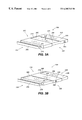
- FIG. 7 is a top plan view of a tile configuration 20 A according to the present invention.
- FIG. 8 is a cross-sectional view of the tile in FIG. 7, taken along line 8 — 8 .
- FIG. 9 is a top plan view of a tile 20 b according to the present invention.
- FIG. 10 is a cross-sectional view of the tile of FIG. 9, taken along line 10 — 10 .
- FIGS. 1 and 2 illustrate the general manufacturing process for providing tiles 20 according to the present invention, that being the use of rotating mold 10 , which accepts clay bats 13 and forms them into tile shapes such as shown in FIGS. 3A and 3B. After being dried and kiln fired, these tiles can be installed in an overlapping manner as shown in FIG. 4 atop an inclined support surface such as 42 . As shown in FIG. 5, “cut marks” or other suitable indicia are molded into the clay shapes such that, upon suitable cutting by a installer (not shown), they can be installed in the configuration such as shown in FIG. 6 .
- FIGS. 1 and 2 combine to illustrate the general concept according to the present invention of manufacturing tiles according to the present invention, by molding raw unmolded clay into two similar tile forms suitable for oven firing.
- Clay with a moisture content sufficient to provide adequate plasticity (18-22% has been found acceptable) is extruded from a pugmill/extrusion machine in a column (not shown). As may be understood, the extrusion process evacuates substantially all of the air from the clay mixture to discourage delamination. The column is then cut into short lengths to create the blanks or “bats” 13 for pressing.
- the press structure includes a rotatable drum 10 having a hexagonal cross-section and defining six outwardly-directed drum faces. Two (lower) molds are provided in on each drum face, totaling 12 molds. To provide an aesthetically pleasing variation on the installed appearance of the tiles (discussed in detail below), one “A” and one “B” mold cavity 11 A, 11 B is provided on each face. The net result is a 50—50 mix of the two profiles in production.
- the clay bats enter the press and are deposited on the lower molds when the molds are in the 10 o'clock position.
- the drum 10 is configured to rotate about a substantially horizontal axis, such that upon drum rotation the bats 13 are moved into the 12 o'clock position, where the top mold member 14 comes down and presses the bats into the shape of the tile, and then withdraws upwardly.
- the drum then rotates the pressed tile forms 20 to the “2 o'clock” position, where a vacuum picker (not shown) such as known in the art moves in and simultaneously trims off the excess clay around the edges of the tiles and punches nail holes as needed, It removes the tiles from the drum face and deposits them on drying trays (not shown) that are passed under the picker on a synchronized conveyor.
- a vacuum picker (not shown) such as known in the art moves in and simultaneously trims off the excess clay around the edges of the tiles and punches nail holes as needed, It removes the tiles from the drum face and deposits them on drying trays (not shown) that are passed under the picker on a synchronized conveyor.
- the wet tiles, on their individual dryer trays, are then sent through a dryer where the moisture content is reduced to less than 1%.
- the dry “greenware” is then transported to the kiln for firing.
- the vitrified tiles, in the forms shown in FIGS. 3A and 3B, are then placed directly into their shipping pallets.
- the tiles according to the present invention are produced in a manner such as to provide a 50—50 production of two “sister” tile configurations, referenced at this point forward as 20 A and 20 B configurations.
- Each of these configurations is interchangeable within a stacking configuration described in further detail; however, the decorative upper surfaces are somewhat different in appearance. If the tiles are installed randomly, perceptibly repetitive patterns will be discouraged, especially if the tiles are installed as discussed below.
- FIGS. 3A and 3B each of which illustrates a single tile 20 A, 20 B, respectively.
- the upwardly directed face, as well as the butts of each of the tiles contain abrupt changes in elevation and setback to simulate three (3) individual pieces of wood shake. These changes create the desired shadowing and appearance to simulate wood shakes.
- tile 20 A includes a center section 22 A, a “left” (as viewed from the butt end) section 23 A, a right section 24 A, and a sidewardly-extending engagement member 25 A, which extends to the left of member 23 A, and defines a channel 26 A and includes an upwardly-directed ledge portion 27 A.
- the tile 20 A includes a “head” end 31 A, a “butt” end 32 A, a left edge 33 , and a right edge 34 .
- the sections 22 A, 23 A and 24 A all include simulated woodgrain designs 28 A, at their upper surfaces and at their butt edges, which gives each tile the appearance of three side-by-side conventional wood shake members, which in practice tend to have their upper surfaces at varying heights due to differences in shake thicknesses and other natural variances.
- the center member 22 A is somewhat lower than its two adjacent members 23 A, 24 A, and includes an inclined portion 29 B.
- the center portion 22 A does not extend towards the “butt” end of the tile as much as its two adjacent members 23 A, 24 A, giving a “set-back” appearance, simulating installed wood shakes.
- the tile 20 A also includes a downwardly-directed side engagement member 37 A.
- the tile 20 B shown in that figure includes a center portion 22 B, a left portion 23 B, a right portion 24 B, a sidewardly-extending upwardly-directed engagement member 25 B (defining a channel 26 B and including an upwardly-directed engagement ledge 27 A).
- the tile 20 B includes a head end 31 B, a “butt” end 32 B, a left edge 33 B, and a right edge 34 B.
- tile 20 B includes the three members 22 B, 23 B, and 24 B, which simulate three adjacent wood shakes.
- Inclined face portions 29 B (two shown in FIG. 3B) compensate for the fact that the left section 23 B, and the right section 24 B each slope slightly towards the relatively higher center portion 22 B.
- tile 20 B does not have an uniform “butt” edge, instead its section 22 B extends outwardly somewhat relatively to its two adjacent sections 23 B, 24 B.
- tile 20 B likewise include a sidewardly-extending downwardly-directed engagement member 37 B, which includes a downwardly-directed drip ridge 39 B, which extends the length of the member 37 B. It should be noted that tile 20 A likewise has a drip ridge, although it is not numbered in FIG. 8 .
- the sidewardly-extending interlocking members 25 A, 25 B, of the tile members allow for the interlocking of laterally adjacent tile members to form a horizontal course as discussed in detail below.
- the interlocking members 25 A, 25 B, of the tiles 20 A, 20 B, respectively are “set back” a distance “SB” (see FIGS. 7 and 9) from the butt ends of their adjacent sections 23 A, 23 B, respectively.
- This provides an improvement over the known prior art, as the “interlocking” interface illustrated in FIG. 8 (between the solid line downwardly-directed interlocking member 37 A and the dotted-line member 35 A) is “hidden” somewhat by the overhanging nature of the downwardly-directed interlocking member 37 A.
- this tile is light in weight, as defined by the requirement of having an installed weight in the order of less than 6 pounds per square foot.
- the bottom surfaces of the tiles are not solid like some prior art configurations, but instead include the use of strategically-placed structural ribs and a substantially consistent shelf thickness to provide a lightweight yet structurally sound tile configuration.
- FIGS. 7-10 provides some further details regarding the configuration of the two top members 20 A, 20 B.
- a plurality of structural support ribs extend downwardly from what could be referred to as the main body or “shelf” of each of the tiles.
- Four of these structural support ribs 35 are substantially coparallel and are located to correspond with the highest points on the top of the tile.
- the provision of structural rib locations within the tile at locations immediately beneath the topmost “peaks” extending from top surface of the tiles provides superior strength when subjecting the tile to flexural strength testing or actual field conditions, where the tiles must support foot traffic.
- the remaining rib is a “butt” rib 36 which extends along the butt edge of each of the tiles.
- the butt ribs includes a number of “jogs” which correspond to the jogged nature of the butts of the tiles.
- the tiles 20 A, 20 B are typically installed horizontally in interlocked courses, with each horizontal course overlapping the one immediately below it.
- the overlap is typically three (3) inches, although other overlap lengths are contemplated without departing from the spirit and scope of the present invention.
- Each of the tiles 20 A, 20 B is designed so that the rear edge of the upper surface is both level and the highest elevation of the tile. This provides a level resting surface 21 ( 21 A for tile 20 A and 21 B for tile 20 B) for the structural support ribs of the overlapping tiles, discouraging unwanted rocking motion under load and minimizing any possible fulcrum points that might promote breakage.
- the main “body” or “shelf” of the tile members includes a substantially consistent thickness.
- the side portions 23 B, 24 B of the tile 20 B are of a substantially consistent thickness, yet taper towards the center of the tile, in order to divert as much water as possible from the joints that occur between adjacent tiles.
- FIG. 5 generally illustrates the use of indicia placed on the tiles in the form of recessed slits extending a distance from the head end of the tiles. As discussed in detail later, such indicia facilitates perceptibly random lateral orientation of the horizontal courses relative to each other.
- the present invention provides a plurality of numbered marks (eight in one preferred embodiment) on the upper edge of the tile to serve as a cutting guide just prior to the installation process. Although these marks (known generically as “indicia”) are placed upon the top surface of the tile, they are concealed during the installation process by the overlap as shown in FIG. 4 .
- FIGS. 4 and 6 combine to illustrate the tile installation or “stacking” process according to the present invention.
- the tile are overlapped as discussed above, and attached to a supporting surface (such as plywood) by nails or other suitable fasteners.
- a course 100 of tiles 20 begins with a full uncut tile 20 with its uncut right edge (corresponding to mark #1) aligned along the alignment edge line 61 .
- the second course 200 is started with a tile cut on mark #2 and laid with its cut edge along the alignment edge line 61 , the third course 300 with a tile cut on mark #3 and laid with its cut edge along the alignment edge line 61 , and so on through the eighth course 800 . Then the sequence is repeated.
- the numbers are placed to the left of the cutting mark so that they can be referenced when the installer returns to start the next course. This provides a predetermined yet random appearing pattern without the need of any printed diagram, measuring tools or the possibility of accidental unwanted patterns.
- One important feature of the invention is the provision of all the cutting marks to the right of the two leftmost coparallel structural ribs. This assures that at least two ribs will remain after cutting is complete, which will be recognized as advantageous in that stable tile placement is encouraged.
- the present invention overcomes deficiencies in the prior art by providing a tile which can be produced in mass quantities, yet has the appearance of traditional wood shakes with the structural properties of fired clay.
- the present invention also provides an improved stacking configuration which allows for the use of a predetermined stacking pattern which nevertheless results in a stacked configuration which appears random to the typical observer.
Abstract
Description
Claims (3)
Priority Applications (2)
| Application Number | Priority Date | Filing Date | Title |
|---|---|---|---|
| US08/711,042 US6205742B1 (en) | 1996-09-10 | 1996-09-10 | Method and apparatus for manufacturing and installing roof tiles |
| US09/087,555 US6105328A (en) | 1996-09-10 | 1998-05-29 | Method and apparatus for manufacturing and installing roof tiles having improved strength and stacking features |
Applications Claiming Priority (1)
| Application Number | Priority Date | Filing Date | Title |
|---|---|---|---|
| US08/711,042 US6205742B1 (en) | 1996-09-10 | 1996-09-10 | Method and apparatus for manufacturing and installing roof tiles |
Related Parent Applications (1)
| Application Number | Title | Priority Date | Filing Date |
|---|---|---|---|
| US29072246 Continuation-In-Part | 1997-06-10 |
Related Child Applications (1)
| Application Number | Title | Priority Date | Filing Date |
|---|---|---|---|
| US09/087,555 Continuation-In-Part US6105328A (en) | 1996-09-10 | 1998-05-29 | Method and apparatus for manufacturing and installing roof tiles having improved strength and stacking features |
Publications (1)
| Publication Number | Publication Date |
|---|---|
| US6205742B1 true US6205742B1 (en) | 2001-03-27 |
Family
ID=24856568
Family Applications (1)
| Application Number | Title | Priority Date | Filing Date |
|---|---|---|---|
| US08/711,042 Expired - Fee Related US6205742B1 (en) | 1996-09-10 | 1996-09-10 | Method and apparatus for manufacturing and installing roof tiles |
Country Status (1)
| Country | Link |
|---|---|
| US (1) | US6205742B1 (en) |
Cited By (10)
| Publication number | Priority date | Publication date | Assignee | Title |
|---|---|---|---|---|
| US6625939B1 (en) * | 1998-08-18 | 2003-09-30 | Certainteed Corporation | Building panel as a covering for building surfaces and method of applying |
| US6679011B2 (en) * | 1994-05-13 | 2004-01-20 | Certainteed Corporation | Building panel as a covering for building surfaces and method of applying |
| US20050257477A1 (en) * | 2004-05-20 | 2005-11-24 | United States Tile Company | Roofing system and roofing tile |
| US20060026908A1 (en) * | 2004-08-05 | 2006-02-09 | Gregori Werner K H | Simulated wood shingles with multiple alignment features |
| US20080110122A1 (en) * | 2006-11-09 | 2008-05-15 | Lehane James J | Suspended ceiling with measurement indicia |
| US20090193746A1 (en) * | 2008-01-29 | 2009-08-06 | Ludowici Roof Tile | 2/3rds width flat interlocking tiles |
| US8122649B2 (en) | 2008-04-07 | 2012-02-28 | Ludowici Roof Tile | Interlocking tiles employing adjustable rain lock |
| US9404271B1 (en) * | 2014-09-23 | 2016-08-02 | Gerald Sadleir | System and method for creating concrete designs |
| CN107447926A (en) * | 2017-08-02 | 2017-12-08 | 江苏特福特建材有限公司 | A kind of wood grain is without keel watt and its production method |
| US20180209149A1 (en) * | 2016-01-25 | 2018-07-26 | Spray Tech Industries, LLC | Roofing systems and methods |
Citations (76)
| Publication number | Priority date | Publication date | Assignee | Title |
|---|---|---|---|---|
| DE93888C (en) | ||||
| US34586A (en) | 1862-03-04 | Improvement in setting artificial teeth | ||
| US147061A (en) | 1874-02-03 | Improvement in roofing-tiles | ||
| US479442A (en) | 1892-07-26 | maryice | ||
| US491625A (en) | 1893-02-14 | Carl wilhelm emil wutke | ||
| CA70225A (en) | 1900-04-21 | 1901-02-12 | Amedee A. Rochereau | Process of reproducing originals in colours |
| US1427968A (en) | 1921-04-15 | 1922-09-05 | Oscar A Pedersen | Roofing tile |
| US1454070A (en) | 1921-03-31 | 1923-05-08 | Openshaw Fred | Self-locking wireless molded roofing |
| GB416649A (en) | 1934-05-11 | 1934-09-18 | Owen Arthur Aisher | Improvements in or relating to roofing tiles |
| US1993086A (en) | 1929-10-28 | 1935-03-05 | Asphalt Process Corp | Roofing |
| GB438969A (en) | 1934-05-31 | 1935-11-27 | Douglas Cunningham | Improvement relating to gloves |
| US2171010A (en) * | 1938-04-15 | 1939-08-29 | United States Gypsum Co | Random thatch roof construction |
| US2340038A (en) | 1942-05-28 | 1944-01-25 | Keasbey & Mattison Company | Roofing and shingle therefor |
| US2430200A (en) | 1944-11-18 | 1947-11-04 | Nina Mae Wilson | Lock joint |
| US2510416A (en) | 1947-01-07 | 1950-06-06 | Charles N Pretty | Roofing tile |
| US2624298A (en) | 1951-09-04 | 1953-01-06 | Farren Roy | Tile roof structure |
| FR1259641A (en) | 1960-05-20 | 1961-04-28 | Tile, roofing made with tiles similar to this one or similar, tool for making this roofing or similar | |
| GB995692A (en) | 1963-07-12 | 1965-06-23 | Norman Vernon Imp Ers Ltd | Bracket |
| US3267823A (en) | 1963-06-10 | 1966-08-23 | John R Macrae | Stepping stones |
| US3440777A (en) | 1967-12-08 | 1969-04-29 | Otis M Martin | Shake strip assembly for roofing or siding |
| US3579940A (en) * | 1969-06-13 | 1971-05-25 | Stepan Chemical Co | Roofing tile |
| US3676969A (en) | 1970-04-03 | 1972-07-18 | Dan B Moore | Log type building unit |
| US3740914A (en) | 1969-11-06 | 1973-06-26 | J Diez | Tile for coating and decorating surfaces |
| US3775925A (en) * | 1970-12-02 | 1973-12-04 | Fujita Kenzo Kogyo Co Ltd | Roofing panel with drainage means |
| US3797179A (en) * | 1971-06-25 | 1974-03-19 | N Jackson | Mansard roof structure |
| US3873225A (en) | 1972-09-05 | 1975-03-25 | Karna Jakobsen | Paving stones |
| US3899855A (en) | 1972-02-11 | 1975-08-19 | Kanrich Nathaniel G | Peaked roof structure of polyurethane molded building panels with integral, bonded, low-density urethane insulation backing |
| US3927501A (en) * | 1975-01-15 | 1975-12-23 | Bird & Son | Random pattern shingle |
| US3977141A (en) * | 1974-10-23 | 1976-08-31 | Aluminum Company Of America | Metal shake or shingle panel and accessories |
| US4010592A (en) * | 1976-01-16 | 1977-03-08 | Roy Nixon | Template for and method of cutting composition shingles for rapid and scrap-free installation |
| US4034528A (en) | 1976-06-18 | 1977-07-12 | Aegean Industries, Inc. | Insulating vinyl siding |
| US4065899A (en) | 1973-01-10 | 1978-01-03 | Kirkhuff William J | Interlocking combination shingle and sheeting arrangement |
| US4107896A (en) * | 1976-09-24 | 1978-08-22 | Alfred Wetzel | Shingle-type wall panel |
| US4130974A (en) | 1977-02-16 | 1978-12-26 | Alcan Aluminum Corporation | Siding panels and the method of production |
| US4185939A (en) | 1977-07-18 | 1980-01-29 | Gunter Barth | Ground covering slab |
| GB2046808A (en) | 1979-04-11 | 1980-11-19 | Telling E F | Tiles |
| GB1586369A (en) | 1976-11-30 | 1981-03-18 | Ishikawa T | Panels for use in forming roofs and in cladding walls |
| US4279106A (en) * | 1979-11-05 | 1981-07-21 | Gleason Charles H | Roofing panel |
| GB2111550A (en) | 1981-10-20 | 1983-07-06 | Process Products Limited | Synthetic tile and process therefor |
| EP0088198A2 (en) | 1982-03-04 | 1983-09-14 | Jean-Claude Deppen | Method of constructing a covering for a building called "inverted roof", and prefabricated element for constructing such a covering |
| GB2123058A (en) | 1982-07-01 | 1984-01-25 | John Richard Blake | Roofing tiles |
| EP0115374A2 (en) | 1983-01-03 | 1984-08-08 | Polymer Building Products, Inc. | Roofing and siding members |
| US4468909A (en) * | 1982-05-03 | 1984-09-04 | Masonite Corporation | Building panel |
| US4506483A (en) | 1983-08-05 | 1985-03-26 | Roofblok Limited | Roof construction |
| US4527374A (en) * | 1980-01-03 | 1985-07-09 | Manville Service Corp. | Three-tab shingle with staggered butt edge feature |
| US4535579A (en) | 1983-08-05 | 1985-08-20 | Roofblok Limited | Roof ballast block |
| USD282288S (en) | 1983-02-17 | 1986-01-21 | Bates Leon H | Roof tile |
| US4574536A (en) | 1981-09-25 | 1986-03-11 | Oldcastle, Inc. | Roof tile |
| EP0175500A2 (en) | 1984-09-12 | 1986-03-26 | Redland Roof Tiles Limited | Improvements in roof tiles |
| USD283551S (en) | 1983-08-04 | 1986-04-22 | John Repasky | Paving block |
| GB2178773A (en) | 1985-08-02 | 1987-02-18 | Redland Roof Tiles Ltd | Improvements in roof tiles |
| EP0236585A1 (en) | 1986-03-14 | 1987-09-16 | Anjap N.V. | Composite roof covering plate comprising an insulating support layer and a covering layer suitable for walking on, and a roof covering formed by means of such a composite plate |
| US4738068A (en) | 1985-07-12 | 1988-04-19 | Fernando Mendez | Roof tile with channel |
| US4752520A (en) | 1986-12-15 | 1988-06-21 | Builder's Research And Development Corporation | Reinforced concrete tile and its method of manufacture |
| US4890432A (en) | 1987-03-25 | 1990-01-02 | Hopedelta Limited | Roof tile |
| US4899514A (en) | 1985-11-13 | 1990-02-13 | Brookhart Jr George C | Ballast block for roofing structures |
| US4932184A (en) | 1989-03-06 | 1990-06-12 | Gerard Tile, Inc. | Roofing panel |
| EP0375802A1 (en) | 1988-12-30 | 1990-07-04 | Les Tuiles Thermiques Du Quebec Inc. | Roof shingle |
| USD320091S (en) | 1987-12-24 | 1991-09-17 | Jean-Paul Paquette | Shingle |
| USD321942S (en) | 1987-07-27 | 1991-11-26 | Marley Tile A.G. | Tile |
| US5070671A (en) | 1988-01-18 | 1991-12-10 | Oldcastle, Inc. | Roof tiles |
| GB2245613A (en) | 1990-06-27 | 1992-01-08 | Gordon William John Taylor | Roofing or cladding panel |
| US5174092A (en) * | 1991-04-10 | 1992-12-29 | Naden Robert W | Steel tile roof |
| US5214895A (en) | 1988-01-18 | 1993-06-01 | Oldcastle, Inc. | Roof tiles |
| USD338541S (en) | 1990-09-06 | 1993-08-17 | Oldcastle, Inc. | Roof tile |
| US5249402A (en) * | 1991-04-09 | 1993-10-05 | Crick Dallas M | Decorative wall covering |
| US5268028A (en) | 1987-08-25 | 1993-12-07 | Oldcastle, Inc. | Lightweight concrete roof tiles and similar products |
| US5295339A (en) * | 1992-08-10 | 1994-03-22 | Manner Value Plastic, Inc. | Simulated individual self-venting overlapping plastic shake |
| USD347483S (en) | 1990-09-21 | 1994-05-31 | Monier Roof Tile Inc. | Concrete roof tile |
| US5395442A (en) | 1993-04-14 | 1995-03-07 | Boral Concrete Products, Inc. | Lightweight concrete roof tiles |
| USD356873S (en) | 1993-08-02 | 1995-03-28 | Oldcastle, Inc. | Roof tile |
| US5406766A (en) | 1993-07-29 | 1995-04-18 | Monier Roof Tile Inc. | Multi-color concrete tiles and method and apparatus for making same |
| US5490360A (en) | 1992-05-29 | 1996-02-13 | Oldcastle Inc. | Roofing elements |
| US5502940A (en) | 1992-08-21 | 1996-04-02 | Oldcastle, Inc. | Composite building element and methods of making and using the same |
| USD370539S (en) | 1994-04-22 | 1996-06-04 | Treat C Parker | Mold for cementitious roofing tile |
| US5603758A (en) | 1995-10-06 | 1997-02-18 | Boral Concrete Products, Inc. | Composition useful for lightweight roof tiles and method of producing said composition |
-
1996
- 1996-09-10 US US08/711,042 patent/US6205742B1/en not_active Expired - Fee Related
Patent Citations (77)
| Publication number | Priority date | Publication date | Assignee | Title |
|---|---|---|---|---|
| DE93888C (en) | ||||
| US34586A (en) | 1862-03-04 | Improvement in setting artificial teeth | ||
| US147061A (en) | 1874-02-03 | Improvement in roofing-tiles | ||
| US479442A (en) | 1892-07-26 | maryice | ||
| US491625A (en) | 1893-02-14 | Carl wilhelm emil wutke | ||
| CA70225A (en) | 1900-04-21 | 1901-02-12 | Amedee A. Rochereau | Process of reproducing originals in colours |
| US1454070A (en) | 1921-03-31 | 1923-05-08 | Openshaw Fred | Self-locking wireless molded roofing |
| US1427968A (en) | 1921-04-15 | 1922-09-05 | Oscar A Pedersen | Roofing tile |
| US1993086A (en) | 1929-10-28 | 1935-03-05 | Asphalt Process Corp | Roofing |
| GB416649A (en) | 1934-05-11 | 1934-09-18 | Owen Arthur Aisher | Improvements in or relating to roofing tiles |
| GB438969A (en) | 1934-05-31 | 1935-11-27 | Douglas Cunningham | Improvement relating to gloves |
| US2171010A (en) * | 1938-04-15 | 1939-08-29 | United States Gypsum Co | Random thatch roof construction |
| US2340038A (en) | 1942-05-28 | 1944-01-25 | Keasbey & Mattison Company | Roofing and shingle therefor |
| US2430200A (en) | 1944-11-18 | 1947-11-04 | Nina Mae Wilson | Lock joint |
| US2510416A (en) | 1947-01-07 | 1950-06-06 | Charles N Pretty | Roofing tile |
| US2624298A (en) | 1951-09-04 | 1953-01-06 | Farren Roy | Tile roof structure |
| FR1259641A (en) | 1960-05-20 | 1961-04-28 | Tile, roofing made with tiles similar to this one or similar, tool for making this roofing or similar | |
| US3267823A (en) | 1963-06-10 | 1966-08-23 | John R Macrae | Stepping stones |
| GB995692A (en) | 1963-07-12 | 1965-06-23 | Norman Vernon Imp Ers Ltd | Bracket |
| US3440777A (en) | 1967-12-08 | 1969-04-29 | Otis M Martin | Shake strip assembly for roofing or siding |
| US3579940A (en) * | 1969-06-13 | 1971-05-25 | Stepan Chemical Co | Roofing tile |
| US3740914A (en) | 1969-11-06 | 1973-06-26 | J Diez | Tile for coating and decorating surfaces |
| US3676969A (en) | 1970-04-03 | 1972-07-18 | Dan B Moore | Log type building unit |
| US3775925A (en) * | 1970-12-02 | 1973-12-04 | Fujita Kenzo Kogyo Co Ltd | Roofing panel with drainage means |
| US3797179A (en) * | 1971-06-25 | 1974-03-19 | N Jackson | Mansard roof structure |
| US3899855A (en) | 1972-02-11 | 1975-08-19 | Kanrich Nathaniel G | Peaked roof structure of polyurethane molded building panels with integral, bonded, low-density urethane insulation backing |
| US3873225A (en) | 1972-09-05 | 1975-03-25 | Karna Jakobsen | Paving stones |
| US4065899A (en) | 1973-01-10 | 1978-01-03 | Kirkhuff William J | Interlocking combination shingle and sheeting arrangement |
| US3977141A (en) * | 1974-10-23 | 1976-08-31 | Aluminum Company Of America | Metal shake or shingle panel and accessories |
| US3927501A (en) * | 1975-01-15 | 1975-12-23 | Bird & Son | Random pattern shingle |
| US4010592A (en) * | 1976-01-16 | 1977-03-08 | Roy Nixon | Template for and method of cutting composition shingles for rapid and scrap-free installation |
| US4034528A (en) | 1976-06-18 | 1977-07-12 | Aegean Industries, Inc. | Insulating vinyl siding |
| US4107896A (en) * | 1976-09-24 | 1978-08-22 | Alfred Wetzel | Shingle-type wall panel |
| GB1586369A (en) | 1976-11-30 | 1981-03-18 | Ishikawa T | Panels for use in forming roofs and in cladding walls |
| US4130974A (en) | 1977-02-16 | 1978-12-26 | Alcan Aluminum Corporation | Siding panels and the method of production |
| US4185939A (en) | 1977-07-18 | 1980-01-29 | Gunter Barth | Ground covering slab |
| GB2046808A (en) | 1979-04-11 | 1980-11-19 | Telling E F | Tiles |
| US4279106A (en) * | 1979-11-05 | 1981-07-21 | Gleason Charles H | Roofing panel |
| US4527374A (en) * | 1980-01-03 | 1985-07-09 | Manville Service Corp. | Three-tab shingle with staggered butt edge feature |
| US4574536A (en) | 1981-09-25 | 1986-03-11 | Oldcastle, Inc. | Roof tile |
| GB2111550A (en) | 1981-10-20 | 1983-07-06 | Process Products Limited | Synthetic tile and process therefor |
| EP0088198A2 (en) | 1982-03-04 | 1983-09-14 | Jean-Claude Deppen | Method of constructing a covering for a building called "inverted roof", and prefabricated element for constructing such a covering |
| US4468909A (en) * | 1982-05-03 | 1984-09-04 | Masonite Corporation | Building panel |
| GB2123058A (en) | 1982-07-01 | 1984-01-25 | John Richard Blake | Roofing tiles |
| EP0115374A2 (en) | 1983-01-03 | 1984-08-08 | Polymer Building Products, Inc. | Roofing and siding members |
| USD282288S (en) | 1983-02-17 | 1986-01-21 | Bates Leon H | Roof tile |
| USD283551S (en) | 1983-08-04 | 1986-04-22 | John Repasky | Paving block |
| US4535579A (en) | 1983-08-05 | 1985-08-20 | Roofblok Limited | Roof ballast block |
| US4506483A (en) | 1983-08-05 | 1985-03-26 | Roofblok Limited | Roof construction |
| EP0175500A2 (en) | 1984-09-12 | 1986-03-26 | Redland Roof Tiles Limited | Improvements in roof tiles |
| US4731969A (en) | 1984-09-12 | 1988-03-22 | Redland Roof Tiles Limited | Roof tiles |
| US4738068A (en) | 1985-07-12 | 1988-04-19 | Fernando Mendez | Roof tile with channel |
| GB2178773A (en) | 1985-08-02 | 1987-02-18 | Redland Roof Tiles Ltd | Improvements in roof tiles |
| US4899514A (en) | 1985-11-13 | 1990-02-13 | Brookhart Jr George C | Ballast block for roofing structures |
| EP0236585A1 (en) | 1986-03-14 | 1987-09-16 | Anjap N.V. | Composite roof covering plate comprising an insulating support layer and a covering layer suitable for walking on, and a roof covering formed by means of such a composite plate |
| US4752520A (en) | 1986-12-15 | 1988-06-21 | Builder's Research And Development Corporation | Reinforced concrete tile and its method of manufacture |
| US4890432A (en) | 1987-03-25 | 1990-01-02 | Hopedelta Limited | Roof tile |
| USD321942S (en) | 1987-07-27 | 1991-11-26 | Marley Tile A.G. | Tile |
| US5268028A (en) | 1987-08-25 | 1993-12-07 | Oldcastle, Inc. | Lightweight concrete roof tiles and similar products |
| USD320091S (en) | 1987-12-24 | 1991-09-17 | Jean-Paul Paquette | Shingle |
| US5070671A (en) | 1988-01-18 | 1991-12-10 | Oldcastle, Inc. | Roof tiles |
| US5214895A (en) | 1988-01-18 | 1993-06-01 | Oldcastle, Inc. | Roof tiles |
| EP0375802A1 (en) | 1988-12-30 | 1990-07-04 | Les Tuiles Thermiques Du Quebec Inc. | Roof shingle |
| US4932184A (en) | 1989-03-06 | 1990-06-12 | Gerard Tile, Inc. | Roofing panel |
| GB2245613A (en) | 1990-06-27 | 1992-01-08 | Gordon William John Taylor | Roofing or cladding panel |
| USD338541S (en) | 1990-09-06 | 1993-08-17 | Oldcastle, Inc. | Roof tile |
| USD347483S (en) | 1990-09-21 | 1994-05-31 | Monier Roof Tile Inc. | Concrete roof tile |
| US5249402A (en) * | 1991-04-09 | 1993-10-05 | Crick Dallas M | Decorative wall covering |
| US5174092A (en) * | 1991-04-10 | 1992-12-29 | Naden Robert W | Steel tile roof |
| US5490360A (en) | 1992-05-29 | 1996-02-13 | Oldcastle Inc. | Roofing elements |
| US5295339A (en) * | 1992-08-10 | 1994-03-22 | Manner Value Plastic, Inc. | Simulated individual self-venting overlapping plastic shake |
| US5502940A (en) | 1992-08-21 | 1996-04-02 | Oldcastle, Inc. | Composite building element and methods of making and using the same |
| US5395442A (en) | 1993-04-14 | 1995-03-07 | Boral Concrete Products, Inc. | Lightweight concrete roof tiles |
| US5406766A (en) | 1993-07-29 | 1995-04-18 | Monier Roof Tile Inc. | Multi-color concrete tiles and method and apparatus for making same |
| USD356873S (en) | 1993-08-02 | 1995-03-28 | Oldcastle, Inc. | Roof tile |
| USD370539S (en) | 1994-04-22 | 1996-06-04 | Treat C Parker | Mold for cementitious roofing tile |
| US5603758A (en) | 1995-10-06 | 1997-02-18 | Boral Concrete Products, Inc. | Composition useful for lightweight roof tiles and method of producing said composition |
Cited By (14)
| Publication number | Priority date | Publication date | Assignee | Title |
|---|---|---|---|---|
| US6679011B2 (en) * | 1994-05-13 | 2004-01-20 | Certainteed Corporation | Building panel as a covering for building surfaces and method of applying |
| US6625939B1 (en) * | 1998-08-18 | 2003-09-30 | Certainteed Corporation | Building panel as a covering for building surfaces and method of applying |
| US20050257477A1 (en) * | 2004-05-20 | 2005-11-24 | United States Tile Company | Roofing system and roofing tile |
| US20060026908A1 (en) * | 2004-08-05 | 2006-02-09 | Gregori Werner K H | Simulated wood shingles with multiple alignment features |
| US7849652B2 (en) | 2006-11-09 | 2010-12-14 | United States Gypsum Company | Suspended ceiling with measurement indicia |
| US20080110122A1 (en) * | 2006-11-09 | 2008-05-15 | Lehane James J | Suspended ceiling with measurement indicia |
| US20110088350A1 (en) * | 2006-11-09 | 2011-04-21 | Lehane James J | Suspended ceiling with measurement indicia |
| US20090193746A1 (en) * | 2008-01-29 | 2009-08-06 | Ludowici Roof Tile | 2/3rds width flat interlocking tiles |
| US8122649B2 (en) | 2008-04-07 | 2012-02-28 | Ludowici Roof Tile | Interlocking tiles employing adjustable rain lock |
| US8347587B2 (en) | 2008-04-07 | 2013-01-08 | Ludowici Roof Tile | Method of tiling a roof with interlocking tiles employing an adjustable rain lock |
| US9404271B1 (en) * | 2014-09-23 | 2016-08-02 | Gerald Sadleir | System and method for creating concrete designs |
| US20180209149A1 (en) * | 2016-01-25 | 2018-07-26 | Spray Tech Industries, LLC | Roofing systems and methods |
| US10138631B2 (en) * | 2016-01-25 | 2018-11-27 | Spray Tech Industries, LLC | Roofing systems and methods |
| CN107447926A (en) * | 2017-08-02 | 2017-12-08 | 江苏特福特建材有限公司 | A kind of wood grain is without keel watt and its production method |
Similar Documents
| Publication | Publication Date | Title |
|---|---|---|
| CA2134929A1 (en) | Roof tile | |
| US8151530B2 (en) | Simulated masonry wall panel with improved interlock system | |
| EP2313553B1 (en) | Artificial stone | |
| US2130911A (en) | Building unit | |
| US4335549A (en) | Method, building structure and side-split block therefore | |
| US6205742B1 (en) | Method and apparatus for manufacturing and installing roof tiles | |
| US20060026908A1 (en) | Simulated wood shingles with multiple alignment features | |
| US5974756A (en) | Roof tile design and construction | |
| US8256179B2 (en) | Concrete veneer panel with air entrained concrete core | |
| CA2977372C (en) | Block having a trapezoidal shape | |
| US4468903A (en) | Building panel | |
| US20110078978A1 (en) | Retaining wall block, method of manufacturing retaining wall block and retaining wall comprised of retaining wall blocks | |
| US4944124A (en) | Decorative panel with cutline | |
| US20050257477A1 (en) | Roofing system and roofing tile | |
| US4080767A (en) | Building wall with applied finishing surface design | |
| WO2005003487A3 (en) | Interlocking floorboard tile system and method of manufacture | |
| US5894676A (en) | Brick laying template | |
| WO2015048403A1 (en) | Block, block system and method of making a block | |
| US6105328A (en) | Method and apparatus for manufacturing and installing roof tiles having improved strength and stacking features | |
| EP2191071B1 (en) | Artificial flagstone | |
| US5855075A (en) | Brick-laying template | |
| US1959960A (en) | Method of making asbestos siding in imitation of brick | |
| US6381914B1 (en) | Roof tiles, roof tile layout, and method of manufacture | |
| CA1169265A (en) | Method, building structure and side split block therefore | |
| JP2530511B2 (en) | Method of forming an accessory in a structure |
Legal Events
| Date | Code | Title | Description |
|---|---|---|---|
| AS | Assignment |
Owner name: UNITED STATES TILE CO., CALIFORNIA Free format text: ASSIGNMENT OF ASSIGNORS INTEREST;ASSIGNOR:HAHN, ERIC MARTIN;REEL/FRAME:008172/0925 Effective date: 19960909 |
|
| FEPP | Fee payment procedure |
Free format text: PAYOR NUMBER ASSIGNED (ORIGINAL EVENT CODE: ASPN); ENTITY STATUS OF PATENT OWNER: LARGE ENTITY |
|
| CC | Certificate of correction | ||
| FPAY | Fee payment |
Year of fee payment: 4 |
|
| REMI | Maintenance fee reminder mailed | ||
| LAPS | Lapse for failure to pay maintenance fees | ||
| STCH | Information on status: patent discontinuation |
Free format text: PATENT EXPIRED DUE TO NONPAYMENT OF MAINTENANCE FEES UNDER 37 CFR 1.362 |
|
| FP | Lapsed due to failure to pay maintenance fee |
Effective date: 20090327 |
|
| AS | Assignment |
Owner name: BORAL ROOFING, LLC, NORTH CAROLINA Free format text: ASSIGNMENT OF ASSIGNORS INTEREST;ASSIGNOR:BORAL CONCRETE TILE, INC.;REEL/FRAME:027971/0415 Effective date: 20120331 Owner name: BORAL INDUSTRIES, INC., GEORGIA Free format text: ASSIGNMENT OF ASSIGNORS INTEREST;ASSIGNOR:UNITED STATES TILE CO.;REEL/FRAME:027971/0176 Effective date: 20120331 Owner name: BORAL CONCRETE TILE, INC., GEORGIA Free format text: ASSIGNMENT OF ASSIGNORS INTEREST;ASSIGNOR:BORAL INDUSTRIES, INC.;REEL/FRAME:027971/0285 Effective date: 20120331 Owner name: BORAL ROOFING, LLC, GEORGIA Free format text: ASSIGNMENT OF ASSIGNORS INTEREST;ASSIGNOR:BORAL LIFETILE, INC.;REEL/FRAME:027971/0378 Effective date: 20120331 Owner name: BORAL LIFETILE, INC., GEORGIA Free format text: ASSIGNMENT OF ASSIGNORS INTEREST;ASSIGNOR:BORAL INDUSTRIES, INC.;REEL/FRAME:027971/0285 Effective date: 20120331 |