US619829A - Protective device for incandescent electric lamps - Google Patents
Protective device for incandescent electric lamps Download PDFInfo
- Publication number
- US619829A US619829A US619829DA US619829A US 619829 A US619829 A US 619829A US 619829D A US619829D A US 619829DA US 619829 A US619829 A US 619829A
- Authority
- US
- United States
- Prior art keywords
- ring
- contact
- lamp
- piece
- lever
- Prior art date
- Legal status (The legal status is an assumption and is not a legal conclusion. Google has not performed a legal analysis and makes no representation as to the accuracy of the status listed.)
- Expired - Lifetime
Links
- 230000001681 protective Effects 0.000 title description 14
- 239000011521 glass Substances 0.000 description 10
- 230000000994 depressed Effects 0.000 description 8
- 239000000203 mixture Substances 0.000 description 6
- 230000004048 modification Effects 0.000 description 4
- 238000006011 modification reaction Methods 0.000 description 4
- 210000003414 Extremities Anatomy 0.000 description 2
- 230000035693 Fab Effects 0.000 description 2
- 102100014017 ODAM Human genes 0.000 description 2
- 108060005663 ODAM Proteins 0.000 description 2
- OKTJSMMVPCPJKN-UHFFFAOYSA-N carbon Chemical compound [C] OKTJSMMVPCPJKN-UHFFFAOYSA-N 0.000 description 2
- 229910052799 carbon Inorganic materials 0.000 description 2
- 239000004020 conductor Substances 0.000 description 2
- 230000000875 corresponding Effects 0.000 description 2
- 230000005611 electricity Effects 0.000 description 2
- 239000002360 explosive Substances 0.000 description 2
- 239000007789 gas Substances 0.000 description 2
- 230000036633 rest Effects 0.000 description 2
- 230000035939 shock Effects 0.000 description 2
- 239000000126 substance Substances 0.000 description 2
Images

Classifications
-
- B—PERFORMING OPERATIONS; TRANSPORTING
- B60—VEHICLES IN GENERAL
- B60Q—ARRANGEMENT OF SIGNALLING OR LIGHTING DEVICES, THE MOUNTING OR SUPPORTING THEREOF OR CIRCUITS THEREFOR, FOR VEHICLES IN GENERAL
- B60Q1/00—Arrangement of optical signalling or lighting devices, the mounting or supporting thereof or circuits therefor
- B60Q1/02—Arrangement of optical signalling or lighting devices, the mounting or supporting thereof or circuits therefor the devices being primarily intended to illuminate the way ahead or to illuminate other areas of way or environments
- B60Q1/04—Arrangement of optical signalling or lighting devices, the mounting or supporting thereof or circuits therefor the devices being primarily intended to illuminate the way ahead or to illuminate other areas of way or environments the devices being headlights
- B60Q1/06—Arrangement of optical signalling or lighting devices, the mounting or supporting thereof or circuits therefor the devices being primarily intended to illuminate the way ahead or to illuminate other areas of way or environments the devices being headlights adjustable, e.g. remotely-controlled from inside vehicle
- B60Q1/08—Arrangement of optical signalling or lighting devices, the mounting or supporting thereof or circuits therefor the devices being primarily intended to illuminate the way ahead or to illuminate other areas of way or environments the devices being headlights adjustable, e.g. remotely-controlled from inside vehicle automatically
- B60Q1/12—Arrangement of optical signalling or lighting devices, the mounting or supporting thereof or circuits therefor the devices being primarily intended to illuminate the way ahead or to illuminate other areas of way or environments the devices being headlights adjustable, e.g. remotely-controlled from inside vehicle automatically due to steering position
- B60Q1/124—Arrangement of optical signalling or lighting devices, the mounting or supporting thereof or circuits therefor the devices being primarily intended to illuminate the way ahead or to illuminate other areas of way or environments the devices being headlights adjustable, e.g. remotely-controlled from inside vehicle automatically due to steering position by mechanical means
Definitions
- n1 mums PUERS co. PHOTO-LITHO, WASHINGTON. o. c.
- the object of my invention consists, essentially, in throwing out of circuit'an incandescent lamp before the bulb or envelop of the same is broken by a shock or blow, so as to prevent the ignition of explosive gases or other substances in consequence of the burning up of the carbon filament of the broken incandescent lamp.
- the device invented by me is more particularly adaptable to miners electric lamps.
- FIG. 2 shows the device after the removal of the incandescent lamp, of the glass shade, and of the reflector.
- Fig. 3 is a vertical central section of the whole lamp.
- Fig. 4 is a plan of the ring t'.
- Fig. 5 is a cross-section of this ring 2'.
- Fig. 6 shows the normal position of the contact-maker, (lamp extinguished.)
- Fig. 7 shows the position of the contact-maker when the same is closed, (lamp burning.)
- Fig. 8 is a view corresponding to Fig. 2 of a modi fied form of the protective device.
- the contact-piece c Fig. 2
- the contact-piece d On the opposite side is placed the contact-piece d, which carries at the top another wire c ,whose free end is bent over to form a hook.
- the two hooks c and c serve to suspend the incandescent lamp and to convey the current thereto.
- the plate at carries a contact maker and breaker lever or key 6, fulcrumed on 0, Figs. 2 and 6, and provided at the top with a rounded-oft pin (2, Fig. 3.
- the sliding contactf, Figs. 1, 2, 3, 6, 7, and 8, is guided in a parts b, c, d, and 0 Fig. 2.
- the double spring g g is fixed by a screw to the piece 19 which is likewise screwed on the wall or plate a, as are the The reflector 'n, Fig.
- the fitting up is carried out in such a manner that the ring '5 is first placed upon the ring b and is screwed up with the annular box by means of the small screws m Then the ring 1; is screwed upon b, after which the reflector 'n is screwed in position, while the incandescent lamp (1 is suspended to the wires 0 c and is held besides at its pointed end by the spring 1), fixed to the reflector n. Over the whole apparatus the ring 8, with the hemispherical glass or cover placed therein, is finally screwed upon the ring i.
- This lamp operates in the following manner: To allow the electric current proceeding from the source of electricity placed at the back of the plate a, Fig. 3, to enter the lamp, the sliding contact is drawn down. As shown in Fig. 7, the lower part of the contact-lever 0 comes to bear under the action of the springs g upon the contact-piece 0 so that the electric current introduced through the latter passes along the wire 0, enters thelamp, and follows the wire 0' as far as the contact-piece c, the circuit being thus closed and the lamp burning.
- Fig. 8 shows a modification whereby when the glass is broken ignition cannot be communicated to the surrounding atmosphere without thoroughly smashing the lampthat is to say, when the lamp is extinguished it cannot be lighted again either accidentally or intentionally.
- the con tact-piece c is broken in the middle, consisting thus of two parts 0 and 0
- the contact is now made or broken by the upper part it of the slide 15. All other parts of the device are similar to those hereinbefore described.
- the slide f is so shortened that it no longer projects out of the lamp, and hence cannot be further actuated independently, and, in consequence of pressure being exerted on the slide f outwardly and the restablishment of the contact between the lever e and the contact-pieces c and c ignition becomes a matter of impossibility unless the whole apparatus is smashed, and the slidef thus becomes depressed.
- I claim 1 In combination with a protective cover for an electric lamp, a supporting device for said cover adapted to be depressed by the fracture or depression of said cover, and a circuit making and breaking device operated by a part or attachment of said supporting device, whereby the depression of said supportingdevice will break the circuit, substantially as set forth.
- an attachment depressible with the said support a circuit-breaking lever arranged to be moved out of contact by the said attachment when thus depressed, a fixed contact-piece which is normally in contact with the said lever, a sliding piece which may be moved to open or close the circuit, electric conductors making circuit through the said lever, movable piece and fixed contact-piece, and a twoarmed replacin g-sprin g which acts on the said sliding piece and lever, substantially as set forth.
Description
N0. 6|9,829. Patented FBI). 2|, I899. R. KAES.
PROTECTIVE DEVICE FOR INCANDESCENT ELECTRIC LAMPS.
A nweion filed Aug. 11, was.
2 Sheets- 8M I.
(No Model.)
n1: mums PUERS co. PHOTO-LITHO, WASHINGTON. o. c.
N0. 6l9,829. Patented Fab. 2|, I899.
B. KAES.
Pnorsonv: DEVICE ron mcAflm-zscsur ELECTRIC LAMPS.
(Application flied Aug. 11, 1898.)
2 Sheets-Sheet 2. Z2? 4 (No Model.)
THE Nonms Ptrias ca, PHOTO-Limo wxswmnrun. B4 c.-
UNITED STATES PATENT 0FFICE.
RICHARD KAES, OF VIENNA, AUSTRIA-HUNGARY.
PROTECTIVE DEVICE FOR INCANDESCENT ELECTRIC LAMPS.
SPECIFICATION forming part of Letters Patent No. 619,829, dated February 21, 1899.
Application filed August 11, 1398- To all whom it may concern.-
Be it known that I, RICHARD KAES, a citizen of the Empire of Austria-Hungary, residing at Vienna, in the archduchy of Lower Austria and Empire of Austria -Hungary, have invented certain new and useful Improvements in Protective Devices for Incandescent Electric Lamps; and I do hereby declare the following to be afull, clear, and exact description of the invention, such as will enable others skilled in the art to which it appertains to make and use the same.
The object of my invention consists, essentially, in throwing out of circuit'an incandescent lamp before the bulb or envelop of the same is broken by a shock or blow, so as to prevent the ignition of explosive gases or other substances in consequence of the burning up of the carbon filament of the broken incandescent lamp.
The device invented by me is more particularly adaptable to miners electric lamps.
The accompanying drawings show this improved device with all its details.
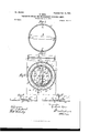
Figure1isaviewofthelampcomplete. Fig. 2 shows the device after the removal of the incandescent lamp, of the glass shade, and of the reflector. Fig. 3 is a vertical central section of the whole lamp. Fig. 4 is a plan of the ring t'. Fig. 5 is a cross-section of this ring 2'. Fig. 6 shows the normal position of the contact-maker, (lamp extinguished.) Fig. 7 shows the position of the contact-maker when the same is closed, (lamp burning.) Fig. 8 is a view corresponding to Fig. 2 of a modi fied form of the protective device.
Upon a wall at is' fixed the ring b. Within this ring and on the bottom of the plate is arranged the contact-piece c, Fig. 2, the latter being screwed home and carrying the wire 0, the end of which has the form of a hook. On the opposite side is placed the contact-piece d, which carries at the top another wire c ,whose free end is bent over to form a hook. The two hooks c and c serve to suspend the incandescent lamp and to convey the current thereto. The plate at carries a contact maker and breaker lever or key 6, fulcrumed on 0, Figs. 2 and 6, and provided at the top with a rounded-oft pin (2, Fig. 3. The sliding contactf, Figs. 1, 2, 3, 6, 7, and 8, is guided in a parts b, c, d, and 0 Fig. 2.
slot of the ring I) and is prevented from slip- Serial No. 688,363. (No model.)
ping down by the arm g of the two-armed spring 9 g bearing upon the pin f, its inward motion beiuglimited by the pin f striking the lever or key 6. The other arm g of this spring g g bears upon the lever or key 6 and tends constantly to bring the same into contact with the contact-piece 0 which can only be prevented by the springing therebetween of the sliding contact f, which pulls the spring 9 inwardly. The double spring g g is fixed by a screw to the piece 19 which is likewise screwed on the wall or plate a, as are the The reflector 'n, Fig. 1, is screwed onto the parts 6' and b Upon the outer periphery of the ring b are screwed the four springs h, Fig. 2, which are carried by the small screws h. The latter springs have for their object to hold the ring 2', to which the annular box 7", Figs. 1 and 3,
is fixed by means of screws m passing likewise through the pieces m on the one hand and through the holes m, formed in the bar is, Fig. 4, fixed rigidly to the said ring, on the other hand, while the screws m pass like- .wise through the angles of the springs h, Fig.
1, bent at their extremities in the form of a hook, in such a position that the said ring 1, with its annular box '1', is held above the plate a and is held fixed at the same time by the angles of the springs h and the screws m passthe lamp is extinguished. Upon the ring I) is screwed another ring c, Fig. 3. The rod 70 of the ring 'i rests in the recesses b of the ring b. Upon the ring '5 is screwed the ring S, wherein is fitted the hemispherical glass above referred to. The fitting up is carried out in such a manner that the ring '5 is first placed upon the ring b and is screwed up with the annular box by means of the small screws m Then the ring 1; is screwed upon b, after which the reflector 'n is screwed in position, while the incandescent lamp (1 is suspended to the wires 0 c and is held besides at its pointed end by the spring 1), fixed to the reflector n. Over the whole apparatus the ring 8, with the hemispherical glass or cover placed therein, is finally screwed upon the ring i.
This lamp operates in the following manner: To allow the electric current proceeding from the source of electricity placed at the back of the plate a, Fig. 3, to enter the lamp, the sliding contact is drawn down. As shown in Fig. 7, the lower part of the contact-lever 0 comes to bear under the action of the springs g upon the contact-piece 0 so that the electric current introduced through the latter passes along the wire 0, enters thelamp, and follows the wire 0' as far as the contact-piece c, the circuit being thus closed and the lamp burning. If now the glass of the ring 1' or the ring itself were to receive a knock or a blow, this ring would be sunk, the rod 70 would depress the pin 6', the lower part of the contact making or breaking key or lever e would be raised, and the slide f, urged on by the pressure of the spring g, would spring forward, so that this lever or key would come to bear on the slide, as atf, Fig. 6, and would break contact with the contact-piece 0 The current would then be broken and the lamp extinguished.
Fig. 8 shows a modification whereby when the glass is broken ignition cannot be communicated to the surrounding atmosphere without thoroughly smashing the lampthat is to say, when the lamp is extinguished it cannot be lighted again either accidentally or intentionally. In this modification the con tact-piece c is broken in the middle, consisting thus of two parts 0 and 0 The contact is now made or broken by the upper part it of the slide 15. All other parts of the device are similar to those hereinbefore described. The slide f is so shortened that it no longer projects out of the lamp, and hence cannot be further actuated independently, and, in consequence of pressure being exerted on the slide f outwardly and the restablishment of the contact between the lever e and the contact-pieces c and c ignition becomes a matter of impossibility unless the whole apparatus is smashed, and the slidef thus becomes depressed.
I claim 1. In combination with a protective cover for an electric lamp, a supporting device for said cover adapted to be depressed by the fracture or depression of said cover, and a circuit making and breaking device operated by a part or attachment of said supporting device, whereby the depression of said supportingdevice will break the circuit, substantially as set forth.
2. In combination with a protective cover for an electric lamp, a depressible ring to which the said cover is attached, a rod 7c moving with the said ring and cover, a circuitmaking lever 6 provided with apin 6' arranged to be acted on by said rod when the latter is thus depressed, a contact-piece arranged for normal contact with the said lever, and electrical connections making circuit through the said lever and contact-piece, the depression of the said ring and rod serving to move the said lever away from the said contact-piece and thereby break the circuit, substantially as set forth.
3. In combination with the protective cover of an electric lamp and its movable support, an attachment depressible with the said support, a circuit-breaking lever arranged to be moved out of contact by the said attachment when thus depressed, a fixed contact-piece which is normally in contact with the said lever, a sliding piece which may be moved to open or close the circuit, electric conductors making circuit through the said lever, movable piece and fixed contact-piece, and a twoarmed replacin g-sprin g which acts on the said sliding piece and lever, substantially as set forth.
In testimony whereof I affix my signature in presence of two witnesses.
RICHARD KAES.
\Vitnesses:
JAMES J. OPPENHEIM, IGNAX UBLEIS.
Publications (1)
| Publication Number | Publication Date |
|---|---|
| US619829A true US619829A (en) | 1899-02-21 |
Family
ID=2688438
Family Applications (1)
| Application Number | Title | Priority Date | Filing Date |
|---|---|---|---|
| US619829D Expired - Lifetime US619829A (en) | Protective device for incandescent electric lamps |
Country Status (1)
| Country | Link |
|---|---|
| US (1) | US619829A (en) |
-
0
- US US619829D patent/US619829A/en not_active Expired - Lifetime
Similar Documents
| Publication | Publication Date | Title |
|---|---|---|
| US619829A (en) | Protective device for incandescent electric lamps | |
| US618706A (en) | Electric lamp | |
| US413708A (en) | Electric safety lamp for miners | |
| US565541A (en) | Socket for incandescent lamps | |
| US1102639A (en) | Pull-switch socket. | |
| US251126A (en) | Samuel d | |
| US511229A (en) | Albert zo | |
| US506347A (en) | Electric cigar-lighter | |
| US932273A (en) | Electrically lighting up gas-lamps. | |
| US686172A (en) | Electric headlight-lamp. | |
| US778444A (en) | Electric cigar-lighter. | |
| US759444A (en) | Globe or shade holder. | |
| US522727A (en) | Electric lamplighter | |
| US492913A (en) | Electric lamp-lighter | |
| US660842A (en) | Illuminated flower. | |
| US1376243A (en) | Safety-lamp | |
| US998849A (en) | Electric lantern. | |
| US581718A (en) | Electric cigar-lighter | |
| US562850A (en) | Frank o | |
| US773411A (en) | Electric igniter. | |
| US397109A (en) | Switch and cut-out for electric light and other electrical devices | |
| US692735A (en) | Combined electric switch and spark-blow-out mechanism. | |
| US509085A (en) | Christian j | |
| US252364A (en) | Island | |
| US1643940A (en) | Electric-lighting fixture |