US6189503B1 - Porting arrangement for direct injected engine - Google Patents
Porting arrangement for direct injected engine Download PDFInfo
- Publication number
- US6189503B1 US6189503B1 US09/309,962 US30996299A US6189503B1 US 6189503 B1 US6189503 B1 US 6189503B1 US 30996299 A US30996299 A US 30996299A US 6189503 B1 US6189503 B1 US 6189503B1
- Authority
- US
- United States
- Prior art keywords
- cylinder head
- intake
- pair
- cylinder
- openings
- Prior art date
- Legal status (The legal status is an assumption and is not a legal conclusion. Google has not performed a legal analysis and makes no representation as to the accuracy of the status listed.)
- Expired - Fee Related
Links
- 238000002485 combustion reaction Methods 0.000 claims abstract description 28
- 239000000446 fuel Substances 0.000 claims abstract description 20
- 238000005507 spraying Methods 0.000 claims description 5
- 238000010276 construction Methods 0.000 description 6
- 230000000712 assembly Effects 0.000 description 3
- 238000000429 assembly Methods 0.000 description 3
- 238000002347 injection Methods 0.000 description 2
- 239000007924 injection Substances 0.000 description 2
- 238000000034 method Methods 0.000 description 2
- 230000015572 biosynthetic process Effects 0.000 description 1
- 230000006835 compression Effects 0.000 description 1
- 238000007906 compression Methods 0.000 description 1
- 238000011217 control strategy Methods 0.000 description 1
- 239000007789 gas Substances 0.000 description 1
- 230000006698 induction Effects 0.000 description 1
- 230000002452 interceptive effect Effects 0.000 description 1
- 238000012986 modification Methods 0.000 description 1
- 230000004048 modification Effects 0.000 description 1
- 230000029058 respiratory gaseous exchange Effects 0.000 description 1
- 239000007921 spray Substances 0.000 description 1
- 238000013517 stratification Methods 0.000 description 1
Images


Classifications
-
- F—MECHANICAL ENGINEERING; LIGHTING; HEATING; WEAPONS; BLASTING
- F02—COMBUSTION ENGINES; HOT-GAS OR COMBUSTION-PRODUCT ENGINE PLANTS
- F02M—SUPPLYING COMBUSTION ENGINES IN GENERAL WITH COMBUSTIBLE MIXTURES OR CONSTITUENTS THEREOF
- F02M35/00—Combustion-air cleaners, air intakes, intake silencers, or induction systems specially adapted for, or arranged on, internal-combustion engines
- F02M35/10—Air intakes; Induction systems
- F02M35/10209—Fluid connections to the air intake system; their arrangement of pipes, valves or the like
- F02M35/10216—Fuel injectors; Fuel pipes or rails; Fuel pumps or pressure regulators
-
- F—MECHANICAL ENGINEERING; LIGHTING; HEATING; WEAPONS; BLASTING
- F01—MACHINES OR ENGINES IN GENERAL; ENGINE PLANTS IN GENERAL; STEAM ENGINES
- F01L—CYCLICALLY OPERATING VALVES FOR MACHINES OR ENGINES
- F01L1/00—Valve-gear or valve arrangements, e.g. lift-valve gear
- F01L1/02—Valve drive
- F01L1/04—Valve drive by means of cams, camshafts, cam discs, eccentrics or the like
- F01L1/047—Camshafts
- F01L1/053—Camshafts overhead type
- F01L1/0532—Camshafts overhead type the cams being directly in contact with the driven valve
-
- F—MECHANICAL ENGINEERING; LIGHTING; HEATING; WEAPONS; BLASTING
- F01—MACHINES OR ENGINES IN GENERAL; ENGINE PLANTS IN GENERAL; STEAM ENGINES
- F01L—CYCLICALLY OPERATING VALVES FOR MACHINES OR ENGINES
- F01L1/00—Valve-gear or valve arrangements, e.g. lift-valve gear
- F01L1/26—Valve-gear or valve arrangements, e.g. lift-valve gear characterised by the provision of two or more valves operated simultaneously by same transmitting-gear; peculiar to machines or engines with more than two lift-valves per cylinder
-
- F—MECHANICAL ENGINEERING; LIGHTING; HEATING; WEAPONS; BLASTING
- F01—MACHINES OR ENGINES IN GENERAL; ENGINE PLANTS IN GENERAL; STEAM ENGINES
- F01L—CYCLICALLY OPERATING VALVES FOR MACHINES OR ENGINES
- F01L1/00—Valve-gear or valve arrangements, e.g. lift-valve gear
- F01L1/46—Component parts, details, or accessories, not provided for in preceding subgroups
-
- F—MECHANICAL ENGINEERING; LIGHTING; HEATING; WEAPONS; BLASTING
- F02—COMBUSTION ENGINES; HOT-GAS OR COMBUSTION-PRODUCT ENGINE PLANTS
- F02B—INTERNAL-COMBUSTION PISTON ENGINES; COMBUSTION ENGINES IN GENERAL
- F02B31/00—Modifying induction systems for imparting a rotation to the charge in the cylinder
- F02B31/08—Modifying induction systems for imparting a rotation to the charge in the cylinder having multiple air inlets
- F02B31/085—Modifying induction systems for imparting a rotation to the charge in the cylinder having multiple air inlets having two inlet valves
-
- F—MECHANICAL ENGINEERING; LIGHTING; HEATING; WEAPONS; BLASTING
- F02—COMBUSTION ENGINES; HOT-GAS OR COMBUSTION-PRODUCT ENGINE PLANTS
- F02B—INTERNAL-COMBUSTION PISTON ENGINES; COMBUSTION ENGINES IN GENERAL
- F02B63/00—Adaptations of engines for driving pumps, hand-held tools or electric generators; Portable combinations of engines with engine-driven devices
- F02B63/06—Adaptations of engines for driving pumps, hand-held tools or electric generators; Portable combinations of engines with engine-driven devices for pumps
-
- F—MECHANICAL ENGINEERING; LIGHTING; HEATING; WEAPONS; BLASTING
- F02—COMBUSTION ENGINES; HOT-GAS OR COMBUSTION-PRODUCT ENGINE PLANTS
- F02M—SUPPLYING COMBUSTION ENGINES IN GENERAL WITH COMBUSTIBLE MIXTURES OR CONSTITUENTS THEREOF
- F02M35/00—Combustion-air cleaners, air intakes, intake silencers, or induction systems specially adapted for, or arranged on, internal-combustion engines
- F02M35/10—Air intakes; Induction systems
- F02M35/10006—Air intakes; Induction systems characterised by the position of elements of the air intake system in direction of the air intake flow, i.e. between ambient air inlet and supply to the combustion chamber
- F02M35/10078—Connections of intake systems to the engine
- F02M35/10085—Connections of intake systems to the engine having a connecting piece, e.g. a flange, between the engine and the air intake being foreseen with a throttle valve, fuel injector, mixture ducts or the like
-
- F—MECHANICAL ENGINEERING; LIGHTING; HEATING; WEAPONS; BLASTING
- F02—COMBUSTION ENGINES; HOT-GAS OR COMBUSTION-PRODUCT ENGINE PLANTS
- F02M—SUPPLYING COMBUSTION ENGINES IN GENERAL WITH COMBUSTIBLE MIXTURES OR CONSTITUENTS THEREOF
- F02M35/00—Combustion-air cleaners, air intakes, intake silencers, or induction systems specially adapted for, or arranged on, internal-combustion engines
- F02M35/10—Air intakes; Induction systems
- F02M35/104—Intake manifolds
- F02M35/108—Intake manifolds with primary and secondary intake passages
- F02M35/1085—Intake manifolds with primary and secondary intake passages the combustion chamber having multiple intake valves
-
- F—MECHANICAL ENGINEERING; LIGHTING; HEATING; WEAPONS; BLASTING
- F02—COMBUSTION ENGINES; HOT-GAS OR COMBUSTION-PRODUCT ENGINE PLANTS
- F02M—SUPPLYING COMBUSTION ENGINES IN GENERAL WITH COMBUSTIBLE MIXTURES OR CONSTITUENTS THEREOF
- F02M37/00—Apparatus or systems for feeding liquid fuel from storage containers to carburettors or fuel-injection apparatus; Arrangements for purifying liquid fuel specially adapted for, or arranged on, internal-combustion engines
- F02M37/04—Feeding by means of driven pumps
- F02M37/06—Feeding by means of driven pumps mechanically driven
-
- F—MECHANICAL ENGINEERING; LIGHTING; HEATING; WEAPONS; BLASTING
- F02—COMBUSTION ENGINES; HOT-GAS OR COMBUSTION-PRODUCT ENGINE PLANTS
- F02B—INTERNAL-COMBUSTION PISTON ENGINES; COMBUSTION ENGINES IN GENERAL
- F02B75/00—Other engines
- F02B75/12—Other methods of operation
- F02B2075/125—Direct injection in the combustion chamber for spark ignition engines, i.e. not in pre-combustion chamber
-
- F—MECHANICAL ENGINEERING; LIGHTING; HEATING; WEAPONS; BLASTING
- F02—COMBUSTION ENGINES; HOT-GAS OR COMBUSTION-PRODUCT ENGINE PLANTS
- F02B—INTERNAL-COMBUSTION PISTON ENGINES; COMBUSTION ENGINES IN GENERAL
- F02B2275/00—Other engines, components or details, not provided for in other groups of this subclass
- F02B2275/18—DOHC [Double overhead camshaft]
-
- F—MECHANICAL ENGINEERING; LIGHTING; HEATING; WEAPONS; BLASTING
- F02—COMBUSTION ENGINES; HOT-GAS OR COMBUSTION-PRODUCT ENGINE PLANTS
- F02B—INTERNAL-COMBUSTION PISTON ENGINES; COMBUSTION ENGINES IN GENERAL
- F02B2275/00—Other engines, components or details, not provided for in other groups of this subclass
- F02B2275/48—Tumble motion in gas movement in cylinder
-
- Y—GENERAL TAGGING OF NEW TECHNOLOGICAL DEVELOPMENTS; GENERAL TAGGING OF CROSS-SECTIONAL TECHNOLOGIES SPANNING OVER SEVERAL SECTIONS OF THE IPC; TECHNICAL SUBJECTS COVERED BY FORMER USPC CROSS-REFERENCE ART COLLECTIONS [XRACs] AND DIGESTS
- Y02—TECHNOLOGIES OR APPLICATIONS FOR MITIGATION OR ADAPTATION AGAINST CLIMATE CHANGE
- Y02T—CLIMATE CHANGE MITIGATION TECHNOLOGIES RELATED TO TRANSPORTATION
- Y02T10/00—Road transport of goods or passengers
- Y02T10/10—Internal combustion engine [ICE] based vehicles
- Y02T10/12—Improving ICE efficiencies
Definitions
- This invention relates to a porting arrangement for a direct injected internal combustion engine and more particular to an improved cylinder head arrangement for such an engine.
- each intake passage can function independently of the others under some running conditions and/or so as to induce turbulence under one running condition without increasing flow resistance at high speed high load conditions.
- direct cylinder injection also can be employed in order to improve engine performance.
- This invention is adapted to be embodied in a cylinder head for an internal combustion engine having a lower surface adapted to be affixed in engagement with a corresponding surface of a cylinder block.
- the cylinder head has a recessed area in its lower surface cooperating with a cylinder bore in the cylinder block to form, in part, a combustion chamber.
- a pair of valve seats are formed in the cylinder head recess on one side thereof.
- a pair of intake passages each extending from a respective one of the intake ports to a pair of spaced apart inlet openings formed in an outer surface of the cylinder head.
- a fuel injector is mounted in the cylinder head below the intake passages and disposed therebetween. The fuel injector is received in an opening formed in the cylinder head that is disposed between and below the intake passage openings for receiving a fuel injector for spraying directly into the cylinder head recess.
- FIG. 1 is a cross-sectional view taken through a portion of a cylinder head of an internal combustion engine constructed in accordance with an embodiment of the invention and with some of the components removed and others shown in phantom.
- FIG. 2 is a cross-sectional view taken along a plane parallel to that of FIG. 1 but passing through the center of the cylinder bore of the cylinder block.
- FIG. 3 is a side elevational view of the cylinder head with its components removed and looking in the direction of the arrow 3 in FIG. 1 .
- FIG. 4 is a view looking in the same direction as FIG. 3 but shows the control valve body arrangement associated with the induction system and which forms a continuation of the cylinder head intake passages.
- FIG. 5 is a partially schematic top plan view showing the porting arrangement associated with the engine.
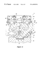
- FIG. 6 is a perspective view showing the porting configuration and looking from above and outwardly from the center of the cylinder bore.
- FIG. 7 is a perspective view looking generally in the opposite direction from FIG. 6 and showing the same components.
- FIGS. 1 and 2 an internal combustion engine constructed in accordance with an embodiment of the invention is shown partially and is identified generally by the reference numeral 11 .
- the invention deals, as should be apparent from the foregoing description, primarily with the construction of the cylinder head assembly, indicated by the reference numeral 12 and the porting arrangement therefore. Therefore, where components of the engine are not necessary to illustrate this construction, nor permit those skilled in the art to practice the invention, they have not been illustrated nor will be they described except generally. Therefore, where any components of the engine 11 do not appear in the drawings or are not described herein, those skilled in the art may resort to any suitable constructions with which to practice the invention.
- the cylinder head assembly 12 is attached to a cylinder block 13 in any suitable manner.
- the cylinder block 13 is formed with one or more cylinder bores 14 which are closed by a main cylinder head member 15 of the cylinder head assembly 12 .
- the construction shown in the figures represents a multiple cylinder, incline type engine. It should be readily apparent, however, to those skilled in the art how to practice the invention with engines having other cylinder numbers and other configurations.
- the cylinder head member 15 has recesses 16 in its lower surface which cooperate with the cylinder bores 14 and pistons 17 that reciprocate therein to form the variable volume chambers of the engine which will be at times referred to as the “combustion chambers”.
- the cylinder head recess 16 forms substantially the entire volume of the combustion chamber and at times this reference numeral will be used to designate the combustion chamber.
- the engine 11 is of the multiple valve per cylinder type and includes at least two intake valves 18 which have stem portions 19 that are supported for reciprocation in valve guides 21 in the cylinder head member 15 .
- These intake valves 18 control the opening and closing of intake ports 22 that are formed at the termination of a pair of side-by-side intake passages 23 which are formed the cylinder head member 15 and which are totally separated from each other by a wall, shown in FIG. 5 and indicated by the reference numeral 24 . This wall also appears in FIG. 3 .
- the intake passages 23 extend outwardly and terminate in openings formed in an external surface 25 of the cylinder head member 16 .
- a control valve body, indicated generally by the reference numeral 26 is affixed to this surface 25 and has branch passages 27 which are separated also from each other for a portion of their length by an integral wall 28 which forms an extension of the cylinder head wall 27 .
- the control valve body 26 mates with a suitable intake manifold and air supply system which is not shown.
- This system may include one or more speed controlling throttle valves.
- the control valve body 26 includes a butterfly type control valve 29 which is mounted on a control valve shaft 31 in the body 26 in only one of the two intake passages 27 thereof associated with each cylinder.
- a butterfly type control valve 29 which is mounted on a control valve shaft 31 in the body 26 in only one of the two intake passages 27 thereof associated with each cylinder.
- a swirl indicated by the arrow S in FIG. 5 can be generated. This can be used to promote turbulence under low and mid range operation so as to improve flame propagation and, at times, to control stratification within the combustion chamber 16 .
- tumble can be created by utilizing a properly configured and located valve. In addition both swirl and tumble can be created either simultaneously or sequentially.
- the control valve 29 is operated by a servo motor 32 that is affixed to the control valve shaft 31 and which is controlled by a suitable EMU in connection with a desired control strategy.
- the cylinder head intake passages 27 have a generally rectangular configuration that merges toward their discharge ends at the ports 22 in a circular or cylindrical configuration.
- this type of configuration it is possible to obtain a larger flow area without making the cylinder head unduly large and also to provide a recessed area 33 (see FIG. 3) that extends beneath and between the two intake passages 23 for each cylinder.
- This recessed area 33 permits the formation of an opening 34 which receives a fuel injector 35 as best seen in FIG. 2 .
- the fuel injector 35 can be positioned so as to have the optimum spray pattern within the combustion chamber.
- the control valve body 26 has like recesses 40 (FIG. 4) for a similar purpose.
- the intake valves 18 are urged to their closed positions by means of coil spring assemblies 36 which are loaded between a surface of the cylinder head member and a keeper retainer assembly which is not shown but which is affixed to the upper end of the stem portion 19 of the intake valves 18 .
- Thimble tappets 37 are received in bosses 38 formed in the cylinder head member 15 and bear against these keeper retainer assemblies.
- the thimble tappets 37 are actuated by the lobes 39 of an intake cam shaft 41 that is journaled for rotation in a suitable manner within the cylinder head member 15 .
- This intake cam shaft is driven at one half crankshaft speed by a suitable timing drive, as is well known in the art.
- the intake cam shaft 41 is journaled by bearing surfaces formed in the cylinder head member 15 and by bearing caps 42 that are affixed thereto by threaded fasteners 43 .
- a spark plug well 44 Centrally of the cylinder head member 15 there is provided a spark plug well 44 in which a spark plug 45 is received.
- the spark plug 45 is positioned so that its spark gap 46 lies substantially on the axis of the cylinder bore 14 and hence, generally at the center of the combustion chamber 16 . This ensures equal flame propagation and complete combustion in the combustion chamber.
- the burnt charge is discharged from the combustion chamber 16 through exhaust ports 47 which are formed at the inlet ends of a Siamesed type exhaust passage, indicated generally by the reference numeral 48 .
- This passage 48 has individual portions 49 that merge into a common discharge opening 51 formed in an outer surface 52 of the cylinder head member 15 .
- An exhaust manifold, shown schematically at 53 is affixed to the surface 52 and collects the exhaust gases for discharge to the atmosphere in a known manner.
- the exhaust ports 47 are valved by the heads of exhaust valves 54 .
- the exhaust valves 54 have stem portions 55 that are supported within valve guides 56 in the cylinder head 15 .
- coil compression spring 57 act against the cylinder head member 15 and keep a retainer assembly affixed to the upper ends of the valve stems 55 for holding them in closed positions.
- Thimble tappets 58 are slidably supported in bores formed in bosses 59 of the cylinder head member 15 and engage these keeper retainer assemblies.
- the lobe 61 of an exhaust cam shaft 62 cooperate with the thimble tappets 58 for opening exhaust valves 54 in a well known manner.
- the exhaust cam shaft 62 is, like the intake cam shaft 41 , driven at one half crankshaft speed by any suitable drive.
- the exhaust cam shaft 62 is also journaled in the cylinder head member 15 by integral bearing surfaces.
- Bearing caps 63 are affixed thereto by the threaded fasteners 43 .
- cam shafts 41 and 62 are journaled in a cam chamber 64 that is formed by the cylinder head member 15 and a cam cover 65 which is affixed thereto also by the threaded fasteners 43 .
- the cam cover 65 has a flange portion 66 which is grooved at 67 so as to receive a seal 68 that is sealingly engaged with the exterior surface of the cylinder head member 15 around this cam chamber 64 .
- the described cylinder head and porting arrangement provides a very large effective flow area without interfering with the desired placement of the fuel injector.
- the arrangement utilizing the control valve assembly 26 permits desired types of turbulence to be generated in one or if desired both of the intake passage but different from each other. This is done why still permitting the use of a common intake opening that can be controlled by a single throttle valve.
Landscapes
- Engineering & Computer Science (AREA)
- Mechanical Engineering (AREA)
- General Engineering & Computer Science (AREA)
- Chemical & Material Sciences (AREA)
- Combustion & Propulsion (AREA)
- Fuel-Injection Apparatus (AREA)
- Cylinder Crankcases Of Internal Combustion Engines (AREA)
Abstract
Description
Claims (10)
Applications Claiming Priority (2)
| Application Number | Priority Date | Filing Date | Title |
|---|---|---|---|
| JP10-130927 | 1998-05-14 | ||
| JP10130927A JP2000257533A (en) | 1998-05-14 | 1998-05-14 | Internal combustion engine |
Publications (1)
| Publication Number | Publication Date |
|---|---|
| US6189503B1 true US6189503B1 (en) | 2001-02-20 |
Family
ID=15045988
Family Applications (1)
| Application Number | Title | Priority Date | Filing Date |
|---|---|---|---|
| US09/309,962 Expired - Fee Related US6189503B1 (en) | 1998-05-14 | 1999-05-11 | Porting arrangement for direct injected engine |
Country Status (2)
| Country | Link |
|---|---|
| US (1) | US6189503B1 (en) |
| JP (1) | JP2000257533A (en) |
Cited By (8)
| Publication number | Priority date | Publication date | Assignee | Title |
|---|---|---|---|---|
| US6367444B1 (en) * | 1998-08-27 | 2002-04-09 | Yamaha Hatsudoki Kabushiki Kaisha | Cylinder head for direct injected engine |
| US20030015170A1 (en) * | 2001-06-27 | 2003-01-23 | Filterwerk Mann & Hummel Gmbh | Intermediate flange system for an internal combustion engine with direct fuel injection |
| US6691673B2 (en) | 2001-08-22 | 2004-02-17 | Yamaha Marine Kabushiki Kaisha | Fuel supply device for outboard motor |
| US6752114B2 (en) | 2001-10-25 | 2004-06-22 | Yamaha Marine Kabushiki Kaisha | Four-cycle engine for outboard motor |
| US6830029B2 (en) | 2001-08-22 | 2004-12-14 | Yamaha Marine Kabushiki Kaisah | Fuel supply device for outboard motor |
| CN101737216A (en) * | 2008-11-25 | 2010-06-16 | 现代自动车株式会社 | Direct gasolene injection engine equipped with oil fuel pump |
| US20120298074A1 (en) * | 2011-05-24 | 2012-11-29 | Yamaha Hatsudoki Kabushiki Kaisha | Four-stroke engine |
| US20220412284A1 (en) * | 2019-12-24 | 2022-12-29 | Fleetguard Filters Private Limited | Cylinder cover for internal combustion engine |
Citations (5)
| Publication number | Priority date | Publication date | Assignee | Title |
|---|---|---|---|---|
| US5775288A (en) * | 1995-08-17 | 1998-07-07 | Yamaha Hatsudoki Kabushiki Kaisha | Combustion chamber |
| US5915353A (en) * | 1997-05-21 | 1999-06-29 | Nissan Motor Co., Ltd | Cylinder direct injection spark-ignition engine |
| US5960768A (en) * | 1997-05-29 | 1999-10-05 | Institut Francais Du Petrole | Arrangement of a direct-injection and spark-ignition 4-stroke internal-combustion engine |
| US6006719A (en) * | 1997-05-21 | 1999-12-28 | Nissan Motor Co., Ltd. | Cylinder direct injection spark-ignition engine |
| US6009849A (en) * | 1996-08-12 | 2000-01-04 | Mazda Motor Corporation | Direct fuel injection engine |
-
1998
- 1998-05-14 JP JP10130927A patent/JP2000257533A/en active Pending
-
1999
- 1999-05-11 US US09/309,962 patent/US6189503B1/en not_active Expired - Fee Related
Patent Citations (5)
| Publication number | Priority date | Publication date | Assignee | Title |
|---|---|---|---|---|
| US5775288A (en) * | 1995-08-17 | 1998-07-07 | Yamaha Hatsudoki Kabushiki Kaisha | Combustion chamber |
| US6009849A (en) * | 1996-08-12 | 2000-01-04 | Mazda Motor Corporation | Direct fuel injection engine |
| US5915353A (en) * | 1997-05-21 | 1999-06-29 | Nissan Motor Co., Ltd | Cylinder direct injection spark-ignition engine |
| US6006719A (en) * | 1997-05-21 | 1999-12-28 | Nissan Motor Co., Ltd. | Cylinder direct injection spark-ignition engine |
| US5960768A (en) * | 1997-05-29 | 1999-10-05 | Institut Francais Du Petrole | Arrangement of a direct-injection and spark-ignition 4-stroke internal-combustion engine |
Cited By (12)
| Publication number | Priority date | Publication date | Assignee | Title |
|---|---|---|---|---|
| US6367444B1 (en) * | 1998-08-27 | 2002-04-09 | Yamaha Hatsudoki Kabushiki Kaisha | Cylinder head for direct injected engine |
| US20030015170A1 (en) * | 2001-06-27 | 2003-01-23 | Filterwerk Mann & Hummel Gmbh | Intermediate flange system for an internal combustion engine with direct fuel injection |
| US6732712B2 (en) * | 2001-06-27 | 2004-05-11 | Filterwerk Mann & Hummel Gmbh | Intermediate flange system for an internal combustion engine with direct fuel injection |
| US6691673B2 (en) | 2001-08-22 | 2004-02-17 | Yamaha Marine Kabushiki Kaisha | Fuel supply device for outboard motor |
| US6830029B2 (en) | 2001-08-22 | 2004-12-14 | Yamaha Marine Kabushiki Kaisah | Fuel supply device for outboard motor |
| US6752114B2 (en) | 2001-10-25 | 2004-06-22 | Yamaha Marine Kabushiki Kaisha | Four-cycle engine for outboard motor |
| CN101737216A (en) * | 2008-11-25 | 2010-06-16 | 现代自动车株式会社 | Direct gasolene injection engine equipped with oil fuel pump |
| CN101737216B (en) * | 2008-11-25 | 2013-12-04 | 现代自动车株式会社 | Direct gasolene injection engine equipped with oil fuel pump |
| US20120298074A1 (en) * | 2011-05-24 | 2012-11-29 | Yamaha Hatsudoki Kabushiki Kaisha | Four-stroke engine |
| US9458807B2 (en) * | 2011-05-24 | 2016-10-04 | Yamaha Hatsudoki Kabushiki Kaisha | Four-stroke engine |
| US20220412284A1 (en) * | 2019-12-24 | 2022-12-29 | Fleetguard Filters Private Limited | Cylinder cover for internal combustion engine |
| US11767805B2 (en) * | 2019-12-24 | 2023-09-26 | Fleetguard Filters Private Limited | Cylinder cover for internal combustion engine |
Also Published As
| Publication number | Publication date |
|---|---|
| JP2000257533A (en) | 2000-09-19 |
Similar Documents
| Publication | Publication Date | Title |
|---|---|---|
| US5709190A (en) | Combustion chamber and induction system for engine | |
| US5477823A (en) | Control valve for engine intake control system | |
| US5735240A (en) | Direct injected engine | |
| EP1057982A2 (en) | Four-stroke cycle engine | |
| US5799638A (en) | Direction injection system for multi-valve engine | |
| US5671712A (en) | Induction system for engine | |
| US5630386A (en) | Intake structure for V-type engine | |
| US5535714A (en) | Cylinder head arrangement for multi-valve engine | |
| US5826560A (en) | Engine combustion chamber and method of operation | |
| US5487365A (en) | Induction system for engine | |
| US5529038A (en) | Direct injected engine | |
| EP0595316B1 (en) | Cylinder head and valve arrangement of a multi-valve internal combustion engine | |
| US6189503B1 (en) | Porting arrangement for direct injected engine | |
| US4651696A (en) | Four-stroke internal combustion engine | |
| US5787851A (en) | Intake control system | |
| US5307773A (en) | Squish structure for spark ignition engine | |
| US4622940A (en) | Porting arrangement for internal combustion engine | |
| US5101777A (en) | Automobile engine structure | |
| US7273032B2 (en) | Engine induction system | |
| US6708667B2 (en) | Combustion chamber structure of in-cylinder fuel injection type engine | |
| JPS6149120A (en) | 4 stroke internal-combustion engine | |
| US20010029917A1 (en) | Intake control device for multi-cylinder V-type engine | |
| US4572117A (en) | Valve arrangement for an internal combustion engine | |
| EP0610679B1 (en) | Induction system for engine | |
| US4911113A (en) | Valve actuating device for multiple valve type engine |
Legal Events
| Date | Code | Title | Description |
|---|---|---|---|
| AS | Assignment |
Owner name: YAMAHA HATSUDOKI KABUSHIKI KAISHA, JAPAN Free format text: ASSIGNMENT OF ASSIGNORS INTEREST;ASSIGNOR:TAKANO, TOMOTAKA;REEL/FRAME:009956/0967 Effective date: 19990427 |
|
| FEPP | Fee payment procedure |
Free format text: PAYOR NUMBER ASSIGNED (ORIGINAL EVENT CODE: ASPN); ENTITY STATUS OF PATENT OWNER: LARGE ENTITY Free format text: PAYER NUMBER DE-ASSIGNED (ORIGINAL EVENT CODE: RMPN); ENTITY STATUS OF PATENT OWNER: LARGE ENTITY |
|
| FPAY | Fee payment |
Year of fee payment: 4 |
|
| FPAY | Fee payment |
Year of fee payment: 8 |
|
| FEPP | Fee payment procedure |
Free format text: PAYOR NUMBER ASSIGNED (ORIGINAL EVENT CODE: ASPN); ENTITY STATUS OF PATENT OWNER: LARGE ENTITY Free format text: PAYER NUMBER DE-ASSIGNED (ORIGINAL EVENT CODE: RMPN); ENTITY STATUS OF PATENT OWNER: LARGE ENTITY |
|
| REMI | Maintenance fee reminder mailed | ||
| LAPS | Lapse for failure to pay maintenance fees | ||
| STCH | Information on status: patent discontinuation |
Free format text: PATENT EXPIRED DUE TO NONPAYMENT OF MAINTENANCE FEES UNDER 37 CFR 1.362 |
|
| FP | Lapsed due to failure to pay maintenance fee |
Effective date: 20130220 |