US6180283B1 - Method for reducing voltage delay in an alkali metal electrochemical cell activated with a nonaqueous electrolyte having a sulfate additive - Google Patents
Method for reducing voltage delay in an alkali metal electrochemical cell activated with a nonaqueous electrolyte having a sulfate additive Download PDFInfo
- Publication number
- US6180283B1 US6180283B1 US09/460,035 US46003599A US6180283B1 US 6180283 B1 US6180283 B1 US 6180283B1 US 46003599 A US46003599 A US 46003599A US 6180283 B1 US6180283 B1 US 6180283B1
- Authority
- US
- United States
- Prior art keywords
- sulfate
- mono
- bis
- group
- pulse
- Prior art date
- Legal status (The legal status is an assumption and is not a legal conclusion. Google has not performed a legal analysis and makes no representation as to the accuracy of the status listed.)
- Expired - Lifetime
Links
Images


Classifications
-
- H—ELECTRICITY
- H01—ELECTRIC ELEMENTS
- H01M—PROCESSES OR MEANS, e.g. BATTERIES, FOR THE DIRECT CONVERSION OF CHEMICAL ENERGY INTO ELECTRICAL ENERGY
- H01M6/00—Primary cells; Manufacture thereof
- H01M6/14—Cells with non-aqueous electrolyte
- H01M6/16—Cells with non-aqueous electrolyte with organic electrolyte
- H01M6/162—Cells with non-aqueous electrolyte with organic electrolyte characterised by the electrolyte
- H01M6/168—Cells with non-aqueous electrolyte with organic electrolyte characterised by the electrolyte by additives
-
- H—ELECTRICITY
- H01—ELECTRIC ELEMENTS
- H01M—PROCESSES OR MEANS, e.g. BATTERIES, FOR THE DIRECT CONVERSION OF CHEMICAL ENERGY INTO ELECTRICAL ENERGY
- H01M4/00—Electrodes
- H01M4/02—Electrodes composed of, or comprising, active material
- H01M4/62—Selection of inactive substances as ingredients for active masses, e.g. binders, fillers
- H01M4/624—Electric conductive fillers
- H01M4/626—Metals
-
- H—ELECTRICITY
- H01—ELECTRIC ELEMENTS
- H01M—PROCESSES OR MEANS, e.g. BATTERIES, FOR THE DIRECT CONVERSION OF CHEMICAL ENERGY INTO ELECTRICAL ENERGY
- H01M6/00—Primary cells; Manufacture thereof
- H01M6/50—Methods or arrangements for servicing or maintenance, e.g. for maintaining operating temperature
- H01M6/5088—Initial activation; predischarge; Stabilisation of initial voltage
-
- H—ELECTRICITY
- H01—ELECTRIC ELEMENTS
- H01M—PROCESSES OR MEANS, e.g. BATTERIES, FOR THE DIRECT CONVERSION OF CHEMICAL ENERGY INTO ELECTRICAL ENERGY
- H01M2300/00—Electrolytes
- H01M2300/0017—Non-aqueous electrolytes
- H01M2300/0025—Organic electrolyte
- H01M2300/0028—Organic electrolyte characterised by the solvent
- H01M2300/0037—Mixture of solvents
-
- H—ELECTRICITY
- H01—ELECTRIC ELEMENTS
- H01M—PROCESSES OR MEANS, e.g. BATTERIES, FOR THE DIRECT CONVERSION OF CHEMICAL ENERGY INTO ELECTRICAL ENERGY
- H01M6/00—Primary cells; Manufacture thereof
- H01M6/14—Cells with non-aqueous electrolyte
- H01M6/16—Cells with non-aqueous electrolyte with organic electrolyte
- H01M6/162—Cells with non-aqueous electrolyte with organic electrolyte characterised by the electrolyte
- H01M6/166—Cells with non-aqueous electrolyte with organic electrolyte characterised by the electrolyte by the solute
Definitions
- the present invention generally relates to an alkali metal electrochemical cell, and more particularly, to an alkali metal cell suitable for current pulse discharge applications with reduced or no appreciable voltage delay.
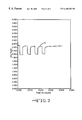
- FIG. 1 is a graph showing an illustrative discharge curve 10 as a typical or “ideal” response of a cell during the application of a series of pulses as a pulse train that does not exhibit voltage delay.
- the voltage response of a cell which exhibits voltage delay during the application of a short duration pulse or during a pulse train can take one or both of two forms.
- One form is that the leading edge potential of the first pulse is lower than the end edge potential of the first pulse.
- the second form of voltage delay is that the minimum potential of the first pulse is lower than the minimum potential of the last pulse when a series of pulses have been applied.
- FIG. 2 is a graph showing an illustrative discharge curve 12 as the voltage response of a cell that exhibits both forms of voltage delay.
- the initial drop in cell potential during the application of a short duration pulse reflects the resistance of the cell, i.e., the resistance due to the cathode, the cathode-electrolyte interphase, the anode, and the anode-electrolyte interphase.
- the resistance due to passivated films on the anode and/or cathode is negligible.
- the formation of a surface film is unavoidable for alkali metal, and in particular, lithium metal anodes, and for lithium intercalated carbon anodes, due to their relatively low potential and high reactivity towards organic electrolytes.
- the ideal anode surface film should be electrically insulating and ionically conducting.
- the second requirement is difficult to achieve.
- the resistance of these films is not negligible, and as a result, impedance builds up inside the cell due to this surface layer formation which often results in reduced discharge voltage and reduced cell capacity.
- the drop in potential between the background voltage and the lowest voltage under pulse discharge conditions, excluding voltage delay is an indication of the conductivity of the cell, i.e., the conductivity of the cathode, anode, electrolyte, and surface films, while the gradual decrease in cell potential during the application of the pulse train is due to the polarization of the electrodes and electrolyte.
- the present invention is directed to the provision of sulfate additives in the electrolyte of an alkali metal electrochemical cell to beneficially modify the anode surface film.
- the sulfate additives preferably include at least one unsaturated hydrocarbon containing a C(sp 2 or sp 3 )—C(sp 3 ) bond unit having the C(sp 3 ) carbon directly connected to the —OSO 3 — functional group, or are a silyl sulfate or a tin sulfate, and are provided as a co-solvent with commonly used organic aprotic solvents.
- the organic sulfate additives are in a condensed phase which makes them easy to handle in electrolyte preparation.
- the sulfate additives When used as a co-solvent in an activating electrolyte, the sulfate additives interact with the alkali metal anode to form an conically conductive surface protective layer thereon.
- the conductive surface layer improves the discharge performance of the alkali metal electrochemical cell and minimizes or even eliminates voltage delay in the high current pulse discharge of such cells.
- the object of the present invention is to improve the pulse discharge performance of an alkali metal electrochemical cell, and more particularly a primary lithium electrochemical cell, by the provision of at least one of a family of sulfate additives as a co-solvent in the cell's activating nonaqueous electrolyte solution. Due to the high reduction potentials of the sulfate group vs. lithium, the sulfate additives can compete effectively with the other electrolyte co-solvents or the solute to react with the lithium anode. Lithium sulfate or the lithium salt of sulfate reduction products are believed to be the major reaction products. These lithium salts are believed to deposit on the anode surface to form an ionically conductive protective film thereon.
- the chemical composition and perhaps the morphology of the anode surface protective layer is changed, and this proves beneficial to the discharge characteristics of the cell.
- the thusly fabricated cell exhibits reduced or no appreciable voltage delay under current pulse discharge usage, which is an unexpected result.
- FIG. 1 is a graph showing an illustrative pulse discharge curve 10 of an exemplary electrochemical cell that does not exhibit voltage delay.
- FIG. 2 is a graph showing an illustrative pulse discharge curve 12 of an exemplary electrochemical cell that exhibits voltage delay.
- FIG. 3 is a graph showing the pulse discharge voltage curves of a lithium/silver vanadium oxide cell activated with an electrolyte devoid of an alkyl sulfate additive during the application of four 10 second pulses (23.2 mA/cm 2 ) with a 15 rest between each pulse.
- FIG. 4 is a graph showing the pulse discharge voltage curves of a lithium/silver vanadium oxide cell activated with an electrolyte having bis(trimethylsilyl) sulfate (BTMSS) dissolved therein during the application of a pulse train similar to that used to construct the graph of FIG. 3 .
- BTMSS bis(trimethylsilyl) sulfate
- pulse means a burst of electrical current of a greater amplitude than that of a pre-pulse current immediately prior to the pulse.
- a pulse train consists of at least two pulses of electrical current delivered in relatively short succession with or without open circuit rest between the pulses. Voltage delay is calculated as the pulse end potential minus the pulse minimum potential.
- the electrochemical cell of the present invention includes an anode selected from Group IA, IIA or IIIB of the Periodic Table of Elements, including lithium, sodium, potassium, etc., and their alloys and intermetallic compounds including, for example Li—Si, Li—B and Li—Si—B alloys and intermetallic compounds.
- the preferred anode comprises lithium, and the more preferred anode comprises a lithium alloy, the preferred lithium alloy being a lithium-aluminum alloy. The greater the amount of aluminum present by weight in the alloy, however, the lower the energy density of the cell.
- the form of the anode may vary, but preferably the anode is a thin metal sheet or foil of the anode metal, pressed or rolled on a metallic anode current collector, i.e., preferably comprising nickel, to form an anode component.
- the anode component has an extended tab or lead of the same material as the anode current collector, i.e., preferably nickel, integrally formed therewith such as by welding and contacted by a weld to a cell case of conductive metal in a case-negative electrical configuration.
- the anode may be formed in some other geometry, such as a bobbin shape, cylinder or pellet to allow an alternate low surface cell design.
- the cathode is preferably of a solid material and the electrochemical reaction at the cathode involves conversion of ions which migrate from the anode to the cathode in atomic or molecular forms.
- the solid cathode material may comprise a metal, a metal oxide, a mixed metal oxide, a metal sulfide or a carbonaceous compound, and combinations thereof.
- the metal oxide, the mixed metal oxide and the metal sulfide can be formed by the chemical addition, reaction, or otherwise intimate contact of various metal oxides, metal sulfides and/or metal elements, preferably during thermal treatment, sol-gel formation, chemical vapor deposition or hydrothermal synthesis in mixed states.
- the active materials thereby produced contain metals, oxides and sulfides of Groups IB, IIB, IIIB, IVB, VB, VIB, VIIB and VIII, which includes the noble metals and/or other oxide and sulfide compounds.
- One preferred mixed metal oxide has the general formula SM x V 2 O y wherein SM is a metal selected from Groups IB to VIIB and VIII of the Periodic Table of Elements, wherein x is about 0.30 to 2.0 and y is about 4.5 to 6.0 in the general formula.
- SVO silver vanadium oxide
- Another preferred composite cathode active material includes V 2 O z wherein z ⁇ 5 combined with Ag 2 O with the silver in either the silver(II), silver(I) or silver(0) oxidation state and CuO with the copper in either the copper(II), copper(I) or copper(0) oxidation state to provide the mixed metal oxide having the general formula Cu x Ag y V 2 O z , (CSVO).
- this composite cathode active material may be described as a metal oxide-metal oxide-metal oxide, a metal-metal oxide-metal oxide, or a metal-metal-metal oxide and the range of material compositions found for Cu x Ag y V 2 O z is preferably about 0.01 ⁇ x ⁇ 1.0, about 0.01 ⁇ y ⁇ 1.0 and about 5.01 ⁇ z ⁇ 6.5.
- Typical forms of CSVO are Cu 0.16 Ag 0.67 V 2 O z with z being about 5.5 and Cu 0.5 Ag 0.5 V 2 O z with z being about 5.75.
- the oxygen content is designated by z since the exact stoichiometric proportion of oxygen in CSVO can vary depending on whether the cathode material is prepared in an oxidizing atmosphere such as air or oxygen, or in an inert atmosphere such as argon, nitrogen and helium.
- an oxidizing atmosphere such as air or oxygen
- an inert atmosphere such as argon, nitrogen and helium.
- cathode active materials include manganese dioxide, lithium cobalt oxide, lithium nickel oxide, copper vanadium oxide, vanadium oxide, titanium disulfide, copper oxide, copper sulfide, iron sulfide, iron disulfide, and fluorinated carbon, and mixtures thereof.
- the cathode comprises from about 80 to about 99 weight percent of the cathode active material.
- Cathode active materials prepared as described above are preferably mixed with a binder material such as a powdered fluoro-polymer, more preferably powdered polytetrafluoroethylene or powdered polyvinylidene fluoride present at about 1 to about 5 weight percent of the cathode mixture. Further, up to about 10 weight percent of a conductive diluent is preferably added to the cathode mixture to improve conductivity. Suitable materials for this purpose include acetylene black, carbon black and/or graphite or a metallic powder such as powdered nickel, aluminum, titanium and stainless steel.
- the preferred cathode active mixture thus includes a powdered fluoro-polymer binder present at about 3 weight percent, a conductive diluent present at about 3 weight percent and about 94 weight percent of the cathode active material.
- the cathode active mixture may be in the form of one or more plates operatively associated with at least one or more plates of anode material, or in the form of a strip wound with a corresponding strip of anode material in a structure similar to a “jellyroll”.
- the cathode is separated from the Group IA, IIA or IIIB anode material by a suitable separator material.
- the separator is of electrically insulative material, and the separator material also is chemically unreactive with the anode and cathode active materials and both chemically unreactive with and insoluble in the electrolyte.
- the separator material has a degree of porosity sufficient to allow flow therethrough of the electrolyte during the electrochemical reaction of the cell.
- Illustrative separator materials include woven and non-woven fabrics of polyolefinic fibers or fluoropolymeric fibers including polyvinylidene fluoride, polyethylenetetrafluoroethylene, and polyethylenechlorotrifluoroethylene laminated or superposed with a polyolefinic or a fluoropolymeric microporous film.
- Suitable microporous films include a polytetrafluoroethylene membrane commercially available under the designation ZITEX (Chemplast Inc.), polypropylene membrane commercially available under the designation CELGARD (Celanese Plastic Company, Inc.) and a membrane commercially available under the designation DEXIGLAS (C. H. Dexter, Div., Dexter Corp.).
- the separator may also be composed of non-woven glass, glass fiber materials and ceramic materials.
- the form of the separator typically is a sheet which is placed between the anode and cathode electrodes and in a manner preventing physical contact therebetween.
- Such is the case when the anode is folded in a serpentine-like structure with a plurality of cathode plates disposed intermediate the anode folds and received in a cell casing or when the electrode combination is rolled or otherwise formed into a cylindrical “jellyroll” configuration.
- the electrochemical cell of the present invention further includes a nonaqueous, ionically conductive electrolyte operatively associated with the anode and the cathode electrodes.
- the electrolyte serves as a medium for migration of ions between the anode and the cathode during the electrochemical reactions of the cell and nonaqueous solvents suitable for the present invention are chosen so as to exhibit those physical properties necessary for ionic transport (low viscosity, low surface tension and wettability).
- Suitable nonaqueous solvents are comprised of an inorganic salt dissolved in a nonaqueous solvent and more preferably an alkali metal salt dissolved in a mixture of aprotic organic solvents comprising a low viscosity solvent including organic esters, ethers and dialkyl carbonates, and mixtures thereof, and a high permittivity solvent including cyclic carbonates, cyclic esters and cyclic amides, and mixtures thereof.
- Low viscosity solvents include tetrahydrofuran (THF), methyl acetate (MA), diglyme, triglyme, tetraglyme, 1,2-dimethoxyethane (DME), dimethyl carbonate (DMC), diisopropylether, 1,2-diethoxyethane, 1-ethoxy,2-methoxyethane, diethyl carbonate (DEC), dipropyl carbonate (DPC), ethyl methyl carbonate (EMC), methyl propyl carbonate (MPC) and ethyl propyl carbonate (EPC), and mixtures thereof.
- THF tetrahydrofuran
- MA methyl acetate
- DME diglyme
- DME dimethyl carbonate
- DMC diisopropylether
- 1,2-diethoxyethane 1,2-diethoxyethane
- DEC diethyl carbonate
- DPC dipropyl carbonate
- EMC ethyl
- High permittivity solvents include propylene carbonate (PC), ethylene carbonate (EC), butylene carbonate (BC), acetonitrile, dimethyl sulfoxide, dimethyl formamide, dimethyl acetamide, ⁇ -valerolactone, ⁇ -butyrolactone (GBL) and N-methyl-pyrrolidinone (NMP), and mixtures thereof.
- PC propylene carbonate
- EC ethylene carbonate
- BC butylene carbonate
- acetonitrile dimethyl sulfoxide
- dimethyl formamide dimethyl acetamide
- ⁇ -valerolactone ⁇ -butyrolactone
- NMP N-methyl-pyrrolidinone
- the preferred electrolyte comprises an inorganic alkali metal salt, and in the case of an anode comprising lithium, the alkali metal salt of the electrolyte is a lithium based salt.
- Known lithium salts that are useful as a vehicle for transport of alkali metal ions from the anode to the cathode include LiPF 6 , LiBF 4 , LiAsF 6 , LiSbF 6 , LiClO 4 , LiAlCl 4 , LiGaCl 4 , LiC(SO 2 CF 3 ) 3 , LiO 2 , LiN(SO 2 CF 3 ) 2 , LiSCN, LiO 3 SCF 2 CF 3 , LiC 6 F 5 SO 3 , LiO 2 CCF 3 , LiSO 3 F, LiB(C 6 H 5 ) 4 and LiCF 3 SO 3 , and mixtures thereof.
- Suitable salt concentrations typically range between about 0.8 to 1.5 molar, and a preferred electrolyte for a lithium/transition metal oxide electrochemical cell includes LiAsF 6 or LiPF 6 dissolved in a 50:50 mixture, by volume, of PC and DME.
- a distinguishing characteristic of a primary lithium metal cell in comparison to that of a secondary lithium ion cell, is that the lithium anode material is consumed during discharge.
- the surface of the anode is shrinking or fading away from the electrode/electrolyte interphase during discharge. This is especially the case during high current pulse discharge when the anode surface passivation film breaks up to expose a fresh lithium surface.
- a new passivation film forms and its chemical composition and surface morphology depends on the competition reactions of the existing components in the electrolyte, which, in turn, depends on the cell depth of discharge.
- the anode surface passivation film which reforms on the newly exposed, fresh lithium surface during discharge, becomes more resistive tonically, or does not effectively passivate the anode electrically, and therefore, additional amounts of electrolyte decomposition occur on the anode surface.
- the impedance of the anode passivation layer increases over long term discharge tests, which results in unacceptable voltage delay and decreased pulse minimum potentials over those experienced without the undesirable anode surface passivation film. This is the reason for voltage delay during high current pulse discharge, especially in long term tests when the cell has been depleted of 40% to 70% of its capacity.
- the undesirable or “bad” passivation film.formed on the lithium anode at the 2.6V depth of discharge in a Li/SVO cell is prevented by the presence of an electrically insulating and ionically conductive or “good” passivation layer formed on the anode surface.
- This passivation layer does not break up, or does not break up easily, during high current pulse discharge. If the passivation film does break up, it is readily reformed before an undesirable passivation layer replaces it. Thus, it is believed that exposure of fresh lithium is prevented or minimized during discharge.
- An electrically insulating and tonically conducting or “good” passivation layer is formed on the lithium anode in accordance with the present invention by the provision of at least one sulfate additive as a co-solvent in the electrolyte solution of the previously described alkali metal electrochemical cell.
- the sulfate additive preferably has the general formula R 1 OS ( ⁇ O) 2 (OR 2 ), wherein R 1 and R 2 are the same or different and they can both be a hydrogen atom or an organic group containing 1 to 12 carbon atoms, and wherein at least R 1 has the structure (R 3 ) (R 4 ) (R 5 )C— if R 2 ⁇ H with at least R 3 being an aromatic substituent or an unsaturated organic or inorganic group and wherein if any of the remaining groups of R 4 and R 5 is a saturated organic group, the saturated organic group contains 1 to 11 carbon atoms.
- the sulfate additive being a silyl sulfate or a tin sulfate or comprising at least one unsaturated hydrocarbon containing a C(sp 2 or sp 3 )—C (sp 3 ) bond unit having the C(sp 3 ) carbon directly connected to the —OSO 3 — functional group
- the bond between oxygen and at least one of the group R 1 and R 2 is readily severed and the sulfate intermediate is able to compete effectively with the other electrolyte solvents or solutes to react with lithium and form a sulfate salt, i.e., lithium sulfate, or the lithium salt of a sulfate reduction product on the surface of the anode.
- the resulting salt is more conductive than lithium oxide which may form on the anode in the absence of the organic sulfate additive.
- the lithium sulfate or the lithium salt of a sulfate reduction product on the surface of the anode provides for the existence of charge delocalization due to resonance equilibration at the anode surface. This equilibration allows lithium ions to travel easily from one molecule to the other via a lithium ion exchange mechanism. As a result, beneficial ionic conductance is realized.
- the lithium metal electrode is shrinking while the surface film moves continuously toward the lithium metal surface by following the lithium ion exchange mechanism. This process prevents the break up of the surface film and avoids the exposure of fresh lithium metal to the electrolyte.
- voltage delay in a lithium anode/transition metal oxide cell is minimized and even eliminated using electrolytes containing sulfate additives according to the present invention.
- the chemical composition and perhaps the morphology of the anode surface protective layer is believed to be changed with concomitant benefits to the cell's discharge characteristics.
- the anode is lithium metal and the cathode is preferably the transition mixed metal oxide AgV 2 O 5.5 (SVO).
- the preferred electrolyte is 1.0M to 1.2M LiAsF 6 dissolved in an aprotic solvent mixture comprising at least one of the above listed low viscosity solvents and at least one of the above listed high permittivity solvents.
- the preferred aprotic solvent mixture comprises a 50/50, by volume, mixture of propylene carbonate and dimethoxyethane.
- concentration of the above discussed sulfate additives according to the present invention should preferably be in the range of between about 0.001M to about 0.20M.
- an implantable cardiac defibrillator is a device that requires a power source for a generally medium rate, constant resistance load component provided by circuits performing such functions as, for example, the heart sensing and pacing functions. From time to time, the cardiac defibrillator may require a generally high rate, pulse discharge load component that occurs, for example, during charging of a capacitor in the defibrillator for the purpose of delivering an electrical shock to the heart to treat tachyarrhythmias, the irregular, rapid heartbeats that can be fatal if left uncorrected. Reduction and even elimination of voltage delay during a current pulse application is important for proper device operation and extended device life.
- the assembly of the cell described herein is preferably in the form of a wound element cell. That is, the fabricated cathode, anode and separator are wound together in a “jellyroll” type configuration or “wound element cell stack” such that the anode is on the outside of the roll to make electrical contact with the cell case in a case-negative configuration.
- the wound cell stack is inserted into a metallic case of a suitable size dimension.
- the metallic case may comprise materials such as stainless steel, mild steel, nickel-plated mild steel, titanium, tantalum or aluminum, but not limited thereto, so long as the metallic material is compatible for use with components of the cell.
- the cell header comprises a metallic disc-shaped body with a first hole to accommodate a glass-to-metal seal/terminal pin feedthrough and a second hole for electrolyte filling.
- the glass used is of a corrosion resistant type having up to about 50% by weight silicon such as CABAL 12, TA 23 or FUSITE 425 or FUSITE 435.
- the positive terminal pin feedthrough preferably comprises titanium although molybdenum, aluminum, nickel alloy, or stainless steel can also be used.
- the cell header comprises elements having compatibility with the other components of the electrochemical cell and is resistant to corrosion.
- the cathode lead is welded to the positive terminal pin in the glass-to-metal seal and the header is welded to the case containing the electrode stack.
- the cell is thereafter filled with the electrolyte solution comprising at least one of the sulfate additives described hereinabove and hermetically sealed such as by close-welding a stainless steel ball over the fill hole, but not limited thereto.
- the above assembly describes a case-negative cell, which is the preferred construction of the exemplary cell of the present invention.
- the exemplary electrochemical system of the present invention can also be constructed in a case-positive configuration.
- Lithium anode material was pressed on nickel current collector screen and silver vanadium oxide cathode material was pressed on titanium current collector screen.
- a prismatic cell stack assembly configuration with two layers of microporous membrane propylene separator sandwiched between the anode and cathode was prepared.
- the electrode assembly was then hermetically sealed in a stainless steel casing in a case-negative configuration.
- Three cells were activated with the standard electrolyte consisting of 1.0M LiAsF 6 dissolved in a 50:50, by volume, mixture of PC and DME without an organic sulfate additive (Group 1).
- Three cells were activated with the same electrolyte used to activate the Group 1 cells and further containing 0.01M of bis(trimethylsilyl) sulfate (BTMSS), as set forth in Table 1.
- BTMSS bis(trimethylsilyl) sulfate
- a constant resistive load of 3.57 k ⁇ was applied to all of the cells for 21 hours during an initial pre-discharge burn-in period.
- the pre-discharge burn-in period depleted the cells of approximately 1% of their theoretical capacity.
- the cells were subjected to acceptance pulse testing consisting of four 10 second pulses (18.4 mA/cm 2 ) with a 15 second rest between each pulse. Then, the cells were further pre-discharged under a 200 ⁇ load to remove about 600 mA-hrs of capacity.
- the cells were discharged under a load of 11 k ⁇ at 37° C. and a pulse train 1 consisting of four 10 second pulses (18.4 mA/cm 2 ) was immediately applied.
- the average discharge readings for the pre-pulse potentials and pulse 1 to 4 minimum potentials during pulse train 1 for the groups 1 and 2 cells are summarized in Table 2.
- FIG. 3 is a graph showing the pulse train of an exemplary one of the prior art group 1 cells wherein curve 20 was constructed from pulse train 2.
- FIG. 4 is a graph showing the pulse train of an exemplary one of the present invention group 2 cells wherein curve 22 was constructed from pulse train 2.
- the sulfate intermediate is then able to compete effectively with the other electrolyte solvents or solutes to react with lithium and form a sulfate salt, i.e., lithium sulfate, or the lithium salt of a sulfate reduction product on the surface of the anode.
- a sulfate salt i.e., lithium sulfate, or the lithium salt of a sulfate reduction product on the surface of the anode.
- the resulting sulfate salt is ionically more conductive than lithium oxide which may form on the anode in the absence of the organic sulfate additive.
- the chemical composition and perhaps the morphology of the anode surface protective layer is believed to be changed with concomitant benefits to the cell's discharge characteristics. This is believed to be the reason for the observed improvements in the lithium ion cells, as exemplified by those having the BTMSS additive.
- the concentration limit is between about 0.001M to 0.40M.
- the beneficial effect of the alkyl sulfate will not be apparent if the additive concentration is less than about 0.001M.
- the additive concentration is greater than about 0.40M, the beneficial effect of the additive will be cancelled by the detrimental effect of higher internal cell resistance due to the thicker anode surface film formation and lower electrolyte conductivity.
- the concentration limit is about 0.02M.
- the existence of voltage delay is due to the formation of an anode surface passivation layer that is ionically less conductive than either the anode material itself or the electrolyte solution.
- the anode passivation layer is chemically modified to be ionically more conductive than the passivation layer formed without the benefit of the organic sulfate additive. It is believed that due to the presence of the —OSO 3 — functional group, the reductive cleavage of at least one of the OR 1 and OR 2 bonds in the sulfate additives of the present invention may produce lithium sulfate or the lithium salt of a sulfate reduction product on the anode surface.
- This surface film is ionically more conductive than the film formed in the absence of the additives and it is believed responsible for the increased cell performance, especially during pulse discharge applications.
- diminished voltage delay results when an alkali metal/transition metal oxide couple activated with a nonaqueous organic solvent having a sulfate additive dissolved therein according to the present invention is subjected to a pulse discharge application.
Abstract
Description
| TABLE 1 |
| Cell Construction |
| Group | [LiAsF6] | PC:DME | [BTMSS] | ||
| 1 | 1.0 M | 50:50 | 0.00 M | ||
| 3 | 1.0 M | 50:50 | 0.01 M | ||
| TABLE 2 |
| Pulse Train 1 Voltages (average) |
| Group | Pprel | P1min | P2min | P3min | P4min | ||
| 1 | 2.573 | 2.297 | 2.265 | 2.244 | 2.227 | ||
| 2 | 2.569 | 2.272 | 2.239 | 2.214 | 2.196 | ||
| TABLE 3 |
| Pulse Train 2 Voltages (average) |
| Group | Pprel | P1min | P2min | P3min | P4min | ||
| 1 | 2.507 | 1.966 | 1.980 | 1.986 | 1.992 | ||
| 2 | 2.504 | 2.002 | 1.994 | 1.988 | 4.987 | ||
| TABLE 4 |
| Pulse Minimum Potentials Comparison |
| Pulse | Group 1 - Group 2 | ||
| 1 | −0.036 V | ||
| 2 | −0.014 V | ||
| 3 | −0.002 V | ||
| 4 | +0.005 V | ||
Claims (28)
Priority Applications (10)
| Application Number | Priority Date | Filing Date | Title |
|---|---|---|---|
| US09/460,035 US6180283B1 (en) | 1998-01-20 | 1999-12-13 | Method for reducing voltage delay in an alkali metal electrochemical cell activated with a nonaqueous electrolyte having a sulfate additive |
| US09/491,355 US6265106B1 (en) | 1998-01-20 | 2000-01-26 | Alkali metal electrochemical cell activated with a nonaqueous electrolyte having a sulfate additive |
| US09/519,534 US6350546B1 (en) | 1998-01-20 | 2000-03-06 | Sulfate additives for nonaqueous electrolyte rechargeable cells |
| CA002316438A CA2316438A1 (en) | 1999-12-13 | 2000-08-18 | Sulfate additives for nonaqueous electrolyte rechargeable cells |
| IL14025000A IL140250A0 (en) | 1999-12-13 | 2000-12-12 | Organic sulfate additives for nonaqueous electrolyte rechargeable electrochemical cells |
| KR1020000075439A KR20010057562A (en) | 1999-12-13 | 2000-12-12 | Sulfate additives for nonaqueous electrolyte rechargeable cells |
| EP00311118A EP1109244A3 (en) | 1999-12-13 | 2000-12-13 | Sulfate additives for nonaqueous electrolyte rechargeable cells |
| TW089126603A TW478201B (en) | 1999-12-13 | 2000-12-13 | Organic sulfate additives for nonaqueous electrolyte rechargeable electrochemical cells |
| JP2000378551A JP2001176548A (en) | 1999-12-13 | 2000-12-13 | Sulfuric ester additive of non-aqueous electrolyte rechargeable battery |
| US09/772,680 US6444360B2 (en) | 1998-01-20 | 2001-01-30 | Electrochemical cell activated with a nonaqueous electrolyte having a sulfate additive |
Applications Claiming Priority (2)
| Application Number | Priority Date | Filing Date | Title |
|---|---|---|---|
| US09/009,557 US6013394A (en) | 1998-01-20 | 1998-01-20 | Organic sulfate additives for nonaqueous electrolyte in alkali metal electrochemical cells |
| US09/460,035 US6180283B1 (en) | 1998-01-20 | 1999-12-13 | Method for reducing voltage delay in an alkali metal electrochemical cell activated with a nonaqueous electrolyte having a sulfate additive |
Related Parent Applications (3)
| Application Number | Title | Priority Date | Filing Date |
|---|---|---|---|
| US09009557 Continuation-In-Part | 1988-01-20 | ||
| US09/009,557 Continuation-In-Part US6013394A (en) | 1998-01-20 | 1998-01-20 | Organic sulfate additives for nonaqueous electrolyte in alkali metal electrochemical cells |
| US09/009,537 Continuation-In-Part US5797144A (en) | 1998-01-20 | 1998-01-20 | Neck towel and adjustable clasp |
Related Child Applications (2)
| Application Number | Title | Priority Date | Filing Date |
|---|---|---|---|
| US09/491,355 Continuation-In-Part US6265106B1 (en) | 1998-01-20 | 2000-01-26 | Alkali metal electrochemical cell activated with a nonaqueous electrolyte having a sulfate additive |
| US09/772,680 Continuation-In-Part US6444360B2 (en) | 1998-01-20 | 2001-01-30 | Electrochemical cell activated with a nonaqueous electrolyte having a sulfate additive |
Publications (1)
| Publication Number | Publication Date |
|---|---|
| US6180283B1 true US6180283B1 (en) | 2001-01-30 |
Family
ID=26679627
Family Applications (1)
| Application Number | Title | Priority Date | Filing Date |
|---|---|---|---|
| US09/460,035 Expired - Lifetime US6180283B1 (en) | 1998-01-20 | 1999-12-13 | Method for reducing voltage delay in an alkali metal electrochemical cell activated with a nonaqueous electrolyte having a sulfate additive |
Country Status (1)
| Country | Link |
|---|---|
| US (1) | US6180283B1 (en) |
Cited By (18)
| Publication number | Priority date | Publication date | Assignee | Title |
|---|---|---|---|---|
| US6350546B1 (en) * | 1998-01-20 | 2002-02-26 | Wilson Greatbatch Ltd. | Sulfate additives for nonaqueous electrolyte rechargeable cells |
| US6444360B2 (en) * | 1998-01-20 | 2002-09-03 | Wilson Greatbatch Ltd. | Electrochemical cell activated with a nonaqueous electrolyte having a sulfate additive |
| US20020197537A1 (en) * | 2001-05-11 | 2002-12-26 | Jin-Sung Kim | Electrolyte for lithium secondary battery and lithium secondary battery comprising same |
| KR100370383B1 (en) * | 2000-11-28 | 2003-01-30 | 제일모직주식회사 | Non-aqueous electrolyte solution for lithium battery |
| US20040029005A1 (en) * | 2002-08-06 | 2004-02-12 | Randolph Leising | Silver vanadium oxide provided with a metal oxide coating |
| US20040051504A1 (en) * | 2002-09-09 | 2004-03-18 | Kenneth Syracuse | Discharge methodologies for optimizing the performance of lithium/silver vanadium oxide cells |
| US20040147971A1 (en) * | 2003-01-24 | 2004-07-29 | Wilson Greatbatch | Hybrid battery power source for implantable medical use |
| US20040147972A1 (en) * | 2003-01-24 | 2004-07-29 | Wilson Greatbatch | Hybrid battery power source for implantable medical use |
| US20040158296A1 (en) * | 2003-01-24 | 2004-08-12 | Wilson Greatbatch | Hybrid battery power source for implantable medical use |
| US20040161671A1 (en) * | 2003-02-13 | 2004-08-19 | Medtronic, Inc. | Liquid electrolyte for an electrochemical cell |
| US6803147B2 (en) | 2000-12-28 | 2004-10-12 | Wilson Greatbatch Technologies, Inc. | Silver vanadium oxide having low internal resistance and method of manufacture |
| US20070077488A1 (en) * | 2005-10-04 | 2007-04-05 | Kaimin Chen | Power capability of a cathode |
| US20070178381A1 (en) * | 2006-01-17 | 2007-08-02 | Howard William G | Implantable medical device battery |
| US20070178378A1 (en) * | 2006-01-31 | 2007-08-02 | Merritt Donald R | Resistance-stabilizing additives for electrolyte |
| US8673489B2 (en) | 2010-02-12 | 2014-03-18 | Mitsubishi Chemical Corporation | Nonaqueous electrolytic solution and nonaqeuous-electrolyte secondary battery |
| US20160027592A1 (en) * | 2013-04-01 | 2016-01-28 | Ube Industries, Ltd. | Nonaqueous electrolyte solution and electricity storage device using same |
| US10079405B2 (en) | 2012-04-13 | 2018-09-18 | Arkema Inc. | Battery based on organosulfur species |
| US10530008B2 (en) | 2011-04-11 | 2020-01-07 | Mitsubishi Chemical Corporation | Method for producing lithium fluorosulfonate, lithium fluorosulfonate, nonaqueous electrolytic solution, and nonaqueous electrolytic solution secondary battery |
Citations (14)
| Publication number | Priority date | Publication date | Assignee | Title |
|---|---|---|---|---|
| US3567515A (en) | 1970-03-25 | 1971-03-02 | American Cyanamid Co | Electrochemical cell containing sulfur dioxide as the cathode depolarizer |
| US4060674A (en) * | 1976-12-14 | 1977-11-29 | Exxon Research And Engineering Company | Alkali metal anode-containing cells having electrolytes of organometallic-alkali metal salts and organic solvents |
| US4444855A (en) | 1974-05-29 | 1984-04-24 | Union Carbide Corporation | Non-aqueous electrochemical cell |
| US4482616A (en) | 1983-06-27 | 1984-11-13 | Standard Oil Company (Indiana) | Controlling solubility of lithium salts in liquid sulfur dioxide |
| US4489144A (en) | 1983-03-28 | 1984-12-18 | Union Carbide Corporation | Isoxazole derivative additive in organic electrolytes of nonaqueous cells employing solid cathodes |
| US4520084A (en) | 1984-06-07 | 1985-05-28 | Standard Oil Company (Indiana) | Etched metal electrodes and their use in nonaqueous electrochemical cells |
| US4612265A (en) | 1985-09-16 | 1986-09-16 | Amoco Corporation | Stabilization of sulfur dioxide solutions containing lithium perchlorate and a tetraalkylammonium perchlorate |
| US4894302A (en) * | 1985-06-14 | 1990-01-16 | The Dow Chemical Company | Alkaline earth metal anode-containing cell having electrolyte of organometallic alkaline earth metal salt and organic solvent |
| US4906538A (en) | 1987-03-18 | 1990-03-06 | Bridgestone Corporation | Non-aqueous secondary cell |
| US4934922A (en) * | 1989-01-09 | 1990-06-19 | Eic Laboratories, Inc. | Cathode-active materials for secondary batteries |
| US4957833A (en) | 1988-12-23 | 1990-09-18 | Bridgestone Corporation | Non-aqueous liquid electrolyte cell |
| US5221453A (en) * | 1990-09-27 | 1993-06-22 | Medtronic, Inc. | Silver vanadium oxide cathode material and method of preparation |
| US5472810A (en) | 1993-03-17 | 1995-12-05 | W. Greatbatch Ltd. | Copper, silver, vanadium oxide composite cathode material for high energy density batteries |
| JPH09245833A (en) | 1996-03-13 | 1997-09-19 | Mitsubishi Chem Corp | Electrolytic solution for lithium secondary battery |
-
1999
- 1999-12-13 US US09/460,035 patent/US6180283B1/en not_active Expired - Lifetime
Patent Citations (14)
| Publication number | Priority date | Publication date | Assignee | Title |
|---|---|---|---|---|
| US3567515A (en) | 1970-03-25 | 1971-03-02 | American Cyanamid Co | Electrochemical cell containing sulfur dioxide as the cathode depolarizer |
| US4444855A (en) | 1974-05-29 | 1984-04-24 | Union Carbide Corporation | Non-aqueous electrochemical cell |
| US4060674A (en) * | 1976-12-14 | 1977-11-29 | Exxon Research And Engineering Company | Alkali metal anode-containing cells having electrolytes of organometallic-alkali metal salts and organic solvents |
| US4489144A (en) | 1983-03-28 | 1984-12-18 | Union Carbide Corporation | Isoxazole derivative additive in organic electrolytes of nonaqueous cells employing solid cathodes |
| US4482616A (en) | 1983-06-27 | 1984-11-13 | Standard Oil Company (Indiana) | Controlling solubility of lithium salts in liquid sulfur dioxide |
| US4520084A (en) | 1984-06-07 | 1985-05-28 | Standard Oil Company (Indiana) | Etched metal electrodes and their use in nonaqueous electrochemical cells |
| US4894302A (en) * | 1985-06-14 | 1990-01-16 | The Dow Chemical Company | Alkaline earth metal anode-containing cell having electrolyte of organometallic alkaline earth metal salt and organic solvent |
| US4612265A (en) | 1985-09-16 | 1986-09-16 | Amoco Corporation | Stabilization of sulfur dioxide solutions containing lithium perchlorate and a tetraalkylammonium perchlorate |
| US4906538A (en) | 1987-03-18 | 1990-03-06 | Bridgestone Corporation | Non-aqueous secondary cell |
| US4957833A (en) | 1988-12-23 | 1990-09-18 | Bridgestone Corporation | Non-aqueous liquid electrolyte cell |
| US4934922A (en) * | 1989-01-09 | 1990-06-19 | Eic Laboratories, Inc. | Cathode-active materials for secondary batteries |
| US5221453A (en) * | 1990-09-27 | 1993-06-22 | Medtronic, Inc. | Silver vanadium oxide cathode material and method of preparation |
| US5472810A (en) | 1993-03-17 | 1995-12-05 | W. Greatbatch Ltd. | Copper, silver, vanadium oxide composite cathode material for high energy density batteries |
| JPH09245833A (en) | 1996-03-13 | 1997-09-19 | Mitsubishi Chem Corp | Electrolytic solution for lithium secondary battery |
Cited By (35)
| Publication number | Priority date | Publication date | Assignee | Title |
|---|---|---|---|---|
| US6444360B2 (en) * | 1998-01-20 | 2002-09-03 | Wilson Greatbatch Ltd. | Electrochemical cell activated with a nonaqueous electrolyte having a sulfate additive |
| US6350546B1 (en) * | 1998-01-20 | 2002-02-26 | Wilson Greatbatch Ltd. | Sulfate additives for nonaqueous electrolyte rechargeable cells |
| KR100370383B1 (en) * | 2000-11-28 | 2003-01-30 | 제일모직주식회사 | Non-aqueous electrolyte solution for lithium battery |
| US6803147B2 (en) | 2000-12-28 | 2004-10-12 | Wilson Greatbatch Technologies, Inc. | Silver vanadium oxide having low internal resistance and method of manufacture |
| US7241536B2 (en) | 2001-05-11 | 2007-07-10 | Samsung Sdi Co., Ltd | Electrolyte for lithium secondary battery and lithium secondary battery comprising same |
| US20020197537A1 (en) * | 2001-05-11 | 2002-12-26 | Jin-Sung Kim | Electrolyte for lithium secondary battery and lithium secondary battery comprising same |
| US20050244719A1 (en) * | 2001-05-11 | 2005-11-03 | Samsung Sdi Co., Ltd. | Electrolyte for lithium secondary battery and lithium secondary battery comprising same |
| US7255966B2 (en) | 2001-05-11 | 2007-08-14 | Samsung Sdi Co., Ltd | Electrolyte for lithium secondary battery and lithium secondary battery comprising same |
| US7211349B2 (en) | 2002-08-06 | 2007-05-01 | Wilson Greatbatch Technologies, Inc. | Silver vanadium oxide provided with a metal oxide coating |
| US20040029005A1 (en) * | 2002-08-06 | 2004-02-12 | Randolph Leising | Silver vanadium oxide provided with a metal oxide coating |
| US6930468B2 (en) | 2002-09-09 | 2005-08-16 | Wilson Greatbatch Technologies, Inc. | Discharge methodologies for optimizing the performance of lithium/silver vanadium oxide cells |
| EP1411578A1 (en) * | 2002-09-09 | 2004-04-21 | Wilson Greatbatch Technologies, Inc. | Discharge methodologies for optimizing the performance of alkali metal/silver vanadium oxide cells |
| US20040051504A1 (en) * | 2002-09-09 | 2004-03-18 | Kenneth Syracuse | Discharge methodologies for optimizing the performance of lithium/silver vanadium oxide cells |
| US7079893B2 (en) | 2003-01-24 | 2006-07-18 | Gentcorp Ltd. | Hybrid battery power source for implantable medical use |
| US20040147972A1 (en) * | 2003-01-24 | 2004-07-29 | Wilson Greatbatch | Hybrid battery power source for implantable medical use |
| US7020519B2 (en) | 2003-01-24 | 2006-03-28 | Gentcorp Ltd | Hybrid battery power source for implantable medical use |
| US6909915B2 (en) | 2003-01-24 | 2005-06-21 | Gentcorp Ltd. | Hybrid battery power source for implantable medical use |
| US7136701B2 (en) | 2003-01-24 | 2006-11-14 | Gentcorp Ltd. | Hybrid battery power source for implantable medical use |
| US20040147971A1 (en) * | 2003-01-24 | 2004-07-29 | Wilson Greatbatch | Hybrid battery power source for implantable medical use |
| US20040158296A1 (en) * | 2003-01-24 | 2004-08-12 | Wilson Greatbatch | Hybrid battery power source for implantable medical use |
| US20070275284A1 (en) * | 2003-02-13 | 2007-11-29 | Merritt Donald R | Liquid electrolyte for an electrochemical cell |
| US20040161671A1 (en) * | 2003-02-13 | 2004-08-19 | Medtronic, Inc. | Liquid electrolyte for an electrochemical cell |
| US20070077488A1 (en) * | 2005-10-04 | 2007-04-05 | Kaimin Chen | Power capability of a cathode |
| US7824805B2 (en) | 2006-01-17 | 2010-11-02 | Medtronic, Inc. | Implantable medical device battery |
| US20070178381A1 (en) * | 2006-01-17 | 2007-08-02 | Howard William G | Implantable medical device battery |
| US20070178378A1 (en) * | 2006-01-31 | 2007-08-02 | Merritt Donald R | Resistance-stabilizing additives for electrolyte |
| US20100136426A1 (en) * | 2006-01-31 | 2010-06-03 | Medtronic, Inc. | Resistance-stabilizing additives for electrolyte |
| US7807300B2 (en) | 2006-01-31 | 2010-10-05 | Medtronic, Inc. | Resistance-stabilizing additives for electrolyte |
| US8673489B2 (en) | 2010-02-12 | 2014-03-18 | Mitsubishi Chemical Corporation | Nonaqueous electrolytic solution and nonaqeuous-electrolyte secondary battery |
| US9515348B2 (en) | 2010-02-12 | 2016-12-06 | Mitsubishi Chemical Corporation | Nonaqueous electrolytic solution and nonaqueous-electrolyte secondary battery |
| US10530008B2 (en) | 2011-04-11 | 2020-01-07 | Mitsubishi Chemical Corporation | Method for producing lithium fluorosulfonate, lithium fluorosulfonate, nonaqueous electrolytic solution, and nonaqueous electrolytic solution secondary battery |
| US11387484B2 (en) | 2011-04-11 | 2022-07-12 | Mitsubishi Chemical Corporation | Method for producing lithium fluorosulfonate, lithium fluorosulfonate, nonaqueous electrolytic solution, and nonaqueous electrolytic solution secondary battery |
| US10079405B2 (en) | 2012-04-13 | 2018-09-18 | Arkema Inc. | Battery based on organosulfur species |
| US20160027592A1 (en) * | 2013-04-01 | 2016-01-28 | Ube Industries, Ltd. | Nonaqueous electrolyte solution and electricity storage device using same |
| US9934911B2 (en) * | 2013-04-01 | 2018-04-03 | Ube Industries, Ltd. | Nonaqueous electrolyte solution and electricity storage device using same |
Similar Documents
| Publication | Publication Date | Title |
|---|---|---|
| US6403256B1 (en) | Alkali metal electrochemical cell activated with a nonaqueous electrolyte having a sulfite additive | |
| US6096447A (en) | Phosphonate additives for nonaqueous electrolyte in alkali metal electrochemical cells | |
| US6274269B1 (en) | Method for reducing voltage delay in alkali metal electrochemical cells activated with a nonaqueous electrolyte having a phosphate additive | |
| US6060184A (en) | Inorganic and organic nitrate additives for nonaqueous electrolyte in alkali metal electrochemical cells | |
| US6444360B2 (en) | Electrochemical cell activated with a nonaqueous electrolyte having a sulfate additive | |
| US6027827A (en) | Organic nitrite additives for nonaqueous electrolyte in alkali metal electrochemical cells | |
| US6511772B2 (en) | Electrochemical cell having an electrode with a phosphate additive in the electrode active mixture | |
| US6537698B2 (en) | Electrochemical cell having an electrode with a phosphonate additive in the electrode active mixture | |
| US6692865B2 (en) | Double current collector cathode design using mixtures of two active materials for alkali metal or ion electrochemical cells | |
| US6063526A (en) | Dicarbonate additives for nonaqueous electrolyte in alkali metal electrochemical cells | |
| US6180283B1 (en) | Method for reducing voltage delay in an alkali metal electrochemical cell activated with a nonaqueous electrolyte having a sulfate additive | |
| US20030134204A1 (en) | Highly conductive and stable nonaqueous electrolyte for lithium electrochemical cells | |
| US6265106B1 (en) | Alkali metal electrochemical cell activated with a nonaqueous electrolyte having a sulfate additive | |
| US6605385B2 (en) | Electrochemical cell having an electrode with a carbonate additive in the electrode active mixture | |
| AU5920296A (en) | Reduced voltage delay additive for nonaqueous electrolyte in alkali metal electrochemical cell | |
| US6117591A (en) | Hydrogen fluoride additive for nonaqueous electrolyte in alkali metal electrochemical cells | |
| US6013394A (en) | Organic sulfate additives for nonaqueous electrolyte in alkali metal electrochemical cells | |
| US6562515B2 (en) | Electrochemical cell having an electrode with a nitrate additive in the electrode active mixture | |
| US7033707B2 (en) | Organic cyclic carbonate additives for nonaqueous electrolyte in alkali metal electrochemical cells | |
| US6586135B2 (en) | Electrochemical cell having an electrode with a dicarbonate additive in the electrode active mixture | |
| US6528207B2 (en) | Electrochemical cell having an electrode with a nitrite additive in the electrode active mixture |
Legal Events
| Date | Code | Title | Description |
|---|---|---|---|
| AS | Assignment |
Owner name: WILSON GREATBATCH LTD., NEW YORK Free format text: ASSIGNMENT OF ASSIGNORS INTEREST;ASSIGNORS:GAN, HONG;TAKEUCHI, ESTHER S.;REEL/FRAME:010448/0711 Effective date: 19991209 |
|
| STCF | Information on status: patent grant |
Free format text: PATENTED CASE |
|
| AS | Assignment |
Owner name: MANUFACTURERS AND TRADERS TRUST COMPANY, NEW YORK Free format text: SECURITY INTEREST;ASSIGNOR:WILSON GREATBATCH LTD.;REEL/FRAME:011700/0831 Effective date: 20010112 |
|
| FPAY | Fee payment |
Year of fee payment: 4 |
|
| AS | Assignment |
Owner name: GREATBATCH, LTD. (NEW YORK CORPORATION), NEW YORK Free format text: CHANGE OF NAME;ASSIGNOR:WILSON GREATBATCH,TD.;REEL/FRAME:019520/0743 Effective date: 20050524 |
|
| AS | Assignment |
Owner name: MANUFACTURERS AND TRADERS TRUST COMPANY, NEW YORK Free format text: SECURITY INTEREST;ASSIGNOR:GREATBATCH LTD.;REEL/FRAME:020571/0205 Effective date: 20070522 Owner name: MANUFACTURERS AND TRADERS TRUST COMPANY,NEW YORK Free format text: SECURITY INTEREST;ASSIGNOR:GREATBATCH LTD.;REEL/FRAME:020571/0205 Effective date: 20070522 |
|
| FEPP | Fee payment procedure |
Free format text: PAYOR NUMBER ASSIGNED (ORIGINAL EVENT CODE: ASPN); ENTITY STATUS OF PATENT OWNER: LARGE ENTITY |
|
| FPAY | Fee payment |
Year of fee payment: 8 |
|
| FPAY | Fee payment |
Year of fee payment: 12 |
|
| AS | Assignment |
Owner name: MANUFACTURERS AND TRADERS TRUST COMPANY, NEW YORK Free format text: SECURITY INTEREST;ASSIGNORS:GREATBATCH, INC.;GREATBATCH LTD.;ELECTROCHEM SOLUTIONS, INC.;AND OTHERS;REEL/FRAME:036980/0482 Effective date: 20151027 |
|
| AS | Assignment |
Owner name: WILSON GREATBATCH LTD., NEW YORK Free format text: RELEASE BY SECURED PARTY;ASSIGNOR:MANUFACTURERS AND TRADERS TRUST COMPANY;REEL/FRAME:058224/0190 Effective date: 20210903 |
|
| AS | Assignment |
Owner name: MICRO POWER ELECTRONICS, INC., NEW YORK Free format text: RELEASE BY SECURED PARTY;ASSIGNOR:MANUFACTURERS AND TRADERS TRUST COMPANY (AS ADMINISTRATIVE AGENT);REEL/FRAME:060938/0069 Effective date: 20210903 Owner name: PRECIMED INC., NEW YORK Free format text: RELEASE BY SECURED PARTY;ASSIGNOR:MANUFACTURERS AND TRADERS TRUST COMPANY (AS ADMINISTRATIVE AGENT);REEL/FRAME:060938/0069 Effective date: 20210903 Owner name: GREATBATCH-GLOBE TOOL, INC., NEW YORK Free format text: RELEASE BY SECURED PARTY;ASSIGNOR:MANUFACTURERS AND TRADERS TRUST COMPANY (AS ADMINISTRATIVE AGENT);REEL/FRAME:060938/0069 Effective date: 20210903 Owner name: NEURONEXUS TECHNOLOGIES, INC., NEW YORK Free format text: RELEASE BY SECURED PARTY;ASSIGNOR:MANUFACTURERS AND TRADERS TRUST COMPANY (AS ADMINISTRATIVE AGENT);REEL/FRAME:060938/0069 Effective date: 20210903 Owner name: ELECTROCHEM SOLUTIONS, INC., NEW YORK Free format text: RELEASE BY SECURED PARTY;ASSIGNOR:MANUFACTURERS AND TRADERS TRUST COMPANY (AS ADMINISTRATIVE AGENT);REEL/FRAME:060938/0069 Effective date: 20210903 Owner name: GREATBATCH LTD., NEW YORK Free format text: RELEASE BY SECURED PARTY;ASSIGNOR:MANUFACTURERS AND TRADERS TRUST COMPANY (AS ADMINISTRATIVE AGENT);REEL/FRAME:060938/0069 Effective date: 20210903 Owner name: GREATBATCH, INC., NEW YORK Free format text: RELEASE BY SECURED PARTY;ASSIGNOR:MANUFACTURERS AND TRADERS TRUST COMPANY (AS ADMINISTRATIVE AGENT);REEL/FRAME:060938/0069 Effective date: 20210903 Owner name: GREATBATCH LTD., NEW YORK Free format text: RELEASE BY SECURED PARTY;ASSIGNOR:MANUFACTURERS AND TRADERS TRUST COMPANY (AS ADMINISTRATIVE AGENT);REEL/FRAME:058574/0437 Effective date: 20210903 |
|
| AS | Assignment |
Owner name: MICRO POWER ELECTRONICS, INC., NEW YORK Free format text: RELEASE BY SECURED PARTY;ASSIGNOR:MANUFACTURERS AND TRADERS TRUST COMPANY (AS ADMINISTRATIVE AGENT);REEL/FRAME:061659/0858 Effective date: 20210903 Owner name: PRECIMED INC., NEW YORK Free format text: RELEASE BY SECURED PARTY;ASSIGNOR:MANUFACTURERS AND TRADERS TRUST COMPANY (AS ADMINISTRATIVE AGENT);REEL/FRAME:061659/0858 Effective date: 20210903 Owner name: GREATBATCH-GLOBE TOOL, INC., NEW YORK Free format text: RELEASE BY SECURED PARTY;ASSIGNOR:MANUFACTURERS AND TRADERS TRUST COMPANY (AS ADMINISTRATIVE AGENT);REEL/FRAME:061659/0858 Effective date: 20210903 Owner name: NEURONEXUS TECHNOLOGIES, INC., NEW YORK Free format text: RELEASE BY SECURED PARTY;ASSIGNOR:MANUFACTURERS AND TRADERS TRUST COMPANY (AS ADMINISTRATIVE AGENT);REEL/FRAME:061659/0858 Effective date: 20210903 Owner name: ELECTROCHEM SOLUTIONS, INC., NEW YORK Free format text: RELEASE BY SECURED PARTY;ASSIGNOR:MANUFACTURERS AND TRADERS TRUST COMPANY (AS ADMINISTRATIVE AGENT);REEL/FRAME:061659/0858 Effective date: 20210903 Owner name: GREATBATCH LTD., NEW YORK Free format text: RELEASE BY SECURED PARTY;ASSIGNOR:MANUFACTURERS AND TRADERS TRUST COMPANY (AS ADMINISTRATIVE AGENT);REEL/FRAME:061659/0858 Effective date: 20210903 Owner name: GREATBATCH, INC., NEW YORK Free format text: RELEASE BY SECURED PARTY;ASSIGNOR:MANUFACTURERS AND TRADERS TRUST COMPANY (AS ADMINISTRATIVE AGENT);REEL/FRAME:061659/0858 Effective date: 20210903 |