US6175389B1 - Comb filtered signal separation - Google Patents
Comb filtered signal separation Download PDFInfo
- Publication number
- US6175389B1 US6175389B1 US09/244,642 US24464299A US6175389B1 US 6175389 B1 US6175389 B1 US 6175389B1 US 24464299 A US24464299 A US 24464299A US 6175389 B1 US6175389 B1 US 6175389B1
- Authority
- US
- United States
- Prior art keywords
- signal
- luminance
- chrominance
- output
- filter
- Prior art date
- Legal status (The legal status is an assumption and is not a legal conclusion. Google has not performed a legal analysis and makes no representation as to the accuracy of the status listed.)
- Expired - Lifetime
Links
Images


Classifications
-
- H—ELECTRICITY
- H04—ELECTRIC COMMUNICATION TECHNIQUE
- H04N—PICTORIAL COMMUNICATION, e.g. TELEVISION
- H04N9/00—Details of colour television systems
- H04N9/77—Circuits for processing the brightness signal and the chrominance signal relative to each other, e.g. adjusting the phase of the brightness signal relative to the colour signal, correcting differential gain or differential phase
- H04N9/78—Circuits for processing the brightness signal and the chrominance signal relative to each other, e.g. adjusting the phase of the brightness signal relative to the colour signal, correcting differential gain or differential phase for separating the brightness signal or the chrominance signal from the colour television signal, e.g. using comb filter
Definitions
- the present invention generally relates to an improved comb filter system and method, and in particular an improved system and method for separation of composite signals.
- a color television signal is an example of a composite signal.
- a color television signal comprises a luminance (brightness) component and a chrominance (color) component. These components are often represented as Y and C components wherein Y represents the luminance component and C represents the chrominance component.
- the color signal standard located the color information within the same 6 MHz of bandwidth space allotted to each channel of the black and white signal. Under this standard, the color information overlaps with the luminance information.
- the notch filter removes a portion of the composite signal centered at 3.58 MHz, but allows the remainder 174 to pass. While the notch filter 152 allows the majority of the luminance information 174 to pass, it undesirably removes components of the luminance signal having frequencies within the range of the notch filtered frequencies 177 .
- the notch filtered frequencies that are removed range from 2.5 to 4.5 MHz. Stated another way, the notch filter allows the frequency band below 2.5 MHz and the frequency band above 4.5 MHz to pass.
- the band pass filter 154 configured to operate in accord with the NTSC standard video allows a 2 MHz portion of the composite signal centered at 3.58 MHz to pass while removing portions outside of this band. This portion of the composite signal contains all the chrominance information. Undesirably, however, the output of the band pass filter also contains luminance components having frequencies within the band pass filter's frequency band.
- band pass filtering suffers from numerous drawbacks as can easily be understood with reference of FIG. 3 .
- the band pass filtered chrominance portion of the composite signal also contains luminance information, i.e., band pass filtering does not remove all luminance information from the chrominance signal.
- the unwanted luminance information in the chrominance signal introduces artifacts into the video image. This is most noticeable in pictures that contain closely spaced black and white lines, such as when the video display is of person is wearing a herringbone jacket.
- notch filtering the composite signal to remove the chrominance information from the composite signal to obtain the luminance information removes valuable portions of the luminance signal.
- a loss of luminance information is especially critical due to the human eye's sensitivity to brightness and contrast variations in a projected image.
- a method and apparatus for separating overlapping components in a composite signal such as for example, separating the chrominance and luminance components in a quadrature amplitude modulated (QAM) signal.
- QAM quadrature amplitude modulated
- a novel technique is employed in which the composite signal is notch filtered to create a luminance signal containing all but a portion of the luminance components.
- the composite signal is also band passed filtered to create a chrominance signal containing all the chrominance components and the luminance components missing from the luminance signal.
- the chrominance signal is demodulated from the subcarrier frequency. Thereafter, the demodulated chrominance signal is comb filtered to separate the luminance components from the chrominance components. The chrominance signal is thus isolated.
- the isolated chrominance signal is subtracted from the original chrominance signal that contains the luminance components to yield a signal comprising only luminance components.
- the sampling rate, i.e. format, of the demodulated chrominance signal is modified prior to comb filtering to reduce memory and processing requirements. This significantly reduces memory requirements for each line store in the comb filter. After comb filtering, the original sampling rate is restored to facilitate the combination of the luminance components with the notch filtered luminance signal.
- the adaptive system dynamically selects which type of signal separation method is used at the output based on the detected difference between scan lines on a pixel by pixel basis.
- the adaptive system increases the percentage of notch and band pass filtered signal in the final output during periods when the signal represents motion or a change in color in the video image.
- the adaptive system increases the percentage of comb filtered signal in the final output during periods when the signal represents reduced motion or consistent color in the video image.
- FIG. 1 illustrates a frequency plot of the components of a composite video signal.
- FIG. 3 illustrates a plot of the frequency response of a notch and band pass filter configured to filter a composite video signal.
- FIG. 4 illustrates a plot of sine and cosine modulation signals in accordance with quadrature amplitude modulation.
- FIG. 7A illustrates a plot of the frequency response of a comb filter configured to separate the luminance components of a composite signal.
- FIG. 10 illustrates a block diagram of the modified signal separator in accordance with the first embodiment.
- FIG. 11 illustrates a block diagram of a chrominance demodulator.
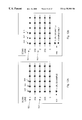
- FIG. 12B illustrates the position of unique data samples in a 4:2:2 format signal.
- FIG. 14 illustrates a plot of two signals suffering from line to line subcarrier phase differences.
- FIG. 15 illustrates a block diagram of a data decoder for use in conjunction with the second, third and fourth embodiments of the subject invention.
- FIG. 16 illustrates a block diagram of a vertical scaler and two tap comb filter configured in accordance with the second embodiment of the subject invention.
- FIG. 17 illustrates an operational flow diagram of the luminance subsystem of the vertical scaler and two tap comb filter of the second embodiment.
- FIG. 18 illustrates an operational flow diagram of the chrominance subsystem of the vertical scaler and two tap comb filter of the second embodiment.
- FIG. 19 illustrates a plot of a chrominance signal with luminance components.
- FIG. 20 illustrates a plot of a time delayed chrominance signal with luminance components.
- FIG. 21 illustrates a plot of the combination of the chrominance signal with luminance components and the time delayed chrominance signal with luminance components.
- FIG. 22 illustrates a plot of the isolated luminance components.
- FIG. 23 illustrates a block diagram of a vertical scaler and three tap comb filter configured in accordance with the third embodiment of the subject invention.
- FIG. 24 illustrates a block diagram of an adaptive output weighting system in accordance with the fifth embodiment of the subject invention.
- FIG. 25 illustrates method of operation of an adaptive output weighting system in accordance with a sixth embodiment of the subject invention.
- FIG. 26 illustrates a block diagram of an exemplary embodiment of the subject invention.
- FIG. 27 illustrates the pinouts of an exemplary embodiment of the subject invention.
- Quadrature amplitude modulation based on basic amplitude modulation
- QAM improves on the performance of basic amplitude modulation.
- the QAM technique comprises simultaneously transmitting two carrier signals, each of which are at the same frequency, but separated by a 90° phase shift.
- the mathematical form of the transmitted signal is as follows:
- a and B represent the amplitude of the two carrier signals.
- FIG. 4 graphically illustrates the relationship between two quadrature signals, A and B, each transmitted with a 90 degree phase separation 208 .
- a horizontal axis 200 represents time and a vertical axis represents amplitude 202 .
- the I component of the chrominance portion of the composite signal is transmitted on a cosine carrier wave 204
- the Q component of the chrominance portion of the composite signal is transmitted on a sine carrier wave 206
- the luminance portion of the composite signal is transmitted directly.
- the sine and cosine waves are 90 degrees out of phase.
- the luminance frequency components cluster around harmonics of the horizontal line frequency.
- the subcarrier frequency has been chosen such that the chrominance frequency components cluster around the midpoints between the harmonics of the horizontal line frequency. This has been achieved by selecting a subcarrier frequency that is 227.5 times the horizontal line frequency. Therefore, there are 227.5 subcarrier cycles per line, and the subcarrier phase at each point in one line will be 180 degrees away from the subcarrier phase at that same point in the preceding line and the following line. The advantage of this is further illustrated below in conjunction with a discussion of comb filtering.
- FIG. 5 represents the frequency content of the luminance and chrominance components of a composite signal to better illustrate the differences in frequency between these signal components.
- luminance frequency components 260 are interleaved with the chrominance frequency components 262 .
- FIG. 6 illustrates a basic comb filter.
- a composite signal arrives at input 230 and branches into a line store 232 , a first summing point 234 and a second summing point 236 .
- the line store delays the incoming composite signal for a time equivalent to the period of one line.
- the composite signal for one line is similar to the composite signal for the previous line.
- differences in phase do exist.
- the luminance portion of the composite signal is the same for both lines, but the chrominance portion of the composite signal for one line is phase shifted by 180 degrees compared to the chrominance portion of the composite signal for the previous line. This occurs because the subcarrier is phase shifted by 180 degrees relative to the previous line.
- these phase differences and the additive and subtractive properties of the feed around loop cause the unwanted portions of the chrominance and luminance signals to cancel.
- the luminance signal is provided on a line 238 and the chrominance signal provided on a line 240 .
- Another example environment of the subject invention is in video processing systems for computers.
- the subject invention separates composite video signals into the appropriate components for use in the video processing and display apparatus of a personal computer.
- the signal separation system of the present invention when presented with a composite video signal, separates the luminance and chrominance components so that each component may be encoded into a format compatible with computer video systems, such as an RGB color space.
- FIG. 8 illustrates a first embodiment of the subject invention.
- FIG. 8 illustrates a block diagram of an adaptive signal separation circuit.
- an input line 300 configured to carry a composite signal connects to a filter or filter system 302 .
- a composite signal is defined to mean a signal having unique overlapping signal components.
- the composite signal may comprise any type of composite signal, although for purposes of discussion, reference is made to a composite video signal.
- the filter system 302 separates the majority of the two or more overlapping signals that comprise the composite signal.
- the filter system 302 comprises a notch and band pass type filter.
- the modified signal separator 310 includes two outputs lines 316 , 318 connected to the luminance multiplexer 312 and chrominance multiplexer 314 as shown.
- a line difference detector 320 connects to the luminance multiplexer 312 and the chrominance multiplexer 314 .
- the operation of the adaptive signal separation system illustrated in FIG. 8 is preferably discussed in conjunction with the operational flow chart illustrated in FIG. 9 .
- the operation of the adaptive signal separation system shown in FIG. 8 comprises first receiving a composite signal at step 350 .
- the signal arriving at input line 300 comprises some form of composite or combined signal containing signal components that must be separated.
- the chrominance (C) component is output on the output line 306 .
- the band pass filtered signal is provided to the modified signal separator 310 (MSS) and the chrominance multiplexer 314 .
- the luminance signal is provided to the modified signal separator 310 and the luminance multiplexer 312 .
- the modified signal separator 310 performs modified comb filtering in accordance with the subject invention as is discussed below in conjunction with FIG. 16 .
- the modified signal separator 310 outputs a comb filtered luminance signal (Y 3 ) and a comb filtered chrominance signal (C 3 ).
- the comb filtered luminance signal (Y 3 ) and the comb filtered chrominance signal (C 3 ) comprise the complete versions of each signal.
- step 366 wherein the line difference detector 320 compares on a pixel by pixel basis the incoming video signal with a time delayed version for differences.
- each of the luminance multiplexer 312 and the chrominance multiplexer 314 is directed to output the respective signals generated by the notch and band pass filters. For example, if the color assignment as detected between pixels is changing, or if there is a change in rumination between pixels, then the preferred signal separation technique is notch and band pass filtering.
- the line difference detector 320 determines a substantial change in pixel values in a line to line comparison, then it instructs the multiplexers 312 , 314 to output on lines 322 , 324 the output of the filter system 302 . Conversely, if the line difference detector 320 determines no change in pixel value in a line to line comparison, or if the size of the change is below a threshold level, it instructs the multiplexers 312 , 314 to output on lines 322 , 324 the output of the modified signal separator 310 .
- FIG. 10 illustrates a detailed block diagram of the modified signal separator 310 .
- the modified signal separator 310 receives a notch filtered luminance (Y) input 304 and a band pass filtered chrominance (C) input 306 .
- the inputs 304 , 306 are modulated.
- the information is generally imposed on a subcarrier signal to facilitate transmission.
- the notch filtered Y input 304 is coupled to a summer unit 410 , the function of which will be discussed in greater detail below.
- the band pass filtered chrominance input 306 is coupled to a chrominance demodulator 400 .
- the demodulator 400 reverses the effect of modulation, thereby eliminating the controlled frequency variation and phase and/or amplitude variation of a carrier wave.
- the incoming chrominance signal is multiplied by the cosine and sine signals arriving from the subcarrier generator because an NTSC chrominance signal is represented by
- the two times subcarrier frequency components (2wT) are removed by low pass filtering resulting in the I and Q signals being recovered.
- NTSC NTSC
- NTSC NTSC
- PAL PAL
- a decimator 402 is a video processing device that reduces the amount of digital information that represents an image.
- FIGS. 12A and 12B illustrates the effect of decimation on a video image in relation to the storage requirements for the image.
- two common video formats are the 4:4:4 YCrCb format and the 4:2:2 YCrCb format.
- the Cr and Cb format is simply a different color space representation of the chrominance signal and, while not the focus of the present discussion, is briefly discussed for purposes of understanding.
- Color space is a term common to video processing and simply denotes a mathematical representation for a color.
- Television decoders utilize the mathematical color representation to generate the various colors in the displayed image.
- the YCrCb color space is the color space defined by Recommendation ITU-R BT.601.
- U-V color space is the mathematical format used to define color in the NTSC standard.
- the Cr and Cb components are color difference signals that, when presented together, represent a color. These values can be thought of as scaled versions of U and V in the YUV color space.
- 4:4:4 format and the 4:2:2 format.
- These format representations indicate the number of samples that represent four video pixels.
- X:Y:Z the X position represents the number of data samples that represent the luminance information for four pixels.
- the Y position represents the number of data samples that represent four pixels of Cr data while the Z position represents the number of samples that represent four pixels of the Cb data.
- each pixel is represented by an independent Y, a Cr, and a Cb value. This is illustrated in FIG. 12A.
- a portion of the display comprising a first line 500 and a second line 502 is shown.
- the first line 500 includes pixels 504 , 505 and 508 .
- each pixel is represented by an eight bit Y sample value, an eight bit Cr sample value and an eight bit Cb sample value.
- the 4:2:2 format is illustrated in FIG. 12B where, in relation to FIG. 12A, like elements are referenced with like reference numerals.
- an independent sample value for each of Y, Cr and Cb represent the pixel 510 .
- pixel 512 only has an independent sample value for the luminance component (Y).
- the Cr and Cb sample values must be derived from other Cr and Cb values in the image data. This pattern repeats as shown in all the lines in the display.
- the sample values for Cr and Cb for pixel 512 are obtained using interpolation between the corresponding values of pixels 510 and 513 .
- Decimation to a 4:2:2 format is performed in several ways.
- One method is to simply discard the unwanted samples. However, this method may introduce image artifacts in the video signal.
- An alternative method is to use a decimation filter which reduces artifacts to an acceptable level by smoothing in areas of the image containing fine or detailed image information or by smoothing in areas of the signal that represent movement in the image.
- Decimation filters provide excellent results in areas where the color information is unchanging from one sample to the next.
- the output of the decimator 402 is coupled to a comb filter 404 .
- Comb filters will be discussed in greater detail in conjunction with FIG. 16 .
- Comb filters take advantage of the difference in phase shift from one line to the next line in the chrominance signal versus that in the luminance signal to remove unwanted portions of the luminance information from the chrominance signal.
- the subcarrier frequency has been selected such that its phase shifts by 180 degrees from one line to the next line.
- this subcarrier is used to modulate the I and Q components, it produces a chrominance signal that is 180 degrees phase shifted from one line to the next line, assuming the I and Q components are the same for the two lines.
- This modulated chrominance signal is combined with the luminance signal, which is not modulated and has no phase shift from one line to the next line, to produce the composite signal.
- the band pass filtered data which contains chrominance and luminance components, is demodulated, and the line to line phase shift is eliminated from the chrominance components, but introduced into the luminance components. It is this difference in phase shift characteristics that enables comb filters to be used to improve Y/C separation.
- the operation of the comb filter is discussed in great detail in conjunction with FIGS. 17 through 18.
- the comb filter 404 includes two outputs.
- the first output comprises a combed chrominance signal on signal line 318 .
- the chrominance signal C 3 on line 318 contains only chrominance information because the comb filter removes or at least substantially removes the luminance components in accordance with the principles of comb filters, discussed in great detail below.
- the second output of the comb filter 404 on signal line 405 connects to an interpolator 406 .
- the signal on line 405 contains the luminance components missing from signal Y 2 on line 304 , and combed from the chrominance signal C 2 .
- the combed luminance components on line 405 are eventually combined with the luminance signal Y 2 on line 304 .
- the output of the comb filter 404 is coupled to an interpolator 406 .
- the interpolator 406 reverses, or at least substantially reverses, the effects of the decimator 402 , thereby restoring the video signal to a 4:4:4 format.
- the interpolation averages adjacent pixel sample values to restore the information that was discarded or filtered by the decimator 402 . Interpolation to a 4:4:4 format is necessary so that the luminance components may be accurately restored to the luminance signal.
- the output of the interpolator 406 is coupled to a modulator 408 .
- the modulator 408 reverses or at least substantially reverses the effects of the demodulator 400 thereby modulating the combed luminance components to the subcarrier frequency.
- the luminance component riding on the chrominance signal was originally centered at 3.58 MHz.
- the demodulator 400 removed or at least substantially removed the effect of the 3.58 MHz sub-carrier.
- the signal is re-modulated to 3.58 MHz.
- Modulation techniques for video signals are known by those of ordinary skill in the art and accordingly are not discussed in great detail herein. However it should be noted that the proper phase relationship and timing with the sub-carrier is maintained to ensure proper synchronization.
- the output of the modulator 408 is coupled to summing point 410 , which is configured to add the signal arriving from the modulator 408 to the notch filtered luminance signal (Y 2 ) arriving over line 304 .
- the summing point 410 provides an output (Y 3 ) on a line 316 that represents the total luminance signal.
- the signal Y 3 is the complete luminance signal.
- FIG. 13 illustrates an operational flow diagram of the modified signal separator as illustrated in FIG. 10 .
- the modified signal separator 310 receives at its inputs 304 , 306 the notch filtered luminance signal, denoted Y 2 , and the band pass filter chrominance signal, denoted C 2 .
- the luminance value is forwarded to a summing point 410 and the chrominance value is forwarded to the demodulator 400 .
- the operation of the summing point 410 is discussed in more detail below.
- the demodulator 400 eliminates, or at least substantially eliminates, the carrier signal from the incoming chrominance information, thereby restoring information to a demodulated state.
- the demodulated chrominance signal enters the decimator 402 .
- the decimator 402 operates to reduce the number of bits utilized to store the chrominance signal.
- every four pixels of video is comprised of four luminance samples and two chrominance samples. Accordingly, to store four pixels of video in a 4:2:2 format, 32 bits of luminance information is stored (4 luminance samples ⁇ 8 bits each), 32 bits of chrominance information (2 Cr samples ⁇ 8 bits each), and (2 Cb samples ⁇ 8 bits each) is stored. This equates to 64 bits of memory space required to store the chrominance information and luminance information in a 4:2:2 format. The advantages of reducing the storage requirements for the video information will become apparent in the following discussion for comb filters.
- the operation forwards the 4:2:2 format chrominance information to the comb filter 404 .
- the comb filter utilizes line stores in combination with summing points to manipulate the chrominance signal to isolate or at least substantially isolate the luminance components from the chrominance signal. Upon isolation, these luminance components are subtracted from the chrominance signal to provide the combed chrominance signal (C 3 ) that does not contain unwanted luminance components.
- step 558 the operation forwards the comb filtered luminance components to an interpolator 406 .
- the interpolator restores the format of the comb filtered luminance components to a 4:4:4 format. It is necessary to restore the format of the comb filtered luminance components, such as those on line 405 in FIG. 10, to the format of the notch filtered luminance signal (Y 2 ) prior to combination.
- step 562 the modulator 408 re-modulates the combed luminance components to the subcarrier frequency so that the combed luminance components are at the proper frequency.
- the 3.58 MHz subcarrier frequency is added to the frequency of the luminance components.
- the operation combines the comb filtered luminance components with the luminance signal (Y 2 ) in summing point 410 .
- This process restores the luminance components that were removed from the composite signal by the notch filter to provide a restored or complete luminance signal.
- the restored luminance signal is denoted Y 3 .
- the operation outputs the complete luminance signal (Y 3 ) on a line 316 . This completes the operational process of the modified comb filter.
- a signal separation system configured in accordance with the subject invention more accurately separates the signals by more completely recreating the luminance signal.
- Systems operating in accordance with one embodiment of the subject invention restore or at least substantially restore the comb filtered luminance components that are missing from the notch filtered luminance signal (Y 2 ).
- reducing the format of the signal prior to comb filtering reduces the memory requirements of each line store in the comb filter. In comb filters having greater than one line store, memory requirements are further reduced.
- systems that operate in accordance with the subject invention and that demodulate the signal prior to comb filtering significantly reduce distortion arising from line-to-line subcarrier phase differences.
- Line-to-line subcarrier phase differences are best explained with reference to FIG. 14, which illustrates a plot of two band pass filtered signals that are in a modulated state, one of which is suffering from line-to-line subcarrier phase differences.
- An in-phase signal 570 is not suffering from line-to-line subcarrier phase distortion and as such has a zero value as it crosses the horizontal axis.
- an out-of-phase signal 571 that is offset from the in-phase signal 570 .
- the in-phase signal 570 is delayed by the line store in a comb filter and combined with non-delayed out-of-phase signal 571 , the two signals do not completely cancel due to the phase differences. This leads to distortion and artifacts in the video image. This is a problem with systems that do not adopt the principles of the subject invention.
- Systems operating in accordance with the subject invention demodulate the chrominance signal prior to comb filtering.
- Demodulating the chrominance signal eliminates the subcarrier modulation from the chrominance signal.
- the line-to-line phase differences are advantageously also eliminated from the chrominance information.
- the subject invention overcomes the problems of distortion caused by subcarrier line-to-line phase differences.
- FIG. 15 illustrates one configuration of a video data decoder path as found in video decoders adopting the signal separation techniques of the subject invention.
- This decoder is provided by way of example only and the scope of the subject invention is not limited to the configuration shown.
- the data decoder provides the supporting circuitry to facilitate video signal separation in accordance with the subject invention.
- the data decoder shown in FIG. 15 is configured for operation with signals following the NTSC standard. It is contemplated that the principles of the present invention could be applied to other video formats including but not limited to PAL and SECAM.
- FIG. 23 illustrates a third example embodiment, including the componentry and configuration for the block labeled vertical scaler and comb filter. This embodiment interfaces with the hardware of the data decoder shown in FIG. 15 .
- the design of the notch filter 702 removes or at least substantially removes signal components having a frequency between 2.5 to 4.5 MHz.
- the signal portion which is allowed to pass through the notch filter 702 contains luminance information.
- the notch filter also removes portions of the signal within this frequency range that contain luminance information.
- the band pass filter 704 allows to pass portions of the composite signal having frequency components generally between 2.5 to 4.5 MHz. This portion of the composite signal contains primarily chrominance information, but as previously discussed, this portion or band of the signal allowed to pass also contains luminance information.
- the band pass filter output is coupled to a chrominance demodulator 706 .
- the chrominance demodulator 706 receives sine and cosine modulated signals at the subcarrier frequency from a subcarrier signal generator 708 .
- the demodulator 706 utilizes these subcarrier signals to demodulate the chrominance signal.
- the demodulator separates or at least substantially separates the chrominance signal into I and Q components.
- the output of the demodulator 706 is coupled to a format conversion module 710 .
- the format conversion module 710 of the second embodiment changes the signal format from a 4:4:4 format to a 4:2:2 format. This advantageously reduces the storage requirements of the signal. Reducing the format to a 4:2:2 format does not result in data loss or reduced resolution because the signal is demodulated prior to format conversion. Demodulating the signal reduces the highest frequency of the signal and because the highest frequency is reduced, the sampling rate may also be reduced without data loss. This principle is exemplified by the Nyquist sampling rate theory that states the sampling rate need only be twice the highest frequency of the sampled signal in order to accurately recreate the signal. This relationship is expressed below:
- the horizontal scaler outputs 714 , 716 are coupled to a vertical scaler and comb filter 718 .
- the vertical scaler and comb filter 718 also receives as input the sine and cosine subcarrier signals from the signal generator 708 .
- the vertical scaler and comb filter 718 receives as a first input the horizontally scaled, notch filtered luminance signal 714 and as a second input the horizontally scaled, demodulated band pass filtered chrominance signal 716 in a reduced memory format.
- FIG. 16 a second embodiment of the vertical scaler and comb filter 718 is provided.
- the vertical scaler and comb filter 718 is separated into a luminance subsystem and a chrominance subsystem. Each is discussed below.
- the horizontally scaled luminance signal is provided to a line store 754 .
- the line store 754 stores the input for a time equivalent to one line trace period, i.e. the time it takes to trace one line on a display, before providing its output to a vertical luminance scaler 756 .
- One configuration of a line store comprises a series of registers configured to store the data samples until prompted by a control signal.
- the line store comprises computer memory accessed with a software pointer.
- the vertical luminance scaler 756 also receives as an input the undelayed horizontally scaled luminance signal on line 750 .
- the vertical luminance scaler interpolates the delayed and undelayed luminance signals to adjust the vertical dimension of the luminance signal.
- a luminance summing point 762 is coupled to the output of the vertical luminance scaler 756 over line 760 .
- the signal on line 760 comprises a luminance signal that is missing certain luminance components due to notch filtering. For purposes of discussion, this signal is designated (Y ⁇ Y′) where Y is the complete luminance signal and Y′ represent the luminance components missing from the luminance signal.
- a luminance output line 798 provides to the output of the luminance summing point 762 .
- the line store 770 delays the signal for the period of a line trace.
- the output of the line store 770 connects to a second multiplier 772 .
- Both multipliers 772 , 774 reduce their received signals by one-half or about one-half through a multiplication process. This may be implemented in various ways, including but not limited to a simple shift of the data one bit at a time.
- a first comb filter summing point 780 is coupled to the output of the first multiplier 774 and the output of a second multiplier 772 .
- the first comb filter summing point 780 adds the two inputs and provides this combined signal on a line 786 .
- This signal comprises the combed chrominance information (I/Q) and is provided at an output line 800 .
- Multipliers 772 and 774 and adders 780 and 784 therefore process both I and Q data. If the I and Q data is not multiplexed, then those four components must be duplicated so that the I data and the Q data can each have dedicated multipliers and adders.
- a modulator 792 is coupled to the outputs of the second format conversion module 790 and re-modulates the signal using the appropriate sine and cosine signals at the subcarrier frequency.
- a summing point 794 connects to the dual outputs of the modulator 792 to combine the outputs of the modulator into a single signal on line 796 .
- the luminance summing point 762 is coupled via line 796 to the output of the summing point 794 .
- Output line 798 is coupled to the output of the luminance summing point 762 and carries the combined luminance signal.
- FIGS. 17 and 18 illustrate an operational flow diagram of the vertical scaler and two tap comb filter as shown in FIG. 16 .
- FIG. 17 illustrates the operation of the luminance subsystem
- FIG. 18 illustrates the operation of the chrominance subsystem.
- the luminance subsystem receives the horizontally scaled luminance signal, denoted as (Y ⁇ Y′).
- the operation stores one line of video for vertical luminance scaling.
- the operation performs vertical luminance scaling to adjust the vertical dimensions of the video image.
- the luminance subsystem obtains the combed luminance components, denoted as Y′, from the chrominance subsystem, the operation of which is presented in FIG. 18 .
- the operation combines or adds the output of the vertical scaler, denoted Y ⁇ Y′, with the input from the chrominance subsystem, denoted Y′.
- the following equation represents the combination.
- Y represents the complete luminance signal.
- the complete luminance signal Y is output on a line 798 .
- FIG. 18 illustrates an operational flow diagram of the chrominance subsystem.
- the chrominance subsystem receives the horizontally scaled chrominance signal, which for purposes of discussion, is denoted (C t +Y t ′), which is composed of I and Q components, [(I t +Y I ′), (Q t +Y Q ′)].
- C t +Y t ′ An example of this (C t +Y t ′) signal is shown in FIG. 19 .
- the C t portion is signal 912 while the Y′ portion is denoted as signal 914 .
- the signal C t +Y′ t contains the chrominance signal C t and a portion of the luminance signal Y′ t riding on the chrominance signal.
- the signal component 1 ⁇ 2C t overlaps in-phase with the 1 ⁇ 2C t ⁇ 1 component to form C t .
- the signal component 1 ⁇ 2Y′ t is 180 degrees out of phase with the component 1 ⁇ 2Y′t ⁇ 1 causing the Y′ t component to cancel with the Y′ t ⁇ 1 component.
- the resulting signal is purely or at least substantially the chrominance information, denoted C t .
- the pure or at least substantially pure chrominance signal C t is output on a line 800 .
- the original chrominance signal 912 and the luminance information 916 are added to the negative of the pure chrominance signal 917 .
- This in effect subtracts the pure chrominance C t signal from the combined signal (C t +Y′ t ), an operation which leaves only the luminance portion of the signal (Y′ t ).
- FIG. 22 illustrates the luminance component Y′ t , shown as line 916 , that has successfully been isolated.
- the operation re-modulates each component of Y′ t (I) and Y′ t (Q) to the carrier frequency centered at 3.58 MHz, the general center frequency of the notch filter.
- This advantageously aligns at the proper frequency the combed Y′ t components of the luminance information with the original luminance signal (Y t ⁇ Y′ t ). Absent the re-modulating alignment process, the combed luminance signal Y′ t would, when combined in a step 938 , not be combined at the right frequency position in the luminance signal.
- the operation combines in modulator summing point 794 the Y′ t (I) and Y′ t (Q) components to form a remodulated Y′ t signal.
- the combed luminance components Y′ t are combined with the original luminance signal (Y t ⁇ Y′ t ).
- the following equation represents this combination.
- FIG. 23 illustrates a third embodiment of the vertical scaler and comb filter configured with a three tap comb filter.
- like elements are numbered with like reference numerals.
- a three tap comb filter replaces the two tap comb filter of FIG. 16 .
- the configuration of the three tap comb filter is now discussed.
- the input line 752 is coupled to a first line store 820 and a first 1 ⁇ 4 multiplier 822 .
- the 1 ⁇ 4 multiplier 822 reduces the amplitude of the received signal by one quarter and provides it to the first comb filter summing point 780 .
- the second line store 830 delays the signal on line 824 a time equal to a line trace and provides the twice delayed output on a line 831 to a second 1 ⁇ 4 multiplier unit 834 .
- the output of the second 1 ⁇ 4 multiplier unit 834 connects to the first comb filter summing point 780 .
- the subject invention is embodied without the format conversion module identified as element 710 (FIG. 15) and 790 (FIG. 16 ).
- Configuring the subject invention without the format conversion module advantageously reduces the cost of the system by eliminating this componentry. Absent the format conversion module 710 , 790 , the separation system does not enjoy the memory saving attributes associated with presenting a signal sampled at a lower sampling rate to the line stores in the comb filter. However, inclusion of the format conversion module is not a requisite to practice the subject invention.
- a line difference detector 950 taps onto line 752 and line 831 to obtain the signals thereon.
- the line difference detector 950 compares the signals on these two lines on a pixel-by-pixel basis for differences. It is contemplated that an evaluation on other than a pixel-by-pixel basis may be undertaken.
- the pixels subject to comparison are separated by two lines or a multiple of two lines, to ensure that the subcarrier phase is the same for both pixels.
- the chrominance portion of the signal has been demodulated (block 706 , FIG. 15 ). Because the chrominance signal includes certain luminance components (C t +Y′ t ) in a demodulated state, the chrominance signals, when compared line-to-line, are in-phase while the luminance component riding thereon are out of phase between adjacent lines by 180 degrees.
- the difference detector 950 must compare non-adjacent video lines. Stated another way, the difference detector 950 must compare pixels at C t to pixels at C t ⁇ 2 .
- the line difference detector 950 also performs mathematical manipulation to generate a value representing one minus the Ycoeff (1 ⁇ Ycoeff) and one minus the Ccoeff (1 ⁇ Ccoeff). Thus, as the Ycoeff increases the value for (1 ⁇ Ycoeff) decreases.
- a multiplier 960 is coupled to the Ycoeff output via a line 952 and to the notch filter output (Y t ⁇ Y′ t ) on line 750 .
- the multiplier 960 multiplies the notch filter output (Y t ⁇ Y′ t ) by the value of the Ycoeff and outputs this value to a summing point 970 .
- a multiplier 962 is coupled to the (1 ⁇ Ycoeff) output via a line 954 and to the complete luminance output Y t on line 798 .
- the multiplier 960 multiplies the comb filtered Y output (Y t ) by the value of (1 ⁇ Ycoeff) and outputs this value to a summing point 970 .
- the summing point 970 adds each of the weighted portions of the inputs provided from the multipliers 960 , 962 and outputs the sum on the luminance adaptive output line 974 .
- This is the luminance signal of the adaptive signal separation system of the fifth embodiment.
- a multiplier 964 is coupled to the Ccoeff output via a line 956 and to the band pass filtered chrominance output (C t +Y′ t ) from line 752 .
- the multiplier 964 multiplies the band pass filtered chrominance output (C t +Y′ t ) by the value of the Ccoeff. and outputs this value to a summing point 972 .
- a multiplier 966 is coupled to the (1 ⁇ Ccoeff) output via a line 958 and to the comb filtered chrominance output C t on line 800 .
- the multiplier 966 multiplies the comb filtered chrominance output C t by the value of (1 ⁇ Ccoeff) and outputs this value to a summing point 972 .
- the summing point 972 adds each of the weighted portions of the inputs provided from the multipliers 964 , 966 and outputs the sum on the chrominance adaptive output line 976 .
- This is the chrominance signal of the adaptive signal separation system of the fifth embodiment.
- the adaptively adjusted luminance output on line 974 and the adaptively adjusted chrominance output on line 976 represent the dynamically adjusted output of 1) the notch and band pass filtered composite signal and 2) the modified comb filter operating in accordance with the subject invention.
- this circuit dynamically selects, on a pixel by pixel basis or on a line by line basis, the amount of 1) a signal separated using basic notch and band pass filtering and 2) a signal separated using the subject invention's comb filtering process.
- the line difference detector 950 finds a difference between compared pixels, it increases the value of the Ycoeff. and the Ccoeff. This in turn causes the values of 1 ⁇ Ycoeff and 1 ⁇ Ccoeff to decrease.
- the multipliers 960 , 962 , 964 , 966 provide greater weight to the signals obtained from basic notch and band pass filtering and less weight to the signals obtained from the comb filter.
- the summing points 970 , 972 form the final output on lines 974 and 976 based on the more heavily weighted signals from notch and band pass filtering.
- the adaptive system of the fifth embodiment predominately utilizes the notch and band pass filtered outputs. Because of the drawbacks of comb filtering in relation to video signals that represent motion or color changes, the system advantageously adjusts the output thereof as appropriate, and more specifically, the filtering method used to form the output.
- the following table provides a more complete but general illustration of this point:
- the signal selection or signal weighting performed in relation to the selection of the filtering method utilized to form the output is selected based on a threshold value, in contrast to a sliding scale as employed in the fifth embodiment.
- FIG. 25 illustrates a method of operation for adjustable threshold adaptive filtering.
- the adaptive system obtains a chrominance threshold value (Ctv).
- the Ctv represents the threshold value that marks the jump point at which the system changes the filtering method for the chrominance signal.
- the system obtains a luminance threshold value (Ytv).
- Ytv represents the threshold value that marks the jump point at which the system changes the filtering method for the luminance signal.
- the system obtains the Ctv and Ytv from a user input such as from a computerized user interface or manual adjustment.
- the Ctv and Ytv values are permanently configured for a particular system.
- the system detects the change or delta (a) in the chrominance value between the input pixel one line prior to the current output pixel and the input pixel one line after the current output pixel.
- the change in chrominance is represented (C1 ⁇ C2).
- the chrominance value for each pixel is composed of two components, I and Q, so the difference between two chrominance value s is also composed of two components. Since the chrominance value for the input pixels to the comb filter contain the chrominance as well as some of the luminance for that pixel, changes in that chrominance value will reflect changes in the chrominance as well as changes in the luminance that passed in to the chrominance channel.
- the change in chrominance value (C1 ⁇ C2) is compared to the threshold value Ytv.
- This comparison can be performed in various ways including but not limited to comparing the vector length, or comparing the sum of the vector components, or comparing each component of the vector separately.
- step 1008 the system outputs the luminance signal from the filter that is optimized for changes in chrominance value that are above Ytv.
- step 1010 the system outputs the luminance signal from the filter that is optimized for changes in chrominance value that is at or below Ytv.
- the adaptive system utilizes tile output from the notch filter because in instances of change or at least significant change in chrominance values, which may represent changes in chrominance or luminance, the notch filtering method is superior over comb filtering.
- the adaptive system utilizes the output from the comb filter because, in instances when there is little change in chrominance values, comb filtering provides superior results over notch filtering.
- Ytv is selected to optimize the output and may conveniently be adjusted by the user based on personal preference.
- step 1028 the system progresses to decision step 1028 , discussed below in greater detail.
- the change in chrominance value (C1 ⁇ C2) is compared to the threshold value Ctv.
- This comparison could be performed in various ways including but not limited to comparing the vector length, or comparing the sum of the vector components, or comparing each component of the vector separately.
- step 1026 the system outputs the chrominance signal from the filter that is optimized for changes in chrominance value that are above Ctv.
- the system progresses to decision step 1028 .
- decision step 1028 the system queries the Ctv values and the Ytv values to evaluate whether the threshold values have changed.
- One example implementation of the subject invention is embodied in a video capture processor and scaler for television and VCR input.
- the subject invention is embodied in the Bt835 VideoStreaMTM III Decoder available from Conexant Systems, Inc. of San Diego, Calif., formerly Rockwell Semiconductor Systems.
- the Bt835 is a high quality single chip composite NTSC/PAL/SECAM video and S-video decoder having low power consumption requirements.
- the subject invention embodied therein integrates with a 3-line adaptive comb filter in accordance with the principles of the subject invention to overcome the disadvantages of traditional comb filter artifacts.
- Input port 600 connects to an analog video multiplexer 602 .
- the analog video multiplexer provides means to simultaneously receive input from multiple video sources, such as a receiver, VCR, camcorder, or antenna.
- the output of the multiplexer 602 connects to a first 40 MHz analog to digital converter 608 .
- the 40 MHz analog to digital converter 608 (A/D) converts the analog input into a digital output.
- the output of the 40 MHz A/D converter 608 connects to a decimation low pass filter 611 .
- a second 40 MHz analog to digital converter 610 obtains an analog chrominance signal from a C input, and, after conversion to a digital format, outputs the digital signal to the decimation low pass filter 611 .
- the decimation low pass filter 611 performs two times decimation on the outputs of the over-sampled A/D converters 608 , 610 so that a simpler anti-aliasing filter may be utilized in the analog domain.
- the output of the decimation low pass filter 611 connects to a phase lock and clock generation module 604 , a 3-line adaptive luma-chroma separation and chroma demodulation module 606 , and an automatic gain control (AGC) 652 .
- the phase lock and clock generation module 604 synchronizes the phase of the video signal and generates appropriate clock signals for operation of the digital circuitry.
- the 3-line adaptive luma-chroma separation and chroma demodulation module 606 separates the luminance and chrominance components from the received signal by adaptively utilizing either of a notch and band pass filter combination or a 3 tap comb filter depending on the attributes of the received signal.
- the 3-line adaptive luma-chroma separation and chroma demodulation module 606 also includes a chroma demodulation capability to demodulate the chrominance portion of the signal in accordance with the subject invention.
- the combed portions of the luminance signal are re-formatted, re-modulated and combined with the notch filtered luminance signal to prevent unwanted artifacts in the output and provide a more robust and complete luminance signal.
- the AGC 652 enables the Bt835 to compensate for reduced amplitude in the analog circuit received at input 600 .
- the output of the phase lock and clock generation module 604 connects to a video timing unit 620 .
- the video timing unit detects sync pulses in the incoming signal and generates internal and external timing signals to insure accurate timing of the video output.
- the output of the 3-line adaptive luma-chroma separation and chroma demodulation module 606 connects to a spatial and temporal scaling module 622 that is responsible for adjusting the size and timing of the video display.
- the temporal scaling module 622 also receives input from a digital video input 624 in conjunction with a digital input video clock and timing input 626 . These inputs provide means for the Bt835 to receive digital video input.
- the outputs of the video timing unit 620 and the spatial and temporal scaling module 622 connect to an output formatting module 630 .
- the output formatting module 630 manipulates the image signal to a format compatible for transmission to a display monitor or video processing card.
- the output formatting module 630 includes a 16 bit digital video output 634 and a video timing output 632 . These outputs 634 , 632 connect to a display or video processing card.
- An output control line 640 provides input to the output formatting module 630 to partially control the output of the output formatting module 630 .
Landscapes
- Engineering & Computer Science (AREA)
- Multimedia (AREA)
- Signal Processing (AREA)
- Processing Of Color Television Signals (AREA)
Abstract
Description
| Ycoeff. | 1-Ycoeff. | |||
| Line | and | and | Predominate | |
| Video Image | Difference | Ccoeff. | 1-Ccoeff | Separation |
| Properties | Detector | Values | Values | Method |
| motion or | Difference | Increase | Decreases | Notch and Band |
| color change | Detected | Pass Filtering | ||
| no motion or | No | Decrease | Increases | Comb Filtering |
| color change | Difference | |||
| Detected | ||||
| moderate | Moderate | set to | equates to | Combination of |
| motion | Difference | about .5 | about .5 | Both Notch and |
| or color | Detected | Band Pass and | ||
| change | Comb Filtering | |||
Claims (22)
Priority Applications (1)
| Application Number | Priority Date | Filing Date | Title |
|---|---|---|---|
| US09/244,642 US6175389B1 (en) | 1999-02-04 | 1999-02-04 | Comb filtered signal separation |
Applications Claiming Priority (1)
| Application Number | Priority Date | Filing Date | Title |
|---|---|---|---|
| US09/244,642 US6175389B1 (en) | 1999-02-04 | 1999-02-04 | Comb filtered signal separation |
Publications (1)
| Publication Number | Publication Date |
|---|---|
| US6175389B1 true US6175389B1 (en) | 2001-01-16 |
Family
ID=22923567
Family Applications (1)
| Application Number | Title | Priority Date | Filing Date |
|---|---|---|---|
| US09/244,642 Expired - Lifetime US6175389B1 (en) | 1999-02-04 | 1999-02-04 | Comb filtered signal separation |
Country Status (1)
| Country | Link |
|---|---|
| US (1) | US6175389B1 (en) |
Cited By (25)
| Publication number | Priority date | Publication date | Assignee | Title |
|---|---|---|---|---|
| US6356145B1 (en) * | 1999-12-27 | 2002-03-12 | Mitsubishi Denki Kabushiki Kaisha | Demodulator circuit which demodulates a signal without any restriction from a clock signal |
| US20020079989A1 (en) * | 2000-11-02 | 2002-06-27 | Michio Kadota | End surface reflection type surface acoustic wave apparatus |
| US20020080268A1 (en) * | 2000-12-22 | 2002-06-27 | Willis Donald Henry | Method and system for MPEG chroma de-interlacing |
| US6529244B1 (en) * | 1999-12-22 | 2003-03-04 | International Business Machines Corporation | Digital video decode system with OSD processor for converting graphics data in 4:4:4 format to 4:2:2 format by mathematically combining chrominance values |
| US20030108123A1 (en) * | 2001-12-10 | 2003-06-12 | Kroeger Brian William | AM digital audio broadcasting with analog signal pre-compensation |
| US20060176406A1 (en) * | 2005-01-13 | 2006-08-10 | Samsung Electronics Co., Ltd. | Digital video signal processing apparatus and method for frame-based adaptive temporal and spatial Y/C separation |
| US7161989B1 (en) | 2003-03-29 | 2007-01-09 | Wideband Semiconductors, Inc. | CIC qam modulator |
| US7167213B1 (en) * | 2003-12-30 | 2007-01-23 | Conexant Systems, Inc. | Comb filter design for separating luminance and chrominance in video signals |
| US7227587B2 (en) * | 2003-03-05 | 2007-06-05 | Broadcom Corporation | System and method for three dimensional comb filtering |
| US7304688B1 (en) * | 2003-05-20 | 2007-12-04 | Pixelworks, Inc. | Adaptive Y/C separator |
| US7365796B1 (en) | 2003-05-20 | 2008-04-29 | Pixelworks, Inc. | System and method for video signal decoding using digital signal processing |
| US7420625B1 (en) | 2003-05-20 | 2008-09-02 | Pixelworks, Inc. | Fuzzy logic based adaptive Y/C separation system and method |
| US7430020B1 (en) | 2005-07-07 | 2008-09-30 | Ess Technology, Inc. | Separation of composite video signals using dot crawl detector |
| US20080285768A1 (en) * | 2005-04-18 | 2008-11-20 | Larsen Soren M | Method and System for Modifying and Audio Signal, and Filter System for Modifying an Electrical Signal |
| US20080310749A1 (en) * | 2007-06-15 | 2008-12-18 | Mstar Semiconductor, Inc. | Method and apparatus for image processing |
| US7532254B1 (en) | 2003-05-20 | 2009-05-12 | Pixelworks, Inc. | Comb filter system and method |
| US7605867B1 (en) | 2003-05-20 | 2009-10-20 | Pixelworks, Inc. | Method and apparatus for correction of time base errors |
| US20100045871A1 (en) * | 2006-04-07 | 2010-02-25 | Ati Technologies, Inc. | Video luminance chrominance separation |
| US7701512B1 (en) | 2003-05-20 | 2010-04-20 | Pixelworks, Inc. | System and method for improved horizontal and vertical sync pulse detection and processing |
| US20100165209A1 (en) * | 2008-12-31 | 2010-07-01 | Stmicroelectronics Asia Pacific Pte Ltd | System and method for phase motion detection for YC separation |
| CN101540922B (en) * | 2008-03-18 | 2010-08-18 | 联发科技股份有限公司 | Decoder and method for separating luminance and chrominance information from composite video signal |
| US20100225806A1 (en) * | 2009-03-06 | 2010-09-09 | Wintek Corporation | Image Processing Method |
| US8553155B2 (en) * | 2003-03-05 | 2013-10-08 | Broadcom Corporation | System and method for three dimensional comb filtering |
| US8665985B1 (en) * | 2013-05-29 | 2014-03-04 | Gregory Hubert Piesinger | Secondary communication signal method and apparatus |
| WO2024169446A1 (en) * | 2023-02-17 | 2024-08-22 | 华为技术有限公司 | Frequency difference adjuster, frequency difference adjustment method, laser generating apparatus, and electronic device |
Citations (7)
| Publication number | Priority date | Publication date | Assignee | Title |
|---|---|---|---|---|
| US4355333A (en) * | 1980-04-28 | 1982-10-19 | Sony Corporation | Video signal processing circuit with comb filter |
| US4470069A (en) * | 1982-08-04 | 1984-09-04 | Rca Corporation | Reduced data rate digital comb filter |
| US4532542A (en) * | 1983-04-01 | 1985-07-30 | Tektronix, Inc. | Comb filters |
| US5161006A (en) * | 1990-07-26 | 1992-11-03 | Massachusetts Institute Of Technology | Method for separating chrominance and luminance components of a television signal |
| US5231476A (en) * | 1990-11-05 | 1993-07-27 | Kabushiki Kaisha Toshiba | Luminance/chrominance separating apparatus |
| US5457501A (en) * | 1992-04-23 | 1995-10-10 | Goldstar Co., Ltd. | Spectrum distribution adaptive luminance/color signal separating device |
| US5475445A (en) * | 1990-04-03 | 1995-12-12 | Mitsubishi Denki Kabushiki Kaisha | Motion adaptive luminance signal and color signal separation filter |
-
1999
- 1999-02-04 US US09/244,642 patent/US6175389B1/en not_active Expired - Lifetime
Patent Citations (7)
| Publication number | Priority date | Publication date | Assignee | Title |
|---|---|---|---|---|
| US4355333A (en) * | 1980-04-28 | 1982-10-19 | Sony Corporation | Video signal processing circuit with comb filter |
| US4470069A (en) * | 1982-08-04 | 1984-09-04 | Rca Corporation | Reduced data rate digital comb filter |
| US4532542A (en) * | 1983-04-01 | 1985-07-30 | Tektronix, Inc. | Comb filters |
| US5475445A (en) * | 1990-04-03 | 1995-12-12 | Mitsubishi Denki Kabushiki Kaisha | Motion adaptive luminance signal and color signal separation filter |
| US5161006A (en) * | 1990-07-26 | 1992-11-03 | Massachusetts Institute Of Technology | Method for separating chrominance and luminance components of a television signal |
| US5231476A (en) * | 1990-11-05 | 1993-07-27 | Kabushiki Kaisha Toshiba | Luminance/chrominance separating apparatus |
| US5457501A (en) * | 1992-04-23 | 1995-10-10 | Goldstar Co., Ltd. | Spectrum distribution adaptive luminance/color signal separating device |
Non-Patent Citations (2)
| Title |
|---|
| Bradford, Steven, "A Simplified Guide to the NTSC Video Signal," NTSC Video Signal Basics, http://www.seanet.com/users/bradford/ntscvideo.html. |
| Rogers, Greg, "Video Signal Formats," Video Signal Formats, http:cybertheater.com/Tech-Archive/YC-Comp-Format/yc-comp-format.html. |
Cited By (38)
| Publication number | Priority date | Publication date | Assignee | Title |
|---|---|---|---|---|
| US6529244B1 (en) * | 1999-12-22 | 2003-03-04 | International Business Machines Corporation | Digital video decode system with OSD processor for converting graphics data in 4:4:4 format to 4:2:2 format by mathematically combining chrominance values |
| US6356145B1 (en) * | 1999-12-27 | 2002-03-12 | Mitsubishi Denki Kabushiki Kaisha | Demodulator circuit which demodulates a signal without any restriction from a clock signal |
| US20020079989A1 (en) * | 2000-11-02 | 2002-06-27 | Michio Kadota | End surface reflection type surface acoustic wave apparatus |
| US7728907B2 (en) | 2000-12-22 | 2010-06-01 | Thomson Licensing | Method and system for MPEG chroma de-interlacing |
| US20020080268A1 (en) * | 2000-12-22 | 2002-06-27 | Willis Donald Henry | Method and system for MPEG chroma de-interlacing |
| US7006147B2 (en) * | 2000-12-22 | 2006-02-28 | Thomson Lincensing | Method and system for MPEG chroma de-interlacing |
| US20060077293A1 (en) * | 2000-12-22 | 2006-04-13 | Willis Donald H | Method and system for MPEG chroma de-interlacing |
| US20030108123A1 (en) * | 2001-12-10 | 2003-06-12 | Kroeger Brian William | AM digital audio broadcasting with analog signal pre-compensation |
| US6798849B2 (en) * | 2001-12-10 | 2004-09-28 | Ibiquity Digital Corporation | AM digital audio broadcasting with analog signal pre-compensation |
| US8553155B2 (en) * | 2003-03-05 | 2013-10-08 | Broadcom Corporation | System and method for three dimensional comb filtering |
| US7227587B2 (en) * | 2003-03-05 | 2007-06-05 | Broadcom Corporation | System and method for three dimensional comb filtering |
| US7595842B2 (en) | 2003-03-05 | 2009-09-29 | Broadcom Corporation | System and method for three dimensional comb filtering |
| US7161989B1 (en) | 2003-03-29 | 2007-01-09 | Wideband Semiconductors, Inc. | CIC qam modulator |
| US7391472B1 (en) | 2003-05-20 | 2008-06-24 | Pixelworks, Inc. | System and method for adaptive color burst phase correction |
| US7420625B1 (en) | 2003-05-20 | 2008-09-02 | Pixelworks, Inc. | Fuzzy logic based adaptive Y/C separation system and method |
| US7365796B1 (en) | 2003-05-20 | 2008-04-29 | Pixelworks, Inc. | System and method for video signal decoding using digital signal processing |
| US7532254B1 (en) | 2003-05-20 | 2009-05-12 | Pixelworks, Inc. | Comb filter system and method |
| US7304688B1 (en) * | 2003-05-20 | 2007-12-04 | Pixelworks, Inc. | Adaptive Y/C separator |
| US7605867B1 (en) | 2003-05-20 | 2009-10-20 | Pixelworks, Inc. | Method and apparatus for correction of time base errors |
| US7646436B1 (en) | 2003-05-20 | 2010-01-12 | Pixelworks, Inc. | Fuzzy logic based adaptive Y/C separation system and method |
| US7701512B1 (en) | 2003-05-20 | 2010-04-20 | Pixelworks, Inc. | System and method for improved horizontal and vertical sync pulse detection and processing |
| US7167213B1 (en) * | 2003-12-30 | 2007-01-23 | Conexant Systems, Inc. | Comb filter design for separating luminance and chrominance in video signals |
| US7605870B2 (en) | 2005-01-13 | 2009-10-20 | Samsung Electronics Co., Ltd. | Digital video signal processing apparatus and method for frame-based adaptive temporal and spatial Y/C separation |
| US20060176406A1 (en) * | 2005-01-13 | 2006-08-10 | Samsung Electronics Co., Ltd. | Digital video signal processing apparatus and method for frame-based adaptive temporal and spatial Y/C separation |
| US20080285768A1 (en) * | 2005-04-18 | 2008-11-20 | Larsen Soren M | Method and System for Modifying and Audio Signal, and Filter System for Modifying an Electrical Signal |
| US7430020B1 (en) | 2005-07-07 | 2008-09-30 | Ess Technology, Inc. | Separation of composite video signals using dot crawl detector |
| US7742110B1 (en) | 2005-07-22 | 2010-06-22 | Pixelworks, Inc. | Comb filter system and method |
| US20100045871A1 (en) * | 2006-04-07 | 2010-02-25 | Ati Technologies, Inc. | Video luminance chrominance separation |
| US8248536B2 (en) * | 2006-04-07 | 2012-08-21 | Ati Technologies, Inc. | Video luminance chrominance separation |
| US8077997B2 (en) * | 2007-06-15 | 2011-12-13 | Mstar Semiconductor, Inc. | Method and apparatus for image processing |
| US20080310749A1 (en) * | 2007-06-15 | 2008-12-18 | Mstar Semiconductor, Inc. | Method and apparatus for image processing |
| CN101540922B (en) * | 2008-03-18 | 2010-08-18 | 联发科技股份有限公司 | Decoder and method for separating luminance and chrominance information from composite video signal |
| US20100165209A1 (en) * | 2008-12-31 | 2010-07-01 | Stmicroelectronics Asia Pacific Pte Ltd | System and method for phase motion detection for YC separation |
| US8237866B2 (en) | 2008-12-31 | 2012-08-07 | Stmicroelectronics, Inc. | System and method for phase motion detection for YC separation |
| US20100225806A1 (en) * | 2009-03-06 | 2010-09-09 | Wintek Corporation | Image Processing Method |
| US8228438B2 (en) * | 2009-03-06 | 2012-07-24 | Wintek Corporation | Image processing method capable of improving the display quality of image frames |
| US8665985B1 (en) * | 2013-05-29 | 2014-03-04 | Gregory Hubert Piesinger | Secondary communication signal method and apparatus |
| WO2024169446A1 (en) * | 2023-02-17 | 2024-08-22 | 华为技术有限公司 | Frequency difference adjuster, frequency difference adjustment method, laser generating apparatus, and electronic device |
Similar Documents
| Publication | Publication Date | Title |
|---|---|---|
| US6175389B1 (en) | Comb filtered signal separation | |
| JP2887771B2 (en) | Progressive scanning system | |
| EP0497222B1 (en) | Video noise reduction system employing plural frequency bands | |
| US5519454A (en) | Luma/chroma separation filter with common delay element for comb filter separation and recursive noise reduction of composite video input signal | |
| US5333054A (en) | Apparatus for reducing noise in a video signal by processing a luminance and chrominance component | |
| US7599006B2 (en) | Over-sampling A/D converting circuit | |
| EP0488077B1 (en) | Progressive scan television system using luminance low frequencies from previous field | |
| JPH0628468B2 (en) | Improving Signal-to-Noise Ratio Using Baseband in FM Television Systems | |
| EP0464879B1 (en) | Apparatus for separating luminance and chrominance signals and the method thereof | |
| WO2005067317A1 (en) | Optimized structure for digital separation of composite video signals | |
| EP0485165B1 (en) | Luminance/chrominance separating apparatus | |
| JP2685542B2 (en) | Chroma signal processing circuit | |
| TWI243617B (en) | Optimized structure for digital separation of composite video signals | |
| CA2251652A1 (en) | Method and apparatus for decoding composite video signals | |
| JP2514221B2 (en) | Television receiver | |
| JP2848946B2 (en) | Television signal processing circuit | |
| KR920010039B1 (en) | Color signal demodulation circuit | |
| JP2644510B2 (en) | Color video signal transmission device | |
| JP3253482B2 (en) | Color signal demodulation circuit | |
| JP3003178B2 (en) | Luminance signal color signal separation filter | |
| JPH04347991A (en) | Motion adaptive three-dimensional y/c separator circuit | |
| JPS62250779A (en) | Television signal multiplexing system | |
| JPH11510356A (en) | Circuit arrangement for color decoding and color decimation of video signals | |
| JPH02114790A (en) | Video chrominance signal transmission reception system and transmitter-receiver | |
| JPH01161987A (en) | Luminance/chrominance separating circuit |
Legal Events
| Date | Code | Title | Description |
|---|---|---|---|
| AS | Assignment |
Owner name: CONEXANT SYSTEMS, INC., CALIFORNIA Free format text: ASSIGNMENT OF ASSIGNORS INTEREST;ASSIGNORS:FELTS, BENJAMIN EDWIN, III;WELCH, JOHN EDWARD;REEL/FRAME:009769/0973 Effective date: 19990201 |
|
| AS | Assignment |
Owner name: CREDIT SUISSE FIRST BOSTON, NEW YORK Free format text: SECURITY INTEREST;ASSIGNOR:CONEXANT SYSTEMS, INC.;REEL/FRAME:010450/0899 Effective date: 19981221 |
|
| STCF | Information on status: patent grant |
Free format text: PATENTED CASE |
|
| AS | Assignment |
Owner name: CONEXANT SYSTEMS, INC., CALIFORNIA Free format text: RELEASE OF SECURITY INTEREST;ASSIGNOR:CREDIT SUISSE FIRST BOSTON;REEL/FRAME:012252/0865 Effective date: 20011018 Owner name: BROOKTREE CORPORATION, CALIFORNIA Free format text: RELEASE OF SECURITY INTEREST;ASSIGNOR:CREDIT SUISSE FIRST BOSTON;REEL/FRAME:012252/0865 Effective date: 20011018 Owner name: BROOKTREE WORLDWIDE SALES CORPORATION, CALIFORNIA Free format text: RELEASE OF SECURITY INTEREST;ASSIGNOR:CREDIT SUISSE FIRST BOSTON;REEL/FRAME:012252/0865 Effective date: 20011018 Owner name: CONEXANT SYSTEMS WORLDWIDE, INC., CALIFORNIA Free format text: RELEASE OF SECURITY INTEREST;ASSIGNOR:CREDIT SUISSE FIRST BOSTON;REEL/FRAME:012252/0865 Effective date: 20011018 |
|
| FPAY | Fee payment |
Year of fee payment: 4 |
|
| AS | Assignment |
Owner name: BANK OF NEW YORK TRUST COMPANY, N.A.,ILLINOIS Free format text: SECURITY AGREEMENT;ASSIGNOR:CONEXANT SYSTEMS, INC.;REEL/FRAME:018711/0818 Effective date: 20061113 Owner name: BANK OF NEW YORK TRUST COMPANY, N.A., ILLINOIS Free format text: SECURITY AGREEMENT;ASSIGNOR:CONEXANT SYSTEMS, INC.;REEL/FRAME:018711/0818 Effective date: 20061113 |
|
| FPAY | Fee payment |
Year of fee payment: 8 |
|
| AS | Assignment |
Owner name: CONEXANT SYSTEMS, INC.,CALIFORNIA Free format text: RELEASE BY SECURED PARTY;ASSIGNOR:THE BANK OF NEW YORK MELLON TRUST COMPANY, N.A. (FORMERLY, THE BANK OF NEW YORK TRUST COMPANY, N.A.);REEL/FRAME:023998/0838 Effective date: 20100128 Owner name: CONEXANT SYSTEMS, INC., CALIFORNIA Free format text: RELEASE BY SECURED PARTY;ASSIGNOR:THE BANK OF NEW YORK MELLON TRUST COMPANY, N.A. (FORMERLY, THE BANK OF NEW YORK TRUST COMPANY, N.A.);REEL/FRAME:023998/0838 Effective date: 20100128 |
|
| AS | Assignment |
Owner name: THE BANK OF NEW YORK, MELLON TRUST COMPANY, N.A.,I Free format text: SECURITY AGREEMENT;ASSIGNORS:CONEXANT SYSTEMS, INC.;CONEXANT SYSTEMS WORLDWIDE, INC.;CONEXANT, INC.;AND OTHERS;REEL/FRAME:024066/0075 Effective date: 20100310 Owner name: THE BANK OF NEW YORK, MELLON TRUST COMPANY, N.A., Free format text: SECURITY AGREEMENT;ASSIGNORS:CONEXANT SYSTEMS, INC.;CONEXANT SYSTEMS WORLDWIDE, INC.;CONEXANT, INC.;AND OTHERS;REEL/FRAME:024066/0075 Effective date: 20100310 |
|
| FPAY | Fee payment |
Year of fee payment: 12 |
|
| AS | Assignment |
Owner name: CONEXANT SYSTEMS, INC., CALIFORNIA Free format text: RELEASE BY SECURED PARTY;ASSIGNOR:THE BANK OF NEW YORK MELLON TRUST COMPANY, N.A.;REEL/FRAME:038631/0452 Effective date: 20140310 Owner name: CONEXANT, INC., CALIFORNIA Free format text: RELEASE BY SECURED PARTY;ASSIGNOR:THE BANK OF NEW YORK MELLON TRUST COMPANY, N.A.;REEL/FRAME:038631/0452 Effective date: 20140310 Owner name: BROOKTREE BROADBAND HOLDING, INC., CALIFORNIA Free format text: RELEASE BY SECURED PARTY;ASSIGNOR:THE BANK OF NEW YORK MELLON TRUST COMPANY, N.A.;REEL/FRAME:038631/0452 Effective date: 20140310 Owner name: CONEXANT SYSTEMS WORLDWIDE, INC., CALIFORNIA Free format text: RELEASE BY SECURED PARTY;ASSIGNOR:THE BANK OF NEW YORK MELLON TRUST COMPANY, N.A.;REEL/FRAME:038631/0452 Effective date: 20140310 |
|
| AS | Assignment |
Owner name: LAKESTAR SEMI INC., NEW YORK Free format text: CHANGE OF NAME;ASSIGNOR:CONEXANT SYSTEMS, INC.;REEL/FRAME:038777/0885 Effective date: 20130712 |
|
| AS | Assignment |
Owner name: CONEXANT SYSTEMS, INC., CALIFORNIA Free format text: ASSIGNMENT OF ASSIGNORS INTEREST;ASSIGNOR:LAKESTAR SEMI INC.;REEL/FRAME:038803/0693 Effective date: 20130712 |
|
| AS | Assignment |
Owner name: CONEXANT SYSTEMS, LLC, CALIFORNIA Free format text: CHANGE OF NAME;ASSIGNOR:CONEXANT SYSTEMS, INC.;REEL/FRAME:042986/0613 Effective date: 20170320 |
|
| AS | Assignment |
Owner name: SYNAPTICS INCORPORATED, CALIFORNIA Free format text: ASSIGNMENT OF ASSIGNORS INTEREST;ASSIGNOR:CONEXANT SYSTEMS, LLC;REEL/FRAME:043786/0267 Effective date: 20170901 |
|
| AS | Assignment |
Owner name: WELLS FARGO BANK, NATIONAL ASSOCIATION, NORTH CAROLINA Free format text: SECURITY INTEREST;ASSIGNOR:SYNAPTICS INCORPORATED;REEL/FRAME:044037/0896 Effective date: 20170927 Owner name: WELLS FARGO BANK, NATIONAL ASSOCIATION, NORTH CARO Free format text: SECURITY INTEREST;ASSIGNOR:SYNAPTICS INCORPORATED;REEL/FRAME:044037/0896 Effective date: 20170927 |