US6172505B1 - Electronic battery tester - Google Patents
Electronic battery tester Download PDFInfo
- Publication number
- US6172505B1 US6172505B1 US09/264,743 US26474399A US6172505B1 US 6172505 B1 US6172505 B1 US 6172505B1 US 26474399 A US26474399 A US 26474399A US 6172505 B1 US6172505 B1 US 6172505B1
- Authority
- US
- United States
- Prior art keywords
- battery
- test
- electrical lead
- circuitry
- amplifier
- Prior art date
- Legal status (The legal status is an assumption and is not a legal conclusion. Google has not performed a legal analysis and makes no representation as to the accuracy of the status listed.)
- Expired - Lifetime
Links
- 238000012360 testing method Methods 0.000 claims abstract description 78
- 230000004044 response Effects 0.000 claims abstract description 28
- 238000010168 coupling process Methods 0.000 claims abstract description 21
- 230000008878 coupling Effects 0.000 claims abstract description 19
- 238000005859 coupling reaction Methods 0.000 claims abstract description 19
- 238000012544 monitoring process Methods 0.000 claims abstract description 8
- 239000000523 sample Substances 0.000 claims abstract description 8
- 230000006698 induction Effects 0.000 claims abstract description 7
- 238000000034 method Methods 0.000 claims description 17
- 230000006870 function Effects 0.000 claims description 11
- 230000003321 amplification Effects 0.000 claims description 4
- 238000004519 manufacturing process Methods 0.000 claims description 4
- 238000003199 nucleic acid amplification method Methods 0.000 claims description 4
- 238000001914 filtration Methods 0.000 claims 1
- 230000001939 inductive effect Effects 0.000 abstract description 4
- 238000002955 isolation Methods 0.000 abstract description 3
- 239000003990 capacitor Substances 0.000 description 15
- 238000010586 diagram Methods 0.000 description 15
- 210000004027 cell Anatomy 0.000 description 9
- 238000005259 measurement Methods 0.000 description 9
- 238000001514 detection method Methods 0.000 description 2
- 230000036039 immunity Effects 0.000 description 2
- 230000001965 increasing effect Effects 0.000 description 2
- 210000000352 storage cell Anatomy 0.000 description 2
- XEEYBQQBJWHFJM-UHFFFAOYSA-N Iron Chemical group [Fe] XEEYBQQBJWHFJM-UHFFFAOYSA-N 0.000 description 1
- 229910000896 Manganin Inorganic materials 0.000 description 1
- 239000002253 acid Substances 0.000 description 1
- 230000008859 change Effects 0.000 description 1
- 230000003750 conditioning effect Effects 0.000 description 1
- 238000012937 correction Methods 0.000 description 1
- 230000001808 coupling effect Effects 0.000 description 1
- 238000006880 cross-coupling reaction Methods 0.000 description 1
- 230000001186 cumulative effect Effects 0.000 description 1
- 230000007423 decrease Effects 0.000 description 1
- 238000007599 discharging Methods 0.000 description 1
- 230000000694 effects Effects 0.000 description 1
- 230000009467 reduction Effects 0.000 description 1
- 230000001360 synchronised effect Effects 0.000 description 1
Images


Classifications
-
- G—PHYSICS
- G01—MEASURING; TESTING
- G01R—MEASURING ELECTRIC VARIABLES; MEASURING MAGNETIC VARIABLES
- G01R31/00—Arrangements for testing electric properties; Arrangements for locating electric faults; Arrangements for electrical testing characterised by what is being tested not provided for elsewhere
- G01R31/36—Arrangements for testing, measuring or monitoring the electrical condition of accumulators or electric batteries, e.g. capacity or state of charge [SoC]
- G01R31/3644—Constructional arrangements
- G01R31/3648—Constructional arrangements comprising digital calculation means, e.g. for performing an algorithm
-
- G—PHYSICS
- G01—MEASURING; TESTING
- G01R—MEASURING ELECTRIC VARIABLES; MEASURING MAGNETIC VARIABLES
- G01R31/00—Arrangements for testing electric properties; Arrangements for locating electric faults; Arrangements for electrical testing characterised by what is being tested not provided for elsewhere
- G01R31/36—Arrangements for testing, measuring or monitoring the electrical condition of accumulators or electric batteries, e.g. capacity or state of charge [SoC]
- G01R31/385—Arrangements for measuring battery or accumulator variables
-
- G—PHYSICS
- G01—MEASURING; TESTING
- G01R—MEASURING ELECTRIC VARIABLES; MEASURING MAGNETIC VARIABLES
- G01R1/00—Details of instruments or arrangements of the types included in groups G01R5/00 - G01R13/00 and G01R31/00
- G01R1/02—General constructional details
- G01R1/06—Measuring leads; Measuring probes
- G01R1/067—Measuring probes
- G01R1/06711—Probe needles; Cantilever beams; "Bump" contacts; Replaceable probe pins
-
- G—PHYSICS
- G01—MEASURING; TESTING
- G01R—MEASURING ELECTRIC VARIABLES; MEASURING MAGNETIC VARIABLES
- G01R1/00—Details of instruments or arrangements of the types included in groups G01R5/00 - G01R13/00 and G01R31/00
- G01R1/02—General constructional details
- G01R1/06—Measuring leads; Measuring probes
- G01R1/067—Measuring probes
- G01R1/06788—Hand-held or hand-manipulated probes, e.g. for oscilloscopes or for portable test instruments
Definitions
- the present invention relates to testing of storage batteries. More specifically, the present invention relates to electronic battery testers used to test storage batteries.
- Storage batteries such as lead acid storage batteries of the type used in the automotive or power standby industries, have existed for many years. However, understanding the nature of such storage batteries, how such storage batteries operate and how to accurately test such batteries has been an ongoing endeavor and has proved quite difficult.
- Storage batteries consist of a plurality of individual storage cells electrically connected in series. Typically each cell has a voltage potential of about 2.1 volts. By connecting the cells in series, the voltages of the individual cells are added in a cumulative manner. For example, in a typical automotive storage battery, six storage cells are used to provide a total voltage when the battery is fully charged of 12.6 volts.
- a simple test is to measure the voltage of the battery. If the voltage is below a certain threshold, the battery is determined to be bad. However, this test is inconvenient because it requires the battery to be charged prior to performing the test. If the battery is discharged, the voltage will be low and a good battery may be incorrectly tested as bad. Furthermore, such a test does not give any indication of how much energy is stored in the battery.
- Another technique for testing a battery is referred as a load test. In a load test, the battery is discharged using a known load. As the battery is discharged, the voltage across the battery is monitored and used to determine the condition of the battery. This technique requires that the battery be sufficiently charged in order that it can supply current to the load.
- the present invention includes apparatuses and methods for electronically testing or monitoring the condition of a storage battery.
- One aspect of the invention includes an inductance cancellation circuit for use in a Kelvin probe of an electronic battery tester.
- the induction cancellation circuit reduces inductive coupling between leads of the Kelvin probe.
- Another aspect of the invention includes a DC coupled AC amplifier for amplifying an AC response signal of an electronic battery tester.
- Other aspects include a critically damped band-pass filter, a DC to DC convertor isolation circuit, operator editable test criteria, a battery temperature sensing element, an automatically adjustable gain stage and the use of an internal reference standard for a self calibration.
- FIG. 1 is a simplified block diagram showing a battery test device in accordance with aspects of the present invention.
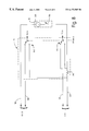
- FIG. 2 is a schematic diagram showing an inductance canceling circuit for use with Kelvin probes in accordance with the invention.
- FIG. 3 is a simplified schematic diagram of a DC coupled AC amplifier of FIG. 1 .
- FIG. 4A is a simplified schematic diagram of one stage of a critically damped filter of FIG. 1 .
- FIG. 4B is a graph of amplitude versus frequency showing the signal response of the filter of FIG. 4 A.
- FIG. 5 is a simplified schematic diagram of an adjustable gain amplifier of FIG. 1 .
- FIG. 6 is a simplified block diagram of a DC to DC convertor in accordance with another aspect of the invention.
- FIG. 7 is a simplified electrical schematic diagram of a shut down circuit in accordance with another aspect of the invention.
- the present invention includes a battery tester in which current is either injected into or drawn from (i.e., a current sink) the battery. The current is alternately engaged and disengaged at a desired AC frequency.
- the invention provides a number of advantages over the use of a large resistive load including:
- High compliance the ability to test batteries from 1 to 6 cells with a single circuit without possibility of damaging the circuit.
- FIG. 1 is a simplified block diagram of a battery test device 10 which is one embodiment of an apparatus for monitoring the condition of a storage battery 12 in accordance with aspects of the present invention.
- Battery test device 10 couples to terminals 14 A and 14 B of battery 12 using a four point Kelvin connection formed with cables 16 A, 16 B, 18 A and 18 B through an inductance cancellation cable 20 and a self calibration circuit 21 .
- a switched current source 22 comprising a switch 22 A and a current source 22 B is provided and is coupled in series with cables 18 A and 18 B.
- switch 22 A operates at between about 5 Hz and about 500 Hz.
- Cables 16 A and 16 B are connected to a high impedance DC coupled AC amplifier 24 in accordance with one aspect of the invention.
- DC coupled AC amplifier provides an amplified output 26 to a critically damped filter 28 in accordance with another aspect of the invention which provides a filtered output 30 to an auto range amplifier 32 in accordance with another aspect.
- An output 34 from auto range amplifier 32 is provided to analog to digital convertor 36 which in turn provides an output 38 to microprocessor 40 .
- Microprocessor is coupled to a display output 42 and a keypad, keyboard or other use input 44 .
- I/O 46 can be coupled to microprocessor 40 .
- microprocessor 40 can couple to an external printer, data communications device such as a modem, or an external storage device.
- I/O 46 may be coupled using physical cabling or through non-physical links such as infrared, ultrasonic or radio frequency.
- Battery test device 10 is powered by DC to DC convertor 48 in accordance with another aspect of the present invention.
- FIG. 2 is a simplified schematic diagram of inductance cancellation cable 20 which couples battery 12 to current source 22 and DC coupled AC amplifier 24 through a Kelvin connection.
- One problem with prior art battery testers has been the mutual inductance due to the Kelvin connections used to couple to the battery. This has lead to the inductive coupling of the current in the sense leads due to their proximity.
- a transformer coupling arrangement as shown in FIG. 2, is provided which effectively “nulls out” the undesirable cross coupling. This allows the present invention to be used with multiple, interchangeable cables, even on large capacity batteries.
- Transformer 50 is connected with coils 52 and 54 in series with Kelvin leads 16 B and 18 B, respectively. Coils 52 and 54 are wound in opposite directions on an iron core 56 .
- the current in leads 18 B and 18 A from current source 22 is inductively coupled into leads 16 B and 16 A.
- transformer 50 causes an opposed cancellation current to be coupled into leads 16 B and 16 A.
- the coupling between 52 and 54 can be controlled by adjusting the position of core 56 .
- Such “tuning” can be performed during manufacture.
- the cables 16 A, 16 B, 18 A and 18 B can be removably coupled to battery testing device 10 such that if the cables are damaged or are otherwise desired to be replaced, a new cable pair can be attached.
- the new cable pair includes its own transformer 50 and has been “tuned” by adjusting core 56 during manufacture such that the noise current is effectively nulled out.
- inductance canceling cable 20 allows the cable to be of relatively long lengths without suffering from excessive inductive coupling between the cables.
- the battery testing circuitry can be a distance away from the battery, such as held by an operator at a test stand or while sitting inside an automobile, while performing a battery test. Long or short cables or other cabling configurations can be easily exchanged by simply disconnecting a cable pair from the test device 10 and reconnecting a desired pair. As the cable has been previously tuned for appropriate cancellation, the operator does not need to perform any further adjustments in the field.
- the transformer shown in FIG. 2 is simply one implementation of this concept and other techniques for introducing a cancellation signal such as through active devices or other coupling techniques is considered within the scope of the present invention.
- FIG. 3 is a simplified diagram of DC coupled AC amplifier 24 in accordance with another aspect of the present invention.
- DC coupled AC amplifier 24 includes differential amplifier 60 and differential amplifier 62 .
- the non-inverting input of amplifier 60 is connected to cable 16 A shown in FIG. 1 through a resistor 64 and the inverting input to amplifier 60 couples to cable 16 B through coil 52 as illustrated in FIG. 2 and further through resistor 66 .
- the output of amplifier 60 is connected to the inverting input of amplifier 60 through resistor 68 to provide negative feedback. Further, the output of amplifier 60 is coupled to the non-inverting input of amplifier 60 through integrator 70 and resistors 72 and 74 .
- Invertor 70 is formed through differential amplifier 62 having negative feedback from its output to its inverting input through capacitor 76 .
- the non-inverting input of differential amplifier 62 is coupled to electrical ground 78 .
- the DC coupled AC amplifier 24 has a unity gain.
- AC coupled amplifiers have been used in battery testers.
- such amplifiers induce common mode errors, as well as variability in impedance due to changes in, for example, capacitors used to couple to the sense signal.
- the coupling capacitors must be relatively large to avoid distortion in the input sense signal. Such capacitors have the negative effect of reducing the settling time necessary to obtain an accurate measurement.
- AC coupling has been used in prior art battery testers to avoid multiplying the DC voltage of the battery by the corresponding high gain of the amplifier. The use of a DC coupled AC amplifier overcomes these problems and does not require large coupling capacitors.
- DC coupled AC amplifier 24 receives a DC error signal 80 representative of the DC signal present on the output of amplifier 60 .
- the DC error signal 80 is generated by integrator 70 which has a time constant determined by capacitor 76 selected for the particular application based upon the frequency of operation of switch 22 A used in switched current source 22 .
- the output 26 of DC coupled AC amplifier 24 is a purely AC signal generated in response to application of the switched current source 22 .
- the implementation illustrated in FIG. 3 is merely one example which shows the preferred embodiment of a DC coupled amplifier in accordance with the present invention.
- the present invention includes any coupling technique for use in sensing an AC signal from a battery under test which does not require a large AC coupling capacitor to block the DC voltage from the battery.
- FIG. 4A is a simplified diagram of one second order filter stage 100 of critically damped filter 28 shown in FIG. 1 .
- FIG. 4B is a graph of amplitude versus frequency illustrating the characteristics of filter 28 in accordance with the invention.
- filter 28 comprises four such stages 100 .
- Stage 100 includes a differential amplifier 110 having negative feedback through a resistor 102 and a capacitor 104 .
- An input signal is received through resistor 106 and capacitor 108 and coupled to the inverting input of amplifier 110 .
- the non-inverting input of amplifier 110 is coupled to electrical ground 78 through resistor 112 .
- Filter 100 forms a second order band-pass filter and is used as a single stage of critically damped filter 28 shown in FIG. 1 .
- Critically damped filter 28 includes a total of four such stages connected in series.
- Critically damped filter 28 provides a critically damped band-pass filter as illustrated in FIG. 4 B.
- FIG. 4B also illustrates an over damped filter and an under damped filter.
- filter 28 has a Q equal to 1 and a band-pass center frequency (fo) configured to be the same as the frequency of switch 22 A shown in FIG. 1 . If the filter is overdamped, the system will be slow to respond. If the system is underdamped, the signal will “ring”. This allows substantially only components in the response signal across battery 12 which are at the same frequency as current source 22 to be passed to autorange amplifier 30 . Note that additional filter stages beyond the preferred eight may be used, however, this will lead to increased manufacturing costs. In one preferred embodiment, amplifier 28 has a total gain of 16 . Any type of filter can be implemented in accordance with this aspect of the present invention. The particular analog filter shown is simply one preferred embodiment. Further, a filter can also be implemented digitally.
- FIG. 5 is a simplified diagram of auto range (programmable gain or selectable gain) amplifier 32 .
- amplifier 32 is a two stage amplifier having a first stage 140 having selectable gains of 1, 2, 4 and 8 and a second stage amplifier 142 having selectable gains of 1, 10, 100 and 1000.
- Amplifier 140 is coupled to output 30 from critically damped filter 28 through coupling capacitor 144 .
- Amplifier 140 includes selectable gain amplifier 146 and resistor 148 .
- Amplifier 146 receives inputs A 0 and A 1 which control the amplification provided by amplifier 146 .
- Amplifier stage 142 includes amplifier 150 having an input coupled to resistor 152 and to the output of amplifier 146 through coupling capacitor 154 .
- the gain of amplifier 150 is controlled by control inputs A 2 and A 3 .
- Amplifiers 146 and 150 are coupled to microprocessor 40 through control inputs A 0 through A 3 .
- Microprocessor 40 controls the gain of amplifier 32 by selectively changing inputs A 0 through A 3 according to the following table:
- amplifier 32 provides a programmable gain of between 1 and 8000. Under the control of microprocessor 40 , the gain of amplifier 32 can be adjusted such that battery test device 10 is capable of testing batteries having a wide range of resistances or conductance (i.e., between 10 mhos and 10,000 mhos).
- Microprocessor 40 increases the gain of amplifier 32 by controlling inputs A 0 through A 3 until a maximum signal through analog to digital convertor 36 is received. This adjustment is performed automatically and does not require intervention from an operator. This improves the ease of use of device 10 and reduces the likelihood of an incorrect measurement due to operator error.
- the adjustable gain amplifier 32 shown in FIG. 5 is simply one preferred embodiment of an adjustable amplifier and the present invention includes any amplifier configuration. Further, the amplifier can be placed anywhere in the signal path and does need to be located between a critically damped filter such as filter 28 and an analog to digital convertor 36 .
- FIG. 6 is a simplified schematic diagram of DC to DC convertor circuitry 48 in accordance with another aspect of the present invention.
- Circuitry 48 includes a switching type DC to DC convertor 170 which includes positive and negative inputs, positive and negative outputs and a synchronization input.
- FIG. 6 also shows voltages V CC , V′ CC , +V SS and ⁇ V SS .
- V CC is typically supplied by either an internal voltage source such as an internal battery or is derived from the battery under test 12 if battery 12 is sufficiently large.
- V CC is coupled to the positive input of convertor 170 and to V′ CC through resistor 172 .
- Capacitor 174 couples V CC to ground 78 and capacitor 176 couples V′ CC to ground 78 .
- V CC is used to drive very low noise circuitry such as amplifier 24 , filter 28 , amplifier 32 , etc.
- V′ CC is used to power circuitry which may create noise and is itself less susceptible to noise such as microprocessor 40 and other digital and logic circuitry.
- the voltages +V SS and ⁇ V SS are used to power some analog components which require multiple supply voltages such as plus and minus 15 volts.
- Inductors 178 and 180 block noise from convertor 170 from supply voltages +V SS and ⁇ V SS .
- convertor 170 is a switching convertor with a frequency of about 400 KHz and the microprocessor 40 operates at about 4 MHz.
- the noise isolation provided in the embodiment of FIG. 6 reduces noise in critical components of battery test device 10 and thereby improves measurement accuracy.
- Convertor 170 also includes a power reduction technique in which the synchronous in (SYNCIN) signal is provided by microprocessor 40 . In some instances, analog test circuitry is not required for operation. During these time periods, microprocessor 40 can control the SYNCIN to convertor 170 such that convertor 170 is turned off and supply voltages +V SS and ⁇ V SS are not generated. This provides reduced power requirements.
- SYNCIN synchronous in
- Another aspect of the present invention includes improved internal (power supply) battery lifetime.
- the invention can be used to test batteries with an open circuit voltage as low as 1.75 volts by using internal battery. (If battery 12 is large enough, device 10 can be powered by battery 12 ). However, rather than requiring an expensive rechargeable battery pack, a simple replaceable battery such as a disposable 9 volt battery can be used. This is possible even though such a battery provides a relatively low capacity source of power because the present invention includes a number of circuits requiring reduced power to thereby improve battery life. These circuits include a bipolar analog power shutdown circuit 200 (FIG. 7 ), a high speed top-down auto-ranging circuit to minimize test time, and an automatic power down circuit for supply 48 (explained above).
- the amplifier 32 auto ranges over a range of 1 to 8000. When engaged, amplifier 32 consumes 10 times the internal battery power in comparison to when the amplifier is not engaged. Therefore, it is advantageous to limit the time the amplifier is on. Conductance decreases with increasing cell count due to series resistance stack-up. As a result, lower conductance measurements require less gain than higher conductance measurements.
- the cell count of battery 12 will be known by microprocessor 40 because it has been input by an operator.
- Microprocessor 40 can then control the initial gain of amplifier 32 required for measurement. From the initial gain, the microprocessor can adjust the gain of amplifier 32 either up or down to obtain the appropriate gain for a particular battery configuration. This greatly reduces the amount of time required to obtain a measurement and therefore reduces power consumption.
- the initial gain of amplifier stage 32 is as follows:
- Shutdown circuit 200 is illustrated in FIG. 7 and can be used to cut off all power to analog circuitry in device 10 .
- Circuit 200 includes internal battery 202 , transistors 204 and 206 , diode 208 and biasing resistors 210 , 212 , 214 and 216 .
- transistor 204 turns on which in turn activates transistor 206 such that a voltage V DD from internal battery 202 is provided at an output of circuit 200 .
- V DD is then used to power analog components in device 10 .
- transistor 206 upon removal of battery 12 , transistor 206 will turn off thereby terminating supply voltage V DD .
- microprocessor 40 can selectively terminate supply voltage V DD by providing a signal through diode 208 to turn transistor 206 off.
- one aspect of the present invention includes disconnecting those components which are not in use from the internal power supply generating from the internal battery 202 of device 10 .
- the various techniques for implementing this aspect of the invention are simply one preferred embodiment. Those skilled in the art will recognize that other techniques may be used to terminate power to various components or otherwise turn various components off.
- Circuitry 21 includes a manganin shunt conductance standard 240 .
- Shunt 240 can be calibrated against a standard traceable to NIST.
- Switches 240 , 242 and 244 are coupled to microprocessor 40 and are adapted to selectively switch shunt 240 in series with amplifier 24 .
- Microprocessors can then measure the conductance of Shunts 240 using amplifier 24 , filter 28 , amplifier 32 and analog to digital convertor 36 and compare the measured reading with the calibrated standard stored in a memory 40 A in microprocessor 40 .
- the difference between the measured value and calibrated value can be used to introduce a correction factor and subsequent measurements to thereby maintain calibration of tester 10 .
- the calibration can occur automatically when tester 10 is initially coupled to battery 12 or can be initiated by a user through keyboard 44 .
- memory 48 of microprocessor 40 contains various predefined reference standards.
- the appropriate reference standard for a particular battery 12 is selected by an operator through input 44 . Further, an operator can recall the standard stored in memory 40 A and view them through display 42 . If a standard has been changed or otherwise it wished to modify to a standard, the operator can change the standards using input 44 .
- the standard stored in memory 40 A can also be printed out, for example, using input/output port 46 .
- a temperature sensor 250 shown in FIG. 1 can provide a temperature input to microprocessor 40 .
- sensor 250 can comprise a thermal couple, thermistor or an infrared temperature sensor directed toward battery 12 .
- An analog to digital convertor (not shown) provides a digital representation of temperature 250 to microprocessor 40 .
- microprocessor 40 can modify the test results based upon information stored in memory 40 A to thereby compensate for temperature variations.
- FIG. 1 can be implemented using any appropriate technique and are not limited to those disclosed herein. Further, the various aspects of the invention can be implemented in any particular order and are not limited to the order shown in FIG. 1 .
- the functional blocks can be implemented in either analog or digital circuitry or their hybrid.
- current source 22 B can be selectively switched in using switch 22 A.
- the invention also includes application of a voltage and measuring the resultant current response.
- the invention can be used with conductance, admittance, impedance or resistance based battery test circuitry. Further, some aspects of the invention may be used with any type of battery tester including load testers, simple voltage testers, testers that require the battery to be placed through a number of conditioning steps, etc.
Landscapes
- Physics & Mathematics (AREA)
- General Physics & Mathematics (AREA)
- Tests Of Electric Status Of Batteries (AREA)
- Secondary Cells (AREA)
- Measurement Of Current Or Voltage (AREA)
- Charge And Discharge Circuits For Batteries Or The Like (AREA)
Abstract
An apparatus for electronically testing or monitoring the condition of a storage battery is provided. The apparatus includes an inductance cancellation circuit for use in a Kelvin probe of an electronic battery tester. The induction cancellation circuit reduces inductive coupling between leads of the Kelvin probe. The apparatus also includes a DC coupled AC amplifier for amplifying an AC response signal of an electronic battery tester. Other aspects include a critically damped band-pass filter a response signal, a DC to DC convertor isolation circuit, operator editable test criteria, a battery temperature sensing element, an automatically adjustable gain stage and the use of an internal reference standard for a self calibration.
Description
The present invention claims priority to Provisional Application Ser. No. 60/083,140, filed Apr. 27, 1998 and entitled BATTERY TESTER.
The present invention relates to testing of storage batteries. More specifically, the present invention relates to electronic battery testers used to test storage batteries.
Storage batteries, such as lead acid storage batteries of the type used in the automotive or power standby industries, have existed for many years. However, understanding the nature of such storage batteries, how such storage batteries operate and how to accurately test such batteries has been an ongoing endeavor and has proved quite difficult. Storage batteries consist of a plurality of individual storage cells electrically connected in series. Typically each cell has a voltage potential of about 2.1 volts. By connecting the cells in series, the voltages of the individual cells are added in a cumulative manner. For example, in a typical automotive storage battery, six storage cells are used to provide a total voltage when the battery is fully charged of 12.6 volts.
There has been a history of attempts to accurately test the condition of storage batteries. A simple test is to measure the voltage of the battery. If the voltage is below a certain threshold, the battery is determined to be bad. However, this test is inconvenient because it requires the battery to be charged prior to performing the test. If the battery is discharged, the voltage will be low and a good battery may be incorrectly tested as bad. Furthermore, such a test does not give any indication of how much energy is stored in the battery. Another technique for testing a battery is referred as a load test. In a load test, the battery is discharged using a known load. As the battery is discharged, the voltage across the battery is monitored and used to determine the condition of the battery. This technique requires that the battery be sufficiently charged in order that it can supply current to the load.
More recently, a technique has been pioneered by Dr. Keith S. Champlin and Midtronics, Inc. of Burr Ridge, Ill. for testing storage batteries by measuring the conductance of the batteries. Aspects of this technique are described in a number of United States patents, for example, U.S. Pat. No. 3,873,911, issued Mar. 25, 1975, to Champlin, entitled ELECTRONIC BATTERY TESTING DEVICE; U.S. Pat. No. 3,909,708, issued Sep. 30, 1975, to Champlin, entitled ELECTRONIC BATTERY TESTING DEVICE; U.S. Pat. No. 4,816,768, issued Mar. 28, 1989, to Champlin, entitled ELECTRONIC BATTERY TESTING DEVICE; U.S. Pat. No. 4,825,170, issued Apr. 25, 1989, to Champlin, entitled ELECTRONIC BATTERY TESTING DEVICE WITH AUTOMATIC VOLTAGE SCALING; U.S. Pat. No. 4,881,038, issued Nov. 14, 1989, to Champlin, entitled ELECTRONIC BATTERY TESTING DEVICE WITH AUTOMATIC VOLTAGE SCALING TO DETERMINE DYNAMIC CONDUCTANCE; U.S. Pat. No. 4,912,416, issued Mar. 27, 1990, to Champlin, entitled ELECTRONIC BATTERY TESTING DEVICE WITH STATE-OF-CHARGE COMPENSATION; U.S. Pat. No. 5,140,269, issued Aug. 18, 1992, to Champlin, entitled ELECTRONIC TESTER FOR ASSESSING BATTERY/CELL CAPACITY; U.S. Pat. No. 5,343,380, issued Aug. 30, 1994, entitled METHOD AND APPARATUS FOR SUPPRESSING TIME VARYING SIGNALS IN BATTERIES UNDERGOING CHARGING OR DISCHARGING; U.S. Pat. No. 5,572,136, issued Nov. 5, 1996, entitled ELECTRONIC BATTERY TESTER WITH AUTOMATIC COMPENSATION FOR LOW STATE-OF-CHARGE; U.S. Pat. No. 5,574,355, issued Nov. 12, 1996, entitled METHOD AND APPARATUS FOR DETECTION AND CONTROL OF THERMAL RUNAWAY IN A BATTERY UNDER CHARGE; U.S. Pat. No. 5,585,728, issued Dec. 17, 1996, entitled ELECTRONIC BATTERY TESTER WITH AUTOMATIC COMPENSATION FOR LOW STATE-OF-CHARGE; U.S. Pat. No. 5,592,093, issued Jan. 7, 1997, entitled ELECTRONIC BATTERY TESTING DEVICE LOOSE TERMINAL CONNECTION DETECTION VIA A COMPARISON CIRCUIT; U.S. Pat. No. 5,598,098, issued Jan. 28, 1997, entitled ELECTRONIC BATTERY TESTER WITH VERY HIGH NOISE IMMUNITY; U.S. Pat. No. 5,757,192, issued May 26, 1998, entitled METHOD AND APPARATUS FOR DETECTING A BAD CELL IN A STORAGE BATTERY; U.S. Pat. No. 5,821,756, issued Oct. 13, 1998, entitled ELECTRONIC BATTERY TESTER WITH TAILORED COMPENSATION FOR LOW STATE-OF-CHARGE; and U.S. Pat. No. 5,831,435, issued Nov. 3, 1998, entitled BATTERY TESTER FOR JIS STANDARD.
The present invention includes apparatuses and methods for electronically testing or monitoring the condition of a storage battery. One aspect of the invention includes an inductance cancellation circuit for use in a Kelvin probe of an electronic battery tester. The induction cancellation circuit reduces inductive coupling between leads of the Kelvin probe. Another aspect of the invention includes a DC coupled AC amplifier for amplifying an AC response signal of an electronic battery tester. Other aspects include a critically damped band-pass filter, a DC to DC convertor isolation circuit, operator editable test criteria, a battery temperature sensing element, an automatically adjustable gain stage and the use of an internal reference standard for a self calibration.
FIG. 1 is a simplified block diagram showing a battery test device in accordance with aspects of the present invention.
FIG. 2 is a schematic diagram showing an inductance canceling circuit for use with Kelvin probes in accordance with the invention.
FIG. 3 is a simplified schematic diagram of a DC coupled AC amplifier of FIG. 1.
FIG. 4A is a simplified schematic diagram of one stage of a critically damped filter of FIG. 1.
FIG. 4B is a graph of amplitude versus frequency showing the signal response of the filter of FIG. 4A.
FIG. 5 is a simplified schematic diagram of an adjustable gain amplifier of FIG. 1.
FIG. 6 is a simplified block diagram of a DC to DC convertor in accordance with another aspect of the invention.
FIG. 7 is a simplified electrical schematic diagram of a shut down circuit in accordance with another aspect of the invention.
FIG. 8 is a simplified electrical schematic diagram showing a calibration circuit in accordance with another aspect of the invention.
There is an ongoing need for improved testing of storage batteries. The present invention includes a battery tester in which current is either injected into or drawn from (i.e., a current sink) the battery. The current is alternately engaged and disengaged at a desired AC frequency. The invention provides a number of advantages over the use of a large resistive load including:
Immunity from contact resistance variations.
High compliance—the ability to test batteries from 1 to 6 cells with a single circuit without possibility of damaging the circuit.
Fixed and/or predictable current coupling effects in the sensing lead wires used to couple to the battery.
Given the function G (conductance)=I/E, a substantially constant current implies substantially constant I. Therefore, only the value of E needs to be measured and a simple inversion results in a quantity directly proportional to G.
Reduced requirements for electrically fusing the device.
FIG. 1 is a simplified block diagram of a battery test device 10 which is one embodiment of an apparatus for monitoring the condition of a storage battery 12 in accordance with aspects of the present invention. Battery test device 10 couples to terminals 14A and 14B of battery 12 using a four point Kelvin connection formed with cables 16A, 16B, 18A and 18B through an inductance cancellation cable 20 and a self calibration circuit 21. A switched current source 22 comprising a switch 22A and a current source 22B is provided and is coupled in series with cables 18A and 18B. In one embodiment, switch 22A operates at between about 5 Hz and about 500 Hz. Cables 16A and 16B are connected to a high impedance DC coupled AC amplifier 24 in accordance with one aspect of the invention. DC coupled AC amplifier provides an amplified output 26 to a critically damped filter 28 in accordance with another aspect of the invention which provides a filtered output 30 to an auto range amplifier 32 in accordance with another aspect. An output 34 from auto range amplifier 32 is provided to analog to digital convertor 36 which in turn provides an output 38 to microprocessor 40. Microprocessor is coupled to a display output 42 and a keypad, keyboard or other use input 44. Optionally, other types of inputs and outputs illustrated as I/O 46, can be coupled to microprocessor 40. For example, microprocessor 40 can couple to an external printer, data communications device such as a modem, or an external storage device. I/O 46 may be coupled using physical cabling or through non-physical links such as infrared, ultrasonic or radio frequency. Battery test device 10 is powered by DC to DC convertor 48 in accordance with another aspect of the present invention.
FIG. 2 is a simplified schematic diagram of inductance cancellation cable 20 which couples battery 12 to current source 22 and DC coupled AC amplifier 24 through a Kelvin connection. One problem with prior art battery testers has been the mutual inductance due to the Kelvin connections used to couple to the battery. This has lead to the inductive coupling of the current in the sense leads due to their proximity. However, with the present invention a transformer coupling arrangement, as shown in FIG. 2, is provided which effectively “nulls out” the undesirable cross coupling. This allows the present invention to be used with multiple, interchangeable cables, even on large capacity batteries. Transformer 50 is connected with coils 52 and 54 in series with Kelvin leads 16B and 18B, respectively. Coils 52 and 54 are wound in opposite directions on an iron core 56.
In operation, the current in leads 18B and 18A from current source 22 is inductively coupled into leads 16B and 16A. In prior art battery testers, this can be a source of measurement errors. However, transformer 50 causes an opposed cancellation current to be coupled into leads 16B and 16A. The coupling between 52 and 54 can be controlled by adjusting the position of core 56. Such “tuning” can be performed during manufacture. Further, the cables 16A, 16B, 18A and 18B can be removably coupled to battery testing device 10 such that if the cables are damaged or are otherwise desired to be replaced, a new cable pair can be attached. The new cable pair includes its own transformer 50 and has been “tuned” by adjusting core 56 during manufacture such that the noise current is effectively nulled out. Note that in less critical applications, a fixed transformer can be used and the transformer coupling does not require tuning. Further, the use of inductance canceling cable 20 allows the cable to be of relatively long lengths without suffering from excessive inductive coupling between the cables. For example, the battery testing circuitry can be a distance away from the battery, such as held by an operator at a test stand or while sitting inside an automobile, while performing a battery test. Long or short cables or other cabling configurations can be easily exchanged by simply disconnecting a cable pair from the test device 10 and reconnecting a desired pair. As the cable has been previously tuned for appropriate cancellation, the operator does not need to perform any further adjustments in the field. The transformer shown in FIG. 2 is simply one implementation of this concept and other techniques for introducing a cancellation signal such as through active devices or other coupling techniques is considered within the scope of the present invention.
FIG. 3 is a simplified diagram of DC coupled AC amplifier 24 in accordance with another aspect of the present invention. DC coupled AC amplifier 24 includes differential amplifier 60 and differential amplifier 62. In the embodiments shown, the non-inverting input of amplifier 60 is connected to cable 16A shown in FIG. 1 through a resistor 64 and the inverting input to amplifier 60 couples to cable 16B through coil 52 as illustrated in FIG. 2 and further through resistor 66. The output of amplifier 60 is connected to the inverting input of amplifier 60 through resistor 68 to provide negative feedback. Further, the output of amplifier 60 is coupled to the non-inverting input of amplifier 60 through integrator 70 and resistors 72 and 74. Invertor 70 is formed through differential amplifier 62 having negative feedback from its output to its inverting input through capacitor 76. The non-inverting input of differential amplifier 62 is coupled to electrical ground 78. In one preferred embodiment, the DC coupled AC amplifier 24 has a unity gain.
In the prior art, AC coupled amplifiers have been used in battery testers. However, such amplifiers induce common mode errors, as well as variability in impedance due to changes in, for example, capacitors used to couple to the sense signal. In addition, the coupling capacitors must be relatively large to avoid distortion in the input sense signal. Such capacitors have the negative effect of reducing the settling time necessary to obtain an accurate measurement. However, AC coupling has been used in prior art battery testers to avoid multiplying the DC voltage of the battery by the corresponding high gain of the amplifier. The use of a DC coupled AC amplifier overcomes these problems and does not require large coupling capacitors.
In the particular embodiment shown, DC coupled AC amplifier 24 receives a DC error signal 80 representative of the DC signal present on the output of amplifier 60. The DC error signal 80 is generated by integrator 70 which has a time constant determined by capacitor 76 selected for the particular application based upon the frequency of operation of switch 22A used in switched current source 22. Thus, the output 26 of DC coupled AC amplifier 24 is a purely AC signal generated in response to application of the switched current source 22. The implementation illustrated in FIG. 3 is merely one example which shows the preferred embodiment of a DC coupled amplifier in accordance with the present invention. However, the present invention includes any coupling technique for use in sensing an AC signal from a battery under test which does not require a large AC coupling capacitor to block the DC voltage from the battery.
FIG. 4A is a simplified diagram of one second order filter stage 100 of critically damped filter 28 shown in FIG. 1. FIG. 4B is a graph of amplitude versus frequency illustrating the characteristics of filter 28 in accordance with the invention. In a preferred embodiment, filter 28 comprises four such stages 100. Stage 100 includes a differential amplifier 110 having negative feedback through a resistor 102 and a capacitor 104. An input signal is received through resistor 106 and capacitor 108 and coupled to the inverting input of amplifier 110. The non-inverting input of amplifier 110 is coupled to electrical ground 78 through resistor 112.
Filter 100 forms a second order band-pass filter and is used as a single stage of critically damped filter 28 shown in FIG. 1. Critically damped filter 28 includes a total of four such stages connected in series.
Critically damped filter 28 provides a critically damped band-pass filter as illustrated in FIG. 4B. FIG. 4B also illustrates an over damped filter and an under damped filter. Preferably, filter 28 has a Q equal to 1 and a band-pass center frequency (fo) configured to be the same as the frequency of switch 22A shown in FIG. 1. If the filter is overdamped, the system will be slow to respond. If the system is underdamped, the signal will “ring”. This allows substantially only components in the response signal across battery 12 which are at the same frequency as current source 22 to be passed to autorange amplifier 30. Note that additional filter stages beyond the preferred eight may be used, however, this will lead to increased manufacturing costs. In one preferred embodiment, amplifier 28 has a total gain of 16. Any type of filter can be implemented in accordance with this aspect of the present invention. The particular analog filter shown is simply one preferred embodiment. Further, a filter can also be implemented digitally.
FIG. 5 is a simplified diagram of auto range (programmable gain or selectable gain) amplifier 32. In the embodiment shown in FIG. 5, amplifier 32 is a two stage amplifier having a first stage 140 having selectable gains of 1, 2, 4 and 8 and a second stage amplifier 142 having selectable gains of 1, 10, 100 and 1000. Amplifier 140 is coupled to output 30 from critically damped filter 28 through coupling capacitor 144. Amplifier 140 includes selectable gain amplifier 146 and resistor 148. Amplifier 146 receives inputs A0 and A1 which control the amplification provided by amplifier 146. Amplifier stage 142 includes amplifier 150 having an input coupled to resistor 152 and to the output of amplifier 146 through coupling capacitor 154. The gain of amplifier 150 is controlled by control inputs A2 and A3. Amplifiers 146 and 150 are coupled to microprocessor 40 through control inputs A0 through A3. Microprocessor 40 controls the gain of amplifier 32 by selectively changing inputs A0 through A3 according to the following table:
| TABLE 1 | |||||||||
| A3 | A2 | A1 | A0 | GAIN | A3 | A2 | A1 | A0 | GAIN |
| 0 | 0 | 0 | 0 | 1 | 1 | 0 | 0 | 0 | 100 |
| 0 | 0 | 0 | 1 | 2 | 1 | 0 | 0 | 1 | 200 |
| 0 | 0 | 1 | 0 | 4 | 1 | 0 | 1 | 0 | 400 |
| 0 | 0 | 1 | 1 | 8 | 1 | 0 | 1 | 1 | 800 |
| 0 | 1 | 0 | 0 | 10 | 1 | 1 | 0 | 0 | 1000 |
| 0 | 1 | 0 | 1 | 20 | 1 | 1 | 0 | 1 | 2000 |
| 0 | 1 | 1 | 0 | 40 | 1 | 1 | 1 | 0 | 4000 |
| 0 | 1 | 1 | 1 | 80 | 1 | 1 | 1 | 1 | 8000 |
In operation, amplifier 32 provides a programmable gain of between 1 and 8000. Under the control of microprocessor 40, the gain of amplifier 32 can be adjusted such that battery test device 10 is capable of testing batteries having a wide range of resistances or conductance (i.e., between 10 mhos and 10,000 mhos). Microprocessor 40 increases the gain of amplifier 32 by controlling inputs A0 through A3 until a maximum signal through analog to digital convertor 36 is received. This adjustment is performed automatically and does not require intervention from an operator. This improves the ease of use of device 10 and reduces the likelihood of an incorrect measurement due to operator error. The adjustable gain amplifier 32 shown in FIG. 5 is simply one preferred embodiment of an adjustable amplifier and the present invention includes any amplifier configuration. Further, the amplifier can be placed anywhere in the signal path and does need to be located between a critically damped filter such as filter 28 and an analog to digital convertor 36.
FIG. 6 is a simplified schematic diagram of DC to DC convertor circuitry 48 in accordance with another aspect of the present invention. Circuitry 48 includes a switching type DC to DC convertor 170 which includes positive and negative inputs, positive and negative outputs and a synchronization input. FIG. 6 also shows voltages VCC, V′CC, +VSS and −VSS. VCC is typically supplied by either an internal voltage source such as an internal battery or is derived from the battery under test 12 if battery 12 is sufficiently large. VCC is coupled to the positive input of convertor 170 and to V′CC through resistor 172. Capacitor 174 couples VCC to ground 78 and capacitor 176 couples V′CC to ground 78. The combination of resistor 172 and capacitor 174 and the combination of resistor 172 and capacitor 176 provide filters to signal noise on VCC and V′CC. In one embodiment of the invention, VCC is used to drive very low noise circuitry such as amplifier 24, filter 28, amplifier 32, etc. However, V′CC is used to power circuitry which may create noise and is itself less susceptible to noise such as microprocessor 40 and other digital and logic circuitry. Further, the voltages +VSS and −VSS are used to power some analog components which require multiple supply voltages such as plus and minus 15 volts. Inductors 178 and 180 block noise from convertor 170 from supply voltages +VSS and −VSS. In one embodiment, convertor 170 is a switching convertor with a frequency of about 400 KHz and the microprocessor 40 operates at about 4 MHz. The noise isolation provided in the embodiment of FIG. 6 reduces noise in critical components of battery test device 10 and thereby improves measurement accuracy.
Another aspect of the present invention includes improved internal (power supply) battery lifetime. The invention can be used to test batteries with an open circuit voltage as low as 1.75 volts by using internal battery. (If battery 12 is large enough, device 10 can be powered by battery 12). However, rather than requiring an expensive rechargeable battery pack, a simple replaceable battery such as a disposable 9 volt battery can be used. This is possible even though such a battery provides a relatively low capacity source of power because the present invention includes a number of circuits requiring reduced power to thereby improve battery life. These circuits include a bipolar analog power shutdown circuit 200 (FIG. 7), a high speed top-down auto-ranging circuit to minimize test time, and an automatic power down circuit for supply 48 (explained above).
In one embodiment, the amplifier 32 auto ranges over a range of 1 to 8000. When engaged, amplifier 32 consumes 10 times the internal battery power in comparison to when the amplifier is not engaged. Therefore, it is advantageous to limit the time the amplifier is on. Conductance decreases with increasing cell count due to series resistance stack-up. As a result, lower conductance measurements require less gain than higher conductance measurements.
Typically, the cell count of battery 12 will be known by microprocessor 40 because it has been input by an operator. Microprocessor 40 can then control the initial gain of amplifier 32 required for measurement. From the initial gain, the microprocessor can adjust the gain of amplifier 32 either up or down to obtain the appropriate gain for a particular battery configuration. This greatly reduces the amount of time required to obtain a measurement and therefore reduces power consumption. In one embodiment, the initial gain of amplifier stage 32 is as follows:
| NUMBER OF CELLS | INITIAL GAIN | ||
| 1 | 8000 | ||
| 2 | 4000 | ||
| 3 | 4000 | ||
| 4 | 2000 | ||
| 5 | 1000 | ||
| 6 | 800 | ||
Another aspect of the present invention is a self calibration feature using calibration circuitry 21 shown in a simplified electrical schematic diagram in FIG. 8. Circuitry 21 includes a manganin shunt conductance standard 240. Shunt 240 can be calibrated against a standard traceable to NIST. Switches 240, 242 and 244 are coupled to microprocessor 40 and are adapted to selectively switch shunt 240 in series with amplifier 24. Microprocessors can then measure the conductance of Shunts 240 using amplifier 24, filter 28, amplifier 32 and analog to digital convertor 36 and compare the measured reading with the calibrated standard stored in a memory 40A in microprocessor 40. The difference between the measured value and calibrated value can be used to introduce a correction factor and subsequent measurements to thereby maintain calibration of tester 10. The calibration can occur automatically when tester 10 is initially coupled to battery 12 or can be initiated by a user through keyboard 44.
In yet another aspect of the invention, memory 48 of microprocessor 40 contains various predefined reference standards. The appropriate reference standard for a particular battery 12 is selected by an operator through input 44. Further, an operator can recall the standard stored in memory 40A and view them through display 42. If a standard has been changed or otherwise it wished to modify to a standard, the operator can change the standards using input 44. The standard stored in memory 40A can also be printed out, for example, using input/output port 46.
Automatic temperature compensation is another feature of the present invention. A temperature sensor 250 shown in FIG. 1 can provide a temperature input to microprocessor 40. For example, sensor 250 can comprise a thermal couple, thermistor or an infrared temperature sensor directed toward battery 12. An analog to digital convertor (not shown) provides a digital representation of temperature 250 to microprocessor 40. Based upon the measured temperature, microprocessor 40 can modify the test results based upon information stored in memory 40A to thereby compensate for temperature variations.
Although the present invention has been described with reference to preferred embodiments, workers skilled in the art will recognize that changes may be made in form and detail without departing from the spirit and scope of the invention. The various functional blocks illustrated in FIG. 1 can be implemented using any appropriate technique and are not limited to those disclosed herein. Further, the various aspects of the invention can be implemented in any particular order and are not limited to the order shown in FIG. 1. The functional blocks can be implemented in either analog or digital circuitry or their hybrid. Furthermore, current source 22B can be selectively switched in using switch 22A. The invention also includes application of a voltage and measuring the resultant current response. The invention can be used with conductance, admittance, impedance or resistance based battery test circuitry. Further, some aspects of the invention may be used with any type of battery tester including load testers, simple voltage testers, testers that require the battery to be placed through a number of conditioning steps, etc.
Claims (42)
1. An apparatus for monitoring the condition of a storage battery, comprising:
battery test circuitry adapted to couple to the storage battery through a first Kelvin connection and second Kelvin connection;
first and second electrical leads coupled to a first terminal of the battery test circuitry and adapted to provide the first Kelvin connection to the battery;
third and fourth electrical leads coupled to a second terminal of the battery test circuitry and adapted to provide the second Kelvin connection to the battery; and
induction cancellation circuitry coupling the first electrical lead to the second electrical lead.
2. The apparatus of claim 1 wherein the induction cancellation circuitry provides an opposition current in the second electrical lead as a function of a current in the first electrical lead.
3. The apparatus of claim 2 wherein the current in the first electrical lead comprises an applied current and the second electrical lead provides a voltage sense connection to the battery test circuitry.
4. The apparatus of claim 3 wherein the first electrical lead carries an electrical signal having a frequency between about 5 Hz and about 500 Hz.
5. The apparatus of claim 1 wherein the induction cancellation comprises a transformer.
6. The apparatus of claim 5 wherein a first coil of the transformer is connected in series with the first electrical lead and a second coil of the transformer is connected in series with the second electrical lead.
7. The apparatus of claim 6 wherein the first and second coils are configured with opposed polarities.
8. The apparatus of claim 1 wherein the cancellation circuitry comprises means for providing an opposition current in the second electrical lead as a function of a current in the first electrical lead.
9. The apparatus of claim 1 wherein a first sense current in the first electrical lead is substantially carried in the third electrical lead as a second sense current and the induction cancellation circuit couples the second sense current to the second electrical lead.
10. The apparatus of claim 1 wherein the first electrical lead extends adjacent the second electrical lead.
11. The apparatus of claim 1 wherein the first, second, third and fourth electrical leads are removably coupled to the battery test circuitry and the inductance cancellation circuitry is carried in a housing which carries the first, second, third and fourth electrical leads whereby the induction cancellation circuitry can be adjusted during manufacture for a particular lead configuration.
12. The apparatus of claim 1 wherein the first, second, third and fourth electrical leads are of sufficient length whereby the battery test circuitry can be placed inside the vehicle and the electrical leads will reach a battery carried in an engine compartment of the vehicle.
13. A method of reducing an inductively coupled current in a Kelvin probe of an electronic battery tester, comprising:
coupling to a sense current carried on a first electrical lead of the Kelvin probe; and
supplying an opposed current in a second electrical lead of the Kelvin probe in response to the sense current, the opposed current flowing in opposition to an inductively coupled current in the second electrical lead.
14. The method of claim 13 wherein the step of coupling comprises directing the sense current through a first coil of a transformer and the step of supplying comprises connecting a second coil of the transformer in series with the second electrical lead.
15. The method of claim 14 including adjusting the response of the opposed current to the sense current to substantially cancel the inductively coupled current.
16. The method of claim 15 wherein the step of adjusting comprises adjusting the coupling between the first and second coils of the transformer.
17. An apparatus for monitoring the condition of a storage battery, comprising:
first and second Kelvin connections configured to couple to terminals of the battery;
an AC test signal source adapted to couple to the terminals of the battery through a first terminal of the first Kelvin connection and a first terminal of the second Kelvin connection and inject an AC test signal therethrough;
test circuitry adapted to provide battery condition information in response to a battery response signal; and
a DC coupled AC amplifier adapted to couple to the terminals of the battery through a second connection of the first Kelvin connection and a second connection of the second Kelvin connection and provide the battery response signal to the test circuitry as a function of an AC response signal arising in response to the AC test signal between the battery terminals, the battery response signal substantially independent of DC battery voltage.
18. The apparatus of claim 17 wherein the DC coupled AC amplifier includes a differential amplifier having a DC error signal feedback path between an output of the amplifier and an input of the amplifier.
19. The apparatus of claim 18 wherein the input comprises a non-inverting input of the amplifier.
20. The apparatus of claim 19 including an inverting amplifier in the feedback path.
21. The apparatus of claim 18 including an integrating circuit in the feedback path.
22. The apparatus of claim 17 including a critically damped band-pass filter coupling an output of the differential amplifier to the test circuitry.
23. The apparatus of claim 22 wherein the band-pass filter is adapted to pass frequencies in a frequency range proximate a frequency of the AC test signal.
24. The apparatus of claim 22 wherein the band-pass filter comprises an 8th order filter.
25. The apparatus of claim 17 including a power supply comprising a DC to DC convertor to provide power to analog circuitry.
26. The apparatus of claim 17 wherein the test circuitry includes a memory containing battery test criteria and the battery test criteria can be edited by an operator.
27. The apparatus of claim 17 including a temperature sensing element and the test circuitry performing compensation as a function of the temperature to detect battery temperature.
28. The apparatus of claim 27 wherein the temperature sensing element is directed toward a post of the battery.
29. The apparatus of claim 17 including an adjustable gain stage adapted to amplify the AC response signal.
30. The apparatus of claim 29 wherein amplification of the adjustable gain stage is controlled as a function of conductance of the storage battery.
31. The apparatus of claim 17 including an automatic shutdown circuit to reduce power consumption of the test circuitry.
32. The apparatus of claim 17 including a reference standard and wherein the test circuitry performs a self calibration by selectively applying the AC test signal to the calibrated standard and monitoring a response signal.
33. The apparatus of claim 25 including filtering circuitry to reduce noise coupling into noise sensitive components of the apparatus of the test circuitry.
34. An apparatus for monitoring the condition of a storage battery, comprising:
an AC test signal source adapted to couple to terminals of the battery and inject an AC test signal therethrough;
test circuitry adapted to provide battery condition information in response to a battery response signal; and
a critically damped band-pass filter adapted to couple to the terminals of the battery and provide the battery response signal to the test circuitry as a function of an AC response signal arising in response to the AC test signal between the battery terminals, the battery response signal substantially independent of DC battery voltage.
35. The apparatus of claim 34 wherein the critically damped band-pass filter is adapted to pass frequencies in a frequency range proximate a frequency of the AC test signal.
36. The apparatus of claim 34 wherein the critically damped band-pass filter comprises an 8th order filter.
37. The apparatus of claim 34 including a temperature sensing element and the test circuitry performing compensation as a function of the temperature to detect battery temperature.
38. The apparatus of claim 37 wherein the temperature sensing element is directed toward a post of the battery.
39. An apparatus for monitoring the condition of a storage battery, comprising:
first and second Kelvin connections configured to couple to terminals of the battery;
an AC test signal source adapted to couple to the terminals of the battery through a first terminal of the first Kelvin connection and a first terminal of the second Kelvin connection and inject an AC test signal therethrough;
test circuitry adapted to provide battery condition information in response to a battery response signal; and
an adjustable gain stage adapted to couple to the terminals of the battery through a second connection of the first Kelvin connection and a second connection of the second Kelvin connection and provide the battery response signal to the test circuitry as a function of an AC response signal arising in response to the AC test signal between the battery terminals, the adjustable gain stage having a gain input and wherein the amplification gain of the adjustable gain stage is a function of the gain input.
40. The apparatus of claim 39 wherein amplification gain of the adjustable gain stage is controlled as a function of conductance of the storage battery.
41. The apparatus of claim 40 including a microprocessor to automatically control the gain of the adjustable gain stage.
42. The apparatus of claim 39 including an automatic shutdown circuit to reduce power consumption of the test circuitry.
Priority Applications (8)
| Application Number | Priority Date | Filing Date | Title |
|---|---|---|---|
| US09/264,743 US6172505B1 (en) | 1998-04-27 | 1999-03-09 | Electronic battery tester |
| CNB991059476A CN1142445C (en) | 1998-04-27 | 1999-03-18 | Battery tester |
| JP2000546231A JP2003502792A (en) | 1998-04-27 | 1999-04-12 | Electronic battery tester |
| PCT/US1999/007895 WO1999056121A1 (en) | 1998-04-27 | 1999-04-12 | Electronic battery tester |
| DE69933553T DE69933553T2 (en) | 1998-04-27 | 1999-04-12 | ELECTRONIC BATTERY TESTER |
| EP99917402A EP1075655B1 (en) | 1998-04-27 | 1999-04-12 | Electronic battery tester |
| AU35534/99A AU3553499A (en) | 1998-04-27 | 1999-04-12 | Electronic battery tester |
| HK00103141.2A HK1024058B (en) | 1998-04-27 | 2000-05-26 | Electronic battery tester |
Applications Claiming Priority (2)
| Application Number | Priority Date | Filing Date | Title |
|---|---|---|---|
| US8314098P | 1998-04-27 | 1998-04-27 | |
| US09/264,743 US6172505B1 (en) | 1998-04-27 | 1999-03-09 | Electronic battery tester |
Publications (1)
| Publication Number | Publication Date |
|---|---|
| US6172505B1 true US6172505B1 (en) | 2001-01-09 |
Family
ID=26768985
Family Applications (1)
| Application Number | Title | Priority Date | Filing Date |
|---|---|---|---|
| US09/264,743 Expired - Lifetime US6172505B1 (en) | 1998-04-27 | 1999-03-09 | Electronic battery tester |
Country Status (7)
| Country | Link |
|---|---|
| US (1) | US6172505B1 (en) |
| EP (1) | EP1075655B1 (en) |
| JP (1) | JP2003502792A (en) |
| CN (1) | CN1142445C (en) |
| AU (1) | AU3553499A (en) |
| DE (1) | DE69933553T2 (en) |
| WO (1) | WO1999056121A1 (en) |
Cited By (170)
| Publication number | Priority date | Publication date | Assignee | Title |
|---|---|---|---|---|
| US6225808B1 (en) | 2000-02-25 | 2001-05-01 | Midtronics, Inc. | Test counter for electronic battery tester |
| US6294896B1 (en) | 1998-09-11 | 2001-09-25 | Keith S. Champlin | Method and apparatus for measuring complex self-immitance of a general electrical element |
| US6294897B1 (en) | 1999-09-01 | 2001-09-25 | Keith S. Champlin | Method and apparatus for electronically evaluating the internal temperature of an electrochemical cell or battery |
| US6304087B1 (en) | 2000-09-05 | 2001-10-16 | Midtronics, Inc. | Apparatus for calibrating electronic battery tester |
| US6313607B1 (en) | 1999-09-01 | 2001-11-06 | Keith S. Champlin | Method and apparatus for evaluating stored charge in an electrochemical cell or battery |
| US6313608B1 (en) | 1997-11-03 | 2001-11-06 | Midtronics, Inc. | Method and apparatus for charging a battery |
| US6316914B1 (en) | 1999-05-05 | 2001-11-13 | Midtronics, Inc. | Testing parallel strings of storage batteries |
| US6323650B1 (en) | 1999-04-08 | 2001-11-27 | Midtronics, Inc. | Electronic battery tester |
| US6329793B1 (en) | 1996-07-29 | 2001-12-11 | Midtronics, Inc. | Method and apparatus for charging a battery |
| US6332113B1 (en) | 1996-10-07 | 2001-12-18 | Midtronics, Inc. | Electronic battery tester |
| US6331762B1 (en) | 1997-11-03 | 2001-12-18 | Midtronics, Inc. | Energy management system for automotive vehicle |
| US6351102B1 (en) | 1999-04-16 | 2002-02-26 | Midtronics, Inc. | Automotive battery charging system tester |
| US6359441B1 (en) | 1999-04-30 | 2002-03-19 | Midtronics, Inc. | Electronic battery tester |
| US6363303B1 (en) | 1999-11-01 | 2002-03-26 | Midtronics, Inc. | Alternator diagnostic system |
| US6392414B2 (en) | 1997-01-13 | 2002-05-21 | Midtronics, Inc. | Electronic battery tester |
| US6417669B1 (en) | 2001-06-11 | 2002-07-09 | Keith S. Champlin | Suppressing interference in AC measurements of cells, batteries and other electrical elements |
| US6424158B2 (en) | 1998-07-27 | 2002-07-23 | Midtronics, Inc. | Apparatus and method for carrying out diagnostic tests on batteries and for rapidly charging batteries |
| US6441585B1 (en) | 1999-06-16 | 2002-08-27 | Midtronics, Inc. | Apparatus and method for testing rechargeable energy storage batteries |
| US6445158B1 (en) | 1996-07-29 | 2002-09-03 | Midtronics, Inc. | Vehicle electrical system tester with encoded output |
| US6456045B1 (en) | 1999-04-16 | 2002-09-24 | Midtronics, Inc. | Integrated conductance and load test based electronic battery tester |
| US6466025B1 (en) | 2000-01-13 | 2002-10-15 | Midtronics, Inc. | Alternator tester |
| US6466026B1 (en) | 2001-10-12 | 2002-10-15 | Keith S. Champlin | Programmable current exciter for measuring AC immittance of cells and batteries |
| US6469511B1 (en) | 2001-07-18 | 2002-10-22 | Midtronics, Inc. | Battery clamp with embedded environment sensor |
| US20020171428A1 (en) * | 1997-11-03 | 2002-11-21 | Bertness Kevin I. | Electronic battery tester with network communication |
| US20020180445A1 (en) * | 2000-09-14 | 2002-12-05 | Bertness Kevin I. | Method and apparatus for testing cells and batteries embedded in series/parallel systems |
| US20020193955A1 (en) * | 1999-04-08 | 2002-12-19 | Bertness Kevin I. | Battery test module |
| US20030001579A1 (en) * | 1996-07-29 | 2003-01-02 | Bertness Kevin I. | Method and apparatus for auditing a battery test |
| US20030038637A1 (en) * | 1997-11-03 | 2003-02-27 | Bertness Kevin I. | Automotive vehicle electrical system diagnostic device |
| US20030062875A1 (en) * | 1998-08-10 | 2003-04-03 | Kenji Nakamura | Method and device for judging the condition of secondary batteries and method for regenerating secondary batteries |
| US6544078B2 (en) | 2001-07-18 | 2003-04-08 | Midtronics, Inc. | Battery clamp with integrated current sensor |
| US20030088375A1 (en) * | 2001-10-17 | 2003-05-08 | Bertness Kevin I. | Electronic battery tester with relative test output |
| US6566883B1 (en) | 1999-11-01 | 2003-05-20 | Midtronics, Inc. | Electronic battery tester |
| US6570385B1 (en) | 2001-03-19 | 2003-05-27 | Actron Manufacturing Co. | Handheld tester for starting/charging systems |
| US6586941B2 (en) | 2000-03-27 | 2003-07-01 | Midtronics, Inc. | Battery tester with databus |
| US20030124417A1 (en) * | 1999-04-08 | 2003-07-03 | Bertness Kevin I. | Battery test module |
| US20030128036A1 (en) * | 2002-01-04 | 2003-07-10 | Henningson Dale B. | Microprocessor-based hand-held electrical-testing system and method |
| US20030173971A1 (en) * | 2002-03-14 | 2003-09-18 | Bertness Kevin I. | Electronic battery tester with battery failure temperature determination |
| US20030184258A1 (en) * | 2001-06-22 | 2003-10-02 | Vonderhaar J. David | Booster pack with storage capacitor |
| US6633165B2 (en) | 1997-11-03 | 2003-10-14 | Midtronics, Inc. | In-vehicle battery monitor |
| US6650120B2 (en) | 2001-11-07 | 2003-11-18 | Spx Corporation | Apparatus and method for accessing data stored within a power source |
| US6677759B2 (en) | 2001-05-02 | 2004-01-13 | Microchip Technology Incorporated | Method and apparatus for high-voltage battery array monitoring sensors network |
| US6696819B2 (en) | 2002-01-08 | 2004-02-24 | Midtronics, Inc. | Battery charge control device |
| US20040036443A1 (en) * | 2000-03-27 | 2004-02-26 | Bertness Kevin I. | Modular battery tester for scan tool |
| US20040046566A1 (en) * | 2002-09-05 | 2004-03-11 | Klang James K. | Electronic battery tester configured to predict a load test result |
| US20040054503A1 (en) * | 2002-09-18 | 2004-03-18 | Hamid Namaky | Combined off-board device and starter/charging/battery system tester |
| US6737831B2 (en) | 1999-09-01 | 2004-05-18 | Keith S. Champlin | Method and apparatus using a circuit model to evaluate cell/battery parameters |
| US20040100266A1 (en) * | 2002-11-25 | 2004-05-27 | Liebermann Leonard N. | Electronic battery condition tester |
| US20040104728A1 (en) * | 1996-07-29 | 2004-06-03 | Bertness Kevin I. | Alternator tester with encoded output |
| US6759849B2 (en) | 2000-03-27 | 2004-07-06 | Kevin I. Bertness | Battery tester configured to receive a removable digital module |
| US20040140904A1 (en) * | 2003-01-22 | 2004-07-22 | Bertness Kevin I. | Apparatus and method for protecting a battery from overdischarge |
| US20040145371A1 (en) * | 2001-10-17 | 2004-07-29 | Bertness Kevin I | Query based electronic battery tester |
| US20040157113A1 (en) * | 2002-12-31 | 2004-08-12 | Midtronics, Inc. | Apparatus and method for predicting the remaining discharge time of a battery |
| US6781382B2 (en) | 2002-12-05 | 2004-08-24 | Midtronics, Inc. | Electronic battery tester |
| US6788025B2 (en) | 2001-06-22 | 2004-09-07 | Midtronics, Inc. | Battery charger with booster pack |
| US6795782B2 (en) | 1999-04-08 | 2004-09-21 | Midtronics, Inc. | Battery test module |
| US20040189309A1 (en) * | 2003-03-25 | 2004-09-30 | Bertness Kevin I. | Electronic battery tester cable |
| US20040232918A1 (en) * | 1996-07-29 | 2004-11-25 | Bertness Kevin I. | Automotive battery charging system tester |
| US20040251908A1 (en) * | 2003-06-16 | 2004-12-16 | Midtronics, Inc. | Electronic battery tester having a user interface to configure a printer |
| US20040251876A1 (en) * | 2001-06-22 | 2004-12-16 | Midtronics, Inc. | Apparatus and method for counteracting self discharge in a storage battery |
| US20040257084A1 (en) * | 2003-06-23 | 2004-12-23 | Restaino Harvey A. | Cable for electronic battery tester |
| US20050012510A1 (en) * | 2003-07-15 | 2005-01-20 | Thibedeau Dennis G. | Testing and display of electrical system impedance |
| US20050021475A1 (en) * | 1996-07-29 | 2005-01-27 | Bertness Kevin I. | Electronic battery tester with relative test output |
| US6850037B2 (en) | 1997-11-03 | 2005-02-01 | Midtronics, Inc. | In-vehicle battery monitor |
| US20050024061A1 (en) * | 1997-11-03 | 2005-02-03 | Michael Cox | Energy management system for automotive vehicle |
| US20050052187A1 (en) * | 2003-09-05 | 2005-03-10 | Bertness Kevin I. | Method and apparatus for measuring a parameter of a vehicle electrical system |
| US20050057865A1 (en) * | 2003-07-25 | 2005-03-17 | Midtronics, Inc. | Shunt connection to a PCB of an energy management system employed in an automotive vehicle |
| US20050073314A1 (en) * | 2003-10-03 | 2005-04-07 | Midtronics, Inc. | Electronic battery tester/charger with integrated battery cell temperature measurement device |
| US20050077904A1 (en) * | 2003-10-08 | 2005-04-14 | Midtronics, Inc. | Electronic battery tester with probe light |
| US20050099185A1 (en) * | 2003-11-11 | 2005-05-12 | Klang James K. | Apparatus and method for simulating a battery tester with a fixed resistance load |
| US6906522B2 (en) | 2002-03-29 | 2005-06-14 | Midtronics, Inc. | Battery tester with battery replacement output |
| US20050162124A1 (en) * | 2001-06-22 | 2005-07-28 | Midtronics, Inc. | Battery charger with booster pack |
| US20050162172A1 (en) * | 1997-11-03 | 2005-07-28 | Midtronics, Inc. | Wireless battery monitor |
| US20050184732A1 (en) * | 2004-02-20 | 2005-08-25 | Midtronics, Inc. | Replaceable clamp for electronic battery tester |
| US20050206346A1 (en) * | 2004-03-18 | 2005-09-22 | Midtronics, Inc. | Battery charger with automatic customer notification system |
| US20050212521A1 (en) * | 2000-03-27 | 2005-09-29 | Midtronics, Inc. | Electronic battery tester or charger with databus connection |
| US20050218902A1 (en) * | 1999-04-08 | 2005-10-06 | Midtronics, Inc. | Battery test module |
| US20050225446A1 (en) * | 2004-04-13 | 2005-10-13 | Bertness Kevin I | Theft prevention device for automotive vehicle service centers |
| US20050231205A1 (en) * | 2000-03-27 | 2005-10-20 | Bertness Kevin I | Scan tool for electronic battery tester |
| US20060006876A1 (en) * | 2004-07-12 | 2006-01-12 | Midtronics, Inc. | Wireless battery tester/charger |
| US20060017447A1 (en) * | 2004-07-22 | 2006-01-26 | Bertness Kevin I | Broad-band low-inductance cables for making kelvin connections to electrochemical cells and batteries |
| US20060038572A1 (en) * | 2004-08-20 | 2006-02-23 | Midtronics, Inc. | System for automatically gathering battery information for use during battery testing/charging |
| US7012433B2 (en) | 2002-09-18 | 2006-03-14 | Midtronics, Inc. | Battery tester upgrade using software key |
| US20060125483A1 (en) * | 2004-12-09 | 2006-06-15 | Midtronics, Inc. | Battery tester that calculates its own reference values |
| US7081755B2 (en) | 2002-09-05 | 2006-07-25 | Midtronics, Inc. | Battery tester capable of predicting a discharge voltage/discharge current of a battery |
| US20060164038A1 (en) * | 2005-01-25 | 2006-07-27 | Remi Demers | Power supply charging method and device |
| US20060170397A1 (en) * | 2005-01-28 | 2006-08-03 | Rengaswamy Srinivasan | Battery healty monitor |
| US20060192564A1 (en) * | 2005-02-16 | 2006-08-31 | Brown Dennis V | Centrally monitored sales of storage batteries |
| US20060217914A1 (en) * | 2000-03-27 | 2006-09-28 | Bertness Kevin I | Battery testers with secondary functionality |
| US20060267575A1 (en) * | 2004-04-13 | 2006-11-30 | Midtronics, Inc. | Theft prevention device for automotive vehicle service centers |
| US20060273783A1 (en) * | 2005-06-06 | 2006-12-07 | Keuss Steven D | Dual load tester |
| US7148708B1 (en) * | 2006-03-22 | 2006-12-12 | Btech, Inc. | Probe assembly for minimizing excitation pick-up voltages |
| US20060279288A1 (en) * | 2003-11-11 | 2006-12-14 | Midtronics, Inc. | Apparatus and method for simulating a battery tester with a fixed resistance load |
| US7198510B2 (en) | 2001-11-14 | 2007-04-03 | Midtronics, Inc. | Kelvin connector for a battery post |
| US7246015B2 (en) | 1996-07-29 | 2007-07-17 | Midtronics, Inc. | Alternator tester |
| US20070244660A1 (en) * | 1996-07-29 | 2007-10-18 | Bertness Kevin I | Alternator tester |
| DE112006002329T5 (en) | 2005-08-29 | 2008-07-10 | Midtronics, Inc., Willowbrook | Diagnostic device for electrical installations of motor vehicles |
| US20080204030A1 (en) * | 2007-02-27 | 2008-08-28 | Midtronics, Inc. | Battery tester with promotion feature |
| US7446536B2 (en) | 2000-03-27 | 2008-11-04 | Midtronics, Inc. | Scan tool for electronic battery tester |
| US20090024266A1 (en) * | 2007-07-17 | 2009-01-22 | Bertness Kevin I | Battery tester for electric vehicle |
| US20090051365A1 (en) * | 2003-09-05 | 2009-02-26 | Bertness Kevin I | Method and apparatus for measuring a parameter of a vehicle electrical system |
| US7545146B2 (en) | 2004-12-09 | 2009-06-09 | Midtronics, Inc. | Apparatus and method for predicting battery capacity and fitness for service from a battery dynamic parameter and a recovery voltage differential |
| US20090187495A1 (en) * | 2004-08-20 | 2009-07-23 | Midtronics, Inc. | Simplification of inventory management |
| US20090184165A1 (en) * | 2004-08-20 | 2009-07-23 | Midtronics, Inc. | Integrated tag reader and environment sensor |
| US20090212781A1 (en) * | 2004-08-20 | 2009-08-27 | Midtronics, Inc. | System for automatically gathering battery information |
| US20090295395A1 (en) * | 2007-12-06 | 2009-12-03 | Bertness Kevin I | Storage battery and battery tester |
| US20090311919A1 (en) * | 2008-06-16 | 2009-12-17 | Midtronics, Inc. | Clamp for Electrically Coupling to a Battery Contact |
| US7642786B2 (en) | 2004-06-01 | 2010-01-05 | Midtronics, Inc. | Battery tester capable of identifying faulty battery post adapters |
| US7705602B2 (en) | 1997-11-03 | 2010-04-27 | Midtronics, Inc. | Automotive vehicle electrical system diagnostic device |
| US7808375B2 (en) | 2007-04-16 | 2010-10-05 | Midtronics, Inc. | Battery run down indicator |
| US20110015815A1 (en) * | 2007-07-17 | 2011-01-20 | Bertness Kevin I | Battery tester for electric vehicle |
| US7977914B2 (en) | 2003-10-08 | 2011-07-12 | Midtronics, Inc. | Battery maintenance tool with probe light |
| US20110208451A1 (en) * | 2010-02-25 | 2011-08-25 | Champlin Keith S | Method and apparatus for detecting cell deterioration in an electrochemical cell or battery |
| US20110279122A1 (en) * | 2009-01-28 | 2011-11-17 | Robert Bosch Gmbh | Method, electric circuit arrangement and electric memory unit for determining a characteristic status parameter of the memory unit |
| WO2011159455A1 (en) | 2010-06-18 | 2011-12-22 | Midtronics, Inc. | Battery maintenance device with thermal buffer |
| US8513949B2 (en) | 2000-03-27 | 2013-08-20 | Midtronics, Inc. | Electronic battery tester or charger with databus connection |
| US8710847B2 (en) | 2010-10-28 | 2014-04-29 | Donald Marvin | Self-correcting amplifier system |
| US8738309B2 (en) | 2010-09-30 | 2014-05-27 | Midtronics, Inc. | Battery pack maintenance for electric vehicles |
| US8738310B2 (en) | 2010-12-08 | 2014-05-27 | Paul Swanton | Automatic determination of baselines for battery testing |
| US8872517B2 (en) | 1996-07-29 | 2014-10-28 | Midtronics, Inc. | Electronic battery tester with battery age input |
| US8958998B2 (en) | 1997-11-03 | 2015-02-17 | Midtronics, Inc. | Electronic battery tester with network communication |
| US9018958B2 (en) | 2003-09-05 | 2015-04-28 | Midtronics, Inc. | Method and apparatus for measuring a parameter of a vehicle electrical system |
| US9030173B2 (en) | 2006-07-18 | 2015-05-12 | Global Energy Innovations, Inc. | Identifying and amerliorating a deteriorating condition for battery networks in-situ |
| WO2015089249A1 (en) | 2013-12-12 | 2015-06-18 | Midtronics, Inc. | Battery tester and battery registration tool |
| EP2897229A1 (en) | 2014-01-16 | 2015-07-22 | Midtronics, Inc. | Battery clamp with endoskeleton design |
| US9201120B2 (en) | 2010-08-12 | 2015-12-01 | Midtronics, Inc. | Electronic battery tester for testing storage battery |
| US9229062B2 (en) | 2010-05-27 | 2016-01-05 | Midtronics, Inc. | Electronic storage battery diagnostic system |
| US9244100B2 (en) | 2013-03-15 | 2016-01-26 | Midtronics, Inc. | Current clamp with jaw closure detection |
| US9255955B2 (en) | 2003-09-05 | 2016-02-09 | Midtronics, Inc. | Method and apparatus for measuring a parameter of a vehicle electrical system |
| US9312575B2 (en) | 2013-05-16 | 2016-04-12 | Midtronics, Inc. | Battery testing system and method |
| WO2016123075A1 (en) | 2015-01-26 | 2016-08-04 | Midtronics, Inc. | Alternator tester |
| US9425487B2 (en) | 2010-03-03 | 2016-08-23 | Midtronics, Inc. | Monitor for front terminal batteries |
| WO2016176405A1 (en) | 2015-04-29 | 2016-11-03 | Midtronics, Inc. | Calibration and programming of in-vehicle battery sensors |
| US9496720B2 (en) | 2004-08-20 | 2016-11-15 | Midtronics, Inc. | System for automatically gathering battery information |
| US9537332B2 (en) | 2013-05-30 | 2017-01-03 | Canara, Inc. | Apparatus, system and method for charge balancing of individual batteries in a string of batteries using battery voltage and temperature, and detecting and preventing thermal runaway |
| WO2017151500A1 (en) * | 2016-02-29 | 2017-09-08 | Exa Corporation | Processing data to characterize the thermal behavior of a battery |
| US9851411B2 (en) | 2012-06-28 | 2017-12-26 | Keith S. Champlin | Suppressing HF cable oscillations during dynamic measurements of cells and batteries |
| DE102016218160A1 (en) | 2016-09-21 | 2018-03-22 | Fraunhofer-Gesellschaft zur Förderung der angewandten Forschung e.V. | Apparatus and method for supplying energy to a plurality of energy storage devices and / or for providing energy stored in the energy storage devices |
| US9966676B2 (en) | 2015-09-28 | 2018-05-08 | Midtronics, Inc. | Kelvin connector adapter for storage battery |
| US10046649B2 (en) | 2012-06-28 | 2018-08-14 | Midtronics, Inc. | Hybrid and electric vehicle battery pack maintenance device |
| US10120034B2 (en) | 2015-10-07 | 2018-11-06 | Canara, Inc. | Battery string monitoring system |
| US10222397B2 (en) | 2014-09-26 | 2019-03-05 | Midtronics, Inc. | Cable connector for electronic battery tester |
| WO2019147549A1 (en) | 2018-01-23 | 2019-08-01 | Midtronics, Inc. | Hybrid and electric vehicle battery maintenance device |
| WO2019147546A1 (en) | 2018-01-23 | 2019-08-01 | Midtronics, Inc. | High capacity battery balancer |
| US10429449B2 (en) | 2011-11-10 | 2019-10-01 | Midtronics, Inc. | Battery pack tester |
| US10473555B2 (en) | 2014-07-14 | 2019-11-12 | Midtronics, Inc. | Automotive maintenance system |
| US10608353B2 (en) | 2016-06-28 | 2020-03-31 | Midtronics, Inc. | Battery clamp |
| US10843574B2 (en) | 2013-12-12 | 2020-11-24 | Midtronics, Inc. | Calibration and programming of in-vehicle battery sensors |
| WO2021092109A1 (en) | 2019-11-05 | 2021-05-14 | Midtronics, Inc. | System for charging a series of connected batteries |
| US11054480B2 (en) | 2016-10-25 | 2021-07-06 | Midtronics, Inc. | Electrical load for electronic battery tester and electronic battery tester including such electrical load |
| US11325479B2 (en) | 2012-06-28 | 2022-05-10 | Midtronics, Inc. | Hybrid and electric vehicle battery maintenance device |
| US11474153B2 (en) | 2019-11-12 | 2022-10-18 | Midtronics, Inc. | Battery pack maintenance system |
| US11486930B2 (en) | 2020-01-23 | 2022-11-01 | Midtronics, Inc. | Electronic battery tester with battery clamp storage holsters |
| US11513160B2 (en) | 2018-11-29 | 2022-11-29 | Midtronics, Inc. | Vehicle battery maintenance device |
| US11566972B2 (en) | 2019-07-31 | 2023-01-31 | Midtronics, Inc. | Tire tread gauge using visual indicator |
| US11650259B2 (en) | 2010-06-03 | 2023-05-16 | Midtronics, Inc. | Battery pack maintenance for electric vehicle |
| US11668779B2 (en) | 2019-11-11 | 2023-06-06 | Midtronics, Inc. | Hybrid and electric vehicle battery pack maintenance device |
| US11740294B2 (en) | 2010-06-03 | 2023-08-29 | Midtronics, Inc. | High use battery pack maintenance |
| US11906393B2 (en) * | 2019-01-29 | 2024-02-20 | Ateq | Tracer gas leak detection system and corresponding use |
| US11973202B2 (en) | 2019-12-31 | 2024-04-30 | Midtronics, Inc. | Intelligent module interface for battery maintenance device |
| WO2024258934A1 (en) | 2023-06-13 | 2024-12-19 | Midtronics, Inc. | Electric vehicle maintenance device for low voltage electrical system |
| US12237482B2 (en) | 2019-12-31 | 2025-02-25 | Midtronics, Inc. | Intelligent module interface for battery maintenance device |
| WO2025085631A1 (en) | 2023-10-18 | 2025-04-24 | Midtronics, Inc. | Electric vehicle maintenance device abstract of the disclosure |
| WO2025096499A1 (en) | 2023-10-30 | 2025-05-08 | Midtronics, Inc. | Vehicle maintenance system with dynamic network |
| US12320857B2 (en) | 2016-10-25 | 2025-06-03 | Midtronics, Inc. | Electrical load for electronic battery tester and electronic battery tester including such electrical load |
| US12330513B2 (en) | 2022-02-14 | 2025-06-17 | Midtronics, Inc. | Battery maintenance device with high voltage connector |
| US12392833B2 (en) | 2022-05-09 | 2025-08-19 | Midtronics, Inc. | Electronic battery tester |
| WO2025264894A1 (en) | 2024-06-20 | 2025-12-26 | Midtronics, Inc. | Electric vehicle immobilizing device |
| US12517178B2 (en) | 2021-05-27 | 2026-01-06 | Midtronics, Inc. | Battery monitoring system |
| US12555965B2 (en) | 2021-08-24 | 2026-02-17 | Midtronics, Inc. | Power adapter for automotive vehicle maintenance device |
| US12571851B2 (en) | 2020-03-25 | 2026-03-10 | Cadex Electronics Inc. | Apparatus and methods for testing electrochemical systems |
Families Citing this family (15)
| Publication number | Priority date | Publication date | Assignee | Title |
|---|---|---|---|---|
| AU2001234969A1 (en) * | 2000-02-11 | 2001-08-20 | Midtronics, Inc. | Storage battery with integral battery tester |
| US6359442B1 (en) | 2000-06-08 | 2002-03-19 | Auto Meter Products, Inc. | Microprocessor-based hand-held battery tester system |
| US7256575B2 (en) * | 2004-06-01 | 2007-08-14 | Tektronix, Inc. | Wide bandwidth attenuator input circuit for a measurement probe |
| US8446127B2 (en) | 2005-08-03 | 2013-05-21 | California Institute Of Technology | Methods for thermodynamic evaluation of battery state of health |
| US7595611B2 (en) * | 2005-08-03 | 2009-09-29 | California Institute Of Technology | Electrochemical thermodynamic measurement system |
| CN101303396B (en) * | 2007-05-09 | 2011-07-06 | 比亚迪股份有限公司 | Fuel Cell Performance Monitoring System |
| US9065292B2 (en) | 2010-08-23 | 2015-06-23 | California Institute Of Technology | Methods and systems for charging electrochemical cells |
| CN102486466A (en) * | 2010-12-03 | 2012-06-06 | 中国振华电子集团百智科技有限公司 | Method and apparatus used for detecting cell phone battery heat resistance safety property |
| CN104471415B (en) | 2012-04-27 | 2017-09-01 | 加州理工学院 | embedded chip for battery applications |
| US10556510B2 (en) | 2012-04-27 | 2020-02-11 | California Institute Of Technology | Accurate assessment of the state of charge of electrochemical cells |
| CN103675359B (en) * | 2012-09-11 | 2018-06-08 | 福禄克精密测量有限公司 | Wireless controller for cell tester and the cell tester component comprising the handle |
| JP6168813B2 (en) * | 2013-03-29 | 2017-07-26 | 株式会社ケーヒン | Voltage detector |
| CN105548897A (en) * | 2015-12-25 | 2016-05-04 | 苏州大源自动化科技股份有限公司 | Cell detection system and cell detection method |
| CN110118938B (en) * | 2019-04-11 | 2020-06-02 | 华中科技大学 | Method and device for analyzing internal state of lithium battery based on ultrasonic spectrum |
| DE102022202721A1 (en) | 2022-03-21 | 2023-09-21 | Robert Bosch Gesellschaft mit beschränkter Haftung | Method for balancing multiple current sensors, battery system |
Citations (135)
| Publication number | Priority date | Publication date | Assignee | Title |
|---|---|---|---|---|
| US2514745A (en) | 1946-12-19 | 1950-07-11 | Heyer Ind Inc | Changeable scale electrical testing instrument |
| US3356936A (en) | 1964-02-12 | 1967-12-05 | Litton Prec Products Inc | Method and means for total battery voltage testing |
| US3593099A (en) | 1969-07-24 | 1971-07-13 | Hans K Scholl | Automatic battery tester with recording means for battery performance |
| US3607673A (en) | 1968-03-18 | 1971-09-21 | Magna Corp | Method for measuring corrosion rate |
| US3676770A (en) | 1970-05-15 | 1972-07-11 | Anderson Power Products | Pulse sampling battery fuel gauging and resistance metering method and means |
| US3729989A (en) | 1970-12-10 | 1973-05-01 | D Little | Horsepower and torque measuring instrument |
| US3753094A (en) | 1969-07-01 | 1973-08-14 | Matsushita Electric Industrial Co Ltd | Ohmmeter for measuring the internal resistance of a battery and directly reading the measured resistance value |
| US3808522A (en) | 1972-11-03 | 1974-04-30 | Anderson Power Products | Method of testing the capacity of a lead-acid battery |
| US3811089A (en) | 1972-07-14 | 1974-05-14 | Gen Motors Corp | Remote engine tachometer |
| US3873911A (en) | 1971-09-14 | 1975-03-25 | Keith S Champlin | Electronic battery testing device |
| US3886443A (en) | 1971-05-13 | 1975-05-27 | Asahi Optical Co Ltd | Electric camera shutter with voltage checking circuit |
| US3889248A (en) | 1970-01-28 | 1975-06-10 | Ritter Esther | Faulty battery connection indicator |
| US3906329A (en) | 1972-08-30 | 1975-09-16 | Deutsche Automobilgesellsch | Method of measuring the charge condition of galvanic energy sources and apparatus for carrying out this method |
| US3909708A (en) | 1974-01-02 | 1975-09-30 | Keith S Champlin | Electronic battery testing device |
| US3936744A (en) | 1974-04-30 | 1976-02-03 | David Perlmutter | Automotive alternator and solid state regulator tester |
| US3946299A (en) | 1975-02-11 | 1976-03-23 | Gould, Inc. | Battery state of charge gauge |
| US3947757A (en) | 1975-02-24 | 1976-03-30 | Grube Donald B | Voltage regulator tester |
| US3969667A (en) | 1972-08-23 | 1976-07-13 | The United States Of America As Represented By The Secretary Of The Navy | Device for determining the state of charge in batteries |
| US3979664A (en) | 1973-03-29 | 1976-09-07 | Brunswick Corporation | Capacitor discharge ignition testing apparatus employing visual spark gap indicator |
| US3984768A (en) | 1975-06-11 | 1976-10-05 | Champion Spark Plug Company | Apparatus for high voltage resistance measurement |
| US3984762A (en) | 1975-03-07 | 1976-10-05 | The United States Of America As Represented By The Secretary Of The Army | Method for determining battery state of charge by measuring A.C. electrical phase angle change |
| US4008619A (en) | 1975-11-17 | 1977-02-22 | Mks Instruments, Inc. | Vacuum monitoring |
| US4053824A (en) | 1975-07-30 | 1977-10-11 | Compagnie Europeenne D'accumulateurs S.A. | Method and device for checking a storage battery |
| US4070624A (en) | 1976-07-26 | 1978-01-24 | American Generator & Armature Co. | Apparatus for testing starters and alternators |
| US4086531A (en) | 1976-04-26 | 1978-04-25 | Compunetics, Incorporated | Electrical system test apparatus |
| US4112351A (en) | 1977-09-01 | 1978-09-05 | United Technologies Corporation | Dual threshold low coil signal conditioner |
| US4114083A (en) | 1977-06-15 | 1978-09-12 | The United States Of America As Represented By The Secretary Of The Navy | Battery thermal runaway monitor |
| US4126874A (en) | 1975-12-27 | 1978-11-21 | Canon Kabushiki Kaisha | Power supply circuit for camera |
| US4178546A (en) | 1978-01-06 | 1979-12-11 | Rca Corporation | Alternator test apparatus and method |
| US4193025A (en) | 1977-12-23 | 1980-03-11 | Globe-Union, Inc. | Automatic battery analyzer |
| GB2029586A (en) * | 1978-09-07 | 1980-03-19 | Hewlett Packard Co | Resistance compensation in electrochemical measurements |
| US4207611A (en) | 1978-12-18 | 1980-06-10 | Ford Motor Company | Apparatus and method for calibrated testing of a vehicle electrical system |
| US4315204A (en) | 1980-05-22 | 1982-02-09 | Motorola, Inc. | Ripple detector for automotive alternator battery charging systems |
| US4316185A (en) | 1980-07-17 | 1982-02-16 | General Electric Company | Battery monitor circuit |
| US4322685A (en) | 1980-02-29 | 1982-03-30 | Globe-Union Inc. | Automatic battery analyzer including apparatus for determining presence of single bad cell |
| US4363407A (en) | 1981-01-22 | 1982-12-14 | Polaroid Corporation | Method and system for testing and sorting batteries |
| US4369407A (en) | 1979-08-29 | 1983-01-18 | Sheller-Globe Corporation | Regulator tester |
| US4390828A (en) | 1982-03-17 | 1983-06-28 | Transaction Control Industries | Battery charger circuit |
| US4392101A (en) | 1978-05-31 | 1983-07-05 | Black & Decker Inc. | Method of charging batteries and apparatus therefor |
| US4396880A (en) | 1981-06-05 | 1983-08-02 | Firing Circuits Inc. | Method and apparatus for charging a battery |
| US4408157A (en) | 1981-05-04 | 1983-10-04 | Associated Research, Inc. | Resistance measuring arrangement |
| US4412169A (en) | 1980-11-26 | 1983-10-25 | Marelli Autronica S.P.A. | Circuit for detecting and indicating faults and operating anomalies in a system for recharging electric accumulators |
| US4423379A (en) | 1981-03-31 | 1983-12-27 | Sun Electric Corporation | Battery testing techniques |
| US4423378A (en) | 1981-12-04 | 1983-12-27 | Bear Automotive Service Equipment Company | Automotive battery test apparatus |
| US4424491A (en) | 1981-05-20 | 1984-01-03 | The United States Of America As Represented By The United States Department Of Energy | Automatic voltage imbalance detector |
| US4459548A (en) | 1981-11-12 | 1984-07-10 | Snap-On Tools Corporation | Alternator testing apparatus |
| GB2088159B (en) | 1980-11-20 | 1985-01-30 | Harmer & Simmons Ltd | Battery charging apparatus |
| US4514694A (en) | 1981-07-23 | 1985-04-30 | Curtis Instruments | Quiescent battery testing method and apparatus |
| US4520353A (en) | 1982-03-26 | 1985-05-28 | Outboard Marine Corporation | State of charge indicator |
| US4667279A (en) | 1986-04-01 | 1987-05-19 | Hewlett-Packard Company | Transformer coupled pard bucker for DC power supplies |
| US4678998A (en) | 1985-01-25 | 1987-07-07 | Nissan Motor Company, Limited | Battery condition monitor and monitoring method |
| US4679000A (en) | 1985-06-20 | 1987-07-07 | Robert Clark | Bidirectional current time integration device |
| US4697134A (en) | 1986-07-31 | 1987-09-29 | Commonwealth Edison Company | Apparatus and method for measuring battery condition |
| US4707795A (en) | 1983-03-14 | 1987-11-17 | Alber Engineering, Inc. | Battery testing and monitoring system |
| US4709202A (en) | 1982-06-07 | 1987-11-24 | Norand Corporation | Battery powered system |
| US4710861A (en) | 1986-06-03 | 1987-12-01 | Martin Kanner | Anti-ripple circuit |
| US4719428A (en) | 1985-06-04 | 1988-01-12 | Tif Instruments, Inc. | Storage battery condition tester utilizing low load current |
| US4743855A (en) | 1983-12-12 | 1988-05-10 | Randin Jean Paul | Method of and apparatus for measuring the state of discharge of a battery |
| US4816768A (en) | 1988-03-18 | 1989-03-28 | Champlin Keith S | Electronic battery testing device |
| US4820966A (en) | 1988-06-13 | 1989-04-11 | Ron Fridman | Battery monitoring system |
| US4825170A (en) | 1988-05-25 | 1989-04-25 | Champlin Keith S | Electronic battery testing device with automatic voltage scaling |
| US4849700A (en) | 1987-03-19 | 1989-07-18 | Kabushiki Kaisha Toshiba | Device for detecting residual capacity of battery |
| US4881038A (en) | 1988-05-25 | 1989-11-14 | Champlin Keith S | Electric battery testing device with automatic voltage scaling to determine dynamic conductance |
| US4912416A (en) | 1988-06-06 | 1990-03-27 | Champlin Keith S | Electronic battery testing device with state-of-charge compensation |
| US4929931A (en) | 1988-12-22 | 1990-05-29 | Honeywell Inc. | Battery monitor |
| US4931738A (en) | 1989-01-27 | 1990-06-05 | Kaufel Group, Ltd. | Battery monitoring system of cell groups and display |
| US4947124A (en) | 1988-04-05 | 1990-08-07 | Habra Elektronik Gmbh | Method for charging a nickel-cadmium accumulator and simultaneously testing its condition |
| US4956597A (en) | 1987-02-04 | 1990-09-11 | American Monarch Corporation | Method and apparatus for charging batteries |
| US4968941A (en) | 1988-07-13 | 1990-11-06 | Rogers Wesley A | Apparatus for monitoring the state of charge of a battery |
| US5004979A (en) | 1987-11-03 | 1991-04-02 | Bear Automotive Service Equipment Company | Battery tach |
| US5032825A (en) | 1990-03-02 | 1991-07-16 | Motorola, Inc. | Battery capacity indicator |
| US5047722A (en) | 1989-04-17 | 1991-09-10 | Ssmc Inc. | Apparatus for measuring internal resistance of wet cell storage batteries having non-removable cell caps |
| US5087881A (en) | 1988-09-19 | 1992-02-11 | Peacock David J H | Ic engine cylinder output power measurement apparatus by monitoring the output of an alternator driven by the engine |
| US5126675A (en) | 1990-09-14 | 1992-06-30 | Yang Tai Her | Battery capacity monitor |
| US5140269A (en) | 1990-09-10 | 1992-08-18 | Champlin Keith S | Electronic tester for assessing battery/cell capacity |
| US5144248A (en) | 1989-05-22 | 1992-09-01 | Alexander Manufacturing Company | Method and apparatus for measuring the voltage and charge of a battery |
| US5170124A (en) | 1990-06-08 | 1992-12-08 | Minister Of National Defence Of Her Majesty's Canadian Government | Method and apparatus for monitoring fuel cell performance |
| US5204611A (en) | 1991-03-13 | 1993-04-20 | Norvik Technologies Inc. | Charging circuits for rechargeable batteries and cells |
| US5214370A (en) | 1991-09-13 | 1993-05-25 | At&T Bell Laboratories | Battery charger with thermal runaway protection |
| US5214385A (en) | 1991-05-22 | 1993-05-25 | Commonwealth Edison Company | Apparatus and method for utilizing polarization voltage to determine charge state of a battery |
| US5241275A (en) | 1991-05-31 | 1993-08-31 | At&T Bell Laboratories | Method of measuring remaining capacity of a storage cell by comparing impedance plot characteristics |
| US5254952A (en) | 1989-09-11 | 1993-10-19 | Snap-On Tools Corporation | Automatic battery and charging system tester with motor-driven carbon pile loading |
| US5281920A (en) | 1992-08-21 | 1994-01-25 | Btech, Inc. | On-line battery impedance measurement |
| US5281919A (en) | 1988-10-14 | 1994-01-25 | Alliedsignal Inc. | Automotive battery status monitor |
| US5295078A (en) | 1991-05-17 | 1994-03-15 | Best Power Technology Corporation | Method and apparatus for determination of battery run-time in uninterruptible power system |
| US5298797A (en) | 1993-03-12 | 1994-03-29 | Toko America, Inc. | Gate charge recovery circuit for gate-driven semiconductor devices |
| US5300874A (en) | 1989-09-29 | 1994-04-05 | Kabushiki Kaisha Toshiba | Intelligent power supply system for a portable computer |
| US5302902A (en) | 1991-04-26 | 1994-04-12 | The United States Of America As Represented By The Secretary Of The Army | Abnormal battery cell voltage detection circuitry |
| US5331268A (en) | 1993-08-02 | 1994-07-19 | Motorola, Inc. | Method and apparatus for dynamically charging a battery |
| US5336993A (en) | 1992-09-09 | 1994-08-09 | Thomas Richard E | Assembly for testing rectifiers and regulators of automotive alternators |
| US5343380A (en) | 1992-11-17 | 1994-08-30 | Champlin Keith S | Method and apparatus for suppressing time-varying signals in batteries undergoing charging or discharging |
| US5352968A (en) | 1992-05-28 | 1994-10-04 | Apple Computer, Inc. | Battery charge state determination |
| US5365453A (en) | 1991-02-14 | 1994-11-15 | Dell Usa, L.P. | System for indicating a low battery condition |
| US5365160A (en) | 1991-09-06 | 1994-11-15 | Telxon Corporation | Apparatus and method for charging batteries |
| US5381096A (en) | 1992-04-09 | 1995-01-10 | Hirzel; Edgar A. | Method and apparatus for measuring the state-of-charge of a battery system |
| US5432426A (en) | 1992-07-10 | 1995-07-11 | Sanyo Electric Co., Ltd. | Charging device of a secondary battery for controlling termination of charging in response to the change state of terminal voltage of the secondary battery |
| US5434495A (en) | 1989-03-31 | 1995-07-18 | Mitsubishi Denki Kabushiki Kaisha | Cognition device for battery residual capacity |
| US5442274A (en) | 1992-08-27 | 1995-08-15 | Sanyo Electric Company, Ltd. | Rechargeable battery charging method |
| US5449996A (en) | 1992-08-20 | 1995-09-12 | Makita Corporation | Battery charger with improved change stopping capability |
| US5449997A (en) | 1991-05-30 | 1995-09-12 | Black & Decker Inc. | Battery charging system having logarithmic analog-to-digital converter with automatic scaling of analog signal |
| US5457377A (en) | 1992-10-01 | 1995-10-10 | Fps Power Systems Oy Ab | Method of monitoring the internal impedance of an accumulator battery in an uninterruptible power supply, and an uninterruptible power supply |
| US5485090A (en) | 1993-02-11 | 1996-01-16 | Hewlett-Packard Corporation | Method and apparatus for differentiating battery types |
| US5488300A (en) | 1994-10-21 | 1996-01-30 | Jamieson; Robert S. | Method and apparatus for monitoring the state of charge of a battery |
| US5519383A (en) | 1994-06-10 | 1996-05-21 | De La Rosa; Pablito A. | Battery and starter circuit monitoring system |
| US5528148A (en) | 1988-07-13 | 1996-06-18 | Electronic Development, Inc. | Battery monitoring and deceleration dependent fuel-saving charging system |
| US5550485A (en) | 1993-06-04 | 1996-08-27 | Falk; Dean A. | Multifunction alternator testing device |
| US5561380A (en) | 1995-05-08 | 1996-10-01 | Chrysler Corporation | Fault detection system for electric automobile traction system having floating ground |
| US5562501A (en) | 1993-11-30 | 1996-10-08 | The Whitaker Corporation | Female electrical contact with stop for resilient contact |
| US5572136A (en) | 1992-05-01 | 1996-11-05 | Champlin; Keith S. | Electronic battery testing device |
| US5574355A (en) | 1995-03-17 | 1996-11-12 | Midtronics, Inc. | Method and apparatus for detection and control of thermal runaway in a battery under charge |
| US5592093A (en) | 1995-05-05 | 1997-01-07 | Midtronics, Inc. | Electronic battery testing device loose terminal connection detection via a comparison circuit |
| US5596260A (en) | 1994-05-13 | 1997-01-21 | Apple Computer, Inc. | Apparatus and method for determining a charge of a battery |
| US5598098A (en) | 1994-08-11 | 1997-01-28 | Champlin; Keith S. | Electronic battery tester with very high noise immunity |
| US5602462A (en) | 1995-02-21 | 1997-02-11 | Best Power Technology, Incorporated | Uninterruptible power system |
| US5606242A (en) | 1994-10-04 | 1997-02-25 | Duracell, Inc. | Smart battery algorithm for reporting battery parameters to an external device |
| US5607673A (en) | 1995-04-20 | 1997-03-04 | C.S.S.A.H.A., Inc. | Purified extract of uvaria brevistipitata and a process for obtaining the purified extract therefor |
| US5621298A (en) | 1994-10-06 | 1997-04-15 | Motor Appliance Corporation | Power supply with automatic charge measuring capability |
| US5642031A (en) | 1994-02-28 | 1997-06-24 | Black & Decker Inc. | Battery recharging system with state of charge detection that initially detects whether a battery to be charged is already at or near full charge to prevent overcharging |
| US5650937A (en) | 1991-11-08 | 1997-07-22 | Universite Paris Val De Marne | Device and method for measuring the charge state of a nickel-cadmium accumulator |
| US5652501A (en) | 1994-12-12 | 1997-07-29 | Unitrode Corporation | Voltage sensor for detecting cell voltages |
| US5675234A (en) | 1996-07-10 | 1997-10-07 | Safe Flight Instrument Corporation | Multicell battery monitoring system |
| US5677077A (en) | 1996-02-22 | 1997-10-14 | Compaq Computer Corporation | Sensor circuit for providing maximum and minimum cell voltages of a battery |
| US5699050A (en) | 1995-07-19 | 1997-12-16 | Nissan Motor Co., Ltd. | Battery capacity meter |
| US5701089A (en) | 1995-10-12 | 1997-12-23 | Autozone, Inc. | Alternator/starter testing device |
| US5717336A (en) | 1992-12-24 | 1998-02-10 | Elcorp Pty. Ltd. | Method and apparatus for determining the charge condition of an electrochemical cell |
| US5757192A (en) | 1996-05-20 | 1998-05-26 | Midtronics, Inc. | Method and apparatus for detecting a bad cell in a storage battery |
| US5773978A (en) | 1996-10-25 | 1998-06-30 | Snap-On Technologies, Inc. | Battery impedance monitor |
| US5789899A (en) | 1994-11-10 | 1998-08-04 | Van Phuoc; Duong | Smart battery system with an A/D converter that converts both positive and negative analog input signals |
| US5793359A (en) | 1995-08-25 | 1998-08-11 | Mitsumi Electric Co., Ltd. | System for RF communication between a computer and a remote wireless data input device |
| US5821756A (en) | 1992-05-01 | 1998-10-13 | Midtronics, Inc. | Electronic battery tester with tailored compensation for low state-of charge |
| US5821757A (en) * | 1997-05-20 | 1998-10-13 | Btech, Inc. | Noise reduction in an on-line battery impedance measurement system |
| US5831435A (en) | 1997-04-16 | 1998-11-03 | Midtronics, Inc. | Battery tester for JIS Standard |
| US5872443A (en) | 1997-02-18 | 1999-02-16 | Williamson; Floyd L. | Electronic method for controlling charged particles to obtain optimum electrokinetic behavior |
| US5914605A (en) | 1997-01-13 | 1999-06-22 | Midtronics, Inc. | Electronic battery tester |
| US5945829A (en) | 1996-10-07 | 1999-08-31 | Midtronics, Inc. | Midpoint battery monitoring |
Family Cites Families (1)
| Publication number | Priority date | Publication date | Assignee | Title |
|---|---|---|---|---|
| US6051976A (en) * | 1996-07-29 | 2000-04-18 | Midtronics, Inc. | Method and apparatus for auditing a battery test |
-
1999
- 1999-03-09 US US09/264,743 patent/US6172505B1/en not_active Expired - Lifetime
- 1999-03-18 CN CNB991059476A patent/CN1142445C/en not_active Expired - Lifetime
- 1999-04-12 DE DE69933553T patent/DE69933553T2/en not_active Expired - Lifetime
- 1999-04-12 AU AU35534/99A patent/AU3553499A/en not_active Abandoned
- 1999-04-12 WO PCT/US1999/007895 patent/WO1999056121A1/en not_active Ceased
- 1999-04-12 JP JP2000546231A patent/JP2003502792A/en active Pending
- 1999-04-12 EP EP99917402A patent/EP1075655B1/en not_active Expired - Lifetime
Patent Citations (137)
| Publication number | Priority date | Publication date | Assignee | Title |
|---|---|---|---|---|
| US2514745A (en) | 1946-12-19 | 1950-07-11 | Heyer Ind Inc | Changeable scale electrical testing instrument |
| US3356936A (en) | 1964-02-12 | 1967-12-05 | Litton Prec Products Inc | Method and means for total battery voltage testing |
| US3607673A (en) | 1968-03-18 | 1971-09-21 | Magna Corp | Method for measuring corrosion rate |
| US3753094A (en) | 1969-07-01 | 1973-08-14 | Matsushita Electric Industrial Co Ltd | Ohmmeter for measuring the internal resistance of a battery and directly reading the measured resistance value |
| US3593099A (en) | 1969-07-24 | 1971-07-13 | Hans K Scholl | Automatic battery tester with recording means for battery performance |
| US3889248A (en) | 1970-01-28 | 1975-06-10 | Ritter Esther | Faulty battery connection indicator |
| US3676770A (en) | 1970-05-15 | 1972-07-11 | Anderson Power Products | Pulse sampling battery fuel gauging and resistance metering method and means |
| US3729989A (en) | 1970-12-10 | 1973-05-01 | D Little | Horsepower and torque measuring instrument |
| US3886443A (en) | 1971-05-13 | 1975-05-27 | Asahi Optical Co Ltd | Electric camera shutter with voltage checking circuit |
| US3873911A (en) | 1971-09-14 | 1975-03-25 | Keith S Champlin | Electronic battery testing device |
| US3811089A (en) | 1972-07-14 | 1974-05-14 | Gen Motors Corp | Remote engine tachometer |
| US3969667A (en) | 1972-08-23 | 1976-07-13 | The United States Of America As Represented By The Secretary Of The Navy | Device for determining the state of charge in batteries |
| US3906329A (en) | 1972-08-30 | 1975-09-16 | Deutsche Automobilgesellsch | Method of measuring the charge condition of galvanic energy sources and apparatus for carrying out this method |
| US3808522A (en) | 1972-11-03 | 1974-04-30 | Anderson Power Products | Method of testing the capacity of a lead-acid battery |
| US3979664A (en) | 1973-03-29 | 1976-09-07 | Brunswick Corporation | Capacitor discharge ignition testing apparatus employing visual spark gap indicator |
| US3909708A (en) | 1974-01-02 | 1975-09-30 | Keith S Champlin | Electronic battery testing device |
| US3936744A (en) | 1974-04-30 | 1976-02-03 | David Perlmutter | Automotive alternator and solid state regulator tester |
| US3946299A (en) | 1975-02-11 | 1976-03-23 | Gould, Inc. | Battery state of charge gauge |
| US3947757A (en) | 1975-02-24 | 1976-03-30 | Grube Donald B | Voltage regulator tester |
| US3984762A (en) | 1975-03-07 | 1976-10-05 | The United States Of America As Represented By The Secretary Of The Army | Method for determining battery state of charge by measuring A.C. electrical phase angle change |
| US3984768A (en) | 1975-06-11 | 1976-10-05 | Champion Spark Plug Company | Apparatus for high voltage resistance measurement |
| US4053824A (en) | 1975-07-30 | 1977-10-11 | Compagnie Europeenne D'accumulateurs S.A. | Method and device for checking a storage battery |
| US4008619A (en) | 1975-11-17 | 1977-02-22 | Mks Instruments, Inc. | Vacuum monitoring |
| US4126874A (en) | 1975-12-27 | 1978-11-21 | Canon Kabushiki Kaisha | Power supply circuit for camera |
| US4086531A (en) | 1976-04-26 | 1978-04-25 | Compunetics, Incorporated | Electrical system test apparatus |
| US4070624A (en) | 1976-07-26 | 1978-01-24 | American Generator & Armature Co. | Apparatus for testing starters and alternators |
| US4114083A (en) | 1977-06-15 | 1978-09-12 | The United States Of America As Represented By The Secretary Of The Navy | Battery thermal runaway monitor |
| US4112351A (en) | 1977-09-01 | 1978-09-05 | United Technologies Corporation | Dual threshold low coil signal conditioner |
| US4193025A (en) | 1977-12-23 | 1980-03-11 | Globe-Union, Inc. | Automatic battery analyzer |
| US4178546A (en) | 1978-01-06 | 1979-12-11 | Rca Corporation | Alternator test apparatus and method |
| US4392101A (en) | 1978-05-31 | 1983-07-05 | Black & Decker Inc. | Method of charging batteries and apparatus therefor |
| GB2029586A (en) * | 1978-09-07 | 1980-03-19 | Hewlett Packard Co | Resistance compensation in electrochemical measurements |
| US4207611A (en) | 1978-12-18 | 1980-06-10 | Ford Motor Company | Apparatus and method for calibrated testing of a vehicle electrical system |
| US4369407A (en) | 1979-08-29 | 1983-01-18 | Sheller-Globe Corporation | Regulator tester |
| US4322685A (en) | 1980-02-29 | 1982-03-30 | Globe-Union Inc. | Automatic battery analyzer including apparatus for determining presence of single bad cell |
| US4315204A (en) | 1980-05-22 | 1982-02-09 | Motorola, Inc. | Ripple detector for automotive alternator battery charging systems |
| US4316185A (en) | 1980-07-17 | 1982-02-16 | General Electric Company | Battery monitor circuit |
| GB2088159B (en) | 1980-11-20 | 1985-01-30 | Harmer & Simmons Ltd | Battery charging apparatus |
| US4412169A (en) | 1980-11-26 | 1983-10-25 | Marelli Autronica S.P.A. | Circuit for detecting and indicating faults and operating anomalies in a system for recharging electric accumulators |
| US4363407A (en) | 1981-01-22 | 1982-12-14 | Polaroid Corporation | Method and system for testing and sorting batteries |
| US4423379A (en) | 1981-03-31 | 1983-12-27 | Sun Electric Corporation | Battery testing techniques |
| US4408157A (en) | 1981-05-04 | 1983-10-04 | Associated Research, Inc. | Resistance measuring arrangement |
| US4424491A (en) | 1981-05-20 | 1984-01-03 | The United States Of America As Represented By The United States Department Of Energy | Automatic voltage imbalance detector |
| US4396880A (en) | 1981-06-05 | 1983-08-02 | Firing Circuits Inc. | Method and apparatus for charging a battery |
| US4514694A (en) | 1981-07-23 | 1985-04-30 | Curtis Instruments | Quiescent battery testing method and apparatus |
| US4459548A (en) | 1981-11-12 | 1984-07-10 | Snap-On Tools Corporation | Alternator testing apparatus |
| US4423378A (en) | 1981-12-04 | 1983-12-27 | Bear Automotive Service Equipment Company | Automotive battery test apparatus |
| US4390828A (en) | 1982-03-17 | 1983-06-28 | Transaction Control Industries | Battery charger circuit |
| US4520353A (en) | 1982-03-26 | 1985-05-28 | Outboard Marine Corporation | State of charge indicator |
| US4709202A (en) | 1982-06-07 | 1987-11-24 | Norand Corporation | Battery powered system |
| US4707795A (en) | 1983-03-14 | 1987-11-17 | Alber Engineering, Inc. | Battery testing and monitoring system |
| US4743855A (en) | 1983-12-12 | 1988-05-10 | Randin Jean Paul | Method of and apparatus for measuring the state of discharge of a battery |
| US4678998A (en) | 1985-01-25 | 1987-07-07 | Nissan Motor Company, Limited | Battery condition monitor and monitoring method |
| US4719428A (en) | 1985-06-04 | 1988-01-12 | Tif Instruments, Inc. | Storage battery condition tester utilizing low load current |
| US4679000A (en) | 1985-06-20 | 1987-07-07 | Robert Clark | Bidirectional current time integration device |
| US4667279A (en) | 1986-04-01 | 1987-05-19 | Hewlett-Packard Company | Transformer coupled pard bucker for DC power supplies |
| US4710861A (en) | 1986-06-03 | 1987-12-01 | Martin Kanner | Anti-ripple circuit |
| US4697134A (en) | 1986-07-31 | 1987-09-29 | Commonwealth Edison Company | Apparatus and method for measuring battery condition |
| US4956597A (en) | 1987-02-04 | 1990-09-11 | American Monarch Corporation | Method and apparatus for charging batteries |
| US4849700A (en) | 1987-03-19 | 1989-07-18 | Kabushiki Kaisha Toshiba | Device for detecting residual capacity of battery |
| US5004979A (en) | 1987-11-03 | 1991-04-02 | Bear Automotive Service Equipment Company | Battery tach |
| US4816768A (en) | 1988-03-18 | 1989-03-28 | Champlin Keith S | Electronic battery testing device |
| US4947124A (en) | 1988-04-05 | 1990-08-07 | Habra Elektronik Gmbh | Method for charging a nickel-cadmium accumulator and simultaneously testing its condition |
| US4881038A (en) | 1988-05-25 | 1989-11-14 | Champlin Keith S | Electric battery testing device with automatic voltage scaling to determine dynamic conductance |
| US4825170A (en) | 1988-05-25 | 1989-04-25 | Champlin Keith S | Electronic battery testing device with automatic voltage scaling |
| US4912416A (en) | 1988-06-06 | 1990-03-27 | Champlin Keith S | Electronic battery testing device with state-of-charge compensation |
| US4820966A (en) | 1988-06-13 | 1989-04-11 | Ron Fridman | Battery monitoring system |
| US4968941A (en) | 1988-07-13 | 1990-11-06 | Rogers Wesley A | Apparatus for monitoring the state of charge of a battery |
| US5528148A (en) | 1988-07-13 | 1996-06-18 | Electronic Development, Inc. | Battery monitoring and deceleration dependent fuel-saving charging system |
| US5087881A (en) | 1988-09-19 | 1992-02-11 | Peacock David J H | Ic engine cylinder output power measurement apparatus by monitoring the output of an alternator driven by the engine |
| US5281919A (en) | 1988-10-14 | 1994-01-25 | Alliedsignal Inc. | Automotive battery status monitor |
| US4929931A (en) | 1988-12-22 | 1990-05-29 | Honeywell Inc. | Battery monitor |
| US4931738A (en) | 1989-01-27 | 1990-06-05 | Kaufel Group, Ltd. | Battery monitoring system of cell groups and display |
| US5434495A (en) | 1989-03-31 | 1995-07-18 | Mitsubishi Denki Kabushiki Kaisha | Cognition device for battery residual capacity |
| US5047722A (en) | 1989-04-17 | 1991-09-10 | Ssmc Inc. | Apparatus for measuring internal resistance of wet cell storage batteries having non-removable cell caps |
| US5144248A (en) | 1989-05-22 | 1992-09-01 | Alexander Manufacturing Company | Method and apparatus for measuring the voltage and charge of a battery |
| US5426371A (en) | 1989-09-11 | 1995-06-20 | Snap-On Incorporated | Automatic battery and charging system tester with motor-driven carbon pile loading |
| US5254952A (en) | 1989-09-11 | 1993-10-19 | Snap-On Tools Corporation | Automatic battery and charging system tester with motor-driven carbon pile loading |
| US5300874A (en) | 1989-09-29 | 1994-04-05 | Kabushiki Kaisha Toshiba | Intelligent power supply system for a portable computer |
| US5032825A (en) | 1990-03-02 | 1991-07-16 | Motorola, Inc. | Battery capacity indicator |
| US5170124A (en) | 1990-06-08 | 1992-12-08 | Minister Of National Defence Of Her Majesty's Canadian Government | Method and apparatus for monitoring fuel cell performance |
| US5140269A (en) | 1990-09-10 | 1992-08-18 | Champlin Keith S | Electronic tester for assessing battery/cell capacity |
| US5126675A (en) | 1990-09-14 | 1992-06-30 | Yang Tai Her | Battery capacity monitor |
| US5365453A (en) | 1991-02-14 | 1994-11-15 | Dell Usa, L.P. | System for indicating a low battery condition |
| US5204611A (en) | 1991-03-13 | 1993-04-20 | Norvik Technologies Inc. | Charging circuits for rechargeable batteries and cells |
| US5302902A (en) | 1991-04-26 | 1994-04-12 | The United States Of America As Represented By The Secretary Of The Army | Abnormal battery cell voltage detection circuitry |
| US5295078A (en) | 1991-05-17 | 1994-03-15 | Best Power Technology Corporation | Method and apparatus for determination of battery run-time in uninterruptible power system |
| US5214385A (en) | 1991-05-22 | 1993-05-25 | Commonwealth Edison Company | Apparatus and method for utilizing polarization voltage to determine charge state of a battery |
| US5449997A (en) | 1991-05-30 | 1995-09-12 | Black & Decker Inc. | Battery charging system having logarithmic analog-to-digital converter with automatic scaling of analog signal |
| US5241275A (en) | 1991-05-31 | 1993-08-31 | At&T Bell Laboratories | Method of measuring remaining capacity of a storage cell by comparing impedance plot characteristics |
| US5365160A (en) | 1991-09-06 | 1994-11-15 | Telxon Corporation | Apparatus and method for charging batteries |
| US5214370A (en) | 1991-09-13 | 1993-05-25 | At&T Bell Laboratories | Battery charger with thermal runaway protection |
| US5650937A (en) | 1991-11-08 | 1997-07-22 | Universite Paris Val De Marne | Device and method for measuring the charge state of a nickel-cadmium accumulator |
| US5381096A (en) | 1992-04-09 | 1995-01-10 | Hirzel; Edgar A. | Method and apparatus for measuring the state-of-charge of a battery system |
| US5585728A (en) | 1992-05-01 | 1996-12-17 | Champlin; Keith S. | Electronic battery tester with automatic compensation for low state-of-charge |
| US5572136A (en) | 1992-05-01 | 1996-11-05 | Champlin; Keith S. | Electronic battery testing device |
| US5821756A (en) | 1992-05-01 | 1998-10-13 | Midtronics, Inc. | Electronic battery tester with tailored compensation for low state-of charge |
| US5352968A (en) | 1992-05-28 | 1994-10-04 | Apple Computer, Inc. | Battery charge state determination |
| US5432426A (en) | 1992-07-10 | 1995-07-11 | Sanyo Electric Co., Ltd. | Charging device of a secondary battery for controlling termination of charging in response to the change state of terminal voltage of the secondary battery |
| US5449996A (en) | 1992-08-20 | 1995-09-12 | Makita Corporation | Battery charger with improved change stopping capability |
| US5281920A (en) | 1992-08-21 | 1994-01-25 | Btech, Inc. | On-line battery impedance measurement |
| US5442274A (en) | 1992-08-27 | 1995-08-15 | Sanyo Electric Company, Ltd. | Rechargeable battery charging method |
| US5336993A (en) | 1992-09-09 | 1994-08-09 | Thomas Richard E | Assembly for testing rectifiers and regulators of automotive alternators |
| US5457377A (en) | 1992-10-01 | 1995-10-10 | Fps Power Systems Oy Ab | Method of monitoring the internal impedance of an accumulator battery in an uninterruptible power supply, and an uninterruptible power supply |
| US5343380A (en) | 1992-11-17 | 1994-08-30 | Champlin Keith S | Method and apparatus for suppressing time-varying signals in batteries undergoing charging or discharging |
| US5717336A (en) | 1992-12-24 | 1998-02-10 | Elcorp Pty. Ltd. | Method and apparatus for determining the charge condition of an electrochemical cell |
| US5485090A (en) | 1993-02-11 | 1996-01-16 | Hewlett-Packard Corporation | Method and apparatus for differentiating battery types |
| US5298797A (en) | 1993-03-12 | 1994-03-29 | Toko America, Inc. | Gate charge recovery circuit for gate-driven semiconductor devices |
| US5550485A (en) | 1993-06-04 | 1996-08-27 | Falk; Dean A. | Multifunction alternator testing device |
| US5331268A (en) | 1993-08-02 | 1994-07-19 | Motorola, Inc. | Method and apparatus for dynamically charging a battery |
| US5562501A (en) | 1993-11-30 | 1996-10-08 | The Whitaker Corporation | Female electrical contact with stop for resilient contact |
| US5642031A (en) | 1994-02-28 | 1997-06-24 | Black & Decker Inc. | Battery recharging system with state of charge detection that initially detects whether a battery to be charged is already at or near full charge to prevent overcharging |
| US5596260A (en) | 1994-05-13 | 1997-01-21 | Apple Computer, Inc. | Apparatus and method for determining a charge of a battery |
| US5519383A (en) | 1994-06-10 | 1996-05-21 | De La Rosa; Pablito A. | Battery and starter circuit monitoring system |
| US5598098A (en) | 1994-08-11 | 1997-01-28 | Champlin; Keith S. | Electronic battery tester with very high noise immunity |
| US5606242A (en) | 1994-10-04 | 1997-02-25 | Duracell, Inc. | Smart battery algorithm for reporting battery parameters to an external device |
| US5621298A (en) | 1994-10-06 | 1997-04-15 | Motor Appliance Corporation | Power supply with automatic charge measuring capability |
| US5488300A (en) | 1994-10-21 | 1996-01-30 | Jamieson; Robert S. | Method and apparatus for monitoring the state of charge of a battery |
| US5789899A (en) | 1994-11-10 | 1998-08-04 | Van Phuoc; Duong | Smart battery system with an A/D converter that converts both positive and negative analog input signals |
| US5652501A (en) | 1994-12-12 | 1997-07-29 | Unitrode Corporation | Voltage sensor for detecting cell voltages |
| US5602462A (en) | 1995-02-21 | 1997-02-11 | Best Power Technology, Incorporated | Uninterruptible power system |
| US5574355A (en) | 1995-03-17 | 1996-11-12 | Midtronics, Inc. | Method and apparatus for detection and control of thermal runaway in a battery under charge |
| US5607673A (en) | 1995-04-20 | 1997-03-04 | C.S.S.A.H.A., Inc. | Purified extract of uvaria brevistipitata and a process for obtaining the purified extract therefor |
| US5592093A (en) | 1995-05-05 | 1997-01-07 | Midtronics, Inc. | Electronic battery testing device loose terminal connection detection via a comparison circuit |
| US5561380A (en) | 1995-05-08 | 1996-10-01 | Chrysler Corporation | Fault detection system for electric automobile traction system having floating ground |
| US5699050A (en) | 1995-07-19 | 1997-12-16 | Nissan Motor Co., Ltd. | Battery capacity meter |
| US5793359A (en) | 1995-08-25 | 1998-08-11 | Mitsumi Electric Co., Ltd. | System for RF communication between a computer and a remote wireless data input device |
| US5701089A (en) | 1995-10-12 | 1997-12-23 | Autozone, Inc. | Alternator/starter testing device |
| US5677077A (en) | 1996-02-22 | 1997-10-14 | Compaq Computer Corporation | Sensor circuit for providing maximum and minimum cell voltages of a battery |
| US5757192A (en) | 1996-05-20 | 1998-05-26 | Midtronics, Inc. | Method and apparatus for detecting a bad cell in a storage battery |
| US5675234A (en) | 1996-07-10 | 1997-10-07 | Safe Flight Instrument Corporation | Multicell battery monitoring system |
| US5945829A (en) | 1996-10-07 | 1999-08-31 | Midtronics, Inc. | Midpoint battery monitoring |
| US5773978A (en) | 1996-10-25 | 1998-06-30 | Snap-On Technologies, Inc. | Battery impedance monitor |
| US5914605A (en) | 1997-01-13 | 1999-06-22 | Midtronics, Inc. | Electronic battery tester |
| US5872443A (en) | 1997-02-18 | 1999-02-16 | Williamson; Floyd L. | Electronic method for controlling charged particles to obtain optimum electrokinetic behavior |
| US5831435A (en) | 1997-04-16 | 1998-11-03 | Midtronics, Inc. | Battery tester for JIS Standard |
| US5821757A (en) * | 1997-05-20 | 1998-10-13 | Btech, Inc. | Noise reduction in an on-line battery impedance measurement system |
Non-Patent Citations (13)
| Title |
|---|
| "A Bridge for Measuring Storage Battery Resistance", by E. Willihncanz, The Electrochemical Society, preprint 79-20, Apr. 1941, pp. 253-258. |
| "A Look at the Impedance of a Cell", by S. Debardelaben, IEEE, Jan. 1988, pp. 394-397. |
| "A Package for Impedance/Admittance Data Analysis", by B. Boukamp, Solid State Ionics, Jan. 1986, pp. 136-140. |
| "Battery Impedance", by E. Willihnganz et al., Electrical Engineering, Sep. 1959, pp. 922-925. |
| "Determining The End of Battery Life", by S. DeBardelaben, IEEE, Jan. 1986, pp. 365-368. |
| "Electrochemical Impedance Spectroscopy in Battery Development and Testing", Batteries International, Apr. 1997, pp. 59 and 62-63. |
| "Field and Laboratory Studies to Access the State of Health of Valve-Regulated Lead Acid Batteries: Part I Conductance/Capacity Correlation Studies", by D. Feder et al., IEEE, Aug. 1992, pp. 218-233. |
| "JIS Japanese Industrial Standard-Lead Acid Batteries for Automobiles", Japanese Standards Association UDC, 621.355.2:629.113.006, Nov. 1995. |
| "Performance of Dry Cells", by C. Hambuechen, Preprint of Am. Electrochem. Soc., Apr. 18-20, 1912, paper No. 19, pp. 1-5. |
| "Precision of Impedance Spectroscopy Estimates of Bulk, Reaction Rate, and Diffusion Parameters", by J. Macdonald et al., J. Electroanal, Chem. Jan. 1991, pp. 1-11. |
| "The Impedance of Electrical Storage Cells", by N.A. Hampson et al., Journal of Applied Electrochemistry, Jan. 1980, pp. 3-11. |
| IEEE Recommended Practice For Maintenance, Testings, and Replacement of Large Lead Storage Batteries for Generating Stations and Substations, The Institute of Electrical and Electronics Engineers, Inc., ANSI/IEEE Std. 450-1987, Mar. 9, 1987. |
| Internal Resistance: Harbinger of Capacity Loss in Starved Electrolyte Sealed Lead Acid Batteries, by Vaccaro, F.J. et al., AT&T Bell Laboratories, 1987 IEEE, Ch. 2477, pp. 128, 131. |
Cited By (306)
| Publication number | Priority date | Publication date | Assignee | Title |
|---|---|---|---|---|
| US7246015B2 (en) | 1996-07-29 | 2007-07-17 | Midtronics, Inc. | Alternator tester |
| US20060282226A1 (en) * | 1996-07-29 | 2006-12-14 | Bertness Kevin I | Electronic battery tester with relative test output |
| US8198900B2 (en) | 1996-07-29 | 2012-06-12 | Midtronics, Inc. | Automotive battery charging system tester |
| US7940052B2 (en) | 1996-07-29 | 2011-05-10 | Midtronics, Inc. | Electronic battery test based upon battery requirements |
| US7706991B2 (en) | 1996-07-29 | 2010-04-27 | Midtronics, Inc. | Alternator tester |
| US7656162B2 (en) | 1996-07-29 | 2010-02-02 | Midtronics Inc. | Electronic battery tester with vehicle type input |
| US7295936B2 (en) | 1996-07-29 | 2007-11-13 | Midtronics, Inc. | Electronic battery tester with relative test output |
| US20070244660A1 (en) * | 1996-07-29 | 2007-10-18 | Bertness Kevin I | Alternator tester |
| US6329793B1 (en) | 1996-07-29 | 2001-12-11 | Midtronics, Inc. | Method and apparatus for charging a battery |
| US20040104728A1 (en) * | 1996-07-29 | 2004-06-03 | Bertness Kevin I. | Alternator tester with encoded output |
| US8872517B2 (en) | 1996-07-29 | 2014-10-28 | Midtronics, Inc. | Electronic battery tester with battery age input |
| US7003410B2 (en) | 1996-07-29 | 2006-02-21 | Midtronics, Inc. | Electronic battery tester with relative test output |
| US20030001579A1 (en) * | 1996-07-29 | 2003-01-02 | Bertness Kevin I. | Method and apparatus for auditing a battery test |
| US6914413B2 (en) | 1996-07-29 | 2005-07-05 | Midtronics, Inc. | Alternator tester with encoded output |
| US20040232918A1 (en) * | 1996-07-29 | 2004-11-25 | Bertness Kevin I. | Automotive battery charging system tester |
| US6885195B2 (en) | 1996-07-29 | 2005-04-26 | Midtronics, Inc. | Method and apparatus for auditing a battery test |
| US20050021475A1 (en) * | 1996-07-29 | 2005-01-27 | Bertness Kevin I. | Electronic battery tester with relative test output |
| US20040263176A1 (en) * | 1996-07-29 | 2004-12-30 | Vonderhaar J. David | Electronic battery tester |
| US6445158B1 (en) | 1996-07-29 | 2002-09-03 | Midtronics, Inc. | Vehicle electrical system tester with encoded output |
| US6332113B1 (en) | 1996-10-07 | 2001-12-18 | Midtronics, Inc. | Electronic battery tester |
| US6392414B2 (en) | 1997-01-13 | 2002-05-21 | Midtronics, Inc. | Electronic battery tester |
| US20050068039A1 (en) * | 1997-11-03 | 2005-03-31 | Midtronics, Inc. | In-vehicle battery monitor |
| US7003411B2 (en) | 1997-11-03 | 2006-02-21 | Midtronics, Inc. | Electronic battery tester with network communication |
| US20020171428A1 (en) * | 1997-11-03 | 2002-11-21 | Bertness Kevin I. | Electronic battery tester with network communication |
| US8958998B2 (en) | 1997-11-03 | 2015-02-17 | Midtronics, Inc. | Electronic battery tester with network communication |
| US20050162172A1 (en) * | 1997-11-03 | 2005-07-28 | Midtronics, Inc. | Wireless battery monitor |
| US20060282227A1 (en) * | 1997-11-03 | 2006-12-14 | Bertness Kevin I | Electronic battery tester with network communication |
| US20070159177A1 (en) * | 1997-11-03 | 2007-07-12 | Midtronics, Inc. | Automotive vehicle electrical system diagnostic device |
| US20030038637A1 (en) * | 1997-11-03 | 2003-02-27 | Bertness Kevin I. | Automotive vehicle electrical system diagnostic device |
| US6331762B1 (en) | 1997-11-03 | 2001-12-18 | Midtronics, Inc. | Energy management system for automotive vehicle |
| US6909287B2 (en) | 1997-11-03 | 2005-06-21 | Midtronics, Inc. | Energy management system for automotive vehicle |
| US7126341B2 (en) | 1997-11-03 | 2006-10-24 | Midtronics, Inc. | Automotive vehicle electrical system diagnostic device |
| US8674654B2 (en) | 1997-11-03 | 2014-03-18 | Midtronics, Inc. | In-vehicle battery monitor |
| US20050075807A1 (en) * | 1997-11-03 | 2005-04-07 | Bertness Kevin I. | Electronic battery tester with network communication |
| US8493022B2 (en) | 1997-11-03 | 2013-07-23 | Midtronics, Inc. | Automotive vehicle electrical system diagnostic device |
| US6871151B2 (en) | 1997-11-03 | 2005-03-22 | Midtronics, Inc. | Electronic battery tester with network communication |
| US6850037B2 (en) | 1997-11-03 | 2005-02-01 | Midtronics, Inc. | In-vehicle battery monitor |
| US7999505B2 (en) | 1997-11-03 | 2011-08-16 | Midtronics, Inc. | In-vehicle battery monitor |
| US20100262404A1 (en) * | 1997-11-03 | 2010-10-14 | Bertness Kevin I | Automotive vehicle electrical system diagnostic device |
| US7774151B2 (en) | 1997-11-03 | 2010-08-10 | Midtronics, Inc. | Wireless battery monitor |
| US7705602B2 (en) | 1997-11-03 | 2010-04-27 | Midtronics, Inc. | Automotive vehicle electrical system diagnostic device |
| US6633165B2 (en) | 1997-11-03 | 2003-10-14 | Midtronics, Inc. | In-vehicle battery monitor |
| US20050024061A1 (en) * | 1997-11-03 | 2005-02-03 | Michael Cox | Energy management system for automotive vehicle |
| US7688074B2 (en) | 1997-11-03 | 2010-03-30 | Midtronics, Inc. | Energy management system for automotive vehicle |
| US6313608B1 (en) | 1997-11-03 | 2001-11-06 | Midtronics, Inc. | Method and apparatus for charging a battery |
| US7642787B2 (en) | 1997-11-03 | 2010-01-05 | Midtronics Inc. | Automotive vehicle electrical system diagnostic device |
| US6424158B2 (en) | 1998-07-27 | 2002-07-23 | Midtronics, Inc. | Apparatus and method for carrying out diagnostic tests on batteries and for rapidly charging batteries |
| US20050214633A1 (en) * | 1998-08-10 | 2005-09-29 | Toyota Jidosha Kabushiki Kaisha | Method and device for judging the condition of secondary batteries and method for regenerating secondary batteries |
| US20050208368A1 (en) * | 1998-08-10 | 2005-09-22 | Toyota Jidosha Kabushiki Kaisha | Method and device for judging the condition of secondary batteries and method for regenerating secondary batteries |
| US20050206389A1 (en) * | 1998-08-10 | 2005-09-22 | Toyota Jidosha Kabushiki Kaisha | Method and device for judging the condition of secondary batteries and method for regenerating secondary batteries |
| US7030618B2 (en) | 1998-08-10 | 2006-04-18 | Toyota Jidosha Kabushiki Kaisha | Method and device for judging the condition of secondary batteries and method for regenerating secondary batteries |
| US7075305B2 (en) | 1998-08-10 | 2006-07-11 | Toyota Jidosha Kabushiki Kaisha | Method and device for judging the condition of secondary batteries and method for regenerating secondary batteries |
| US20050206390A1 (en) * | 1998-08-10 | 2005-09-22 | Toyota Jidosha Kabushiki Kaisha | Method and device for judging the condition of secondary batteries and method for regenerating secondary batteries |
| US20030062875A1 (en) * | 1998-08-10 | 2003-04-03 | Kenji Nakamura | Method and device for judging the condition of secondary batteries and method for regenerating secondary batteries |
| US7235326B2 (en) | 1998-08-10 | 2007-06-26 | Toyota Jidosha Kabushiki Kaisha | Method and device for judging the condition of secondary batteries and method for regenerating secondary batteries |
| US7180298B2 (en) | 1998-08-10 | 2007-02-20 | Toyota Jidosha Kabushiki Kaisha | Method and device for judging the condition of secondary batteries and method for regenerating secondary batteries |
| US6924623B2 (en) | 1998-08-10 | 2005-08-02 | Toyota Jidosha Kabushiki Kaisha | Method and device for judging the condition of secondary batteries and method for regenerating secondary batteries |
| US6294896B1 (en) | 1998-09-11 | 2001-09-25 | Keith S. Champlin | Method and apparatus for measuring complex self-immitance of a general electrical element |
| US6323650B1 (en) | 1999-04-08 | 2001-11-27 | Midtronics, Inc. | Electronic battery tester |
| US6707303B2 (en) | 1999-04-08 | 2004-03-16 | Midtronics, Inc. | Electronic battery tester |
| US6795782B2 (en) | 1999-04-08 | 2004-09-21 | Midtronics, Inc. | Battery test module |
| US20020193955A1 (en) * | 1999-04-08 | 2002-12-19 | Bertness Kevin I. | Battery test module |
| US7058525B2 (en) | 1999-04-08 | 2006-06-06 | Midtronics, Inc. | Battery test module |
| US6806716B2 (en) | 1999-04-08 | 2004-10-19 | Kevin I. Bertness | Electronic battery tester |
| US20030124417A1 (en) * | 1999-04-08 | 2003-07-03 | Bertness Kevin I. | Battery test module |
| US7039533B2 (en) | 1999-04-08 | 2006-05-02 | Midtronics, Inc. | Battery test module |
| US20050218902A1 (en) * | 1999-04-08 | 2005-10-06 | Midtronics, Inc. | Battery test module |
| US7505856B2 (en) | 1999-04-08 | 2009-03-17 | Midtronics, Inc. | Battery test module |
| US6351102B1 (en) | 1999-04-16 | 2002-02-26 | Midtronics, Inc. | Automotive battery charging system tester |
| US6456045B1 (en) | 1999-04-16 | 2002-09-24 | Midtronics, Inc. | Integrated conductance and load test based electronic battery tester |
| US6556019B2 (en) | 1999-04-30 | 2003-04-29 | Midtronics, Inc. | Electronic battery tester |
| US6359441B1 (en) | 1999-04-30 | 2002-03-19 | Midtronics, Inc. | Electronic battery tester |
| US6316914B1 (en) | 1999-05-05 | 2001-11-13 | Midtronics, Inc. | Testing parallel strings of storage batteries |
| US6441585B1 (en) | 1999-06-16 | 2002-08-27 | Midtronics, Inc. | Apparatus and method for testing rechargeable energy storage batteries |
| US6737831B2 (en) | 1999-09-01 | 2004-05-18 | Keith S. Champlin | Method and apparatus using a circuit model to evaluate cell/battery parameters |
| US6313607B1 (en) | 1999-09-01 | 2001-11-06 | Keith S. Champlin | Method and apparatus for evaluating stored charge in an electrochemical cell or battery |
| US6294897B1 (en) | 1999-09-01 | 2001-09-25 | Keith S. Champlin | Method and apparatus for electronically evaluating the internal temperature of an electrochemical cell or battery |
| US6495990B2 (en) | 1999-09-01 | 2002-12-17 | Keith S. Champlin | Method and apparatus for evaluating stored charge in an electrochemical cell or battery |
| US7557586B1 (en) | 1999-11-01 | 2009-07-07 | Midtronics, Inc. | Electronic battery tester |
| US6566883B1 (en) | 1999-11-01 | 2003-05-20 | Midtronics, Inc. | Electronic battery tester |
| US8754653B2 (en) | 1999-11-01 | 2014-06-17 | Midtronics, Inc. | Electronic battery tester |
| US6363303B1 (en) | 1999-11-01 | 2002-03-26 | Midtronics, Inc. | Alternator diagnostic system |
| US6466025B1 (en) | 2000-01-13 | 2002-10-15 | Midtronics, Inc. | Alternator tester |
| US6225808B1 (en) | 2000-02-25 | 2001-05-01 | Midtronics, Inc. | Test counter for electronic battery tester |
| US8872516B2 (en) | 2000-03-27 | 2014-10-28 | Midtronics, Inc. | Electronic battery tester mounted in a vehicle |
| US20060217914A1 (en) * | 2000-03-27 | 2006-09-28 | Bertness Kevin I | Battery testers with secondary functionality |
| US6998847B2 (en) | 2000-03-27 | 2006-02-14 | Midtronics, Inc. | Electronic battery tester with data bus for removable module |
| US9052366B2 (en) | 2000-03-27 | 2015-06-09 | Midtronics, Inc. | Battery testers with secondary functionality |
| US6759849B2 (en) | 2000-03-27 | 2004-07-06 | Kevin I. Bertness | Battery tester configured to receive a removable digital module |
| US7398176B2 (en) | 2000-03-27 | 2008-07-08 | Midtronics, Inc. | Battery testers with secondary functionality |
| US20100295549A1 (en) * | 2000-03-27 | 2010-11-25 | Bertness Kevin I | Scan tool for electronic battery tester |
| US7598743B2 (en) | 2000-03-27 | 2009-10-06 | Midtronics, Inc. | Battery maintenance device having databus connection |
| US6586941B2 (en) | 2000-03-27 | 2003-07-01 | Midtronics, Inc. | Battery tester with databus |
| US6967484B2 (en) | 2000-03-27 | 2005-11-22 | Midtronics, Inc. | Electronic battery tester with automotive scan tool communication |
| US7598744B2 (en) | 2000-03-27 | 2009-10-06 | Midtronics, Inc. | Scan tool for electronic battery tester |
| US20040036443A1 (en) * | 2000-03-27 | 2004-02-26 | Bertness Kevin I. | Modular battery tester for scan tool |
| US20050231205A1 (en) * | 2000-03-27 | 2005-10-20 | Bertness Kevin I | Scan tool for electronic battery tester |
| US7924015B2 (en) | 2000-03-27 | 2011-04-12 | Midtronics, Inc. | Automotive vehicle battery test system |
| US20090160451A1 (en) * | 2000-03-27 | 2009-06-25 | Midtronics, Inc. | Scan tool for electronic battery tester |
| US7728597B2 (en) | 2000-03-27 | 2010-06-01 | Midtronics, Inc. | Electronic battery tester with databus |
| US7446536B2 (en) | 2000-03-27 | 2008-11-04 | Midtronics, Inc. | Scan tool for electronic battery tester |
| US8513949B2 (en) | 2000-03-27 | 2013-08-20 | Midtronics, Inc. | Electronic battery tester or charger with databus connection |
| US8237448B2 (en) | 2000-03-27 | 2012-08-07 | Midtronics, Inc. | Battery testers with secondary functionality |
| US20050212521A1 (en) * | 2000-03-27 | 2005-09-29 | Midtronics, Inc. | Electronic battery tester or charger with databus connection |
| US6304087B1 (en) | 2000-09-05 | 2001-10-16 | Midtronics, Inc. | Apparatus for calibrating electronic battery tester |
| US20020180445A1 (en) * | 2000-09-14 | 2002-12-05 | Bertness Kevin I. | Method and apparatus for testing cells and batteries embedded in series/parallel systems |
| US6906523B2 (en) | 2000-09-14 | 2005-06-14 | Midtronics, Inc. | Method and apparatus for testing cells and batteries embedded in series/parallel systems |
| US20050030039A1 (en) * | 2001-03-19 | 2005-02-10 | Roberts Robert A. | Handheld tester for starting/charging systems |
| US6570385B1 (en) | 2001-03-19 | 2003-05-27 | Actron Manufacturing Co. | Handheld tester for starting/charging systems |
| US7218117B2 (en) * | 2001-03-19 | 2007-05-15 | Spx Corporation | Handheld tester for starting/charging systems |
| US6677759B2 (en) | 2001-05-02 | 2004-01-13 | Microchip Technology Incorporated | Method and apparatus for high-voltage battery array monitoring sensors network |
| US6417669B1 (en) | 2001-06-11 | 2002-07-09 | Keith S. Champlin | Suppressing interference in AC measurements of cells, batteries and other electrical elements |
| US7479763B2 (en) | 2001-06-22 | 2009-01-20 | Midtronics, Inc. | Apparatus and method for counteracting self discharge in a storage battery |
| US20030184258A1 (en) * | 2001-06-22 | 2003-10-02 | Vonderhaar J. David | Booster pack with storage capacitor |
| US6788025B2 (en) | 2001-06-22 | 2004-09-07 | Midtronics, Inc. | Battery charger with booster pack |
| US7501795B2 (en) | 2001-06-22 | 2009-03-10 | Midtronics Inc. | Battery charger with booster pack |
| US20050162124A1 (en) * | 2001-06-22 | 2005-07-28 | Midtronics, Inc. | Battery charger with booster pack |
| US20040251876A1 (en) * | 2001-06-22 | 2004-12-16 | Midtronics, Inc. | Apparatus and method for counteracting self discharge in a storage battery |
| US7015674B2 (en) | 2001-06-22 | 2006-03-21 | Midtronics, Inc. | Booster pack with storage capacitor |
| US6544078B2 (en) | 2001-07-18 | 2003-04-08 | Midtronics, Inc. | Battery clamp with integrated current sensor |
| US6469511B1 (en) | 2001-07-18 | 2002-10-22 | Midtronics, Inc. | Battery clamp with embedded environment sensor |
| US6621272B2 (en) | 2001-10-12 | 2003-09-16 | Keith S. Champlin | Programmable current exciter for measuring AC immittance of cells and batteries |
| US6466026B1 (en) | 2001-10-12 | 2002-10-15 | Keith S. Champlin | Programmable current exciter for measuring AC immittance of cells and batteries |
| US20060279287A1 (en) * | 2001-10-17 | 2006-12-14 | Bertness Kevin I | Query based electronic battery tester |
| US20040145371A1 (en) * | 2001-10-17 | 2004-07-29 | Bertness Kevin I | Query based electronic battery tester |
| US7363175B2 (en) | 2001-10-17 | 2008-04-22 | Midtronics, Inc. | Query based electronic battery tester |
| US20030088375A1 (en) * | 2001-10-17 | 2003-05-08 | Bertness Kevin I. | Electronic battery tester with relative test output |
| US6941234B2 (en) | 2001-10-17 | 2005-09-06 | Midtronics, Inc. | Query based electronic battery tester |
| US7034541B2 (en) | 2001-10-17 | 2006-04-25 | Midtronics, Inc. | Query based electronic battery tester |
| US6650120B2 (en) | 2001-11-07 | 2003-11-18 | Spx Corporation | Apparatus and method for accessing data stored within a power source |
| US7198510B2 (en) | 2001-11-14 | 2007-04-03 | Midtronics, Inc. | Kelvin connector for a battery post |
| US6771073B2 (en) * | 2002-01-04 | 2004-08-03 | Auto Meter Products, Inc. | Microprocessor-based hand-held electrical-testing system and method |
| US20030128036A1 (en) * | 2002-01-04 | 2003-07-10 | Henningson Dale B. | Microprocessor-based hand-held electrical-testing system and method |
| US6696819B2 (en) | 2002-01-08 | 2004-02-24 | Midtronics, Inc. | Battery charge control device |
| US6930485B2 (en) | 2002-03-14 | 2005-08-16 | Midtronics, Inc. | Electronic battery tester with battery failure temperature determination |
| US20030173971A1 (en) * | 2002-03-14 | 2003-09-18 | Bertness Kevin I. | Electronic battery tester with battery failure temperature determination |
| US6906522B2 (en) | 2002-03-29 | 2005-06-14 | Midtronics, Inc. | Battery tester with battery replacement output |
| US7723993B2 (en) | 2002-09-05 | 2010-05-25 | Midtronics, Inc. | Electronic battery tester configured to predict a load test result based on open circuit voltage, temperature, cranking size rating, and a dynamic parameter |
| US7081755B2 (en) | 2002-09-05 | 2006-07-25 | Midtronics, Inc. | Battery tester capable of predicting a discharge voltage/discharge current of a battery |
| US20040046566A1 (en) * | 2002-09-05 | 2004-03-11 | Klang James K. | Electronic battery tester configured to predict a load test result |
| US20040054503A1 (en) * | 2002-09-18 | 2004-03-18 | Hamid Namaky | Combined off-board device and starter/charging/battery system tester |
| US7012433B2 (en) | 2002-09-18 | 2006-03-14 | Midtronics, Inc. | Battery tester upgrade using software key |
| US6988053B2 (en) | 2002-09-18 | 2006-01-17 | Spx Corporation | Combined off-board device and starter/charging/battery system tester |
| US6768309B2 (en) * | 2002-11-25 | 2004-07-27 | Leonard N Liebermann | Electronic battery condition tester |
| US20040100266A1 (en) * | 2002-11-25 | 2004-05-27 | Liebermann Leonard N. | Electronic battery condition tester |
| US6781382B2 (en) | 2002-12-05 | 2004-08-24 | Midtronics, Inc. | Electronic battery tester |
| US7208914B2 (en) | 2002-12-31 | 2007-04-24 | Midtronics, Inc. | Apparatus and method for predicting the remaining discharge time of a battery |
| US20040157113A1 (en) * | 2002-12-31 | 2004-08-12 | Midtronics, Inc. | Apparatus and method for predicting the remaining discharge time of a battery |
| US20070090844A1 (en) * | 2002-12-31 | 2007-04-26 | Midtronics, Inc. | Battery monitoring system |
| US7619417B2 (en) | 2002-12-31 | 2009-11-17 | Midtronics, Inc. | Battery monitoring system |
| US20040140904A1 (en) * | 2003-01-22 | 2004-07-22 | Bertness Kevin I. | Apparatus and method for protecting a battery from overdischarge |
| US6888468B2 (en) | 2003-01-22 | 2005-05-03 | Midtronics, Inc. | Apparatus and method for protecting a battery from overdischarge |
| US6933727B2 (en) * | 2003-03-25 | 2005-08-23 | Midtronics, Inc. | Electronic battery tester cable |
| US20040189309A1 (en) * | 2003-03-25 | 2004-09-30 | Bertness Kevin I. | Electronic battery tester cable |
| US20040189308A1 (en) * | 2003-03-25 | 2004-09-30 | Bertness Kevin I. | Electronic battery tester |
| US6891378B2 (en) | 2003-03-25 | 2005-05-10 | Midtronics, Inc. | Electronic battery tester |
| US7408358B2 (en) | 2003-06-16 | 2008-08-05 | Midtronics, Inc. | Electronic battery tester having a user interface to configure a printer |
| US20040251908A1 (en) * | 2003-06-16 | 2004-12-16 | Midtronics, Inc. | Electronic battery tester having a user interface to configure a printer |
| US20040257084A1 (en) * | 2003-06-23 | 2004-12-23 | Restaino Harvey A. | Cable for electronic battery tester |
| US6913483B2 (en) | 2003-06-23 | 2005-07-05 | Midtronics, Inc. | Cable for electronic battery tester |
| US7764071B2 (en) | 2003-07-15 | 2010-07-27 | Snap-On Incorporated | Testing and display of electrical system impedance |
| US20050012510A1 (en) * | 2003-07-15 | 2005-01-20 | Thibedeau Dennis G. | Testing and display of electrical system impedance |
| US20060017450A1 (en) * | 2003-07-15 | 2006-01-26 | Snap-On Incorporated | Testing and display of electrical system impedance |
| US7215130B2 (en) * | 2003-07-15 | 2007-05-08 | Snap-On Incorporated | Testing and display of electrical system impedance |
| US7319304B2 (en) | 2003-07-25 | 2008-01-15 | Midtronics, Inc. | Shunt connection to a PCB of an energy management system employed in an automotive vehicle |
| US20050057865A1 (en) * | 2003-07-25 | 2005-03-17 | Midtronics, Inc. | Shunt connection to a PCB of an energy management system employed in an automotive vehicle |
| US8164343B2 (en) | 2003-09-05 | 2012-04-24 | Midtronics, Inc. | Method and apparatus for measuring a parameter of a vehicle electrical system |
| US8674711B2 (en) | 2003-09-05 | 2014-03-18 | Midtronics, Inc. | Method and apparatus for measuring a parameter of a vehicle electrical system |
| US20090051365A1 (en) * | 2003-09-05 | 2009-02-26 | Bertness Kevin I | Method and apparatus for measuring a parameter of a vehicle electrical system |
| US7154276B2 (en) | 2003-09-05 | 2006-12-26 | Midtronics, Inc. | Method and apparatus for measuring a parameter of a vehicle electrical system |
| US20070194793A1 (en) * | 2003-09-05 | 2007-08-23 | Bertness Kevin I | Method and apparatus for measuring a parameter of a vehicle electrical system |
| US9255955B2 (en) | 2003-09-05 | 2016-02-09 | Midtronics, Inc. | Method and apparatus for measuring a parameter of a vehicle electrical system |
| US20050052187A1 (en) * | 2003-09-05 | 2005-03-10 | Bertness Kevin I. | Method and apparatus for measuring a parameter of a vehicle electrical system |
| US9018958B2 (en) | 2003-09-05 | 2015-04-28 | Midtronics, Inc. | Method and apparatus for measuring a parameter of a vehicle electrical system |
| US20050073314A1 (en) * | 2003-10-03 | 2005-04-07 | Midtronics, Inc. | Electronic battery tester/charger with integrated battery cell temperature measurement device |
| US6919725B2 (en) | 2003-10-03 | 2005-07-19 | Midtronics, Inc. | Electronic battery tester/charger with integrated battery cell temperature measurement device |
| US20050077904A1 (en) * | 2003-10-08 | 2005-04-14 | Midtronics, Inc. | Electronic battery tester with probe light |
| US7977914B2 (en) | 2003-10-08 | 2011-07-12 | Midtronics, Inc. | Battery maintenance tool with probe light |
| US7595643B2 (en) | 2003-11-11 | 2009-09-29 | Midtronics, Inc. | Apparatus and method for simulating a battery tester with a fixed resistance load |
| US20060279288A1 (en) * | 2003-11-11 | 2006-12-14 | Midtronics, Inc. | Apparatus and method for simulating a battery tester with a fixed resistance load |
| US7116109B2 (en) | 2003-11-11 | 2006-10-03 | Midtronics, Inc. | Apparatus and method for simulating a battery tester with a fixed resistance load |
| US20050099185A1 (en) * | 2003-11-11 | 2005-05-12 | Klang James K. | Apparatus and method for simulating a battery tester with a fixed resistance load |
| US20050184732A1 (en) * | 2004-02-20 | 2005-08-25 | Midtronics, Inc. | Replaceable clamp for electronic battery tester |
| US7598699B2 (en) | 2004-02-20 | 2009-10-06 | Midtronics, Inc. | Replaceable clamp for electronic battery tester |
| US20050206346A1 (en) * | 2004-03-18 | 2005-09-22 | Midtronics, Inc. | Battery charger with automatic customer notification system |
| US20050225446A1 (en) * | 2004-04-13 | 2005-10-13 | Bertness Kevin I | Theft prevention device for automotive vehicle service centers |
| US20060267575A1 (en) * | 2004-04-13 | 2006-11-30 | Midtronics, Inc. | Theft prevention device for automotive vehicle service centers |
| US7119686B2 (en) | 2004-04-13 | 2006-10-10 | Midtronics, Inc. | Theft prevention device for automotive vehicle service centers |
| US7777612B2 (en) | 2004-04-13 | 2010-08-17 | Midtronics, Inc. | Theft prevention device for automotive vehicle service centers |
| US7642786B2 (en) | 2004-06-01 | 2010-01-05 | Midtronics, Inc. | Battery tester capable of identifying faulty battery post adapters |
| US7772850B2 (en) | 2004-07-12 | 2010-08-10 | Midtronics, Inc. | Wireless battery tester with information encryption means |
| US20060006876A1 (en) * | 2004-07-12 | 2006-01-12 | Midtronics, Inc. | Wireless battery tester/charger |
| US7106070B2 (en) | 2004-07-22 | 2006-09-12 | Midtronics, Inc. | Broad-band low-inductance cables for making Kelvin connections to electrochemical cells and batteries |
| GB2416596A (en) * | 2004-07-22 | 2006-02-01 | Midtronics Inc | Broad-band low-inductance cables for making Kelvin connections to electrochemical cells and batteries |
| US7425833B2 (en) | 2004-07-22 | 2008-09-16 | Midtronics, Inc. | Broad-band low-inductance cables for making Kelvin connections to electrochemical cells and batteries |
| GB2416596B (en) * | 2004-07-22 | 2008-05-07 | Midtronics Inc | Broad-band low-inductance cables for making kelvin connections to electrochemical cells and batteries |
| US20060017447A1 (en) * | 2004-07-22 | 2006-01-26 | Bertness Kevin I | Broad-band low-inductance cables for making kelvin connections to electrochemical cells and batteries |
| US20070018651A1 (en) * | 2004-07-22 | 2007-01-25 | Bertness Kevin I | Broad-band low-inductance cables for making Kelvin connections to electrochemical cells and batteries |
| US20090212781A1 (en) * | 2004-08-20 | 2009-08-27 | Midtronics, Inc. | System for automatically gathering battery information |
| US8963550B2 (en) | 2004-08-20 | 2015-02-24 | Midtronics, Inc. | System for automatically gathering battery information |
| US20090187495A1 (en) * | 2004-08-20 | 2009-07-23 | Midtronics, Inc. | Simplification of inventory management |
| US20090184165A1 (en) * | 2004-08-20 | 2009-07-23 | Midtronics, Inc. | Integrated tag reader and environment sensor |
| US20060038572A1 (en) * | 2004-08-20 | 2006-02-23 | Midtronics, Inc. | System for automatically gathering battery information for use during battery testing/charging |
| US8442877B2 (en) | 2004-08-20 | 2013-05-14 | Midtronics, Inc. | Simplification of inventory management |
| US8436619B2 (en) | 2004-08-20 | 2013-05-07 | Midtronics, Inc. | Integrated tag reader and environment sensor |
| US9496720B2 (en) | 2004-08-20 | 2016-11-15 | Midtronics, Inc. | System for automatically gathering battery information |
| US8704483B2 (en) | 2004-08-20 | 2014-04-22 | Midtronics, Inc. | System for automatically gathering battery information |
| US8344685B2 (en) | 2004-08-20 | 2013-01-01 | Midtronics, Inc. | System for automatically gathering battery information |
| US20060125483A1 (en) * | 2004-12-09 | 2006-06-15 | Midtronics, Inc. | Battery tester that calculates its own reference values |
| US7710119B2 (en) | 2004-12-09 | 2010-05-04 | Midtronics, Inc. | Battery tester that calculates its own reference values |
| US7545146B2 (en) | 2004-12-09 | 2009-06-09 | Midtronics, Inc. | Apparatus and method for predicting battery capacity and fitness for service from a battery dynamic parameter and a recovery voltage differential |
| US7786699B2 (en) * | 2005-01-25 | 2010-08-31 | Victhom Human Bionics, Inc. | Power supply charger and method of charging |
| US20060164038A1 (en) * | 2005-01-25 | 2006-07-27 | Remi Demers | Power supply charging method and device |
| US20060170397A1 (en) * | 2005-01-28 | 2006-08-03 | Rengaswamy Srinivasan | Battery healty monitor |
| US7554294B2 (en) | 2005-01-28 | 2009-06-30 | The Johns Hopkins University | Battery health monitor |
| US7498767B2 (en) | 2005-02-16 | 2009-03-03 | Midtronics, Inc. | Centralized data storage of condition of a storage battery at its point of sale |
| US20060192564A1 (en) * | 2005-02-16 | 2006-08-31 | Brown Dennis V | Centrally monitored sales of storage batteries |
| US7504830B2 (en) | 2005-06-06 | 2009-03-17 | Associated Equipment Corp. | Dual load tester |
| US20060273783A1 (en) * | 2005-06-06 | 2006-12-07 | Keuss Steven D | Dual load tester |
| DE112006002329T5 (en) | 2005-08-29 | 2008-07-10 | Midtronics, Inc., Willowbrook | Diagnostic device for electrical installations of motor vehicles |
| DE112006002329B4 (en) | 2005-08-29 | 2022-06-09 | Midtronics, Inc. | Diagnostic device for automotive electrical systems |
| US7148708B1 (en) * | 2006-03-22 | 2006-12-12 | Btech, Inc. | Probe assembly for minimizing excitation pick-up voltages |
| US9030173B2 (en) | 2006-07-18 | 2015-05-12 | Global Energy Innovations, Inc. | Identifying and amerliorating a deteriorating condition for battery networks in-situ |
| US7940053B2 (en) | 2007-02-27 | 2011-05-10 | Midtronics, Inc. | Battery tester with promotion feature |
| US20100289498A1 (en) * | 2007-02-27 | 2010-11-18 | Brown Dennis V | Battery tester with promotion feature |
| US7791348B2 (en) | 2007-02-27 | 2010-09-07 | Midtronics, Inc. | Battery tester with promotion feature to promote use of the battery tester by providing the user with codes having redeemable value |
| US20080204030A1 (en) * | 2007-02-27 | 2008-08-28 | Midtronics, Inc. | Battery tester with promotion feature |
| US7808375B2 (en) | 2007-04-16 | 2010-10-05 | Midtronics, Inc. | Battery run down indicator |
| US9335362B2 (en) | 2007-07-17 | 2016-05-10 | Midtronics, Inc. | Battery tester for electric vehicle |
| US8306690B2 (en) | 2007-07-17 | 2012-11-06 | Midtronics, Inc. | Battery tester for electric vehicle |
| US20110015815A1 (en) * | 2007-07-17 | 2011-01-20 | Bertness Kevin I | Battery tester for electric vehicle |
| US9274157B2 (en) | 2007-07-17 | 2016-03-01 | Midtronics, Inc. | Battery tester for electric vehicle |
| US20090024266A1 (en) * | 2007-07-17 | 2009-01-22 | Bertness Kevin I | Battery tester for electric vehicle |
| US20090295395A1 (en) * | 2007-12-06 | 2009-12-03 | Bertness Kevin I | Storage battery and battery tester |
| US8203345B2 (en) | 2007-12-06 | 2012-06-19 | Midtronics, Inc. | Storage battery and battery tester |
| US20090311919A1 (en) * | 2008-06-16 | 2009-12-17 | Midtronics, Inc. | Clamp for Electrically Coupling to a Battery Contact |
| DE102009051235B4 (en) | 2008-10-30 | 2019-06-13 | Midtronics, Inc. | Method and device for measuring a parameter of an electrical vehicle system |
| DE102009051235A1 (en) | 2008-10-30 | 2010-05-06 | Midtronics, Inc., Willowbrook | Vehicle electrical system tester for testing electrical system of vehicle has test connection that thaws current from battery along path through wire and returns current to battery, to measure electrical parameter of wire with sensor |
| US8797040B2 (en) * | 2009-01-28 | 2014-08-05 | Robert Bosch Gmbh | Method, electric circuit arrangement and electric memory unit for determining a characteristic status parameter of the memory unit |
| US20110279122A1 (en) * | 2009-01-28 | 2011-11-17 | Robert Bosch Gmbh | Method, electric circuit arrangement and electric memory unit for determining a characteristic status parameter of the memory unit |
| US20110208451A1 (en) * | 2010-02-25 | 2011-08-25 | Champlin Keith S | Method and apparatus for detecting cell deterioration in an electrochemical cell or battery |
| US9588185B2 (en) | 2010-02-25 | 2017-03-07 | Keith S. Champlin | Method and apparatus for detecting cell deterioration in an electrochemical cell or battery |
| US9425487B2 (en) | 2010-03-03 | 2016-08-23 | Midtronics, Inc. | Monitor for front terminal batteries |
| US9229062B2 (en) | 2010-05-27 | 2016-01-05 | Midtronics, Inc. | Electronic storage battery diagnostic system |
| US11650259B2 (en) | 2010-06-03 | 2023-05-16 | Midtronics, Inc. | Battery pack maintenance for electric vehicle |
| US12196813B2 (en) | 2010-06-03 | 2025-01-14 | Midtronics, Inc. | High use battery pack maintenance |
| US11740294B2 (en) | 2010-06-03 | 2023-08-29 | Midtronics, Inc. | High use battery pack maintenance |
| WO2011159455A1 (en) | 2010-06-18 | 2011-12-22 | Midtronics, Inc. | Battery maintenance device with thermal buffer |
| US9419311B2 (en) | 2010-06-18 | 2016-08-16 | Midtronics, Inc. | Battery maintenance device with thermal buffer |
| DE112011102064T5 (en) | 2010-06-18 | 2013-03-28 | Midtronics, Inc. | Battery or battery maintenance device with thermal buffer |
| US9201120B2 (en) | 2010-08-12 | 2015-12-01 | Midtronics, Inc. | Electronic battery tester for testing storage battery |
| US8738309B2 (en) | 2010-09-30 | 2014-05-27 | Midtronics, Inc. | Battery pack maintenance for electric vehicles |
| US8710847B2 (en) | 2010-10-28 | 2014-04-29 | Donald Marvin | Self-correcting amplifier system |
| US8738310B2 (en) | 2010-12-08 | 2014-05-27 | Paul Swanton | Automatic determination of baselines for battery testing |
| US10429449B2 (en) | 2011-11-10 | 2019-10-01 | Midtronics, Inc. | Battery pack tester |
| US11548404B2 (en) | 2012-06-28 | 2023-01-10 | Midtronics, Inc. | Hybrid and electric vehicle battery pack maintenance device |
| US11926224B2 (en) | 2012-06-28 | 2024-03-12 | Midtronics, Inc. | Hybrid and electric vehicle battery pack maintenance device |
| US10046649B2 (en) | 2012-06-28 | 2018-08-14 | Midtronics, Inc. | Hybrid and electric vehicle battery pack maintenance device |
| US9851411B2 (en) | 2012-06-28 | 2017-12-26 | Keith S. Champlin | Suppressing HF cable oscillations during dynamic measurements of cells and batteries |
| US11325479B2 (en) | 2012-06-28 | 2022-05-10 | Midtronics, Inc. | Hybrid and electric vehicle battery maintenance device |
| US9244100B2 (en) | 2013-03-15 | 2016-01-26 | Midtronics, Inc. | Current clamp with jaw closure detection |
| US9312575B2 (en) | 2013-05-16 | 2016-04-12 | Midtronics, Inc. | Battery testing system and method |
| US9537332B2 (en) | 2013-05-30 | 2017-01-03 | Canara, Inc. | Apparatus, system and method for charge balancing of individual batteries in a string of batteries using battery voltage and temperature, and detecting and preventing thermal runaway |
| WO2015089249A1 (en) | 2013-12-12 | 2015-06-18 | Midtronics, Inc. | Battery tester and battery registration tool |
| US10843574B2 (en) | 2013-12-12 | 2020-11-24 | Midtronics, Inc. | Calibration and programming of in-vehicle battery sensors |
| EP2897229A1 (en) | 2014-01-16 | 2015-07-22 | Midtronics, Inc. | Battery clamp with endoskeleton design |
| US9923289B2 (en) | 2014-01-16 | 2018-03-20 | Midtronics, Inc. | Battery clamp with endoskeleton design |
| US10473555B2 (en) | 2014-07-14 | 2019-11-12 | Midtronics, Inc. | Automotive maintenance system |
| US10222397B2 (en) | 2014-09-26 | 2019-03-05 | Midtronics, Inc. | Cable connector for electronic battery tester |
| US10317468B2 (en) | 2015-01-26 | 2019-06-11 | Midtronics, Inc. | Alternator tester |
| WO2016123075A1 (en) | 2015-01-26 | 2016-08-04 | Midtronics, Inc. | Alternator tester |
| WO2016176405A1 (en) | 2015-04-29 | 2016-11-03 | Midtronics, Inc. | Calibration and programming of in-vehicle battery sensors |
| US9966676B2 (en) | 2015-09-28 | 2018-05-08 | Midtronics, Inc. | Kelvin connector adapter for storage battery |
| US10120034B2 (en) | 2015-10-07 | 2018-11-06 | Canara, Inc. | Battery string monitoring system |
| US11048835B2 (en) * | 2016-02-29 | 2021-06-29 | Dassault Systemes Simulia Corp. | Processing data to characterize the thermal behavior of a battery |
| KR20180116411A (en) * | 2016-02-29 | 2018-10-24 | 엑사 코오퍼레이션 | Method and system for processing data for characterizing thermal behavior of a battery |
| WO2017151500A1 (en) * | 2016-02-29 | 2017-09-08 | Exa Corporation | Processing data to characterize the thermal behavior of a battery |
| US10608353B2 (en) | 2016-06-28 | 2020-03-31 | Midtronics, Inc. | Battery clamp |
| DE102016218160A1 (en) | 2016-09-21 | 2018-03-22 | Fraunhofer-Gesellschaft zur Förderung der angewandten Forschung e.V. | Apparatus and method for supplying energy to a plurality of energy storage devices and / or for providing energy stored in the energy storage devices |
| WO2018054926A1 (en) | 2016-09-21 | 2018-03-29 | Fraunhofer-Gesellschaft zur Förderung der angewandten Forschung e.V. | Device and method for supplying energy to a plurality of energy storage components and/or for providing energy stored in the energy storage components |
| US10862315B2 (en) | 2016-09-21 | 2020-12-08 | Fraunhofer-Gesellschaft Zur Foerderung Der Angewandten Forschung E.V. | Device and method for supplying energy to a plurality of energy storage components and/or for providing energy stored within the energy storage components |
| CN110192318B (en) * | 2016-09-21 | 2023-08-18 | 弗劳恩霍夫应用研究促进协会 | Apparatus and method for supplying and/or providing energy to a plurality of energy storage components |
| CN110192318A (en) * | 2016-09-21 | 2019-08-30 | 弗劳恩霍夫应用研究促进协会 | To multiple energy storage component supplying energies and/or provide the device and method of energy |
| US12320857B2 (en) | 2016-10-25 | 2025-06-03 | Midtronics, Inc. | Electrical load for electronic battery tester and electronic battery tester including such electrical load |
| US11054480B2 (en) | 2016-10-25 | 2021-07-06 | Midtronics, Inc. | Electrical load for electronic battery tester and electronic battery tester including such electrical load |
| WO2019147546A1 (en) | 2018-01-23 | 2019-08-01 | Midtronics, Inc. | High capacity battery balancer |
| WO2019147549A1 (en) | 2018-01-23 | 2019-08-01 | Midtronics, Inc. | Hybrid and electric vehicle battery maintenance device |
| US11513160B2 (en) | 2018-11-29 | 2022-11-29 | Midtronics, Inc. | Vehicle battery maintenance device |
| US11906393B2 (en) * | 2019-01-29 | 2024-02-20 | Ateq | Tracer gas leak detection system and corresponding use |
| US11566972B2 (en) | 2019-07-31 | 2023-01-31 | Midtronics, Inc. | Tire tread gauge using visual indicator |
| WO2021092109A1 (en) | 2019-11-05 | 2021-05-14 | Midtronics, Inc. | System for charging a series of connected batteries |
| US11545839B2 (en) | 2019-11-05 | 2023-01-03 | Midtronics, Inc. | System for charging a series of connected batteries |
| US11668779B2 (en) | 2019-11-11 | 2023-06-06 | Midtronics, Inc. | Hybrid and electric vehicle battery pack maintenance device |
| US11474153B2 (en) | 2019-11-12 | 2022-10-18 | Midtronics, Inc. | Battery pack maintenance system |
| US11973202B2 (en) | 2019-12-31 | 2024-04-30 | Midtronics, Inc. | Intelligent module interface for battery maintenance device |
| US12237482B2 (en) | 2019-12-31 | 2025-02-25 | Midtronics, Inc. | Intelligent module interface for battery maintenance device |
| US11486930B2 (en) | 2020-01-23 | 2022-11-01 | Midtronics, Inc. | Electronic battery tester with battery clamp storage holsters |
| US12571851B2 (en) | 2020-03-25 | 2026-03-10 | Cadex Electronics Inc. | Apparatus and methods for testing electrochemical systems |
| US12517178B2 (en) | 2021-05-27 | 2026-01-06 | Midtronics, Inc. | Battery monitoring system |
| US12555965B2 (en) | 2021-08-24 | 2026-02-17 | Midtronics, Inc. | Power adapter for automotive vehicle maintenance device |
| US12330513B2 (en) | 2022-02-14 | 2025-06-17 | Midtronics, Inc. | Battery maintenance device with high voltage connector |
| US12392833B2 (en) | 2022-05-09 | 2025-08-19 | Midtronics, Inc. | Electronic battery tester |
| WO2024258934A1 (en) | 2023-06-13 | 2024-12-19 | Midtronics, Inc. | Electric vehicle maintenance device for low voltage electrical system |
| WO2025085631A1 (en) | 2023-10-18 | 2025-04-24 | Midtronics, Inc. | Electric vehicle maintenance device abstract of the disclosure |
| WO2025096499A1 (en) | 2023-10-30 | 2025-05-08 | Midtronics, Inc. | Vehicle maintenance system with dynamic network |
| WO2025264894A1 (en) | 2024-06-20 | 2025-12-26 | Midtronics, Inc. | Electric vehicle immobilizing device |
Also Published As
| Publication number | Publication date |
|---|---|
| EP1075655B1 (en) | 2006-10-11 |
| CN1142445C (en) | 2004-03-17 |
| WO1999056121A1 (en) | 1999-11-04 |
| CN1236894A (en) | 1999-12-01 |
| HK1024058A1 (en) | 2000-09-29 |
| DE69933553D1 (en) | 2006-11-23 |
| DE69933553T2 (en) | 2007-06-28 |
| AU3553499A (en) | 1999-11-16 |
| EP1075655A4 (en) | 2004-10-27 |
| JP2003502792A (en) | 2003-01-21 |
| EP1075655A1 (en) | 2001-02-14 |
Similar Documents
| Publication | Publication Date | Title |
|---|---|---|
| US6172505B1 (en) | Electronic battery tester | |
| US6304087B1 (en) | Apparatus for calibrating electronic battery tester | |
| US6307378B1 (en) | Method and apparatus for measurement of electrochemical cell and battery impedances | |
| US5057772A (en) | Method and system for concurrent electronic component testing and lead verification | |
| EP0516130A2 (en) | Circuit for measuring battery current | |
| US5789934A (en) | Test circuit including a power supply with a current transformer to monitor capacitor output current | |
| WO2004023579A2 (en) | Battery test outputs adjusted based upon battery temperature and the state of discharge of the battery | |
| KR102345505B1 (en) | Current detecting circuit | |
| US7071677B2 (en) | Accurate and efficient sensing method for bi-directional signals | |
| JP3204091B2 (en) | Charge / discharge current measuring device | |
| JPS622169A (en) | Method and device for measuring minimum resistance | |
| JP2000506612A (en) | Parameter measuring equipment for electronic devices | |
| KR100795718B1 (en) | Control power circuit of impedance measuring device and its power saving function | |
| US5530361A (en) | Method and apparatus for measuring the state of charge of an electrochemical cell pulse producing a high discharge current | |
| JP2014010028A (en) | Battery impedance measuring device and method | |
| KR100541741B1 (en) | Charging function tester | |
| CN117897624A (en) | Impedance measurement device | |
| JP2019060720A (en) | Inspection device | |
| JP3805478B2 (en) | Method and apparatus for measuring equivalent series resistance of capacitive element | |
| KR101142459B1 (en) | Dielectric breakdown measurement circuit | |
| JP3393022B2 (en) | Insulation resistance tester | |
| JPS61110064A (en) | Measuring apparatus for circuit constant | |
| US11988697B2 (en) | Device for measuring a current through a choke and method for operating a device for measuring a current through a choke | |
| HK1024058B (en) | Electronic battery tester | |
| JP4533554B2 (en) | Charge / discharge current detection circuit, battery state monitoring circuit, secondary battery device, and charge / discharge current detection method |
Legal Events
| Date | Code | Title | Description |
|---|---|---|---|
| AS | Assignment |
Owner name: MIDTRONICS, INC., ILLINOIS Free format text: ASSIGNMENT OF ASSIGNORS INTEREST;ASSIGNOR:BERTNESS, KEVIN I.;REEL/FRAME:009819/0430 Effective date: 19990301 |
|
| STCF | Information on status: patent grant |
Free format text: PATENTED CASE |
|
| FPAY | Fee payment |
Year of fee payment: 4 |
|
| FPAY | Fee payment |
Year of fee payment: 8 |
|
| FPAY | Fee payment |
Year of fee payment: 12 |