US6167422A - Booth multiplication structure which selectively integrates the function of either of incrementing or negating with the function of booth multiplication - Google Patents
Booth multiplication structure which selectively integrates the function of either of incrementing or negating with the function of booth multiplication Download PDFInfo
- Publication number
- US6167422A US6167422A US09/099,575 US9957598A US6167422A US 6167422 A US6167422 A US 6167422A US 9957598 A US9957598 A US 9957598A US 6167422 A US6167422 A US 6167422A
- Authority
- US
- United States
- Prior art keywords
- bits
- booth
- multiplier
- zero
- partial product
- Prior art date
- Legal status (The legal status is an assumption and is not a legal conclusion. Google has not performed a legal analysis and makes no representation as to the accuracy of the status listed.)
- Expired - Lifetime
Links
Images
Classifications
-
- G—PHYSICS
- G06—COMPUTING; CALCULATING OR COUNTING
- G06F—ELECTRIC DIGITAL DATA PROCESSING
- G06F7/00—Methods or arrangements for processing data by operating upon the order or content of the data handled
- G06F7/38—Methods or arrangements for performing computations using exclusively denominational number representation, e.g. using binary, ternary, decimal representation
- G06F7/48—Methods or arrangements for performing computations using exclusively denominational number representation, e.g. using binary, ternary, decimal representation using non-contact-making devices, e.g. tube, solid state device; using unspecified devices
- G06F7/52—Multiplying; Dividing
- G06F7/523—Multiplying only
- G06F7/533—Reduction of the number of iteration steps or stages, e.g. using the Booth algorithm, log-sum, odd-even
- G06F7/5334—Reduction of the number of iteration steps or stages, e.g. using the Booth algorithm, log-sum, odd-even by using multiple bit scanning, i.e. by decoding groups of successive multiplier bits in order to select an appropriate precalculated multiple of the multiplicand as a partial product
- G06F7/5336—Reduction of the number of iteration steps or stages, e.g. using the Booth algorithm, log-sum, odd-even by using multiple bit scanning, i.e. by decoding groups of successive multiplier bits in order to select an appropriate precalculated multiple of the multiplicand as a partial product overlapped, i.e. with successive bitgroups sharing one or more bits being recoded into signed digit representation, e.g. using the Modified Booth Algorithm
- G06F7/5338—Reduction of the number of iteration steps or stages, e.g. using the Booth algorithm, log-sum, odd-even by using multiple bit scanning, i.e. by decoding groups of successive multiplier bits in order to select an appropriate precalculated multiple of the multiplicand as a partial product overlapped, i.e. with successive bitgroups sharing one or more bits being recoded into signed digit representation, e.g. using the Modified Booth Algorithm each bitgroup having two new bits, e.g. 2nd order MBA
Definitions
- the present invention relates to booth multipliers, and more specifically, to a booth multiplication structure which selectively performs an increment or a negation in conjunction with booth multiplication.
- Booth recoding is a useful tool in reducing the number of steps and circuitry required to multiply a multi-bit multiplicand "a" (a[m:0]) by a multiplier "b" (b[n:0]), where "m" and "n" are non-negative integers.
- bits a[4:0] are a binary signed representation of "a” having respective binary values 1, 1, 1, 0, and 0, and bits b[3:0] are a binary signed representation of "b” having respective binary values 1, 0, 0, and 1.
- the present invention applies to booth multiplication of integer or fractional multiplicands and multipliers of any length and value.
- each multiplier bit b[3], b[2], b[1], and b[0] is multiplied by the entire multiplicand "a" to produce a respective partial product.
- the number of partial products (e.g., four in the above example) equals the number of digits "n+1" in the multiplier "b".
- a conventional radix-4 modified booth recoding technique reduces the number of required partial products in half compared to the above radix-2 multiplication as described below.
- the operation a ⁇ b produces only integer[(n+2)/2] partial products (e.g., two partial products for bits b[3:0]).
- FIG. 1 shows a conventional booth recoding circuit 100 which includes a booth recoder 110 having input lines 101-103 carrying signals representing respective bits b[1:-1] where b[-1] is a dummy bit having a value set at a binary zero.
- Booth recoder 110 receives the signal representing bits b[1:-1] (e.g., 0, 1, and 0, respectively) and outputs three signals representing bits NEG, ZERO, and TWO over respective lines 111-113 to partial product generator (“PPG") 120.
- PPG partial product generator
- Table 1 shows the values of NEG, ZERO, and TWO that booth recoder 110 outputs for each permutation of input bits b[2i-1:2i-3] (i.e., b[1:-1] in this example) and the first partial product PP1 output by PPG 120.
- w a is the weight of the least significant bit a[0] of "a”
- w b is the weight of the least significant bit b[0] of "b”.
- PPG 120 has input lines 111-113 carrying signals represented respective bits NEG, ZERO, and TWO and also has an input line 114 which carries a signal representing bits a[4:0].
- a high ZERO bit indicates that the partial product is zero regardless of the value of the NEG and TWO bits. If only the NEG bit is high, the partial product is -a while if only the NEG and TWO bits are high, the partial product is -2a. If only the TWO bit is high, the partial product is 2a while if no bits are high, the partial product is a.
- a similar booth recoder and partial product generator are provided and similarly configured for each set of bits b[2i-1:2i-3] for each "i” where "i” is the set of all positive integers equal to or less than (n+2)/2 (e.g., "i” is 1 and 2 if "n” equals 3).
- Booth recoding is a technique that is known in the art and is described in, for example, Principles of CMOS VLSI design, A Systems Perspective (ISBN: 0-201-53376-6) on pages 547-555, and in, for example, Modern VLSI design. A Systems Approach (ISBN: 0-13-588377-6) on pages 235 to 238, which are incorporated herein by reference in their entirety.
- a negated partial product is sent to adder 270 of FIG. 2 as a one's complement partial product (PP) accompanied by an increment control signal (N ⁇ 1>) as on page 552 of Principles of CMOS VLSI design, A Systems Perspective.
- PP one's complement partial product
- N ⁇ 1> increment control signal
- FIG. 2 shows a conventional circuit 200 for obtaining "product" of equation (1).
- Circuit 200 includes an inverter 252 which receives bus 253 carrying signals representing bits b[3:0] (e.g., 1, 0, 0, 1), inverts bits b[3:0] to obtain bits b'[3:0], and outputs signals representing bits b'[3:0] (e.g., 0, 1, 1, 0) on bus 254.
- Adder 260 receives the signals representing bits b'[3:0] on bus 254, receives a signal representing weight value "w b " (e.g., one) on line 251, adds the weight value "w b " to the 1's complement multiplier b', and outputs signals representing the resultant negated multiplier "-b" having bits -b[3:0] (e.g., 0, 1, 1, 1) on bus 261.
- Bus 261 includes lines 262-265 which carry signals representing respective bits -b[3:0].
- Booth recoders 210 and 230 receive signals representing bits -b[3:0] on lines 262-265 and receives a dummy bit -b[-1] having a binary value of zero from line 266.
- Booth recoders 210 and 230 send respective signals over lines 211-213 and 231-233 to respective partial product generators 220 and 240 where signals representing partial products PP1 and PP2 are output on busses 221 and 241, respectively, to adder 270 according to Table 1.
- circuit 200 requires the use of an extra adder 260 in order to increment.
- Adder 260 requires space and time in order to perform the above operations.
- a combination has a booth recoder with at least three input lines; two input lines corresponding to two bits of a multiplier and one input line being an increment select line.
- signals representing the two bits of the multiplier are provided on the two input lines corresponding to the two bits.
- a controller selectively asserts a signal representing a binary one on the increment select line which increments the multiplier. Therefore, the present invention has the advantage of incrementing a multiplier while performing booth multiplication without requiring an additional adder for incrementing.
- FIG. 1 shows a conventional booth recoding circuit.
- FIG. 2 shows a conventional circuit for performing booth multiplication and negating.
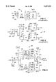
- FIG. 3 shows a circuit according to the present invention.
- FIG. 3 shows a circuit 300 for selectively accomplishing the booth multiplication operation of any of equations (3) to (6) using input values "a" and "b" without using an extra adder before performing booth multiplication.
- Circuit 300 includes an inverter 350 which (i) receives signals representing bits b[3:0] (e.g., 1001) on bus 351 and (ii) selectively inverts the bits b[3:0] based on an inverter select signal on inverter select line 352 sent by a controller 380. Circuit 300 outputs signals representing the inverted bits b'[3:0] (e.g., 0110) on respective lines 362-365 of bus 361 if inverter 350 is selected, or outputs the original bits b[3:0] (e.g., 1001) if inverter 350 is not selected.
- inverter 350 receives signals representing bits b[3:0] (e.g., 1001) on bus 351 and (ii) selectively inverts the bits b[3:0] based on an inverter select signal on inverter select line 352 sent by a controller 380. Circuit 300 outputs signals representing the inverted bits b'[3:0] (e.g.,
- Controller 380 asserts an affirmative inverter select signal on inverter select line 352 when controller 380 determines that the operation of equation (5) or (6) is to be performed. Controller 380 negates the inverter select signal on inverter select line 352 when controller determines that the operation of equation (3) or (4) is to be performed.
- Booth recoder 310 receives signals representing values b[1:0] or b'[1:0] on respective lines 364 and 365 and an increment select signal representing bit b[-1] on increment select line 366.
- a controller 390 asserts an increment select signal on increment select line 366 when controller 390 determines that equation (4) or (6) is to be performed and negates the increment select signal on increment select line 366 when controller 390 determines that equation (3) or (5) is to be performed.
- Booth recoder 310 outputs bits NEG 1 , ZERO 1 , and TWO 1 , over respective lines 311-313 to PPG 320 which receives a signal representing bits a[4:0] on line 375.
- PPG 320 outputs a signal representing partial product PP1 on line 321, as defined in Table 1, for "i” equals 1.
- booth recoder 330 receives signals representing values b[3:1] on respective lines 362-364 and outputs bits NEG 2 , ZERO 2 , and TWO 2 over respective lines 331-333 to PPG 340 which outputs partial product PP2 on line 341 in accordance with Table 1, for "i” equals 2.
- signals TWOC, ONEC, ZERO, ONE, TWO, and MINUS are provided over six lines 311-316 from booth recoder 310 to PPG 320 and over six lines 331-336 from booth recoder 330 to PPG 340 according to Table 2.
- Table 2 shows the output partial products PPi as a function of input bits b[2i-1:2i-3] and bits TWOC, ONEC, ZERO, ONE, TWO, and MINUS, respectively.
- "w a " is the weight of the least significant bit a[0] of value "a”
- "w b " is the weight of the least significant bit b[0] of value "b”.
- PPG 320 receives partial product PP1 for input values b[1:-1]
- bit b[-1] which represents the increment select bit.
- "i" can take the integer value of 1 or 2 since "n" equals 3, PP1 is equal to aw a w b . Since w a and w b are each equal to one in the above example and since b[1:-1] is equal to "010", Table 1 or 2 provides that the first partial product PP1 is equal to 2 0 (11100)(1)(1) or 11100. Therefore, a first partial product PP1 of the radix-4 multiplication is provided as follows: ##EQU3##
- Adder 370 receives the partial products PP1 and PP2 represented by the signals output from PPG 320 and PPG 340, respectively, and produces a signal representing a final product ("product") on line 371.
- the product on line 371 depends on the value represented on the inverter select line 352 and the value represented on the increment select line 366 in accordance with Table 3.
- "a” is the value represented by the input signal on line 315
- "b” is the value represented by the input signal on bus 351.
- circuit 300 is a system for selectively performing the multiplication of equations (3), (4), (5), and (6) in booth multiplication without using an adder before booth recoding, thereby providing a substantial savings in processing time and space and providing flexibility of operation.
- multiplicand and multiplier can be any length.
- n is 7 which results in four booth recoders (i.e., "i” is the set of 1, 2, 3, and 4) or "n” is 8 which results in five booth recoders (i.e., "i” is the set of 1, 2, 3, 4, and 5).
- busses may be performed by lines in serial mode and the function of lines may be accomplished by busses in parallel mode.
Abstract
Description
              TABLE 1
______________________________________
Values of   Value of
Bits b[2i-1:2i-3]
            NEG, ZERO, TWO  PPG Output
Respectively
            Respectively    (PPi)
______________________________________
0, 0, 0     1, 1, 0           zero
0, 0, 1     0, 0, 0         2.sup.(2i-2) aw.sub.a   w.sub.b
0, 1, 0     0, 0, 0         2.sup.(2i-2) aw.sub.a   w.sub.b
0, 1, 1     0, 0, 1         2.sup.(2i-1) aw.sub.a w.  sub.b
1, 0, 0     1, 0, 1         (-1)2.sup.(2i-1) aw.sub.a   w.sub.b
1, 0, 1     1, 0, 0         (-1)2.sup.(2i-2) aw.sub.a   w.sub.b
1, 1, 0     1, 0, 0         (-1)2.sup.(2i-2) aw.sub.a w.  sub.b
1, 1, 1     0, 1, 0         zero
______________________________________
product=a×-b (1)
-b=b'+W.sub.b (2)
product=a×b (3)
product=a×(b+w.sub.b) (4)
product=a×b' (5)
product=a×-b (6)
              TABLE 2
______________________________________
            Value of
            TWOC, ONEC
Values of   ZERO, ONE
Bits b[2i-1:2i-3]
            TWO, and MINUS  PPG output
Respectively
            Respectively    (PPi)
______________________________________
0, 0, 0     0, 0, 1, 0, 0, 0
                            zero
0, 0, 1     0, 0, 0, 1, 0, 0
                            2.sup.(2i-2) aw.sub.a w.sub.b
0, 1, 0     0, 0, 0, 1, 0, 0
                            2.sup.(2i-2) aw.sub.a w.sub.b
0, 1, 1     0, 0, 0, 0, 1, 0
                            2.sup.(2i-1) aw.sub.a w.sub.b
1, 0, 0     1, 0, 0, 0, 0, 1
                            (-1)2.sup.(2i-1) aw.sub.a w.sub.b
1, 0, 1     0, 1, 0, 0, 0, 1
                            (-1)2.sup.(2i-2) aw.sub.a w.sub.b
1, 1, 0     0, 1, 0, 0, 0, 1
                            (-1)2.sup.(2i-2) aw.sub.a w.sub.b
1, 1, 1     0, 0, 1, 0, 0, 0
                            zero
______________________________________
TABLE 3 ______________________________________ Inverter IncrementSelect Select Line 352Line 366 Selected? Selected? Product ______________________________________ NO NO a × b NO YES a × (b + w.sub.b) Yes NO a × b' Yes YES a × -b ______________________________________
Claims (5)
______________________________________
       b[3:1]
             c[5:0]
______________________________________
       0, 0, 0
             0, 0, 1, 0, 0, 0
       0, 0, 1
             0, 0, 0, 1, 0, 0
       0, 1, 0
             0, 0, 0, 1, 0, 0
       0, 1, 1
             0, 0, 0, 0, 1, 0
       1, 0, 0
             1, 0, 0, 0, 0, 1
       1, 0, 1
             0, 1, 0, 0, 0, 1
       1, 1, 0
             0, 1, 0, 0, 0, 1
       1, 1, 1
              0, 0, 1, 0, 0, 0.
______________________________________
______________________________________
c[5:0]         partial products
______________________________________
0, 0, 1, 0, 0, 0
               zero
0, 0, 0, 1, 0, 0
               4a
0, 0, 0, 1, 0, 0
               4a
0, 0, 0, 0, 1, 0
               8a
1, 0, 0, 0, 0, 1
               -8a
0, 1, 0, 0, 0, 1
               -4a
0, 1, 0, 0, 0, 1
               -4a
0, 0, 1, 0, 0, 0
               zero
______________________________________
______________________________________
       b[3:1]
             partial products
______________________________________
       0, 0, 0
             zero
       0, 0, 1
             4a
       0, 1, 0
             4a
       0, 1, 1
             8a
       1, 0, 0
             -8a
       1, 0, 1
             -4a
       1, 1, 0
             -4a
       1, 1, 1
             zero
______________________________________
Priority Applications (1)
| Application Number | Priority Date | Filing Date | Title |
|---|---|---|---|
| US09/099,575 US6167422A (en) | 1998-06-19 | 1998-06-19 | Booth multiplication structure which selectively integrates the function of either of incrementing or negating with the function of booth multiplication |
Applications Claiming Priority (1)
| Application Number | Priority Date | Filing Date | Title |
|---|---|---|---|
| US09/099,575 US6167422A (en) | 1998-06-19 | 1998-06-19 | Booth multiplication structure which selectively integrates the function of either of incrementing or negating with the function of booth multiplication |
Publications (1)
| Publication Number | Publication Date |
|---|---|
| US6167422A true US6167422A (en) | 2000-12-26 |
Family
ID=22275661
Family Applications (1)
| Application Number | Title | Priority Date | Filing Date |
|---|---|---|---|
| US09/099,575 Expired - Lifetime US6167422A (en) | 1998-06-19 | 1998-06-19 | Booth multiplication structure which selectively integrates the function of either of incrementing or negating with the function of booth multiplication |
Country Status (1)
| Country | Link |
|---|---|
| US (1) | US6167422A (en) |
Cited By (4)
| Publication number | Priority date | Publication date | Assignee | Title |
|---|---|---|---|---|
| US6684236B1 (en) * | 2000-02-15 | 2004-01-27 | Conexant Systems, Inc. | System of and method for efficiently performing computations through extended booth encoding of the operands thereto |
| US20070192399A1 (en) * | 2006-02-15 | 2007-08-16 | Shankar Krithivasan | Power-efficient sign extension for booth multiplication methods and systems |
| US20070192398A1 (en) * | 2006-02-15 | 2007-08-16 | Shankar Krithivasan | Booth multiplier with enhanced reduction tree circuitry |
| US20130159367A1 (en) * | 2011-12-19 | 2013-06-20 | Lsi Corporation | Implementation of Negation in a Multiplication Operation Without Post-Incrementation |
Citations (3)
| Publication number | Priority date | Publication date | Assignee | Title |
|---|---|---|---|---|
| US5485413A (en) * | 1993-09-24 | 1996-01-16 | Nec Corporation | Multiplier utilizing the booth algorithm |
| US5677863A (en) * | 1996-04-04 | 1997-10-14 | Hewlett-Packard Co. | Method of performing operand increment in a booth recoded multiply array |
| US5892698A (en) * | 1996-04-04 | 1999-04-06 | Hewlett-Packard Company | 2's complement floating-point multiply accumulate unit |
-
1998
- 1998-06-19 US US09/099,575 patent/US6167422A/en not_active Expired - Lifetime
Patent Citations (3)
| Publication number | Priority date | Publication date | Assignee | Title |
|---|---|---|---|---|
| US5485413A (en) * | 1993-09-24 | 1996-01-16 | Nec Corporation | Multiplier utilizing the booth algorithm |
| US5677863A (en) * | 1996-04-04 | 1997-10-14 | Hewlett-Packard Co. | Method of performing operand increment in a booth recoded multiply array |
| US5892698A (en) * | 1996-04-04 | 1999-04-06 | Hewlett-Packard Company | 2's complement floating-point multiply accumulate unit |
Cited By (7)
| Publication number | Priority date | Publication date | Assignee | Title |
|---|---|---|---|---|
| US6684236B1 (en) * | 2000-02-15 | 2004-01-27 | Conexant Systems, Inc. | System of and method for efficiently performing computations through extended booth encoding of the operands thereto |
| US20070192399A1 (en) * | 2006-02-15 | 2007-08-16 | Shankar Krithivasan | Power-efficient sign extension for booth multiplication methods and systems |
| US20070192398A1 (en) * | 2006-02-15 | 2007-08-16 | Shankar Krithivasan | Booth multiplier with enhanced reduction tree circuitry |
| US7797366B2 (en) | 2006-02-15 | 2010-09-14 | Qualcomm Incorporated | Power-efficient sign extension for booth multiplication methods and systems |
| US7809783B2 (en) * | 2006-02-15 | 2010-10-05 | Qualcomm Incorporated | Booth multiplier with enhanced reduction tree circuitry |
| US20130159367A1 (en) * | 2011-12-19 | 2013-06-20 | Lsi Corporation | Implementation of Negation in a Multiplication Operation Without Post-Incrementation |
| US8892621B2 (en) * | 2011-12-19 | 2014-11-18 | Lsi Corporation | Implementation of negation in a multiplication operation without post-incrementation |
Similar Documents
| Publication | Publication Date | Title |
|---|---|---|
| US3100835A (en) | Selecting adder | |
| US5280439A (en) | Apparatus for determining booth recoder input control signals | |
| US6609143B1 (en) | Method and apparatus for arithmetic operation | |
| US5426598A (en) | Adder and multiplier circuit employing the same | |
| US4745570A (en) | Binary multibit multiplier | |
| EP0152046A2 (en) | Multiplying circuit | |
| US5784305A (en) | Multiply-adder unit | |
| US4807175A (en) | Booth's multiplier | |
| US4868778A (en) | Speed enhancement for multipliers using minimal path algorithm | |
| US6018758A (en) | Squarer with diagonal row merged into folded partial product array | |
| US4366549A (en) | Multiplier with index transforms modulo a prime or modulo a fermat prime and the fermat prime less one | |
| EP0137386B1 (en) | Digital multiplying circuit | |
| US5260889A (en) | Computation of sticky-bit in parallel with partial products in a floating point multiplier unit | |
| US5177703A (en) | Division circuit using higher radices | |
| Stelling et al. | Implementing multiply-accumulate operation in multiplication time | |
| US6167422A (en) | Booth multiplication structure which selectively integrates the function of either of incrementing or negating with the function of booth multiplication | |
| US6260056B1 (en) | Circuit and method for fast squaring by breaking the square into a plurality of terms | |
| US5289399A (en) | Multiplier for processing multi-valued data | |
| US5477479A (en) | Multiplying system having multi-stages for processing a digital signal based on the Booth's algorithm | |
| US5870322A (en) | Multiplier to selectively perform unsigned magnitude multiplication or signed magnitude multiplication | |
| EP0332215B1 (en) | Operation circuit based on floating-point representation | |
| JP3660075B2 (en) | Dividing device | |
| CN114860193A (en) | Hardware operation circuit for calculating Power function and data processing method | |
| US20070180014A1 (en) | Sparce-redundant fixed point arithmetic modules | |
| US5954791A (en) | Multipliers with a shorter run time |
Legal Events
| Date | Code | Title | Description |
|---|---|---|---|
| AS | Assignment |
Owner name: CHROMATIC RESEARCH, INC., CALIFORNIA Free format text: ASSIGNMENT OF ASSIGNORS INTEREST;ASSIGNORS:PURCELL, STEPHEN CLARK;PATWA, NITAL PANKAJKUMAR;REEL/FRAME:009256/0606 Effective date: 19980618 |
|
| AS | Assignment |
Owner name: ATI RESEARCH SILICON VALLEY INC., CALIFORNIA Free format text: CHANGE OF NAME;ASSIGNOR:CHROMATIC RESEARCH, INC.;REEL/FRAME:010226/0012 Effective date: 19990129 |
|
| AS | Assignment |
Owner name: ATI TECHNOLOGIES INC., CANADA Free format text: ASSIGNMENT OF ASSIGNORS INTEREST;ASSIGNOR:ATI RESEARCH SILICON VALLEY INC.;REEL/FRAME:010206/0952 Effective date: 19990811 |
|
| AS | Assignment |
Owner name: ATI INTERNATIONAL SRL, BARBADOS Free format text: ASSIGNMENT OF ASSIGNORS INTEREST;ASSIGNOR:ATI TECHNOLOGIES, INC.;REEL/FRAME:010226/0984 Effective date: 19990813 |
|
| STCF | Information on status: patent grant |
Free format text: PATENTED CASE |
|
| FPAY | Fee payment |
Year of fee payment: 4 |
|
| FPAY | Fee payment |
Year of fee payment: 8 |
|
| AS | Assignment |
Owner name: ATI TECHNOLOGIES ULC, CANADA Free format text: ASSIGNMENT OF ASSIGNORS INTEREST;ASSIGNOR:ATI INTERNATIONAL SRL;REEL/FRAME:023574/0593 Effective date: 20091118 Owner name: ATI TECHNOLOGIES ULC,CANADA Free format text: ASSIGNMENT OF ASSIGNORS INTEREST;ASSIGNOR:ATI INTERNATIONAL SRL;REEL/FRAME:023574/0593 Effective date: 20091118 |
|
| FPAY | Fee payment |
Year of fee payment: 12 |