US6166929A - CSI based drive having active damping control - Google Patents
CSI based drive having active damping control Download PDFInfo
- Publication number
- US6166929A US6166929A US09/515,289 US51528900A US6166929A US 6166929 A US6166929 A US 6166929A US 51528900 A US51528900 A US 51528900A US 6166929 A US6166929 A US 6166929A
- Authority
- US
- United States
- Prior art keywords
- current
- reference current
- pattern generator
- damping
- voltage
- Prior art date
- Legal status (The legal status is an assumption and is not a legal conclusion. Google has not performed a legal analysis and makes no representation as to the accuracy of the status listed.)
- Expired - Lifetime
Links
- 238000013016 damping Methods 0.000 title claims abstract description 60
- 239000003990 capacitor Substances 0.000 claims abstract description 53
- 230000006698 induction Effects 0.000 claims abstract description 14
- 241000246142 Chamaecytisus Species 0.000 claims description 25
- 230000015572 biosynthetic process Effects 0.000 claims description 6
- 238000010586 diagram Methods 0.000 description 14
- 230000001052 transient effect Effects 0.000 description 7
- 230000000694 effects Effects 0.000 description 6
- 238000005070 sampling Methods 0.000 description 5
- 230000010355 oscillation Effects 0.000 description 4
- 238000000034 method Methods 0.000 description 3
- 230000004907 flux Effects 0.000 description 2
- 238000009499 grossing Methods 0.000 description 2
- 230000004044 response Effects 0.000 description 2
- 230000033228 biological regulation Effects 0.000 description 1
- 230000008859 change Effects 0.000 description 1
- 230000008030 elimination Effects 0.000 description 1
- 238000003379 elimination reaction Methods 0.000 description 1
- 230000002708 enhancing effect Effects 0.000 description 1
- 239000000945 filler Substances 0.000 description 1
- 238000010438 heat treatment Methods 0.000 description 1
- 230000003993 interaction Effects 0.000 description 1
- 230000001629 suppression Effects 0.000 description 1
Images
Classifications
-
- H—ELECTRICITY
- H02—GENERATION; CONVERSION OR DISTRIBUTION OF ELECTRIC POWER
- H02P—CONTROL OR REGULATION OF ELECTRIC MOTORS, ELECTRIC GENERATORS OR DYNAMO-ELECTRIC CONVERTERS; CONTROLLING TRANSFORMERS, REACTORS OR CHOKE COILS
- H02P5/00—Arrangements specially adapted for regulating or controlling the speed or torque of two or more electric motors
- H02P5/74—Arrangements specially adapted for regulating or controlling the speed or torque of two or more electric motors controlling two or more AC dynamo-electric motors
-
- H—ELECTRICITY
- H02—GENERATION; CONVERSION OR DISTRIBUTION OF ELECTRIC POWER
- H02M—APPARATUS FOR CONVERSION BETWEEN AC AND AC, BETWEEN AC AND DC, OR BETWEEN DC AND DC, AND FOR USE WITH MAINS OR SIMILAR POWER SUPPLY SYSTEMS; CONVERSION OF DC OR AC INPUT POWER INTO SURGE OUTPUT POWER; CONTROL OR REGULATION THEREOF
- H02M5/00—Conversion of AC power input into AC power output, e.g. for change of voltage, for change of frequency, for change of number of phases
- H02M5/40—Conversion of AC power input into AC power output, e.g. for change of voltage, for change of frequency, for change of number of phases with intermediate conversion into DC
- H02M5/42—Conversion of AC power input into AC power output, e.g. for change of voltage, for change of frequency, for change of number of phases with intermediate conversion into DC by static converters
- H02M5/44—Conversion of AC power input into AC power output, e.g. for change of voltage, for change of frequency, for change of number of phases with intermediate conversion into DC by static converters using discharge tubes or semiconductor devices to convert the intermediate DC into AC
- H02M5/443—Conversion of AC power input into AC power output, e.g. for change of voltage, for change of frequency, for change of number of phases with intermediate conversion into DC by static converters using discharge tubes or semiconductor devices to convert the intermediate DC into AC using devices of a thyratron or thyristor type requiring extinguishing means
- H02M5/45—Conversion of AC power input into AC power output, e.g. for change of voltage, for change of frequency, for change of number of phases with intermediate conversion into DC by static converters using discharge tubes or semiconductor devices to convert the intermediate DC into AC using devices of a thyratron or thyristor type requiring extinguishing means using semiconductor devices only
- H02M5/4505—Conversion of AC power input into AC power output, e.g. for change of voltage, for change of frequency, for change of number of phases with intermediate conversion into DC by static converters using discharge tubes or semiconductor devices to convert the intermediate DC into AC using devices of a thyratron or thyristor type requiring extinguishing means using semiconductor devices only having a rectifier with controlled elements
Definitions
- the invention generally relates to the field of power electronics. Conjointly, the invention also relates to a drive for an alternating current (a.c.) induction motor which employs a current source inverter and features improved voltage regulation and suppressed resonance between the drive and motor.
- a.c. alternating current
- the improved drive is suitable for high power multi-motor applications.
- Pulse width modulated current source inverter (CSI) based a.c. motor drives are increasingly used in high power (e.g., 1,000-10,000 hp) applications. See, for instance, P. M. Espelage and J. M. Nowak, "Symmetrical GTO Current Source Inverter for Wide Speed Range Control of 2300 to 4160 volt, 350 to 7000 hp, Induction Motors", IEEE IAS Annual Meeting, pp302-307, 1988.
- the CSI drive Compared with voltage source inverter fed drives, the CSI drive features simple structure, reliable short circuit protection, four quadrant operation capability and nearly sinusoidal output voltage and current waveforms.
- GTO gate turn-off thyristor
- the CSI drive is not problem-free.
- the CSI drive with a single a.c. induction motor there exists a resonance mode due to the parallel connection of the output filter capacitor and the motor. This makes it difficult to stabilize the system if the drive operates at a frequency which is close to the resonant frequency.
- Further details concerning this problem can be found in the following two references, both of which are incorporated herein in their entirety: B. Wu, F. DeWinter, "Elimination of Harmonic Resonance in High Power GTO-CSI Induction Motor Drives", IEEE PESC Conf. pp1011-1015, 1015, 1994; and R. Itoh, "Stability of Induction Motor Drive Controlled by Current-source Inverter", IEE Proc. Vol. 136, Pt. B, No. 2, pp83-88, 1989.
- the situation becomes even worse when the motor is unloaded since the inverter output current in this case is minimal whereas the resonant current flowing between the capacitor and the motor magnetizing inductance is substantial.
- a similar resonance problem also exists when a PWM rectifier is employed in the drive to provide direct current to the CSI from a power source.
- a resonance mode exists between an input a.c. filter capacitor of the rectifier and the system impedance of the line voltage source. If the resonance frequency is close to a characteristic harmonic of the rectifier an oscillation will occur, which makes the stability of the PWM rectifier sensitive to the system impedance. Unfortunately it is difficult to measure the system impedance accurately, which complicates the design of a compensating filter.
- the resonance frequency is not close to any characteristic harmonic of the rectifier, undesired oscillations will also occur during transient states. See additionally, N. R. Zargari, G. Joos, and P. D. Ziogas, "Input Filter Design for PWM Current-Source Rectifiers", IEEE Trans. on Ind. Appl., vol. 30, No. 6, pp1573-1579, 1994.
- the motors connected to the inverter may have different sizes, which may produce multiple resonant modes. The effect of these and other resonant modes on drive stability should be minimized, and the drive should be able to operate steadily over a full speed range.
- the inverter output voltage should be kept constant both in steady and transient states for a given output frequency. In other words, the inverter output voltage should be stiff, not affected by changes in multiple motor loads. Otherwise an interaction between the motors and inverter will occur when one or more motors are loaded or unloaded, making the system unstable.
- the invention seeks to overcome various of these problems.
- One aspect of the invention reduces the resonance existing between one or more output filter capacitors of a current source inverter and an a.c. induction motor. This is achieved through the use of active damping control, wherein the invention essentially simulates the use of a physical damping resistor connected in parallel with each output capacitor. This is accomplished by determining how much current would flow through the resistor had it been there, and this current, which is equal to the voltage across the output filter capacitor divided by the value of the resistor, is deducted from a command or reference current used to control the inverter. From a control point of view, the invention provides damping similar to the use of a real damping resistor, but without the corresponding energy loss.
- an inverter which includes a switching bridge for converting direct current into alternating current.
- the direct current is coupled to a line side of the switching bridge and the alternating current is provided at a load side of the switching bridge.
- a switching pattern generator controls switches in the switching bridge based on a reference current.
- At least one capacitor is connected at a terminal thereof to the load side of the switching bridge. The terminal is connectable to a load having an inductance, such as an a.c. induction motor. Control circuitry connected to the switching pattern generator
- the active damping control may also be applied to a pulse width modulated (PWM) rectifier to reduce resonance caused between one or more input a.c. shunt capacitors of the PWM rectifier and the system impedance of a power source.
- PWM pulse width modulated
- a PWM rectifier which includes a switching bridge for converting alternating current into direct current. The alternating current is coupled to a line side of the switching bridge and the direct current is provided at a load side of the switching bridge.
- a switching pattern generator controls switches in the switching bridge based on a reference current. At least one shunt capacitor is connected at a terminal thereof to the line side of the switching bridge.
- An alternating current power source having a system inductance may be connected to the terminal. Control circuitry connected to the switching pattern generator:
- a drive which comprises a PWM rectifier coupled to a current source inverter via a d.c. link choke.
- the PWM rectifier and the current source inverter each employ active damping control.
- the stability of a CSI-based drive may be enhanced by feedforward control of the d.c. voltage supplied to the inverter.
- a drive for an a.c. induction motor which comprises a rectifier for converting alternating current into direct current and a current source inverter for converting direct current into alternating current supplied to a motor.
- a d.c. link choke interconnects the rectifier and the inverter.
- the inverter includes a first control loop which provides a desired or command d.c. link choke current to a second control loop responsible for the rectifier. For the purposes of the second control loop the actual d.c. link choke current and an input voltage of the inverter are detected.
- the difference or error between the desired and actual d.c. choke currents are minimized by a compensator.
- the output of the compensator is added to the detected inverter input voltage, and the sum is fed to a switching pattern generator which controls the switches in the rectifier. In this manner the feedback of the inverter input voltage is decoupled from the compensator responsible for the d.c. link choke current.
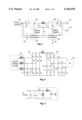
- FIG. 1 is a system block diagram of a CSI-based motor drive
- FIG. 2 is a circuit diagram of a rectifier and an inverter of the drive respectively connected to a power source and a motor;
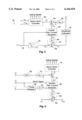
- FIG. 3 is a system block diagram of an inverter controller
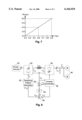
- FIG. 4 is a circuit diagram of a per phase steady state equivalent circuit of the motor
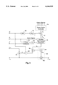
- FIG. 5 is a system block diagram of a rectifier controller
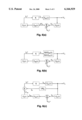
- FIG. 6 is a system block diagram of the drive in the frequency domain when it is configured in (a) a conventional manner, (b) with a physical damping resistor, and (c) with an active damping control block;
- FIG. 7 is a graph showing the relationship between the per unit values of an output filter capacitor and a damping factor at a particular frequency
- FIG. 8 is a system block diagram of a CSI based drive which employs a thyristor rectifier.
- FIG. 9 is a system block diagram of a PWM rectifier controller.
- the detailed description is divided into two parts.
- the first portion of the discussion relates to active damping control in order to suppress resonance modes.
- the second part of the discussion centres on enhancement of the CSI-based drive through the use of feedforward control.
- FIG. 1 shows a schematic block diagram of a drive 20 for control of one or more a.c. induction motors 40.
- the drive 20 comprises a rectifier 24 coupled to a current source inverter 30 via a d.c. link choke or inductor L dc .
- the rectifier 24 converts alternating current supplied from a three-phase power source 22 into direct current which is smoothed by the d.c. link choke L dc , thereby providing a current source for the inverter 30.
- the inverter 30, converts the d.c. current into a three-phase alternating current (which may vary in terms of its frequency as well as magnitude) for supply to the a.c. induction motor 40.
- the current source inverter 30 includes a per phase output filter capacitor C o which is connected to the load side of the inverter for the purpose of smoothing the output voltage and limiting transient voltage spikes during inverter changes of state.
- a per phase input filter capacitor C i may be connected to the line side of the rectifier 24 for the purposes of smoothing the input wave forms.
- the input filter capacitor also limits the total harmonic distortion and improves the power factor of the line voltages and currents, as typically required by the utility company.
- FIG. 2 shows a circuit diagram of the rectifier 24 and inverter 30 as respectively connected to the power source 22 and motor 40.
- the rectifier 24 includes a three phase switching bridge comprising three legs 25 and six switches W 1 -W 6 such as SCRs, GTOs, GCTs, IGCTs, SGCTs, or IGBTs as shown.
- the per phase input capacitors C i ,a, C i ,b and C i ,c are shown connected in delta formation, but may be alternatively connected in a wye formation.
- the inverter 30 includes a three-phase switching bridge comprising three legs 31 and six GCT, IGCT, SGCT, IGBT or GTO switches S 1 -S 6 .
- the per phase output capacitors C o ,a C o ,b and C o ,c are also shown connected in delta formation but may alternatively be connected in wye formation.
- the drive 20 employs a constant hertz-velocity (CHV) or v/f control.
- CHV hertz-velocity
- v/f control This control technique attempts to keep the motor flux constant throughout the majority of the operating range of the motor, since the flux, ⁇ , is related to voltage and frequency as follows: ##EQU1## where k is a constant.
- the output voltage v o is controlled by adjusting the inverter output current i o .
- the drive 20 includes an inverter controller 32 which, is connected to a rectifier controller 26.
- the control loops provided by these blocks may be implemented in practice through the use of a single digital signal processor or other such microprocessor, as preferred.
- analogue circuitry may be used in the alternative.
- the external input or command to the drive is provided by a signal 34 which represents a desired motor operating frequency, f o * that generally or roughly corresponds to the desired rotational speed of the motor.
- a signal 34 which represents a desired motor operating frequency, f o * that generally or roughly corresponds to the desired rotational speed of the motor.
- f o * a desired motor operating frequency
- Such a system can be used, inter alia, in compressor or fan applications where precise speed control is not critical.
- an outer motor speed feed back control loop may be employed (not shown) which outputs the value for signal 34 (although such a system is typically not used with CHV control).
- FIG. 3 shows the inverter controller 32 in greater detail.
- the magnitude of the output voltage v o is determined by an amplitude calculator 42 which generates a scalar output feedback voltage v o '.
- the command operating frequency signal f o * is received by a CHV block 44 which computes a desired or command output voltage amplitude v o * equal to k ⁇ f o *, k being a pre-selected constant. (Note that the applied voltage is, however, typically limited to the rated voltage of the motor when f o * exceeds the rated operating frequency).
- the output voltage amplitude feedback v o ' and the command voltage amplitude v o * are fed into a compensator 47 comprising a summer 46 and a p.i.
- p.i.d. controller 48 whose output is a nominal desired output current amplitude i no set to minimize the error v o *-v o ' (i.e., ⁇ v o ).
- An inverter reference current generator 50 receives the output of the p.i. compensator 47 and the command operating frequency signal f o * and generates a three-phase nominal reference current i no * having frequency f o *, each phase being spaced apart by 120°.
- a summer 54 deducts a three-phase damping current i d from the nominal reference current i no * to generate a three-phase reference current i o *. This quantity is fed into a switching pattern generator such as, but not limited to, a space vector controller 56 as known in the art per se which provides the gating signals to the power switches S 1 -S 6 of the inverter 30.
- the damping current i d provides active damping control of the resonance between each output filler capacitor C o and the motor inductances.
- the motor includes a stator resistance R s , a relatively large magnetizing inductance L m , a relatively small leakage inductance L 1 , and a rotor resistance ##EQU2## whose impedance varies in relation to frequency and load conditions. From FIG. 4 it will be seen that there are two resonance modes caused by the output filter capacitor C o and the motor inductances.
- One is a comparatively high frequency resonance mode due to the output filter capacitor C o and the motor leakage inductance L i .
- the other is a comparatively low frequency resonance associated with the output filter capacitor C o and the motor magnetizing inductance L m .
- the high frequency resonance is usually excited by harmonic currents while the low frequency resonance may fall into the operating frequency range of the motor. If the drive operates at a frequency close to the resonance frequency, it becomes difficult to stabilize the system. For multi-induction motor drives, multiple resonance modes exist which complicate the problem even further.
- the resonance modes may be suitably controlled by connecting a damping resistor R d (shown in phantom) in parallel with the output filter capacitor C o . If the damping resistor R d is adequately small compared to the motor equivalent impedance, the parallel resonance can be sufficiently suppressed. This technique is not practical due to the high power loss caused by the damping resistor, especially in medium voltage applications. However, the damping effect can be simulated without the corresponding power loss, as follows.
- FIGS. 1 and 3 can be simplified as shown in FIG. 6(a), where Z mc (s) represents the transfer function of output filter capacitor C o and induction motor, on a per phase basis.
- G c (s), G PI (s) and G I (s) denote, respectively, the transfer functions of the amplitude calculator 42, the p.i. controller 48, and the inverter reference current generator 50.
- the current source inverter 30 and space vector controller 56 are considered as an ideal linear amplifier with a unity gain K.
- the damping control block 52 is not considered in FIG. 6(a).
- FIG. 6(c) shows a system block diagram which considers the damping factor block 52.
- the inverter output voltage V o (s) in FIG. 6(c) can be expressed as
- the damping factor R d may be selected for particular applications by general adherence to the following steps:
- base values which depend on the total power rating of the multiple motors.
- Three base values are required, which are the base value of impedance Z b , the base value of inductance L b and the base value of capacitor C b .
- Base value calculations are well known in the art; see, for example, W. D. Stevenson, Jr., "Elements of Power System Analysis", 4 th Ed., Mcgraw Hill, N.Y., N.Y., pp. 30-34.
- the per unit values of the leakage inductance L l and the magnetizing inductance L m for each motor can then be calculated based on the upper calculated base values. Then the multiple motors may be combined into one equivalent motor according to the parallel and series connection principles of electric circuits. The equivalent per unit values can then be obtained.
- the switching frequency should be selected. Generally speaking a higher switching frequency implies a higher sampling frequency which results in a better damping effect since a physical resistor can be better approximated. This is subject to the constraint that the switching frequency is usually limited by the power rating of the drive. As a general guideline, it is recommended that the switching frequency be at least 500 Hz.
- the sampling frequency of the digital controller be at least five times as high as the resonance frequency.
- the sampling frequency is three times as high as the switching frequency. For example, if the switching frequency is 500 Hz, the sampling frequency will be 1500 Hz.
- the output filter capacitor may be selected to make the resonance frequency lower than 300 Hz.
- the per unit values of the leakage inductance are typically around 0.15-0.2, which means that a 0.3 per unit output filter capacitor is typically large enough to satisfy this recommendation.
- R d may be selected. In order to achieve an adequate damping effect, it is generally recommended that R d should be equal to or less than 0.5 per unit. According to the base value of impedance Z b , the real value of R d can be obtained.
- FIG. 7 shows the relationship between the per unit value of the capacitor and the damping factor R d when the switching frequency is 500 Hz.
- the rectifier 24 is a PWM rectifier which requires the input filter capacitors C i .
- a high frequency resonance mode also exists between the input filter capacitor C i and a system inductance L s associated with the power supply 22, as seen best in FIG. 2. If this resonance frequency is close to a characteristic harmonic of the rectifier (e.g., 5th or 7th), an oscillation will occur, which makes the stability of the PWM rectifier sensitive to the system impedance. Unfortunately it is difficult to measure the system impedance accurately, which complicates the design of a compensating filter. In addition, even when the resonance frequency is not close to any characteristic harmonic of the rectifier, undesired oscillations will also occur during transient states.
- FIG. 5 shows the PWM rectifier controller 26 in greater detail.
- the controller 26 features two control loops, one for control of the d.c. link current i dc , and one for control of the power factor.
- the inverter controller 32 provides the rectifier controller 26 with a desired or command d.c. link current magnitude i* ndc , which generally corresponds to the magnitude of the inverter reference current i o *.
- a compensator 62 comprising a summer 60 and a p.i. controller 64 receive i* ndc and the feedback current i' dc .
- the output of the compensator 64 is a nominal rectifier input current i nr which is fed into a rectifier reference current generator 66.
- the generator 66 produces a 120° three phase nominal reference current i nr * having magnitude i nr , at the line frequency.
- the PWM rectifier controller 26 also includes active damping control in order to suppress the high frequency resonance between the input filter capacitor C i and the system inductance L s of the power supply.
- a high pass filter 68 allows the higher frequency harmonics of the rectifier input voltage v i to pass through a 1/R d damping block 70.
- Block 70 produces a three phase damping current i d which is deducted by a summer 72 from the nominal rectifier reference current i d to produce a rectifier reference current i r *.
- a second switching pattern generator such as space vector controller 74 generates the gating signal for the power switches W 1 -W 6 of the PWM rectifier.
- the power factor control loop attempts to provide a unity power factor relative to the line source, i.e., it is desired that is be in phase with v s (see FIG. 1).
- the current i C .sbsb.i through the input filter capacitor C i will generally lead the voltage v i .
- This may be accomplished by detecting the phase difference between i s and v s at block 76. If the output of the phase detector 76 is not zero, this represents an error which is compensated for by a p.i. controller 78 whose output is a phase angle ⁇ .
- the rectifier reference current generator 66 establishes i nr * with a phase angle relative to v s equal to ⁇ .
- rectifier 24 as a PWM rectifier.
- the drive 20 can be implemented using other types of rectifiers, such as a thyristor rectifier, with or without a d.c. chopper such as a multilevel buck chopper.
- the PWM rectifier is preferred, however, because it has a better dynamic performance than the thyristor rectifier, and is more suitable in terms of power loss in medium voltage applications than d.c. choppers.
- the switching pattern generator for the rectifier or inverter has been shown as a space vector controller, those skilled in the art will understand that the invention is not limited to such a commutation technique. Rather, the limiting factor is whether the switching pattern generator can reasonably be considered as a linear amplifier, not taking into account switching harmonics.
- FIG. 8 shows another version of a CSI based a.c. induction motor drive.
- a phase controlled thyristor rectifier 24' as known in the art per se is employed.
- the output of p.i. controller 64 is a voltage which is fed into a switching pattern generator 82 that provides the gating signals to the thyristors of the rectifier 24'.
- the illustrated embodiment may or may not employ active damping control for the current source inverter, although it is preferred for the reasons described above.
- the average value of the rectifier output voltage v dc will be equal to that of the inverter input voltage v in .
- the rectifier output voltage v dc will have two components, namely a voltage drop on the d.c. link choke L dc and the inverter input voltage v in .
- the voltage drop on the d.c. link choke is caused by the fact that in transient conditions, the current flow through the d.c. link choke cannot abruptly change. This causes a problem in the dynamic performance of the rectifier since the output voltage v dc cannot closely follow the changes of the inverter input voltage, yielding a sluggish response.
- the illustrated embodiment employs a rectifier input voltage feedforward control loop.
- the inverter controller 32 calculates the inverter side d.c. voltage v in based on the inverter output voltage v o and the currently active switches. For example, referring to FIG. 2, assume that in a given sampling period T s switches S 1 and S 2 are on for a duration t i and switches S 1 and S 6 are on for a duration t j . In this case the average value of the inverter side d.c.
- the inverter side d.c. voltage v in can be measured through the use of an additional sensor to thereby provide a different means for determining the inverter side d.c. voltage.
- the calculated or measured voltage, v in ' can be used as a part of the d.c. voltage reference, v* dc , employed by switching pattern generator 82, that is,
- v pi is the output of the d.c. link current p.i. controller 64.
- a summer 80 adds the output of the p.i. controller 64 with v in ', and the output of the summer is fed to the switching pattern generator 80.
- the v in feedforward control has an added feature.
- the output of the p.i. controller represents the voltage drop on the d.c. link choke. This implies that the design of the d.c. link current p.i. controller is mainly associated with L dc , independent of other system parameters.
- the parameters of the p.i. controller may be difficult to determine since the inverter side d.c. voltage v in will depend on the load. This is undesireable, particulalry for multi-motor applications.
- the v in feedforward control may also be applied in circumstances where the drive employs a PWM rectifier which employs a switching pattern generator based on a current reference signal.
- the measured or calculated value v in ' can be multiplied by a multiplier 90 with the measured d.c. link current i dc to determine the active power P' flowing through the inverter. Since the d.c. link choke L dC will ideally not consume any active power, the active power flowing through the rectifier 24' should be the same.
- the transient component of the rectifier current i r (on a per phase basis) arising as a result of the inverter side d.c. voltage v in can be computed by ##EQU7## as provided by a divider 92.
- the multiplier and divider may be thought of as forming part of the means for determining the inverter side d.c. voltage, but which provides a current based output signal rather than a voltage based output signal.
- a summer 94 adds the output of the p.i. controller 64 with the current-based output signal of the divider 92 to determine the nominal rectifier reference current i nr .
Landscapes
- Engineering & Computer Science (AREA)
- Power Engineering (AREA)
- Inverter Devices (AREA)
Abstract
Description
V.sub.o (s)=(I.sub.no *(s)-I.sub.d (s))·K·Z.sub.mc (s)[1]
v.sub.dc *=v.sub.in '+v.sub.pi [ 5]
Claims (24)
Priority Applications (1)
| Application Number | Priority Date | Filing Date | Title |
|---|---|---|---|
| US09/515,289 US6166929A (en) | 2000-02-29 | 2000-02-29 | CSI based drive having active damping control |
Applications Claiming Priority (1)
| Application Number | Priority Date | Filing Date | Title |
|---|---|---|---|
| US09/515,289 US6166929A (en) | 2000-02-29 | 2000-02-29 | CSI based drive having active damping control |
Publications (1)
| Publication Number | Publication Date |
|---|---|
| US6166929A true US6166929A (en) | 2000-12-26 |
Family
ID=24050731
Family Applications (1)
| Application Number | Title | Priority Date | Filing Date |
|---|---|---|---|
| US09/515,289 Expired - Lifetime US6166929A (en) | 2000-02-29 | 2000-02-29 | CSI based drive having active damping control |
Country Status (1)
| Country | Link |
|---|---|
| US (1) | US6166929A (en) |
Cited By (79)
| Publication number | Priority date | Publication date | Assignee | Title |
|---|---|---|---|---|
| US6304046B1 (en) * | 1999-10-05 | 2001-10-16 | Samsung Electronics Co., Ltd. | Driving control circuit of a hood motor |
| US20020089864A1 (en) * | 2001-01-10 | 2002-07-11 | Gabor Kalman | Ac-to-ac power converter without a dc link capacitor |
| US6437996B1 (en) * | 1998-10-05 | 2002-08-20 | Aloys Wobben | Electrical power transmission system |
| US6472844B2 (en) * | 2000-03-21 | 2002-10-29 | Koninklijke Philips Electronics N.V. | Single-phased powered drive system |
| US6549438B2 (en) | 2001-04-30 | 2003-04-15 | Precision Automation, Inc. | AC-to-DC converter circuit utilizing IGBT's for improved efficiency |
| US6559654B2 (en) | 2001-03-29 | 2003-05-06 | General Electric Company | Method and system for automatic determination of inductance |
| US6583598B2 (en) * | 2000-11-29 | 2003-06-24 | Siemens Aktiengesellschaft | Damping of resonant peaks in an electric motor which is operated using a converter with an intermediate voltage circuit, by means of matched impedance to ground at the motor star point, and a corresponding electric motor |
| US20030132727A1 (en) * | 2002-01-17 | 2003-07-17 | Kabushiki Kaisha Meidensha | Permanent magnet synchronous motor driving system, and method of testing permanent magnet synchronous motor driving system |
| US6617814B1 (en) | 2001-04-11 | 2003-09-09 | Rockwell Automation Technologies, Inc. | Integrated DC link choke and method for suppressing common-mode voltage in a motor drive |
| US6642689B2 (en) * | 2001-02-13 | 2003-11-04 | Hitachi, Ltd. | Control apparatus for power converter |
| US20030222459A1 (en) * | 2002-05-31 | 2003-12-04 | Martyn Harris | Capacitive control of alternator regulation |
| US20040027208A1 (en) * | 2002-08-06 | 2004-02-12 | General Electric Company | Method and apparatus for damping an LC filter |
| US6747373B1 (en) * | 2001-12-26 | 2004-06-08 | Abb Technology Ag | System and method for coordinated control of a switched power capacitor with an integrated resonance protection system |
| US20050013145A1 (en) * | 2003-07-19 | 2005-01-20 | Norbert Huber | Converter with damping mechanism for the avoidance of resonances |
| US6850424B2 (en) * | 2001-09-21 | 2005-02-01 | Siemens Aktiengesellschaft | Inverter with a line-side and load-side freewheeling pulse converter using SiC switching elements |
| US6987372B1 (en) | 2001-04-11 | 2006-01-17 | Rockwell Automation Technologies, Inc. | Integrated DC link choke and method for suppressing common-mode voltage in a motor drive |
| US20060245216A1 (en) * | 2005-04-15 | 2006-11-02 | Rockwell Automation, Inc. | DC voltage balance control for three-level NPC power converters with even-order harmonic elimination scheme |
| US7132812B1 (en) | 2001-04-11 | 2006-11-07 | Rockwell Automation Technologies, Inc. | Integrated DC link choke and method for suppressing common-mode voltage in a motor drive |
| US20060267542A1 (en) * | 2005-05-27 | 2006-11-30 | Lixiang Wei | Pulse width modulation (PWM) rectifier with variable switching frequency |
| US20060267527A1 (en) * | 2005-05-26 | 2006-11-30 | Khopkar Rahul V | System, apparatus and method for driving permanent magnet electrical machine |
| GB2437845A (en) * | 2006-05-05 | 2007-11-07 | Gen Electric | Resistive Torsional Mode Damping System And Method |
| US20070279947A1 (en) * | 2004-07-05 | 2007-12-06 | Siemens Aktiengesellschaft | High-Voltage Direct-Current Transmission Device |
| US20080007385A1 (en) * | 2006-07-10 | 2008-01-10 | Rockwell Automation Technologies, Inc. | Methods and apparatus for flux dispersal in link inductor |
| US20090175061A1 (en) * | 2008-01-04 | 2009-07-09 | Milan Rajne | Instantaneous load current control scheme for voltage fed dc to ac inverter supplying resistive-inductive load |
| US20100025995A1 (en) * | 2008-07-31 | 2010-02-04 | Rockwell Automation Technologies, Inc. | Current source converter-based wind energy system |
| RU2381606C2 (en) * | 2004-07-05 | 2010-02-10 | Сименс Акциенгезелльшафт | Dc high-voltage power transmission device |
| US20100080028A1 (en) * | 2008-09-29 | 2010-04-01 | Rockwell Automation Technologies, Inc. | Power conversion system and method for active damping of common mode resonance |
| US20100148581A1 (en) * | 2008-12-12 | 2010-06-17 | Sudhir Kumar Gupta | Power system and method for driving an electromotive traction system and auxiliary equipment through a common power bus |
| US20100165674A1 (en) * | 2008-12-30 | 2010-07-01 | Rockwell Automation Technologies, Inc. | Power conversion systems and methods for controlling harmonic distortion |
| CN102223094A (en) * | 2010-04-16 | 2011-10-19 | 通用电气公司 | Power conversion system and LC circuit damping method |
| US20110310642A1 (en) * | 2010-06-21 | 2011-12-22 | Rockwell Automation Technologies, Inc. | Low cost current source converters for power generation application |
| US8223511B2 (en) | 2010-06-07 | 2012-07-17 | Rockwell Automation Technologies, Inc. | Common mode voltage reduction apparatus and method for current source converter based drive |
| US8259426B2 (en) | 2010-05-28 | 2012-09-04 | Rockwell Automation Technologies, Inc. | Variable frequency drive and methods for filter capacitor fault detection |
| US8295063B2 (en) | 2011-04-05 | 2012-10-23 | General Electric Company | System and method for damping LC circuits in power conversion systems |
| US20120314467A1 (en) * | 2010-12-22 | 2012-12-13 | O'brien Kathleen Ann | Power conversion system and method |
| CN101944337B (en) * | 2009-07-03 | 2013-01-16 | 乐金显示有限公司 | Liquid crystal display |
| US8471514B2 (en) | 2010-09-30 | 2013-06-25 | Rockwell Automation Technologies, Inc. | Adaptive harmonic reduction apparatus and methods |
| US20130314064A1 (en) * | 2010-12-17 | 2013-11-28 | Ams Ag | Control loop arrangement, circuit arrangement and method of regulating a load-coupled current source and the supply voltage therefor |
| US8810182B2 (en) | 2010-09-30 | 2014-08-19 | Rockwell Automation Technologies, Inc. | Adaptive harmonic reduction apparatus and methods |
| US8816625B2 (en) | 2011-10-27 | 2014-08-26 | Rockwell Automation Technologies, Inc. | Integrated regenerative AC drive with solid state precharging |
| US20140328091A1 (en) * | 2011-09-26 | 2014-11-06 | Kenichi Sakakibara | Power converter |
| US20140376283A1 (en) * | 2013-06-21 | 2014-12-25 | Hamilton Sundstrand Corporation | Systems and methods for active damping device for stabilizing a power grid of active sources and loads |
| US20140376284A1 (en) * | 2013-06-21 | 2014-12-25 | Hamilton Sundstrand Corporation | Systems and methods for tuning the control of a shunt active power filter over a variable frequency |
| US9041327B2 (en) | 2013-06-12 | 2015-05-26 | Rockwell Automation Technologies, Inc. | Method and apparatus for overvoltage protection and reverse motor speed control for motor drive power loss events |
| US9054589B2 (en) | 2010-05-28 | 2015-06-09 | Rockwell Automation Technologies, Inc. | Method and apparatus for detecting power converter capacitor degradation using negative sequence currents |
| US9083274B2 (en) | 2013-04-08 | 2015-07-14 | Rockwell Automation Technologies, Inc. | Power stage precharging and dynamic braking apparatus for multilevel inverter |
| US20150217646A1 (en) * | 2012-09-11 | 2015-08-06 | Bombardier Transportation Gmbh | Circuit Arrangement and Method of Operating a Circuit Arrangement |
| US20160079902A1 (en) * | 2014-09-17 | 2016-03-17 | Control Techniques Limited | Inverter drives having a controlled power output |
| US9294005B2 (en) | 2013-10-01 | 2016-03-22 | Rockwell Automation Technologies, Inc. | Method and apparatus for detecting AFE filter capacitor degradation |
| US9318944B2 (en) | 2013-04-29 | 2016-04-19 | Rockwell Automation Technologies, Inc. | Methods and apparatus for active front end filter capacitor degradation detection |
| US9325252B2 (en) | 2014-01-13 | 2016-04-26 | Rockwell Automation Technologies, Inc. | Multilevel converter systems and sinusoidal pulse width modulation methods |
| US9362839B2 (en) | 2011-02-09 | 2016-06-07 | Rockwell Automation Technologies, Inc. | Power converter with common mode voltage reduction |
| US9389263B2 (en) | 2014-06-05 | 2016-07-12 | Rockwell Automation Technologies, Inc. | Filter capacitor degradation identification using measured and expected voltage |
| US9425705B2 (en) | 2012-08-13 | 2016-08-23 | Rockwell Automation Technologies, Inc. | Method and apparatus for bypassing cascaded H-bridge (CHB) power cells and power sub cell for multilevel inverter |
| US9490690B2 (en) | 2014-03-11 | 2016-11-08 | Rockwell Automation Technologies, Inc. | Filter capacitor degradation identification using computed power |
| US9488686B2 (en) | 2014-02-24 | 2016-11-08 | Rockwell Automation Technologies, Inc. | Filter capacitor degradation identification using computed current |
| US20160359423A1 (en) * | 2014-02-19 | 2016-12-08 | Daikin Industries, Ltd. | Method of controlling power conversion apparatus |
| US9520800B2 (en) | 2014-01-09 | 2016-12-13 | Rockwell Automation Technologies, Inc. | Multilevel converter systems and methods with reduced common mode voltage |
| US9559541B2 (en) | 2015-01-15 | 2017-01-31 | Rockwell Automation Technologies, Inc. | Modular multilevel converter and charging circuit therefor |
| US9651592B2 (en) | 2013-12-03 | 2017-05-16 | Rockwell Automation Technologies, Inc. | Impedance detector apparatus and method |
| US9653984B2 (en) | 2012-04-30 | 2017-05-16 | Rockwell Automation Technologies, Inc. | Filter capacitor degradation detection apparatus and method |
| US9667128B2 (en) | 2012-04-30 | 2017-05-30 | Rockwell Automation Technologies, Inc. | Power converter resonance detection apparatus and method |
| US9735696B2 (en) | 2015-11-25 | 2017-08-15 | Rockwell Automation Technologies, Inc. | Filter capacitor degradation and calibration |
| US9748862B2 (en) | 2015-05-13 | 2017-08-29 | Rockwell Automation Technologies, Inc. | Sparse matrix multilevel actively clamped power converter |
| US9787210B2 (en) | 2015-01-14 | 2017-10-10 | Rockwell Automation Technologies, Inc. | Precharging apparatus and power converter |
| US9787213B2 (en) | 2013-03-18 | 2017-10-10 | Rockwell Automation Technologies, Inc. | Power cell bypass method and apparatus for multilevel inverter |
| US9800134B2 (en) | 2015-02-25 | 2017-10-24 | Rockwell Automation Technologies, Inc. | Motor drive with LCL filter inductor with built-in passive damping resistor for AFE rectifier |
| US9812990B1 (en) | 2016-09-26 | 2017-11-07 | Rockwell Automation Technologies, Inc. | Spare on demand power cells for modular multilevel power converter |
| US9837924B1 (en) | 2016-06-02 | 2017-12-05 | Rockwell Automation Technologies, Inc. | Precharge apparatus for power conversion system |
| EP2043241B1 (en) * | 2007-09-28 | 2017-12-27 | Rockwell Automation Technologies, Inc. | Motor Drive Using Flux Adjustment to Control Power Factor |
| US9923469B2 (en) | 2016-05-09 | 2018-03-20 | Rockwell Automation Technologies, Inc. | Motor drive filter damping |
| RU2661479C1 (en) * | 2017-06-07 | 2018-07-17 | Илья Николаевич Джус | Dc power transmission substation |
| US10158299B1 (en) | 2018-04-18 | 2018-12-18 | Rockwell Automation Technologies, Inc. | Common voltage reduction for active front end drives |
| US20200112280A1 (en) * | 2018-10-05 | 2020-04-09 | Steering Solutions Ip Holding Corporation | Dynamic estimation of supply current for electric motor drive |
| US10826322B2 (en) | 2013-06-14 | 2020-11-03 | Abb Schweiz Ag | Systems and methods for grid interactive UPS |
| US11025052B2 (en) | 2018-01-22 | 2021-06-01 | Rockwell Automation Technologies, Inc. | SCR based AC precharge protection |
| US11211879B2 (en) * | 2019-09-23 | 2021-12-28 | Rockwell Automation Technologies, Inc. | Capacitor size reduction and lifetime extension for cascaded H-bridge drives |
| US11342878B1 (en) | 2021-04-09 | 2022-05-24 | Rockwell Automation Technologies, Inc. | Regenerative medium voltage drive (Cascaded H Bridge) with reduced number of sensors |
| CN117394673A (en) * | 2023-09-22 | 2024-01-12 | 珠海市伟高变频科技有限公司 | PFC control method and system for inhibiting voltage and current resonance of weak current network |
Citations (3)
| Publication number | Priority date | Publication date | Assignee | Title |
|---|---|---|---|---|
| US4066938A (en) * | 1976-10-06 | 1978-01-03 | General Electric Company | Input current modulation to reduce torque pulsations in controlled current inverter drives |
| US4670827A (en) * | 1985-03-01 | 1987-06-02 | Siemens Aktiengesellschaft | Controlled regenerative D-C power supply |
| US5245522A (en) * | 1990-11-22 | 1993-09-14 | Hitachi, Ltd. | Power supply controlled to supply load current formed as sine wave |
-
2000
- 2000-02-29 US US09/515,289 patent/US6166929A/en not_active Expired - Lifetime
Patent Citations (3)
| Publication number | Priority date | Publication date | Assignee | Title |
|---|---|---|---|---|
| US4066938A (en) * | 1976-10-06 | 1978-01-03 | General Electric Company | Input current modulation to reduce torque pulsations in controlled current inverter drives |
| US4670827A (en) * | 1985-03-01 | 1987-06-02 | Siemens Aktiengesellschaft | Controlled regenerative D-C power supply |
| US5245522A (en) * | 1990-11-22 | 1993-09-14 | Hitachi, Ltd. | Power supply controlled to supply load current formed as sine wave |
Non-Patent Citations (14)
| Title |
|---|
| DeWinter et al., "Medium Voltage Motor Harmonic Heating, Torques and Voltage Stress when Applied on VFDs", IEEE 43rd PCIC Conference, pp. 131-139, 1996 (No Month). |
| DeWinter et al., Medium Voltage Motor Harmonic Heating, Torques and Voltage Stress when Applied on VFDs , IEEE 43 rd PCIC Conference, pp. 131 139, 1996 (No Month). * |
| Espelage et al., "Symmetrical GTO Current Source Inverter for Wide Speed Range Control of 2300 to 4160 Volt, 350 to 7000 HP, Induction Motors", IEEE IAS Annual Meeting, pp. 302-307, 1988, (No Month). |
| Espelage et al., Symmetrical GTO Current Source Inverter for Wide Speed Range Control of 2300 to 4160 Volt, 350 to 7000 HP, Induction Motors , IEEE IAS Annual Meeting, pp. 302 307, 1988, (No Month). * |
| Itoh, "Stability of induction motor drive controlled by current-source inverter", IEE Proceedings, vol. 136, Pt. B, No. 2, pp. 83-88, Mar. 1989. |
| Itoh, Stability of induction motor drive controlled by current source inverter , IEE Proceedings, vol. 136, Pt. B, No. 2, pp. 83 88, Mar. 1989. * |
| Stevenson, Jr., "Elements of Power System Analysis", Fourth Edition, pp. 30-34, McGraw-Hill Book Company, (No Date). |
| Stevenson, Jr., Elements of Power System Analysis , Fourth Edition, pp. 30 34, McGraw Hill Book Company, (No Date). * |
| Trzynadlowski, "Introduction to Modern Power Electronics", pp. 296-323, John Wiley & Sons, Inc. (No Date). |
| Trzynadlowski, Introduction to Modern Power Electronics , pp. 296 323, John Wiley & Sons, Inc. (No Date). * |
| Wu et al., "Elimination of Harmonic Resonance in High Power GTO CSI Induction Motor Drives", pp. 1011-1015, IEEE PESC, 1994, (No Month). |
| Wu et al., Elimination of Harmonic Resonance in High Power GTO CSI Induction Motor Drives , pp. 1011 1015, IEEE PESC, 1994, (No Month). * |
| Zargari et al., "Input Filter Design for PWM Current-Source Rectifiers", IEEE Trans. on Ind. Appl. vol. 30, No. 6, pp. 1573-1579, 1994, (No Month). |
| Zargari et al., Input Filter Design for PWM Current Source Rectifiers , IEEE Trans. on Ind. Appl. vol. 30, No. 6, pp. 1573 1579, 1994, (No Month). * |
Cited By (119)
| Publication number | Priority date | Publication date | Assignee | Title |
|---|---|---|---|---|
| US6437996B1 (en) * | 1998-10-05 | 2002-08-20 | Aloys Wobben | Electrical power transmission system |
| US6304046B1 (en) * | 1999-10-05 | 2001-10-16 | Samsung Electronics Co., Ltd. | Driving control circuit of a hood motor |
| US6472844B2 (en) * | 2000-03-21 | 2002-10-29 | Koninklijke Philips Electronics N.V. | Single-phased powered drive system |
| US6583598B2 (en) * | 2000-11-29 | 2003-06-24 | Siemens Aktiengesellschaft | Damping of resonant peaks in an electric motor which is operated using a converter with an intermediate voltage circuit, by means of matched impedance to ground at the motor star point, and a corresponding electric motor |
| US6839249B2 (en) * | 2001-01-10 | 2005-01-04 | Honeywell International Inc. | AC-to-ac power converter without a dc link capacitor |
| WO2002056451A3 (en) * | 2001-01-10 | 2003-07-03 | Honeywell Int Inc | Ac-to-ac power converter without a dc link capacitor |
| US20020089864A1 (en) * | 2001-01-10 | 2002-07-11 | Gabor Kalman | Ac-to-ac power converter without a dc link capacitor |
| US6642689B2 (en) * | 2001-02-13 | 2003-11-04 | Hitachi, Ltd. | Control apparatus for power converter |
| US6559654B2 (en) | 2001-03-29 | 2003-05-06 | General Electric Company | Method and system for automatic determination of inductance |
| US7132812B1 (en) | 2001-04-11 | 2006-11-07 | Rockwell Automation Technologies, Inc. | Integrated DC link choke and method for suppressing common-mode voltage in a motor drive |
| US6617814B1 (en) | 2001-04-11 | 2003-09-09 | Rockwell Automation Technologies, Inc. | Integrated DC link choke and method for suppressing common-mode voltage in a motor drive |
| US6987372B1 (en) | 2001-04-11 | 2006-01-17 | Rockwell Automation Technologies, Inc. | Integrated DC link choke and method for suppressing common-mode voltage in a motor drive |
| US6549438B2 (en) | 2001-04-30 | 2003-04-15 | Precision Automation, Inc. | AC-to-DC converter circuit utilizing IGBT's for improved efficiency |
| US6850424B2 (en) * | 2001-09-21 | 2005-02-01 | Siemens Aktiengesellschaft | Inverter with a line-side and load-side freewheeling pulse converter using SiC switching elements |
| US6747373B1 (en) * | 2001-12-26 | 2004-06-08 | Abb Technology Ag | System and method for coordinated control of a switched power capacitor with an integrated resonance protection system |
| US6870347B2 (en) * | 2002-01-17 | 2005-03-22 | Kabushiki Kaisha Meidensha | Permanent magnet synchronous motor driving system, and method of testing permanent magnet synchronous motor driving system |
| US20030132727A1 (en) * | 2002-01-17 | 2003-07-17 | Kabushiki Kaisha Meidensha | Permanent magnet synchronous motor driving system, and method of testing permanent magnet synchronous motor driving system |
| US7215098B2 (en) | 2002-05-31 | 2007-05-08 | Bowman Power Systems Ltd. | Electrical generating system having capacitative control of alternator regulation |
| WO2003103111A1 (en) * | 2002-05-31 | 2003-12-11 | Bowman Power Systems Limited | High-frequency generator |
| US20030222459A1 (en) * | 2002-05-31 | 2003-12-04 | Martyn Harris | Capacitive control of alternator regulation |
| US6765452B2 (en) * | 2002-08-06 | 2004-07-20 | General Electric Company | Method and apparatus for damping an LC filter |
| US20040027208A1 (en) * | 2002-08-06 | 2004-02-12 | General Electric Company | Method and apparatus for damping an LC filter |
| US20050013145A1 (en) * | 2003-07-19 | 2005-01-20 | Norbert Huber | Converter with damping mechanism for the avoidance of resonances |
| US7019990B2 (en) * | 2003-07-19 | 2006-03-28 | Dr. Johannes Heidenhain Gmbh | Converter with damping mechanism for the avoidance of resonances |
| AU2005262096B2 (en) * | 2004-07-05 | 2010-03-11 | Siemens Aktiengesellschaft | High-voltage direct-current transmission device |
| CN101069334B (en) * | 2004-07-05 | 2011-03-09 | 西门子公司 | Devices for HVDC transmission |
| US20070279947A1 (en) * | 2004-07-05 | 2007-12-06 | Siemens Aktiengesellschaft | High-Voltage Direct-Current Transmission Device |
| RU2381606C2 (en) * | 2004-07-05 | 2010-02-10 | Сименс Акциенгезелльшафт | Dc high-voltage power transmission device |
| US7495938B2 (en) | 2005-04-15 | 2009-02-24 | Rockwell Automation Technologies, Inc. | DC voltage balance control for three-level NPC power converters with even-order harmonic elimination scheme |
| US20060245216A1 (en) * | 2005-04-15 | 2006-11-02 | Rockwell Automation, Inc. | DC voltage balance control for three-level NPC power converters with even-order harmonic elimination scheme |
| US20060267527A1 (en) * | 2005-05-26 | 2006-11-30 | Khopkar Rahul V | System, apparatus and method for driving permanent magnet electrical machine |
| US7190143B2 (en) * | 2005-05-27 | 2007-03-13 | Rockwell Automation Technologies, Inc. | Pulse width modulation (PWM) rectifier with variable switching frequency |
| US20060267542A1 (en) * | 2005-05-27 | 2006-11-30 | Lixiang Wei | Pulse width modulation (PWM) rectifier with variable switching frequency |
| GB2437845A (en) * | 2006-05-05 | 2007-11-07 | Gen Electric | Resistive Torsional Mode Damping System And Method |
| US20070279012A1 (en) * | 2006-05-05 | 2007-12-06 | Sihler Christof M | Resistive torsional mode damping system and method |
| US7423411B2 (en) | 2006-05-05 | 2008-09-09 | General Electric Company | Resistive torsional mode damping system and method |
| GB2437845B (en) * | 2006-05-05 | 2011-08-17 | Gen Electric | Resistive torsional mode damping system and method |
| US20080007385A1 (en) * | 2006-07-10 | 2008-01-10 | Rockwell Automation Technologies, Inc. | Methods and apparatus for flux dispersal in link inductor |
| US7692524B2 (en) | 2006-07-10 | 2010-04-06 | Rockwell Automation Technologies, Inc. | Methods and apparatus for flux dispersal in link inductor |
| EP2043241B1 (en) * | 2007-09-28 | 2017-12-27 | Rockwell Automation Technologies, Inc. | Motor Drive Using Flux Adjustment to Control Power Factor |
| US20090175061A1 (en) * | 2008-01-04 | 2009-07-09 | Milan Rajne | Instantaneous load current control scheme for voltage fed dc to ac inverter supplying resistive-inductive load |
| US7852646B2 (en) * | 2008-01-04 | 2010-12-14 | Honeywell International Inc. | Instantaneous load current control scheme for voltage fed DC to AC inverter supplying resistive-inductive load |
| US8030791B2 (en) | 2008-07-31 | 2011-10-04 | Rockwell Automation Technologies, Inc. | Current source converter-based wind energy system |
| US8350397B2 (en) | 2008-07-31 | 2013-01-08 | Rockwell Automation Technologies, Inc. | Current source converter-based wind energy system |
| US20100025995A1 (en) * | 2008-07-31 | 2010-02-04 | Rockwell Automation Technologies, Inc. | Current source converter-based wind energy system |
| US20100080028A1 (en) * | 2008-09-29 | 2010-04-01 | Rockwell Automation Technologies, Inc. | Power conversion system and method for active damping of common mode resonance |
| US7990097B2 (en) | 2008-09-29 | 2011-08-02 | Rockwell Automation Technologies, Inc. | Power conversion system and method for active damping of common mode resonance |
| US7928597B2 (en) * | 2008-12-12 | 2011-04-19 | General Electric Company | Power system and method for driving an electromotive traction system and auxiliary equipment through a common power bus |
| US20100148581A1 (en) * | 2008-12-12 | 2010-06-17 | Sudhir Kumar Gupta | Power system and method for driving an electromotive traction system and auxiliary equipment through a common power bus |
| US20100165674A1 (en) * | 2008-12-30 | 2010-07-01 | Rockwell Automation Technologies, Inc. | Power conversion systems and methods for controlling harmonic distortion |
| US8044631B2 (en) | 2008-12-30 | 2011-10-25 | Rockwell Automation Technologies, Inc. | Power conversion systems and methods for controlling harmonic distortion |
| CN101944337B (en) * | 2009-07-03 | 2013-01-16 | 乐金显示有限公司 | Liquid crystal display |
| CN102223094A (en) * | 2010-04-16 | 2011-10-19 | 通用电气公司 | Power conversion system and LC circuit damping method |
| EP2395651A2 (en) | 2010-04-16 | 2011-12-14 | General Electric Company | System and method for damping lc circuits in power conversion systems |
| CN102223094B (en) * | 2010-04-16 | 2014-04-09 | 通用电气公司 | Power conversion system and LC circuit damping method |
| US8259426B2 (en) | 2010-05-28 | 2012-09-04 | Rockwell Automation Technologies, Inc. | Variable frequency drive and methods for filter capacitor fault detection |
| US8937796B2 (en) | 2010-05-28 | 2015-01-20 | Rockwell Automation Technologies, Inc. | Variable frequency drive and methods for filter capacitor fault detection |
| US9054589B2 (en) | 2010-05-28 | 2015-06-09 | Rockwell Automation Technologies, Inc. | Method and apparatus for detecting power converter capacitor degradation using negative sequence currents |
| US8223511B2 (en) | 2010-06-07 | 2012-07-17 | Rockwell Automation Technologies, Inc. | Common mode voltage reduction apparatus and method for current source converter based drive |
| CN102709933A (en) * | 2010-06-21 | 2012-10-03 | 洛克威尔自动控制技术股份有限公司 | Low cost current source converters for power generation application |
| US20110310642A1 (en) * | 2010-06-21 | 2011-12-22 | Rockwell Automation Technologies, Inc. | Low cost current source converters for power generation application |
| US8698335B2 (en) * | 2010-06-21 | 2014-04-15 | Rockwell Automation Technologies, Inc. | Low cost current source converters for power generation application |
| US8810182B2 (en) | 2010-09-30 | 2014-08-19 | Rockwell Automation Technologies, Inc. | Adaptive harmonic reduction apparatus and methods |
| US8471514B2 (en) | 2010-09-30 | 2013-06-25 | Rockwell Automation Technologies, Inc. | Adaptive harmonic reduction apparatus and methods |
| US20130314064A1 (en) * | 2010-12-17 | 2013-11-28 | Ams Ag | Control loop arrangement, circuit arrangement and method of regulating a load-coupled current source and the supply voltage therefor |
| US9158316B2 (en) * | 2010-12-17 | 2015-10-13 | Ams Ag | Control loop arrangement, circuit arrangement and method of regulating a load-coupled current source and the supply voltage therefor |
| US8705256B2 (en) * | 2010-12-22 | 2014-04-22 | General Electric Company | Power conversion system and method for converting DC power at a DC bus into AC power |
| US20120314467A1 (en) * | 2010-12-22 | 2012-12-13 | O'brien Kathleen Ann | Power conversion system and method |
| US9362839B2 (en) | 2011-02-09 | 2016-06-07 | Rockwell Automation Technologies, Inc. | Power converter with common mode voltage reduction |
| US8295063B2 (en) | 2011-04-05 | 2012-10-23 | General Electric Company | System and method for damping LC circuits in power conversion systems |
| US20140328091A1 (en) * | 2011-09-26 | 2014-11-06 | Kenichi Sakakibara | Power converter |
| US9246398B2 (en) * | 2011-09-26 | 2016-01-26 | Daikin Industries, Ltd. | Power converter |
| US8816625B2 (en) | 2011-10-27 | 2014-08-26 | Rockwell Automation Technologies, Inc. | Integrated regenerative AC drive with solid state precharging |
| US9667128B2 (en) | 2012-04-30 | 2017-05-30 | Rockwell Automation Technologies, Inc. | Power converter resonance detection apparatus and method |
| US9653984B2 (en) | 2012-04-30 | 2017-05-16 | Rockwell Automation Technologies, Inc. | Filter capacitor degradation detection apparatus and method |
| US9912221B2 (en) | 2012-08-13 | 2018-03-06 | Rockwell Automation Technologies, Inc. | Method and apparatus for bypassing cascaded h-bridge (CHB) power cells and power sub cell for multilevel inverter |
| US10305368B2 (en) | 2012-08-13 | 2019-05-28 | Rockwell Automation Technologies, Inc. | Method and apparatus for bypassing Cascaded H-Bridge (CHB) power cells and power sub cell for multilevel inverter |
| US9425705B2 (en) | 2012-08-13 | 2016-08-23 | Rockwell Automation Technologies, Inc. | Method and apparatus for bypassing cascaded H-bridge (CHB) power cells and power sub cell for multilevel inverter |
| US20150217646A1 (en) * | 2012-09-11 | 2015-08-06 | Bombardier Transportation Gmbh | Circuit Arrangement and Method of Operating a Circuit Arrangement |
| US9694702B2 (en) * | 2012-09-11 | 2017-07-04 | Bombardier Transportation Gmbh | Circuit arrangement and method of operating a circuit arrangement |
| US9787213B2 (en) | 2013-03-18 | 2017-10-10 | Rockwell Automation Technologies, Inc. | Power cell bypass method and apparatus for multilevel inverter |
| US9083274B2 (en) | 2013-04-08 | 2015-07-14 | Rockwell Automation Technologies, Inc. | Power stage precharging and dynamic braking apparatus for multilevel inverter |
| US9318944B2 (en) | 2013-04-29 | 2016-04-19 | Rockwell Automation Technologies, Inc. | Methods and apparatus for active front end filter capacitor degradation detection |
| US9041327B2 (en) | 2013-06-12 | 2015-05-26 | Rockwell Automation Technologies, Inc. | Method and apparatus for overvoltage protection and reverse motor speed control for motor drive power loss events |
| US10826322B2 (en) | 2013-06-14 | 2020-11-03 | Abb Schweiz Ag | Systems and methods for grid interactive UPS |
| US11289940B2 (en) | 2013-06-14 | 2022-03-29 | Abb Schweiz Ag | Systems and methods for multi-use multi-mode ups |
| US9225172B2 (en) * | 2013-06-21 | 2015-12-29 | Hamilton Sundstrand Corporation | Systems and methods for tuning the control of a shunt active power filter over a variable frequency |
| US20140376283A1 (en) * | 2013-06-21 | 2014-12-25 | Hamilton Sundstrand Corporation | Systems and methods for active damping device for stabilizing a power grid of active sources and loads |
| US20140376284A1 (en) * | 2013-06-21 | 2014-12-25 | Hamilton Sundstrand Corporation | Systems and methods for tuning the control of a shunt active power filter over a variable frequency |
| US9294005B2 (en) | 2013-10-01 | 2016-03-22 | Rockwell Automation Technologies, Inc. | Method and apparatus for detecting AFE filter capacitor degradation |
| US9651592B2 (en) | 2013-12-03 | 2017-05-16 | Rockwell Automation Technologies, Inc. | Impedance detector apparatus and method |
| US9520800B2 (en) | 2014-01-09 | 2016-12-13 | Rockwell Automation Technologies, Inc. | Multilevel converter systems and methods with reduced common mode voltage |
| US9325252B2 (en) | 2014-01-13 | 2016-04-26 | Rockwell Automation Technologies, Inc. | Multilevel converter systems and sinusoidal pulse width modulation methods |
| US9735698B2 (en) * | 2014-02-19 | 2017-08-15 | Daikin Industries, Ltd. | Method of controlling power conversion apparatus |
| US20160359423A1 (en) * | 2014-02-19 | 2016-12-08 | Daikin Industries, Ltd. | Method of controlling power conversion apparatus |
| US9488686B2 (en) | 2014-02-24 | 2016-11-08 | Rockwell Automation Technologies, Inc. | Filter capacitor degradation identification using computed current |
| US9490690B2 (en) | 2014-03-11 | 2016-11-08 | Rockwell Automation Technologies, Inc. | Filter capacitor degradation identification using computed power |
| US9389263B2 (en) | 2014-06-05 | 2016-07-12 | Rockwell Automation Technologies, Inc. | Filter capacitor degradation identification using measured and expected voltage |
| US20170207740A1 (en) * | 2014-09-17 | 2017-07-20 | Nidec Control Techniques Limited | Inverter drives having a controlled power output |
| US20160079902A1 (en) * | 2014-09-17 | 2016-03-17 | Control Techniques Limited | Inverter drives having a controlled power output |
| US9647592B2 (en) * | 2014-09-17 | 2017-05-09 | Nidec Control Techniques Limited | Inverter drives having a controlled power output |
| US9906180B2 (en) * | 2014-09-17 | 2018-02-27 | Nidec Control Techniques Limited | Inverter drives having a controlled power output |
| US9787210B2 (en) | 2015-01-14 | 2017-10-10 | Rockwell Automation Technologies, Inc. | Precharging apparatus and power converter |
| US9559541B2 (en) | 2015-01-15 | 2017-01-31 | Rockwell Automation Technologies, Inc. | Modular multilevel converter and charging circuit therefor |
| US9800134B2 (en) | 2015-02-25 | 2017-10-24 | Rockwell Automation Technologies, Inc. | Motor drive with LCL filter inductor with built-in passive damping resistor for AFE rectifier |
| US9748862B2 (en) | 2015-05-13 | 2017-08-29 | Rockwell Automation Technologies, Inc. | Sparse matrix multilevel actively clamped power converter |
| US9735696B2 (en) | 2015-11-25 | 2017-08-15 | Rockwell Automation Technologies, Inc. | Filter capacitor degradation and calibration |
| US9923469B2 (en) | 2016-05-09 | 2018-03-20 | Rockwell Automation Technologies, Inc. | Motor drive filter damping |
| US9837924B1 (en) | 2016-06-02 | 2017-12-05 | Rockwell Automation Technologies, Inc. | Precharge apparatus for power conversion system |
| US9812990B1 (en) | 2016-09-26 | 2017-11-07 | Rockwell Automation Technologies, Inc. | Spare on demand power cells for modular multilevel power converter |
| RU2661479C1 (en) * | 2017-06-07 | 2018-07-17 | Илья Николаевич Джус | Dc power transmission substation |
| US11025052B2 (en) | 2018-01-22 | 2021-06-01 | Rockwell Automation Technologies, Inc. | SCR based AC precharge protection |
| US10158299B1 (en) | 2018-04-18 | 2018-12-18 | Rockwell Automation Technologies, Inc. | Common voltage reduction for active front end drives |
| US20200112280A1 (en) * | 2018-10-05 | 2020-04-09 | Steering Solutions Ip Holding Corporation | Dynamic estimation of supply current for electric motor drive |
| US10833620B2 (en) * | 2018-10-05 | 2020-11-10 | Steering Solutions Ip Holding Corporation | Dynamic estimation of supply current for electric motor drive |
| US11211879B2 (en) * | 2019-09-23 | 2021-12-28 | Rockwell Automation Technologies, Inc. | Capacitor size reduction and lifetime extension for cascaded H-bridge drives |
| US11342878B1 (en) | 2021-04-09 | 2022-05-24 | Rockwell Automation Technologies, Inc. | Regenerative medium voltage drive (Cascaded H Bridge) with reduced number of sensors |
| CN117394673A (en) * | 2023-09-22 | 2024-01-12 | 珠海市伟高变频科技有限公司 | PFC control method and system for inhibiting voltage and current resonance of weak current network |
| CN117394673B (en) * | 2023-09-22 | 2024-03-22 | 珠海市伟高变频科技有限公司 | PFC control method and system for inhibiting voltage and current resonance of weak current network |
Similar Documents
| Publication | Publication Date | Title |
|---|---|---|
| US6166929A (en) | CSI based drive having active damping control | |
| US6269010B1 (en) | CSI based drive having feedforward control of inverter input voltage | |
| US6366483B1 (en) | PWM rectifier having de-coupled power factor and output current control loops | |
| Malesani et al. | AC/DC/AC PWM converter with reduced energy storage in the DC link | |
| JP2583258B2 (en) | Method and apparatus for electrostatic power conversion | |
| Lee et al. | Control of single-phase-to-three-phase AC/DC/AC PWM converters for induction motor drives | |
| US6295215B1 (en) | AC power supply apparatus with economy mode and methods of operation thereof | |
| US5977660A (en) | Active harmonic filter and power factor corrector | |
| US5561595A (en) | Power inverter with input line conditioning | |
| Sul et al. | Design and performance of a high-frequency link induction motor drive operating at unity power factor | |
| US5121314A (en) | Bi-mode high voltage resonant power supply and method | |
| EP3479652A1 (en) | High frequency high power converter system | |
| KR950035037A (en) | Control circuit for inductive load | |
| CA2041753C (en) | Procedure for regulating the d.c. voltage of a rectifier | |
| US5905644A (en) | DC bus voltage controller | |
| Serpa et al. | A modified direct power control strategy allowing the connection of three-phase inverter to the grid through LCL filters | |
| JPH0638711B2 (en) | DC power supply for inverter | |
| US4473790A (en) | Control circuit for suppression of line resonances in current feedback pulse width modulation control systems with a minimum d-c filter | |
| Stankovic et al. | A generalized control method for input-output harmonic elimination for the PWM boost rectifier under simultaneous unbalanced input voltages and input impedances | |
| US4933828A (en) | Control system for voltage-source pulse width modulation step-up rectifier | |
| US7042194B1 (en) | Controller for a wound-rotor induction motor | |
| Qiu et al. | High performance current source inverter fed induction motor drive with minimal harmonic distortion | |
| Malesani et al. | AC/DC/AC PWM converter with minimum energy storage in the DC link | |
| US7477531B2 (en) | Compensation circuit for use with a three-phase drive powering a single-phase load | |
| JPS58141699A (en) | Motor controller |
Legal Events
| Date | Code | Title | Description |
|---|---|---|---|
| AS | Assignment |
Owner name: ALLEN-BRADLEY COMPANY, LLC, WISCONSIN Free format text: ASSIGNMENT OF ASSIGNORS INTEREST;ASSIGNORS:MA, DAMING;WU, BIN;ZARGARI, NAVID R.;AND OTHERS;REEL/FRAME:010658/0143 Effective date: 20000224 |
|
| STCF | Information on status: patent grant |
Free format text: PATENTED CASE |
|
| FEPP | Fee payment procedure |
Free format text: PAYOR NUMBER ASSIGNED (ORIGINAL EVENT CODE: ASPN); ENTITY STATUS OF PATENT OWNER: LARGE ENTITY |
|
| FPAY | Fee payment |
Year of fee payment: 4 |
|
| FPAY | Fee payment |
Year of fee payment: 8 |
|
| FPAY | Fee payment |
Year of fee payment: 12 |