US6161647A - Fall arresting ladder safety device - Google Patents
Fall arresting ladder safety device Download PDFInfo
- Publication number
- US6161647A US6161647A US09/236,705 US23670599A US6161647A US 6161647 A US6161647 A US 6161647A US 23670599 A US23670599 A US 23670599A US 6161647 A US6161647 A US 6161647A
- Authority
- US
- United States
- Prior art keywords
- side rail
- ladder
- ladder side
- arms
- fall arresting
- Prior art date
- Legal status (The legal status is an assumption and is not a legal conclusion. Google has not performed a legal analysis and makes no representation as to the accuracy of the status listed.)
- Expired - Fee Related
Links
- 241001503987 Clematis vitalba Species 0.000 abstract description 36
- 230000009194 climbing Effects 0.000 abstract description 16
- 230000001174 ascending effect Effects 0.000 abstract description 2
- 238000007373 indentation Methods 0.000 description 4
- 230000007246 mechanism Effects 0.000 description 3
- 229910000831 Steel Inorganic materials 0.000 description 2
- 238000000034 method Methods 0.000 description 2
- 238000012986 modification Methods 0.000 description 2
- 230000004048 modification Effects 0.000 description 2
- 239000010959 steel Substances 0.000 description 2
- 230000009471 action Effects 0.000 description 1
- 238000011161 development Methods 0.000 description 1
- 230000036541 health Effects 0.000 description 1
- 230000008569 process Effects 0.000 description 1
- 238000011160 research Methods 0.000 description 1
- 238000005096 rolling process Methods 0.000 description 1
- 125000006850 spacer group Chemical group 0.000 description 1
- 238000012360 testing method Methods 0.000 description 1
Images


Classifications
-
- A—HUMAN NECESSITIES
- A62—LIFE-SAVING; FIRE-FIGHTING
- A62B—DEVICES, APPARATUS OR METHODS FOR LIFE-SAVING
- A62B35/00—Safety belts or body harnesses; Similar equipment for limiting displacement of the human body, especially in case of sudden changes of motion
- A62B35/0043—Lifelines, lanyards, and anchors therefore
- A62B35/0062—Rail-form lifelines for permanent installation
-
- A—HUMAN NECESSITIES
- A62—LIFE-SAVING; FIRE-FIGHTING
- A62B—DEVICES, APPARATUS OR METHODS FOR LIFE-SAVING
- A62B1/00—Devices for lowering persons from buildings or the like
- A62B1/06—Devices for lowering persons from buildings or the like by making use of rope-lowering devices
- A62B1/14—Devices for lowering persons from buildings or the like by making use of rope-lowering devices with brakes sliding on the rope
-
- E—FIXED CONSTRUCTIONS
- E06—DOORS, WINDOWS, SHUTTERS, OR ROLLER BLINDS IN GENERAL; LADDERS
- E06C—LADDERS
- E06C7/00—Component parts, supporting parts, or accessories
- E06C7/18—Devices for preventing persons from falling
- E06C7/186—Rail or rope for guiding a safety attachment, e.g. a fall arrest system
- E06C7/187—Guiding rail
Definitions
- This invention relates generally to fall arresting ladder safety devices, and more particularly to fall arresting ladder safety devices that attach to a ladder side rail rather than a rigid carrier rail or carrier cable extending along the centerline of the ladder.
- Conventional fall arresting ladder safety systems such as those sold under the trademarks Saf-T-Climb®, a registered trademark of Siebe North Inc., and Lad-Saf®, a registered trademark of D B Industries, Inc., include a carrier device which is attached to a rigid carrier rail or a carrier cable for movement therealong.
- the carrier rail or cable extends vertically along the length of the ladder and is disposed a distance outward from the ladder rungs along the centerline thereof.
- a lanyard typically six feet (1.8 meters) in length is connected at one end to the carrier device with the other end connected to the body harness of the climber. As the climber ascends or descends the ladder, the carrier device is pulled along the carrier rail or cable with the climber.
- the carrier device lockably engages the rigid carrier rail or cable such that the climber will only free fall the distance of the length of the lanyard.
- the climber's free fall is arrested after only a short distance.
- each fixed ladder must be specially equipped with the special carrier rail or cable and one or more carrier devices. Equipping ladders with these special carrier rails or cables and carrier devices can be quite expensive, especially if the site or facility on which the system is installed is greater than 50 feet in height requiring a series of offset ladders and landings or rest platforms.
- a fall arresting ladder safety device for attachment to a fixed ladder side rail.
- the fall arresting device is to be used in conjunction with a body harness worn by the climber with a lanyard attached at one end to the body harness and the other end attached to the fall arresting device.
- the fall arresting device includes first and second arms pivotally connected in an X-configuration with each arm having first and second ladder side rail engaging portions disposed on opposite edges of the ladder side rail.
- a spring operably attached to the first and second arms biases the first and second arms between a fall arresting position and a climbing position, with the arms being normally biased in the fall arresting position wherein the first and second ladder side rail engaging portions of both first and second arms are lockably engaging the ladder side rail.
- the side rail engaging portions of the first arm are preferably U-shaped channel members with roughened grips that lockably engage the ladder side rail, while the side rail engaging portions of the second arm are preferably rollers that allow the device to roll up and down the ladder side rail.
- the climber keeps one hand on the handle portion of the first arm with the other hand grasping the ladder rungs or opposite side rail.
- the climber pivots the handle portion of the first arm upward to disengage the roughened grips of the U-shaped channel member side rail engaging portions of the first arm, thereby leaving only the rollers of the side rail engaging portions of the second arm engaging the ladder side rail.
- the device is then rolled up or down ahead of the climber as the climber ascends or descends the ladder.
- the arms of the fall arresting device can be locked into a disengaging position such that said fall arresting device can be removed from the ladder side rail for later use on the same or another ladder.
- FIG. 1 is a perspective view showing the preferred embodiment of the fall arresting device of the present invention attached to a side rail of a ladder and being used by a climber;
- FIG. 2 is a perspective view showing the fall arresting device of the present invention supporting a climber that has fallen from the ladder;
- FIG. 3 is a forward perspective view of the preferred embodiment of the fall arresting device of the present invention attached to a ladder side rail;
- FIG. 4 is a rearward perspective view of the preferred embodiment of the fall arresting device of the present invention attached to a ladder side rail;
- FIG. 5 is a top plan view of the of the preferred embodiment of the fall arresting device of the present invention attached to a ladder side rail;
- FIG. 6 is a left side elevation view of the preferred embodiment of the fall arresting device of the present invention attached to a ladder side rail and showing the movement of the device between a first fall arresting position (solid lines) and a second climbing position (dashed lines);
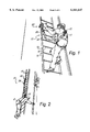
- FIG. 7 is a right side elevation view of the preferred embodiment of the fall arresting device of the present invention attached to a ladder side rail and showing the movement of the device between a first fall arresting position (solid lines) and a second climbing position (dashed lines);
- FIG. 8 is a right side elevation view showing the movement of the arms between the fall arresting position (dashed lines) and the disengaged position (solid lines).
- FIG. 1 shows a ladder safety system (10) being used by a climber (12) climbing a ladder (14) having side rails (16) and rungs (18).
- the ladder safety system (10) of the preferred embodiment is comprised of a fall arresting device (20), a body harness (22), and a lanyard (24).
- the fall arresting device (20) removably attaches to the side rail (16) of the ladder (14).
- the lanyard (24) comprising a rope or chord having quick release clips (25) at each end, removably attaches at one end to the fall arresting device (20) and at the other end to the body harness (22) worn by the climber (12).
- any reference to the body harness (22) is intended to include any type of body restraint worn by a climber (12) for attachment to a lanyard (24) that serves to support the body of the climber (12) from the lanyard (24) in case of a fall.
- FIG. 2 shows the fall arresting device (20) of the present invention supporting the climber (12) from the lanyard (24) after falling from the ladder (14).
- the fall arresting device (20) is lockably engaged on the ladder side rail (16) in the fall arresting position (discussed later).
- the preferred embodiment of the fall arresting device (20) includes first and second arms (26, 28) (FIGS. 3-8) that are pivotally attached to one another in an "X" configuration by a pin (30) (best viewed in FIG. 6) such that each arm (26, 28) is pivotal with respect to the other about the axis of the pin (30) much like the action of a scissors.
- the first arm (26) includes a dog-legged handle portion (32) and first and second ladder side rail engaging portions (34, 36) (FIGS. 5, 7).
- the second arm (28) also includes first and second ladder side rail engaging portions (38, 40) (FIGS. 5, 7).
- An aperture (37) (FIGS. 3, 4) is disposed in the first arm (26) near the handle portion (32) for receiving the quick release clip (25) of the lanyard (24).
- the first arm (26) is preferably fabricated from 3/8 inch steel plate.
- the second arm (28) is preferably fabricated from 12 gauge or 1/8 inch steel plate.
- each of the ladder side rail engaging portions (34, 36) of the first arm (26) and the side rail engaging portions (38, 40) of the second arm (28) are disposed on opposite edges of the ladder side rail (16).
- a coil spring (41) (FIGS. 3, 5, 6), or any other type of biasing means, such as an arm spring, an elastomeric band, or the like, is operably attached to the first and second arms (26, 28), such that the ladder side rail engaging portions (34, 36) of the first arm (26) and the ladder side rail engaging portions (38, 40) of the second arm (28) are pivotally biased and engaged against opposite edges of the ladder side rail (16) (FIGS. 5, 7).
- the first and second ladder side rail engaging portions (34, 36) of the first arm (26) are preferably comprised of "U" shaped channel members (42) (FIGS. 5, 7) having a web portion (44) (FIG. 5) of a sufficient width to receive the edge of the ladder side rail (16).
- the leg portions (46, 47) (FIG. 5) of the U-shaped channel members (42) extend inward toward the ladder side rail (16) on each side thereof to keep the edges of the ladder side rails (16) within the channel members (42) thereby restricting lateral movement and ensuring that the device (20) will not slip off the edge of the side rail (16).
- Adjacent corners of the outside leg (46) of the U-shaped channel member (42) are preferably clipped and curved (see FIG.
- the inside face of the web portion (44) preferably includes roughed grips (48) (FIGS. 5, 7) having transverse ridges thereon to assist in gripping the edge of the ladder side rail (16).
- These roughened grips (48) are preferably removably attached, such as by set screws (50), to the web (44) of the channel members (42).
- the first and second ladder side rail engaging portions (38, 40) of the second arm (28) are preferably comprised of rollers (52) (FIGS. 5, 7), which are rotatably attached to the second arm (28) by a pin connection (54).
- Flanges (56, 58) (FIG. 5) on the rollers (52) keep the rollers (52) on the ladder side rails (16) thereby restricting lateral movement and ensuring that the device (20) will not slip off the edge of the side rail (16).
- a bushing or spacer (60) (FIG. 5) positions the rollers (52) laterally outward of the second arm (28) such that the rollers (52) are vertically aligned with the channel members (42) of the first arm (26) (best viewed in FIG. 5).
- the arm locking mechanism (62) (FIGS. 3, 5, 6) is attached to the second arm (28).
- the arm locking mechanism (62) includes a pin (64) (FIG. 5) having a first narrow diametered end (66) and a second larger diametered end (72) thereby creating a shoulder (73).
- the first end (66) of the pin (64) projects through an open end of the housing (68) (FIG. 5) and through an aperture (70) in the second arm (28).
- a pin handle (74) Near the second larger diametered end (72) of the pin (64) which extends though slots (76) in the housing (68).
- the first end (66) of the projecting pin (64) acts to interfere with the first arm (26) by abutting against the upper edge of the first arm (26) to restrict its upward pivotal movement so that the first arm (26) may not be pivoted beyond the climbing position (the climbing position is shown in dashed lines in FIGS. 6 and 7--discussed in detail later under the operation of the device).
- the first arm (26) preferably includes a groove (80) (FIGS. 5, 6, 7) in its upper edge for receiving the first end (66) of the projecting pin (64) in abutting engagement therewith.
- the arm locking mechanism (62) may lock the arms (26, 28) of the device (20) into the disengaging position (FIG. 8) (also discussed later under the operation of the device), wherein the first and second arms (26, 28) are pivoted outwardly and locked in a position such that the ladder side rail engaging portions (34, 36, 38, 40) will not engage the edges of the ladder side rail (16). With the arms (26, 28) locked in the disengaging position, the device (20) can then be quickly removed or attached to the ladder side rail (16) as needed. Referring to FIG. 5 in conjunction with FIG.
- the pin handle (74) is pulled back, thereby compressing the spring (78) and drawing the pin (64) a sufficient distance into the housing (68) to enable the handle portion (32) of the first arm (26) to pivot upward until the first end (66) of the pin (64) is received by the indentation (82) (FIG. 6) in the face of the first arm (26). Releasing the pin handle (74), such that the first end (66) of the pin (64) is received in the indentation (82), locks the device (20) in the disengaging position.
- the device (20) will remain in the disengaging position until the pin handle (74) is again pulled pack to remove the pin (64) from the indentation (82) thereby allowing the handle portion (32) of the first arm (26) to pivot downwardly to return the device (20) to its normal fall arresting position (shown in dashed lines in FIG. 8).
- the first step is to attach the fall arresting device (20) to the ladder side rail (16).
- the attached drawing figures show the device (20) mounted on the left side rail (16). If it is desired to attach the device to the right ladder side rail (16), one need only produce a mirror image of the device (20) shown in FIGS. 1-8.
- Attaching the device (20) to the ladder (14) is accomplished by first locking the device (20) into its disengaging position as shown in FIG. 8 and as described immediately above. The device (20) is then placed over the ladder side rail (16). The edges of the ladder side rail (16) are aligned with the U-shaped channels (42) and rollers (52) (see FIG.
- the climber (12) grasps the handle portion (32) of the first arm (26) with one hand (see FIG. 1), and grasps a ladder rung (18), or the opposite ladder side rail (16), with the other hand.
- the handle (32) is pivoted upwardly with sufficient force to overcoming the bias of the coil spring (41) until it abuts the pin (64) (FIG.
- the arms (26, 28) pivoting the arms (26, 28) from the normal fall arresting position (solid lines), to the climbing position (dashed lines).
- the roughened grips (48) of the U-shaped channels (42) of the rail engaging members (34, 36) of the first arm (26) are disengaged from the ladder side rail (16), leaving only the rollers (52) of the second arm (28) engaging the edges of the ladder side rail (16).
- the device (20) is free to roll along the ladder side rail (16) as the climber (12) pushes the device upward by extending his or her arm.
- the climber continues up the ladder (14) by repeating the process.
- the climber simply steps off the ladder (14) onto the landing surface.
- the fall arresting device (20) can then be removed from the ladder side rail (16) by locking the arms (26, 28) in the disengaging position (solid lines in FIG. 8) as described above.
- the device (20) can be carried by the climber until the climber must descend the ladder (14). In which event, the same procedure is followed, except that instead of rolling the device (20) up the ladder side rail (16), the device (20) is rolled down the ladder side rail (16).
Landscapes
- Health & Medical Sciences (AREA)
- General Health & Medical Sciences (AREA)
- Business, Economics & Management (AREA)
- Emergency Management (AREA)
- Engineering & Computer Science (AREA)
- Mechanical Engineering (AREA)
- Ladders (AREA)
Abstract
A fall arresting ladder safety device for attachment to a fixed ladder side rail. The fall arresting device is to be used in conjunction with a body harness worn by the climber with a lanyard attached at one end to the body harness and the other end attached to the fall arresting device. The fall arresting device includes first and second arms pivotally connected in an X-configuration with each arm having first and second ladder side rail engaging portions disposed on opposite edges of the ladder side rail. A spring operably attached to the first and second arms biases the first and second arms between a fall arresting position and a climbing position. To ascend or descend the ladder, the handle portion of the first arm is pivoted upward to disengage the ladder side rail engaging portions of the first arm so that the device can be rolled up or down the ladder side rail as the climber ascends or descends the ladder. The arms of the fall arresting device can be locked into a disengaging position such that the fall arresting device can be removed from the ladder side rail and carried by the climber for later use when descending the ladder or ascending another ladder.
Description
Not Applicable
Not Applicable
1. Field of the Invention
This invention relates generally to fall arresting ladder safety devices, and more particularly to fall arresting ladder safety devices that attach to a ladder side rail rather than a rigid carrier rail or carrier cable extending along the centerline of the ladder.
2. Description of the Related Art
As required by the Occupational Safety and Health Administration (OSHA) regulations (29 C.F.R. §1926.1053(a)(19)), all fixed ladders that have a length of climb equal to or exceeding 24 feet (7.3 meters) must be equipped with fall arresting ladder safety devices, or self-retracting lifelines, or a ladder cage. Additionally, where the length of climb exceeds 50 feet (15.2 meters), rest platforms or offset landings must be provided on the ladders.
Conventional fall arresting ladder safety systems, such as those sold under the trademarks Saf-T-Climb®, a registered trademark of Siebe North Inc., and Lad-Saf®, a registered trademark of D B Industries, Inc., include a carrier device which is attached to a rigid carrier rail or a carrier cable for movement therealong. The carrier rail or cable extends vertically along the length of the ladder and is disposed a distance outward from the ladder rungs along the centerline thereof. A lanyard, typically six feet (1.8 meters) in length is connected at one end to the carrier device with the other end connected to the body harness of the climber. As the climber ascends or descends the ladder, the carrier device is pulled along the carrier rail or cable with the climber. If the climber loses his or her footing, or for some other reason falls from the ladder, the carrier device lockably engages the rigid carrier rail or cable such that the climber will only free fall the distance of the length of the lanyard. Thus, the climber's free fall is arrested after only a short distance.
However, there are a number of disadvantages to the rail or cable type systems. For climbers who must utilize such devices, the main disadvantage is inconvenience. On the rail or cable type system, the carrier device is dragged up and down the carrier rail or cable behind the climber and often binds up, requiring the climber to stop his or her ascent or descent to unbind the carrier. Such binding of the carrier is an annoyance and inconvenience to the climbers.
Another disadvantage to such systems is that the climber must straddle the carrier rail or cable with one hand and one foot on each side of the carrier rail or cable as he or she climbs the ladder. This is also an annoyance to the climber who would much rather have an unobstructed ladder rung on which to place his or her hands and feet during climbing or working off of the ladder.
Yet another disadvantage of the rail or cable type systems is that each fixed ladder must be specially equipped with the special carrier rail or cable and one or more carrier devices. Equipping ladders with these special carrier rails or cables and carrier devices can be quite expensive, especially if the site or facility on which the system is installed is greater than 50 feet in height requiring a series of offset ladders and landings or rest platforms.
Thus, those concerned with these and other problems recognize the need for an improved fall arresting ladder safety device.
A fall arresting ladder safety device for attachment to a fixed ladder side rail. The fall arresting device is to be used in conjunction with a body harness worn by the climber with a lanyard attached at one end to the body harness and the other end attached to the fall arresting device. The fall arresting device includes first and second arms pivotally connected in an X-configuration with each arm having first and second ladder side rail engaging portions disposed on opposite edges of the ladder side rail. A spring operably attached to the first and second arms biases the first and second arms between a fall arresting position and a climbing position, with the arms being normally biased in the fall arresting position wherein the first and second ladder side rail engaging portions of both first and second arms are lockably engaging the ladder side rail. The side rail engaging portions of the first arm are preferably U-shaped channel members with roughened grips that lockably engage the ladder side rail, while the side rail engaging portions of the second arm are preferably rollers that allow the device to roll up and down the ladder side rail. To ascend or descend the ladder, the climber keeps one hand on the handle portion of the first arm with the other hand grasping the ladder rungs or opposite side rail. To move the device, the climber pivots the handle portion of the first arm upward to disengage the roughened grips of the U-shaped channel member side rail engaging portions of the first arm, thereby leaving only the rollers of the side rail engaging portions of the second arm engaging the ladder side rail. The device is then rolled up or down ahead of the climber as the climber ascends or descends the ladder. The arms of the fall arresting device can be locked into a disengaging position such that said fall arresting device can be removed from the ladder side rail for later use on the same or another ladder.
Other objects, advantages, and novel features of the present invention will become apparent from the following detailed description of the invention when considered in conjunction with the accompanying drawings.
FIG. 1 is a perspective view showing the preferred embodiment of the fall arresting device of the present invention attached to a side rail of a ladder and being used by a climber;
FIG. 2 is a perspective view showing the fall arresting device of the present invention supporting a climber that has fallen from the ladder;
FIG. 3 is a forward perspective view of the preferred embodiment of the fall arresting device of the present invention attached to a ladder side rail;
FIG. 4 is a rearward perspective view of the preferred embodiment of the fall arresting device of the present invention attached to a ladder side rail;
FIG. 5 is a top plan view of the of the preferred embodiment of the fall arresting device of the present invention attached to a ladder side rail;
FIG. 6 is a left side elevation view of the preferred embodiment of the fall arresting device of the present invention attached to a ladder side rail and showing the movement of the device between a first fall arresting position (solid lines) and a second climbing position (dashed lines);
FIG. 7 is a right side elevation view of the preferred embodiment of the fall arresting device of the present invention attached to a ladder side rail and showing the movement of the device between a first fall arresting position (solid lines) and a second climbing position (dashed lines);
FIG. 8 is a right side elevation view showing the movement of the arms between the fall arresting position (dashed lines) and the disengaged position (solid lines).
Referring now to the drawings, wherein like reference numerals designate identical or corresponding parts throughout the several views, FIG. 1 shows a ladder safety system (10) being used by a climber (12) climbing a ladder (14) having side rails (16) and rungs (18).
The ladder safety system (10) of the preferred embodiment is comprised of a fall arresting device (20), a body harness (22), and a lanyard (24). The fall arresting device (20) removably attaches to the side rail (16) of the ladder (14). The lanyard (24), comprising a rope or chord having quick release clips (25) at each end, removably attaches at one end to the fall arresting device (20) and at the other end to the body harness (22) worn by the climber (12). It should be understood that any reference to the body harness (22) is intended to include any type of body restraint worn by a climber (12) for attachment to a lanyard (24) that serves to support the body of the climber (12) from the lanyard (24) in case of a fall.
FIG. 2 shows the fall arresting device (20) of the present invention supporting the climber (12) from the lanyard (24) after falling from the ladder (14). The fall arresting device (20) is lockably engaged on the ladder side rail (16) in the fall arresting position (discussed later).
The preferred embodiment of the fall arresting device (20) includes first and second arms (26, 28) (FIGS. 3-8) that are pivotally attached to one another in an "X" configuration by a pin (30) (best viewed in FIG. 6) such that each arm (26, 28) is pivotal with respect to the other about the axis of the pin (30) much like the action of a scissors. The first arm (26) includes a dog-legged handle portion (32) and first and second ladder side rail engaging portions (34, 36) (FIGS. 5, 7). The second arm (28) also includes first and second ladder side rail engaging portions (38, 40) (FIGS. 5, 7). An aperture (37) (FIGS. 3, 4) is disposed in the first arm (26) near the handle portion (32) for receiving the quick release clip (25) of the lanyard (24).
To comply with the strength and force tests required by OSHA regulations (29 C.F.R. § 1926.502(d) and the accompanying recommended guidelines of §1926 Subpart M, Appendix C), it has been determined that the first arm (26) is preferably fabricated from 3/8 inch steel plate. The second arm (28) is preferably fabricated from 12 gauge or 1/8 inch steel plate.
When the fall arresting device (20) is attached to the ladder side rail (16), due to the "X" configuration, each of the ladder side rail engaging portions (34, 36) of the first arm (26) and the side rail engaging portions (38, 40) of the second arm (28) are disposed on opposite edges of the ladder side rail (16). A coil spring (41) (FIGS. 3, 5, 6), or any other type of biasing means, such as an arm spring, an elastomeric band, or the like, is operably attached to the first and second arms (26, 28), such that the ladder side rail engaging portions (34, 36) of the first arm (26) and the ladder side rail engaging portions (38, 40) of the second arm (28) are pivotally biased and engaged against opposite edges of the ladder side rail (16) (FIGS. 5, 7).
The first and second ladder side rail engaging portions (34, 36) of the first arm (26) are preferably comprised of "U" shaped channel members (42) (FIGS. 5, 7) having a web portion (44) (FIG. 5) of a sufficient width to receive the edge of the ladder side rail (16). The leg portions (46, 47) (FIG. 5) of the U-shaped channel members (42) extend inward toward the ladder side rail (16) on each side thereof to keep the edges of the ladder side rails (16) within the channel members (42) thereby restricting lateral movement and ensuring that the device (20) will not slip off the edge of the side rail (16). Adjacent corners of the outside leg (46) of the U-shaped channel member (42) are preferably clipped and curved (see FIG. 7) to facilitate removal and attachment of the device (20) from/onto the ladder side rail (16) (discussed later). The inside face of the web portion (44) preferably includes roughed grips (48) (FIGS. 5, 7) having transverse ridges thereon to assist in gripping the edge of the ladder side rail (16). These roughened grips (48) are preferably removably attached, such as by set screws (50), to the web (44) of the channel members (42).
The first and second ladder side rail engaging portions (38, 40) of the second arm (28) are preferably comprised of rollers (52) (FIGS. 5, 7), which are rotatably attached to the second arm (28) by a pin connection (54). Flanges (56, 58) (FIG. 5) on the rollers (52) keep the rollers (52) on the ladder side rails (16) thereby restricting lateral movement and ensuring that the device (20) will not slip off the edge of the side rail (16). A bushing or spacer (60) (FIG. 5) positions the rollers (52) laterally outward of the second arm (28) such that the rollers (52) are vertically aligned with the channel members (42) of the first arm (26) (best viewed in FIG. 5).
An arm locking mechanism (62) (FIGS. 3, 5, 6) is attached to the second arm (28). The arm locking mechanism (62) includes a pin (64) (FIG. 5) having a first narrow diametered end (66) and a second larger diametered end (72) thereby creating a shoulder (73). The first end (66) of the pin (64) projects through an open end of the housing (68) (FIG. 5) and through an aperture (70) in the second arm (28). Near the second larger diametered end (72) of the pin (64) is a pin handle (74) which extends though slots (76) in the housing (68). A spring (78) within the housing (68) biases the pin (64) outward, such that the first end (66) of the pin (64) is normally extending through the open end of the housing (68) and through the aperture (70) in the second arm (28). The pin shoulder (73) retains the spring biased pin (64) within the housing (68). The first end (66) of the projecting pin (64) acts to interfere with the first arm (26) by abutting against the upper edge of the first arm (26) to restrict its upward pivotal movement so that the first arm (26) may not be pivoted beyond the climbing position (the climbing position is shown in dashed lines in FIGS. 6 and 7--discussed in detail later under the operation of the device). The first arm (26) preferably includes a groove (80) (FIGS. 5, 6, 7) in its upper edge for receiving the first end (66) of the projecting pin (64) in abutting engagement therewith.
In addition to restricting the movement of the device (20) between a fall arresting position and a climbing position (discussed later under the operation of the device), the arm locking mechanism (62) may lock the arms (26, 28) of the device (20) into the disengaging position (FIG. 8) (also discussed later under the operation of the device), wherein the first and second arms (26, 28) are pivoted outwardly and locked in a position such that the ladder side rail engaging portions (34, 36, 38, 40) will not engage the edges of the ladder side rail (16). With the arms (26, 28) locked in the disengaging position, the device (20) can then be quickly removed or attached to the ladder side rail (16) as needed. Referring to FIG. 5 in conjunction with FIG. 8, to lock the device (20) into the disengaging position, the pin handle (74) is pulled back, thereby compressing the spring (78) and drawing the pin (64) a sufficient distance into the housing (68) to enable the handle portion (32) of the first arm (26) to pivot upward until the first end (66) of the pin (64) is received by the indentation (82) (FIG. 6) in the face of the first arm (26). Releasing the pin handle (74), such that the first end (66) of the pin (64) is received in the indentation (82), locks the device (20) in the disengaging position. The device (20) will remain in the disengaging position until the pin handle (74) is again pulled pack to remove the pin (64) from the indentation (82) thereby allowing the handle portion (32) of the first arm (26) to pivot downwardly to return the device (20) to its normal fall arresting position (shown in dashed lines in FIG. 8).
In operation, the first step is to attach the fall arresting device (20) to the ladder side rail (16). It should be appreciated that the attached drawing figures show the device (20) mounted on the left side rail (16). If it is desired to attach the device to the right ladder side rail (16), one need only produce a mirror image of the device (20) shown in FIGS. 1-8. Attaching the device (20) to the ladder (14) is accomplished by first locking the device (20) into its disengaging position as shown in FIG. 8 and as described immediately above. The device (20) is then placed over the ladder side rail (16). The edges of the ladder side rail (16) are aligned with the U-shaped channels (42) and rollers (52) (see FIG. 5) of the ladder side rail engaging portions (34, 36, 38, 40) of the first and second arms (26, 28). The pin (64) is then released from the indentation (82) (FIG. 6) which allows the handle portion (32) of the first arm (26) to pivot downwardly until the device (20) is in its normal fall arresting position (dashed lines in FIG. 8, solid lines in FIGS. 6 and 7). As mentioned previously, in the normal fall arresting position, the U-shaped channel members (42) and the rollers (52) (FIGS. 4-7) of the side rail engaging members (34, 36, 38, 40) are securely engaged on the edges of the ladder side rail (16) due to the bias of the coil spring (41) pulling the pivotal crossing arms (26, 28) toward each other such that they close or clamp onto the ladder side rail (16) therebetween. It should therefore be appreciated, that once the device (20) is properly attached to the ladder side rail (16), the device (20) is normally locked or clamped onto the ladder side rail (16) in the fall arresting position, such that it will not move up or down the ladder side rail (16) until the first arm (26) is pivoted upward to the climbing position (described below and shown in dashed lines in FIGS. 5 and 6). Thus, if the climber (12) is wearing a body harness (22) (FIGS. 1, 2) with a lanyard (24) attached at one end thereto and connected to the device (20) at the other end, the climber will only free fall the length of the lanyard (24) before his fall is arrested by the device (20) as shown in FIG. 2.
When ascending or descending the ladder (14), the climber (12) grasps the handle portion (32) of the first arm (26) with one hand (see FIG. 1), and grasps a ladder rung (18), or the opposite ladder side rail (16), with the other hand. Thus, instead of grasping the ladder (14) with both hands, as one normally would when climbing a ladder, with the device of the present invention, only one hand grasps the ladder, while the other hand remains on the handle (32) of the fall arresting device (20). To begin climbing, the handle (32) is pivoted upwardly with sufficient force to overcoming the bias of the coil spring (41) until it abuts the pin (64) (FIG. 7), thus pivoting the arms (26, 28) from the normal fall arresting position (solid lines), to the climbing position (dashed lines). In the climbing position, the roughened grips (48) of the U-shaped channels (42) of the rail engaging members (34, 36) of the first arm (26) are disengaged from the ladder side rail (16), leaving only the rollers (52) of the second arm (28) engaging the edges of the ladder side rail (16). Thus, in the climbing position, the device (20) is free to roll along the ladder side rail (16) as the climber (12) pushes the device upward by extending his or her arm. It should be appreciated however, that in the climbing position, even though the roughened grips (48) are disengaged from the edges of the ladder side rail (16), the side rail edges are still within the inwardly projecting legs (46, 47) of the U-shaped channel members (42) thereby preventing the device (20) from canting and slipping off the edges of the ladder side rail (16). When the climber's arm reaches the desired amount of extension, the upward force exerted on the handle (32) is released. The bias of the coil spring (41) returns the pivoting arms (26, 28) to their normal fall arresting position in which both the rollers (52) and the roughened grips (48) are engaging the ladder side rail (16). Keeping one hand on the handle (32), and using it and the other hand to pull up while stepping on the next rung (18), the climber continues up the ladder (14) by repeating the process. When the top of the ladder (14) is reached, the climber simply steps off the ladder (14) onto the landing surface. The fall arresting device (20) can then be removed from the ladder side rail (16) by locking the arms (26, 28) in the disengaging position (solid lines in FIG. 8) as described above. The device (20) can be carried by the climber until the climber must descend the ladder (14). In which event, the same procedure is followed, except that instead of rolling the device (20) up the ladder side rail (16), the device (20) is rolled down the ladder side rail (16).
Although only an exemplary embodiment of the invention has been described in detail above, those skilled in the art will readily appreciate that many modifications are possible without materially departing from the novel teachings and advantages of this invention. Accordingly, all such modifications are intended to be included within the scope of this invention as defined in the following claims.
Claims (19)
1. A fail arresting device in combination with a ladder having a side rail and rungs, said ladder side rail having a front edge and an opposing back edge, said fall arresting device, comprising:
(a) a first arm having first and second ladder side rail engaging portions;
(b) a second arm pivotally connected to said first arm and having first and second ladder side rail engaging portions;
(c) a spring operably attached to said first and second arms for biasing said first and second arms between a first fall arresting position and a second climbing position, said spring normally biasing said arms in said first fall arresting position wherein said first and second ladder side rail engaging portions of both first and second arms are engaging the ladder side rail wherein said first and arms are pivotally connected in crossing relation such that when said fall arresting device is mounted on the ladder side rail, said first and second ladder side rail engaging portions of each of said first and second arms are disposed on the opposite front and back edges of the ladder side rail and
(d) a handle fixed to one of said arms and extending outwardly therefrom wherein said handle is dimensioned to be grasped by a hand of a user while ascending and descending the ladder and manipulated to move said first and second arms between said first fall arresting position and said second climbing position.
2. The fall arresting device of claim 1 further comprising an aperture disposed in one of said arms for removably attaching a lanyard thereto.
3. The fall arresting device of claim 1 wherein said first and second ladder side rail engaging portions of said first arm include roughed grips for gripping engagement with the ladder side rail.
4. The fall arresting device of claim 3 wherein said first and second ladder side rail engaging portions of said second arm include rollers for rolling engagement with the ladder side rail.
5. The fall arresting device of claim 1 further comprising an arm locking mechanism which locks said first and second arms in a third disengaged position such that said fall arresting device is removable from the ladder side rail.
6. A fall arresting device in combination with a ladder having a side rail and rungs, said ladder side rail having a front edge and an opposing back edge, said fall arresting device, comprising:
(a) a first arm having first and second ladder side rail engaging portions;
(b) a second arm pivotally connected to said first arm and having first and second ladder side rail engaging portions;
(c) biasing means for biasing said first and second arms between a first fall arresting position and a second climbing position, said biasing means normally biasing said arms in said first fall arresting position wherein said first and second ladder side rail engaging portions of both first and second arms are engaging the ladder side rail wherein said first and second arms are pivotally connected in crossing relation such that when said fall arresting device is mounted on the ladder side rail, said first and second ladder side rail engaging portions of each of said first and second arms are disposed on the opposite front and back edges of the ladder side rail; and,
(d) handle means dimensioned to be grasped by a hand of a user while ascending and descending the ladder and for moving said first and second arms between said first fall arresting position and said second climbing position.
7. The fall arresting device of claim 6 further comprising an aperture disposed in one of said arms for removably attaching a lanyard thereto.
8. The fall arresting device of claim 6 wherein said first and second ladder side rail engaging portions of said first arm include roughed grips for gripping engagement with the ladder side rail.
9. The fall arresting device of claim 8 wherein said first and second ladder side rail engaging portions of said second arm include rollers for rolling engagement with the ladder side rail.
10. The fall arresting device of claim 6 further comprising an arm locking mechanism which locks said first and second arms in a third disengaged position such that said fall arresting device is removable from the ladder side rail.
11. A ladder safety system, comprising:
(a) a fall arresting device in combination with a ladder having side rail and rungs, said ladder side rail having a front edge and an opposing back edge, said fall arresting device, comprising:
(i) a first arm having first and second ladder side rail engaging portions;
(ii) a second arm pivotally connected to said first arm and having first and second ladder side rail engaging portions wherein said first and second arms are pivotally connected in crossing relation such that when said fall arresting device is mounted on the ladder side rail, said first and second ladder side rail engaging portions of each of said first and second arms are disposed on the opposing front and back edges of the ladder side rail;
(iii) a spring operably attached to said first and second arms for biasing said first and second arms between a first fall arresting position and a second climbing position, said spring normally biasing said arms in said first fall arresting position wherein said first and second ladder side rail engaging portions of both first and second arms are engaging the ladder side rail; and,
(iv) a handle fixed to one of said arms and extending outwardly therefrom a distance dimensioned to be grasped by a man's hand, wherein said handle is manipulated while ascending and descending the ladder to move said first and second arms between said first fall arresting position and said second climbing position;
(b) a body harness to be worn by a climber; and
(c) a lanyard removably connectable at one end to said fall arresting device and removably connectable at another end to said body harness.
12. The ladder safety system of claim 11 wherein said first and second ladder side rail engaging portions of said first arm of said fall arresting device include roughed grips for gripping engagement with the ladder side rail.
13. The ladder safety system of claim 12 wherein said first and second ladder side rail engaging portions of said second arm of said fall arresting device include rollers for rolling engagement with the ladder side rail.
14. The ladder safety system of claim 11 wherein said fall arresting device includes an arm locking mechanism which locks said first and second arms in a third disengaged position such that said fall arresting device is removable from the ladder side rail.
15. A fall arresting device in combination with a ladder having a side rail and rungs, said ladder side rail having a front edge and an opposing back edge, said fall arresting device, comprising:
(a) a first arm having first and second ladder side rail engaging portions, said first ladder side rail engaging portion disposed on the back edge of the ladder side rail, said second ladder side rail engaging portion disposed on the front edge of the ladder side rail;
(b) a second arm having first and second ladder side rail engaging portions, said first ladder side rail engaging portion disposed on the front edge of the ladder side rail, said second ladder side rail engaging portion disposed on the back edge of the ladder side rail, said first arm pivotally connected to said second arm in crossing relation;
(c) a spring operably attached to said first and second arms for biasing said first and second arms between a first fall arresting position and a second climbing position, said spring normally biasing said arms in said first fall arresting position herein said first and second ladder side rail engaging portions of both first and second arms are engaging the front and back edges of the ladder side rail; and
(d) a handle connected to one of said arms whereby said handle is dimensioned to be grasped by one hand of a user while ascending and descending the ladder and manipulated to move said first and second arms between said first fall arresting position and said second climbing position.
16. The fall arresting device of claim 15 further comprising an aperture disposed in one of said arms for removably attaching a lanyard thereto.
17. The fall arresting device of claim 15 wherein said first and second ladder side rail engaging portions of said first arm include roughed grips for gripping engagement with the front edge and back edge of the ladder side rail.
18. The fall arresting device of claim 17 wherein said first and second ladder side rail engaging portions of said second arm include rollers for rolling engagement with the front edge and back edge of the ladder side rail.
19. The fall arresting device of claim 15 further comprising an arm locking mechanism which locks said first and second arms in a third disengaged position such that said fall arresting device is removable from the ladder side rail.
Priority Applications (1)
| Application Number | Priority Date | Filing Date | Title |
|---|---|---|---|
| US09/236,705 US6161647A (en) | 1999-01-25 | 1999-01-25 | Fall arresting ladder safety device |
Applications Claiming Priority (1)
| Application Number | Priority Date | Filing Date | Title |
|---|---|---|---|
| US09/236,705 US6161647A (en) | 1999-01-25 | 1999-01-25 | Fall arresting ladder safety device |
Publications (1)
| Publication Number | Publication Date |
|---|---|
| US6161647A true US6161647A (en) | 2000-12-19 |
Family
ID=22890604
Family Applications (1)
| Application Number | Title | Priority Date | Filing Date |
|---|---|---|---|
| US09/236,705 Expired - Fee Related US6161647A (en) | 1999-01-25 | 1999-01-25 | Fall arresting ladder safety device |
Country Status (1)
| Country | Link |
|---|---|
| US (1) | US6161647A (en) |
Cited By (42)
| Publication number | Priority date | Publication date | Assignee | Title |
|---|---|---|---|---|
| US6354399B1 (en) * | 1999-10-28 | 2002-03-12 | Protecta International, Inc. | Sliding rail anchor fall-arrest system |
| US6457556B1 (en) * | 1998-03-30 | 2002-10-01 | Soll Gmbh | Catching device for a system for protecting persons working at heights |
| US20030217887A1 (en) * | 2000-11-10 | 2003-11-27 | Radian Communication Services (Canada) Limited | Fall arrest safety device |
| WO2004097153A1 (en) * | 2003-04-25 | 2004-11-11 | Manuel Machado | Safety device for working on a ladder |
| US20050029045A1 (en) * | 2003-08-08 | 2005-02-10 | Cowin Louis J. | Climbing device |
| US20050045420A1 (en) * | 2003-08-26 | 2005-03-03 | Diggle Frederick J. | Torso harness |
| GB2409492A (en) * | 2003-12-23 | 2005-06-29 | British Gas Services Ltd | Method of using a roof ladder with safety line anchorage and a connection to an upright ladder. |
| US20050161284A1 (en) * | 2004-01-27 | 2005-07-28 | Casebolt Scott C. | Safety device |
| GB2431428A (en) * | 2003-12-23 | 2007-04-25 | British Gas Services Ltd | Improvements relating to ladders and fitting therefor |
| US20070193824A1 (en) * | 2006-02-16 | 2007-08-23 | Anderson Patrick K | Ladder safety apparatus |
| US20080230311A1 (en) * | 2007-03-19 | 2008-09-25 | Fusco Gabriele C | Fall-arresting mechanism |
| US20090200107A1 (en) * | 2006-10-27 | 2009-08-13 | Faszinatour Touristik-Training-Event Gmbh | Securing device |
| US20100012425A1 (en) * | 2008-07-16 | 2010-01-21 | Faszinatour Touristik-Training-Event Gmbh | Stop Element For A Securing Device |
| US20100012424A1 (en) * | 2006-10-16 | 2010-01-21 | Markus Krauss | Fall arrester for a climbing protection system |
| US20100044151A1 (en) * | 2008-08-22 | 2010-02-25 | M.A. Campesi Family Holdings, L.L.C. | Ladder safety apparatus |
| US20100252645A1 (en) * | 2007-09-11 | 2010-10-07 | Andreas Maurer | Connection for guide rails |
| US20110186382A1 (en) * | 2008-09-06 | 2011-08-04 | University Safety Systems Limited | Fall arrest device |
| US20120073901A1 (en) * | 2009-06-17 | 2012-03-29 | Goracon Engineering Gmbh | Passenger Or Load Raising Aid |
| US20120186907A1 (en) * | 2004-03-16 | 2012-07-26 | Brendley Kurt A | Fast Rope Descent System |
| US8413764B1 (en) | 2009-09-29 | 2013-04-09 | David A. Cohen | Ladder safety device, systems and methods of arresting falls from ladders |
| US8464833B2 (en) | 2010-10-05 | 2013-06-18 | Ge Lee | Adjustable hang ladder with fall arresting and cushioning arrangement |
| EP2527009A3 (en) * | 2011-05-24 | 2013-12-25 | Lorenz Hasenbach GmbH & Co. KG | Fall protection runner |
| US20140034419A1 (en) * | 2011-02-03 | 2014-02-06 | Wobben Properties Gmbh | Safety harness |
| US8875839B1 (en) | 2012-06-28 | 2014-11-04 | William Licea | Fall restraint system for telescoping ladders |
| US10047560B2 (en) * | 2014-05-29 | 2018-08-14 | Honeywell International Inc. | Guided type fall arrester—force control |
| US20190085636A1 (en) * | 2017-09-15 | 2019-03-21 | Simone Gloria Simon | Safe Ladder- Safety Ladder Harness |
| RU2704372C1 (en) * | 2019-02-12 | 2019-10-28 | Сергей Юрьевич Савчук | Method of preventing a person falling when climbing and lowering on a high-rise object (versions) |
| US20190338593A1 (en) * | 2017-07-17 | 2019-11-07 | Safeworks, Llc | Integrated climb assist and fall arrest systems and methods |
| US20200080377A1 (en) * | 2017-09-15 | 2020-03-12 | Simone Simon | Fall arrest ladder system |
| RU201073U1 (en) * | 2020-07-20 | 2020-11-26 | Общество с ограниченной ответственностью "Волгостройресурс" | DEVICE FOR PREVENTING THE FALLING OF A PERSON WHEN ASCENDING ON HIGH-ALTITUDE OBJECTS AND LOWERING FROM THEM |
| AU2019203644B2 (en) * | 2017-07-24 | 2021-06-17 | Sayfa R&D Pty Ltd | A Vertical Fall Arrest Safety Device |
| US11052270B2 (en) * | 2017-07-24 | 2021-07-06 | Sayfa R&D Pty Ltd | Vertical fall arrest safety device |
| USD947461S1 (en) | 2019-01-30 | 2022-03-29 | Sayfa R&D Pty Ltd | Vertical fall arrest safety device |
| US11346153B2 (en) * | 2018-11-02 | 2022-05-31 | Chen-Wei Lin | Ladder |
| US11459824B2 (en) | 2018-10-11 | 2022-10-04 | Ladder Reach Safety System LLC | Safety accessory |
| RU2782838C1 (en) * | 2021-12-27 | 2022-11-03 | Сардорбек Бахтиёрович Эламонов | Safety system for lifting/lowering a person to a height |
| US11492849B2 (en) | 2020-01-31 | 2022-11-08 | Charles J. Mackarvich | Ladder dock |
| US11504558B2 (en) * | 2017-12-28 | 2022-11-22 | Crown Castle USA, Inc. | Safety climb attenuation apparatus |
| US11660477B2 (en) * | 2018-04-16 | 2023-05-30 | Beacon Roofing Supply, Inc. | Fall protection system |
| US11719042B1 (en) * | 2022-02-15 | 2023-08-08 | Charles J. Mackarvich | Fall arrest shock dampener |
| US20240216719A1 (en) * | 2022-12-31 | 2024-07-04 | Perfectvision Manufacturing, Inc. | Climb safety device |
| KR102825769B1 (en) * | 2024-10-21 | 2025-06-26 | 주식회사 더이로운 | Fall prevention apparatus installed on manhole |
Citations (38)
| Publication number | Priority date | Publication date | Assignee | Title |
|---|---|---|---|---|
| US1022417A (en) * | 1911-07-13 | 1912-04-09 | Victor W Heydlauff | Fire-escape. |
| CH163705A (en) * | 1932-08-13 | 1933-08-31 | Dingeldein Karl | Device for fixed ladders to catch falling people. |
| US2616609A (en) * | 1950-12-29 | 1952-11-04 | Patrick J Hurley | Tower ladder safety device |
| FR1473300A (en) * | 1967-02-22 | 1967-03-17 | Rescue and support device on high or deep constructions | |
| US3348632A (en) * | 1965-02-16 | 1967-10-24 | William E Swager | Climbing device |
| US3523591A (en) * | 1969-01-06 | 1970-08-11 | Cecil D Fountain | Climbing safety device |
| US3876036A (en) * | 1974-06-20 | 1975-04-08 | Db Enterprises | Rope grab safety device |
| US3885647A (en) * | 1973-07-05 | 1975-05-27 | Anthony L Acosta | Climbing safety device |
| US3926278A (en) * | 1974-01-08 | 1975-12-16 | Albert E Molnar | Emergency escape sling |
| US3948362A (en) * | 1974-12-12 | 1976-04-06 | Barrow Hepburn Equipment Limited | Personal safety equipment |
| US3968858A (en) * | 1975-05-14 | 1976-07-13 | Vollan Douglas D | Climbing device |
| US3979797A (en) * | 1974-05-09 | 1976-09-14 | D.B. Enterprises, Inc. | Safety device for ladder climbers |
| DE2626425A1 (en) * | 1976-06-12 | 1977-12-22 | Brucklacher Fa Fritz | Safety device for person climbing ladder - has trolley on ladder with lever operated eccentric braking cam engageable with ladder surface |
| US4071926A (en) * | 1974-05-09 | 1978-02-07 | D. B. Enterprises, Inc. | Safety device for ladder climbers |
| US4085818A (en) * | 1976-05-20 | 1978-04-25 | Swager William E | Plastic ladder and safety device |
| US4130177A (en) * | 1977-07-15 | 1978-12-19 | Pandolph James E | Ladder climber's safety device |
| US4193475A (en) * | 1974-05-09 | 1980-03-18 | D B Industries, Inc. | Rigid rail safety device |
| US4253693A (en) * | 1979-10-12 | 1981-03-03 | Gish Leonard W | Safety device for cable climbers, hoists and winches |
| US4269284A (en) * | 1978-09-25 | 1981-05-26 | Swager William E | Sliding clamp and adaptor |
| US4352409A (en) * | 1981-01-21 | 1982-10-05 | Fountain Cecil D | Climbing safety device |
| US4392555A (en) * | 1981-05-04 | 1983-07-12 | Ellis J Nigel | Fall protection device |
| US4502668A (en) * | 1983-06-06 | 1985-03-05 | Dodge Jr Cleveland E | Removable double-action rope grip |
| US4542884A (en) * | 1983-06-06 | 1985-09-24 | Dodge Jr Cleveland E | Removable double action rope grip |
| US4560029A (en) * | 1984-08-29 | 1985-12-24 | Wgm Safety Corp. | Security device |
| US4595174A (en) * | 1983-10-24 | 1986-06-17 | International Dodge, Inc. | Horizontal line grip device |
| US4632218A (en) * | 1985-09-20 | 1986-12-30 | Hannan Randy R | Sliding descent device |
| US4632226A (en) * | 1984-01-26 | 1986-12-30 | Albert Koch | Anti-falling device with rapid introduction and withdrawal of the cord in any position of this latter |
| US4657110A (en) * | 1984-12-10 | 1987-04-14 | D B Industries, Inc. | Inertia rope grab |
| US4702347A (en) * | 1985-07-12 | 1987-10-27 | Arild Nilsen | Folding, burglar proof fire escape ladder with separate release stations and safety belts with locking brackets |
| US4767091A (en) * | 1986-01-03 | 1988-08-30 | G.A.M.E.S. | Antifall safety device |
| US5146655A (en) * | 1991-10-29 | 1992-09-15 | Gibbs Peter E | Safety clamp appliance |
| US5265696A (en) * | 1992-01-31 | 1993-11-30 | D B Industries, Inc. | Ladder climbing safety clamp |
| US5279385A (en) * | 1991-05-21 | 1994-01-18 | Barrow Hepburn Sala Ltd. | Fall-arrest apparatus |
| US5316103A (en) * | 1993-01-22 | 1994-05-31 | Michael Bell | Rope grab device indicating the existence of shock impact on personal safety |
| US5343975A (en) * | 1990-05-22 | 1994-09-06 | Barrow Hepburn Sala Ltd. | Personnel fall-arrest systems |
| US5638919A (en) * | 1994-04-21 | 1997-06-17 | Froment S.A. | Anti-fall device automatically lockable on a safety rope |
| US5664640A (en) * | 1995-02-03 | 1997-09-09 | Smith; Daniel I. | Ascending cam |
| US5863020A (en) * | 1995-11-01 | 1999-01-26 | Rose Manufacturing Company | Lifeline mounting apparatus |
-
1999
- 1999-01-25 US US09/236,705 patent/US6161647A/en not_active Expired - Fee Related
Patent Citations (38)
| Publication number | Priority date | Publication date | Assignee | Title |
|---|---|---|---|---|
| US1022417A (en) * | 1911-07-13 | 1912-04-09 | Victor W Heydlauff | Fire-escape. |
| CH163705A (en) * | 1932-08-13 | 1933-08-31 | Dingeldein Karl | Device for fixed ladders to catch falling people. |
| US2616609A (en) * | 1950-12-29 | 1952-11-04 | Patrick J Hurley | Tower ladder safety device |
| US3348632A (en) * | 1965-02-16 | 1967-10-24 | William E Swager | Climbing device |
| FR1473300A (en) * | 1967-02-22 | 1967-03-17 | Rescue and support device on high or deep constructions | |
| US3523591A (en) * | 1969-01-06 | 1970-08-11 | Cecil D Fountain | Climbing safety device |
| US3885647A (en) * | 1973-07-05 | 1975-05-27 | Anthony L Acosta | Climbing safety device |
| US3926278A (en) * | 1974-01-08 | 1975-12-16 | Albert E Molnar | Emergency escape sling |
| US3979797A (en) * | 1974-05-09 | 1976-09-14 | D.B. Enterprises, Inc. | Safety device for ladder climbers |
| US4071926A (en) * | 1974-05-09 | 1978-02-07 | D. B. Enterprises, Inc. | Safety device for ladder climbers |
| US4193475A (en) * | 1974-05-09 | 1980-03-18 | D B Industries, Inc. | Rigid rail safety device |
| US3876036A (en) * | 1974-06-20 | 1975-04-08 | Db Enterprises | Rope grab safety device |
| US3948362A (en) * | 1974-12-12 | 1976-04-06 | Barrow Hepburn Equipment Limited | Personal safety equipment |
| US3968858A (en) * | 1975-05-14 | 1976-07-13 | Vollan Douglas D | Climbing device |
| US4085818A (en) * | 1976-05-20 | 1978-04-25 | Swager William E | Plastic ladder and safety device |
| DE2626425A1 (en) * | 1976-06-12 | 1977-12-22 | Brucklacher Fa Fritz | Safety device for person climbing ladder - has trolley on ladder with lever operated eccentric braking cam engageable with ladder surface |
| US4130177A (en) * | 1977-07-15 | 1978-12-19 | Pandolph James E | Ladder climber's safety device |
| US4269284A (en) * | 1978-09-25 | 1981-05-26 | Swager William E | Sliding clamp and adaptor |
| US4253693A (en) * | 1979-10-12 | 1981-03-03 | Gish Leonard W | Safety device for cable climbers, hoists and winches |
| US4352409A (en) * | 1981-01-21 | 1982-10-05 | Fountain Cecil D | Climbing safety device |
| US4392555A (en) * | 1981-05-04 | 1983-07-12 | Ellis J Nigel | Fall protection device |
| US4502668A (en) * | 1983-06-06 | 1985-03-05 | Dodge Jr Cleveland E | Removable double-action rope grip |
| US4542884A (en) * | 1983-06-06 | 1985-09-24 | Dodge Jr Cleveland E | Removable double action rope grip |
| US4595174A (en) * | 1983-10-24 | 1986-06-17 | International Dodge, Inc. | Horizontal line grip device |
| US4632226A (en) * | 1984-01-26 | 1986-12-30 | Albert Koch | Anti-falling device with rapid introduction and withdrawal of the cord in any position of this latter |
| US4560029A (en) * | 1984-08-29 | 1985-12-24 | Wgm Safety Corp. | Security device |
| US4657110A (en) * | 1984-12-10 | 1987-04-14 | D B Industries, Inc. | Inertia rope grab |
| US4702347A (en) * | 1985-07-12 | 1987-10-27 | Arild Nilsen | Folding, burglar proof fire escape ladder with separate release stations and safety belts with locking brackets |
| US4632218A (en) * | 1985-09-20 | 1986-12-30 | Hannan Randy R | Sliding descent device |
| US4767091A (en) * | 1986-01-03 | 1988-08-30 | G.A.M.E.S. | Antifall safety device |
| US5343975A (en) * | 1990-05-22 | 1994-09-06 | Barrow Hepburn Sala Ltd. | Personnel fall-arrest systems |
| US5279385A (en) * | 1991-05-21 | 1994-01-18 | Barrow Hepburn Sala Ltd. | Fall-arrest apparatus |
| US5146655A (en) * | 1991-10-29 | 1992-09-15 | Gibbs Peter E | Safety clamp appliance |
| US5265696A (en) * | 1992-01-31 | 1993-11-30 | D B Industries, Inc. | Ladder climbing safety clamp |
| US5316103A (en) * | 1993-01-22 | 1994-05-31 | Michael Bell | Rope grab device indicating the existence of shock impact on personal safety |
| US5638919A (en) * | 1994-04-21 | 1997-06-17 | Froment S.A. | Anti-fall device automatically lockable on a safety rope |
| US5664640A (en) * | 1995-02-03 | 1997-09-09 | Smith; Daniel I. | Ascending cam |
| US5863020A (en) * | 1995-11-01 | 1999-01-26 | Rose Manufacturing Company | Lifeline mounting apparatus |
Non-Patent Citations (4)
| Title |
|---|
| D B Industries, Inc.; DBI/SALA; 1993 3 pages. * |
| D B Industries, Inc.; DBI/SALA; 1993--3 pages. |
| Siebe North Inc.; SAF T CLIMB fall prevention system; 1997; manual; North Safety Products, Brea, California 92821 23 pages. * |
| Siebe North Inc.; SAF-T-CLIMB®fall prevention system; 1997; manual; North Safety Products, Brea, California 92821--23 pages. |
Cited By (63)
| Publication number | Priority date | Publication date | Assignee | Title |
|---|---|---|---|---|
| US6457556B1 (en) * | 1998-03-30 | 2002-10-01 | Soll Gmbh | Catching device for a system for protecting persons working at heights |
| US6354399B1 (en) * | 1999-10-28 | 2002-03-12 | Protecta International, Inc. | Sliding rail anchor fall-arrest system |
| US20030217887A1 (en) * | 2000-11-10 | 2003-11-27 | Radian Communication Services (Canada) Limited | Fall arrest safety device |
| US6837337B2 (en) * | 2000-11-10 | 2005-01-04 | Radian Communication Services (Canada) Limited | Fall arrest safety device |
| WO2004097153A1 (en) * | 2003-04-25 | 2004-11-11 | Manuel Machado | Safety device for working on a ladder |
| US20050029045A1 (en) * | 2003-08-08 | 2005-02-10 | Cowin Louis J. | Climbing device |
| US6896101B2 (en) * | 2003-08-08 | 2005-05-24 | Lou Done, Llc | Climbing device |
| US6962232B2 (en) | 2003-08-26 | 2005-11-08 | Bellsouth Intellectual Property Corporation | Torso harness |
| US20050045420A1 (en) * | 2003-08-26 | 2005-03-03 | Diggle Frederick J. | Torso harness |
| GB2409492B (en) * | 2003-12-23 | 2007-10-31 | British Gas Services Ltd | Improvements relating to roof access using ladders |
| GB2431428A (en) * | 2003-12-23 | 2007-04-25 | British Gas Services Ltd | Improvements relating to ladders and fitting therefor |
| GB2431428B (en) * | 2003-12-23 | 2007-10-31 | British Gas Services Ltd | Improvements relating to ladder fittings |
| GB2409492A (en) * | 2003-12-23 | 2005-06-29 | British Gas Services Ltd | Method of using a roof ladder with safety line anchorage and a connection to an upright ladder. |
| US20050161284A1 (en) * | 2004-01-27 | 2005-07-28 | Casebolt Scott C. | Safety device |
| US20120186907A1 (en) * | 2004-03-16 | 2012-07-26 | Brendley Kurt A | Fast Rope Descent System |
| US20070193824A1 (en) * | 2006-02-16 | 2007-08-23 | Anderson Patrick K | Ladder safety apparatus |
| US20100012424A1 (en) * | 2006-10-16 | 2010-01-21 | Markus Krauss | Fall arrester for a climbing protection system |
| US8584797B2 (en) * | 2006-10-16 | 2013-11-19 | Honeywell Fall Protection Deutschland Gmbh & Co. Kg | Fall arrester for a climbing protection system |
| US20090200107A1 (en) * | 2006-10-27 | 2009-08-13 | Faszinatour Touristik-Training-Event Gmbh | Securing device |
| US8657068B2 (en) * | 2006-10-27 | 2014-02-25 | Edelrid Gmbh & Co. Kg | Securing device |
| US20080230311A1 (en) * | 2007-03-19 | 2008-09-25 | Fusco Gabriele C | Fall-arresting mechanism |
| US20100252645A1 (en) * | 2007-09-11 | 2010-10-07 | Andreas Maurer | Connection for guide rails |
| US8033361B2 (en) * | 2007-09-11 | 2011-10-11 | Highstep Systems Ag | Connection for guide rails |
| US8281895B2 (en) | 2008-07-16 | 2012-10-09 | fazinatour Touristik-Training-Event GmbH | Stop element for a securing device |
| US20100012425A1 (en) * | 2008-07-16 | 2010-01-21 | Faszinatour Touristik-Training-Event Gmbh | Stop Element For A Securing Device |
| US8353387B2 (en) * | 2008-08-22 | 2013-01-15 | M.A. Campesi Family Holdings, Llc | Ladder safety apparatus |
| US20100044151A1 (en) * | 2008-08-22 | 2010-02-25 | M.A. Campesi Family Holdings, L.L.C. | Ladder safety apparatus |
| US20110186382A1 (en) * | 2008-09-06 | 2011-08-04 | University Safety Systems Limited | Fall arrest device |
| US20120073901A1 (en) * | 2009-06-17 | 2012-03-29 | Goracon Engineering Gmbh | Passenger Or Load Raising Aid |
| US8413764B1 (en) | 2009-09-29 | 2013-04-09 | David A. Cohen | Ladder safety device, systems and methods of arresting falls from ladders |
| US8464833B2 (en) | 2010-10-05 | 2013-06-18 | Ge Lee | Adjustable hang ladder with fall arresting and cushioning arrangement |
| US20140034419A1 (en) * | 2011-02-03 | 2014-02-06 | Wobben Properties Gmbh | Safety harness |
| US9387350B2 (en) * | 2011-02-03 | 2016-07-12 | Wobben Properties Gmbh | Safety harness |
| EP2527009A3 (en) * | 2011-05-24 | 2013-12-25 | Lorenz Hasenbach GmbH & Co. KG | Fall protection runner |
| US8875839B1 (en) | 2012-06-28 | 2014-11-04 | William Licea | Fall restraint system for telescoping ladders |
| US9284777B1 (en) | 2012-06-28 | 2016-03-15 | William Licea | Fall restraint system for telescoping ladders |
| US10047560B2 (en) * | 2014-05-29 | 2018-08-14 | Honeywell International Inc. | Guided type fall arrester—force control |
| US20190338593A1 (en) * | 2017-07-17 | 2019-11-07 | Safeworks, Llc | Integrated climb assist and fall arrest systems and methods |
| US12116843B2 (en) | 2017-07-17 | 2024-10-15 | Safeworks, Llc | Rope joining |
| US11052270B2 (en) * | 2017-07-24 | 2021-07-06 | Sayfa R&D Pty Ltd | Vertical fall arrest safety device |
| AU2019203644B2 (en) * | 2017-07-24 | 2021-06-17 | Sayfa R&D Pty Ltd | A Vertical Fall Arrest Safety Device |
| US11091957B2 (en) | 2017-07-24 | 2021-08-17 | Sayfa R&D Pty Ltd | Modular ladder system |
| US20200080377A1 (en) * | 2017-09-15 | 2020-03-12 | Simone Simon | Fall arrest ladder system |
| US10890029B2 (en) * | 2017-09-15 | 2021-01-12 | Simone Simon | Fall arrest ladder system |
| US20190085636A1 (en) * | 2017-09-15 | 2019-03-21 | Simone Gloria Simon | Safe Ladder- Safety Ladder Harness |
| US11504558B2 (en) * | 2017-12-28 | 2022-11-22 | Crown Castle USA, Inc. | Safety climb attenuation apparatus |
| US11925822B2 (en) | 2017-12-28 | 2024-03-12 | Crown Castle USA, Inc. | Safety climb attenuation apparatus |
| US12280277B2 (en) | 2018-04-16 | 2025-04-22 | Beacon Roofing Supply, Inc. | Fall protection system |
| US11660477B2 (en) * | 2018-04-16 | 2023-05-30 | Beacon Roofing Supply, Inc. | Fall protection system |
| US11459824B2 (en) | 2018-10-11 | 2022-10-04 | Ladder Reach Safety System LLC | Safety accessory |
| US11346153B2 (en) * | 2018-11-02 | 2022-05-31 | Chen-Wei Lin | Ladder |
| USD947461S1 (en) | 2019-01-30 | 2022-03-29 | Sayfa R&D Pty Ltd | Vertical fall arrest safety device |
| RU2704372C1 (en) * | 2019-02-12 | 2019-10-28 | Сергей Юрьевич Савчук | Method of preventing a person falling when climbing and lowering on a high-rise object (versions) |
| US11492849B2 (en) | 2020-01-31 | 2022-11-08 | Charles J. Mackarvich | Ladder dock |
| US12152444B2 (en) | 2020-01-31 | 2024-11-26 | Charles J. Mackarvich | Ladder dock |
| US12428909B2 (en) | 2020-01-31 | 2025-09-30 | Charles J. Mackarvich | Ladder dock |
| RU201073U1 (en) * | 2020-07-20 | 2020-11-26 | Общество с ограниченной ответственностью "Волгостройресурс" | DEVICE FOR PREVENTING THE FALLING OF A PERSON WHEN ASCENDING ON HIGH-ALTITUDE OBJECTS AND LOWERING FROM THEM |
| RU2782838C1 (en) * | 2021-12-27 | 2022-11-03 | Сардорбек Бахтиёрович Эламонов | Safety system for lifting/lowering a person to a height |
| US11719042B1 (en) * | 2022-02-15 | 2023-08-08 | Charles J. Mackarvich | Fall arrest shock dampener |
| US20230258042A1 (en) * | 2022-02-15 | 2023-08-17 | Charles J. Mackarvich | Fall arrest shock dampener |
| US20240216719A1 (en) * | 2022-12-31 | 2024-07-04 | Perfectvision Manufacturing, Inc. | Climb safety device |
| KR102825769B1 (en) * | 2024-10-21 | 2025-06-26 | 주식회사 더이로운 | Fall prevention apparatus installed on manhole |
| KR102842046B1 (en) * | 2024-10-21 | 2025-08-04 | 주식회사 더이로운 | Safety type fall prevention apparatus installed on manhole |
Similar Documents
| Publication | Publication Date | Title |
|---|---|---|
| US6161647A (en) | Fall arresting ladder safety device | |
| CA2325699C (en) | Fall arrest safety device | |
| US4667772A (en) | Ascender for rope climbing, adapted for use with a carabiner | |
| CN104563849B (en) | ladder docking device | |
| US6098746A (en) | Crown anchor for a roofing safety system | |
| US8191680B2 (en) | Support assembly | |
| US9284777B1 (en) | Fall restraint system for telescoping ladders | |
| EP2514486B1 (en) | Arresting device for a fall protection system | |
| US5636704A (en) | Ascender for a roofing safety system | |
| US20220145703A1 (en) | Improved Fall Arrest System for a Person Climbing a Ladder | |
| US3523591A (en) | Climbing safety device | |
| US6752242B1 (en) | Wood pole fall protection device | |
| CA2677709A1 (en) | Ladder safety apparatus | |
| US20070261915A1 (en) | Lifeline Trolley | |
| US5975239A (en) | Anchor for a roofing safety system | |
| EP2536913B1 (en) | A system for the protection of individuals who use ladders | |
| US6286625B1 (en) | Rope climbing device | |
| US4770272A (en) | Safety attachment for ladder | |
| AU2020234999B2 (en) | System for securing an upright ladder | |
| US20030183449A1 (en) | Fall arresting hook for use on ladders | |
| CA2943729C (en) | Fall arrester and ladder fall prevention system | |
| JP3072566U (en) | Ladder fall prevention device | |
| AU2003266861B2 (en) | A support assembly | |
| HK1081496B (en) | A support assembly |
Legal Events
| Date | Code | Title | Description |
|---|---|---|---|
| AS | Assignment |
Owner name: PITT-DES MOINES, INC., TEXAS Free format text: ASSIGNMENT OF ASSIGNORS INTEREST;ASSIGNORS:BRADEN, J. MICHAEL;EVANS, JAMES P.;EDMISTON, EMORY E.;AND OTHERS;REEL/FRAME:009792/0183 Effective date: 19990119 |
|
| REMI | Maintenance fee reminder mailed | ||
| LAPS | Lapse for failure to pay maintenance fees | ||
| STCH | Information on status: patent discontinuation |
Free format text: PATENT EXPIRED DUE TO NONPAYMENT OF MAINTENANCE FEES UNDER 37 CFR 1.362 |
|
| FP | Lapsed due to failure to pay maintenance fee |
Effective date: 20041219 |