US6160623A - Method for measuring an aberration of a projection optical system - Google Patents
Method for measuring an aberration of a projection optical system Download PDFInfo
- Publication number
- US6160623A US6160623A US09/490,475 US49047500A US6160623A US 6160623 A US6160623 A US 6160623A US 49047500 A US49047500 A US 49047500A US 6160623 A US6160623 A US 6160623A
- Authority
- US
- United States
- Prior art keywords
- exposure
- widths
- lines
- aberration
- difference
- Prior art date
- Legal status (The legal status is an assumption and is not a legal conclusion. Google has not performed a legal analysis and makes no representation as to the accuracy of the status listed.)
- Expired - Lifetime
Links
Images
Classifications
-
- G—PHYSICS
- G03—PHOTOGRAPHY; CINEMATOGRAPHY; ANALOGOUS TECHNIQUES USING WAVES OTHER THAN OPTICAL WAVES; ELECTROGRAPHY; HOLOGRAPHY
- G03F—PHOTOMECHANICAL PRODUCTION OF TEXTURED OR PATTERNED SURFACES, e.g. FOR PRINTING, FOR PROCESSING OF SEMICONDUCTOR DEVICES; MATERIALS THEREFOR; ORIGINALS THEREFOR; APPARATUS SPECIALLY ADAPTED THEREFOR
- G03F7/00—Photomechanical, e.g. photolithographic, production of textured or patterned surfaces, e.g. printing surfaces; Materials therefor, e.g. comprising photoresists; Apparatus specially adapted therefor
- G03F7/70—Microphotolithographic exposure; Apparatus therefor
- G03F7/70483—Information management; Active and passive control; Testing; Wafer monitoring, e.g. pattern monitoring
- G03F7/70591—Testing optical components
- G03F7/706—Aberration measurement
-
- H10P76/00—
Definitions
- the present invention relates to a method for measuring an aberration of a projection optical system of a projection exposing apparatus for resolving a circuit pattern of a semiconductor device or the like, and in particular to a method making it possible to measure an aberration of a projection optical system even if light from an subject pattern does not form an image by a standard exposure because the pattern is too fine.
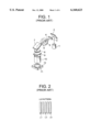
- FIG. 1 is a schematic view illustrating a conventional projection exposing apparatus.
- An excimer laser beam emitted from an excimer laser source 1 is reflected on a mirror 2 to advance into a fly eye lens 4 through a shutter 3 for controlling an exposure.
- the beam whose illumination intensity has been made uniform through this fly eye lens 4 is restricted with a variable opening iris 5, and then passes through a lens system 6.
- the beam is reflected on a mirror 7 and is applied through a condenser lens 8 to a mask 9.
- the beam which has passed through the mask 9 focuses, through a projection lens 10, onto a wafer 11 on a stage 12.
- a resist film on the wafer 11 is exposed to the beam, using a mask wherein a line-and-space pattern (referred to as an LS pattern hereinafter) is formed.
- the LS pattern is composed of plural lines (for example, L1-L5) which have the same width and are arranged in parallel and at even intervals.
- the exposed resist film is developed.
- the widths of the respective lines thereof are measured.
- An aberration (i.e., aberration amount) of a coma can be obtained from the difference between the widths of the lines at both ends of this LS pattern (Japanese Patent Application Laid-Open No. 10-232185).
- the difference between the widths of the both-end lines can be measured in an LS pattern having a line width of, for example, 0.25 ⁇ m by exposure using, as a light source, a KrF excimer laser having a wavelength of 248 nm.
- the difference between the widths of the both-end lines cannot be measured in an LS pattern having a smaller line width, for example, a line width of 0.15 ⁇ um.
- the both-end lines L1 and L5 may become highly thin to fall down by light approaching effect according to exposure using an optimal exposure, wherein the centerline L3 in the LS pattern is resolved to a line width as designed.
- an LS pattern having a width of 0.15 ⁇ m is not resolved by an optimal exposure of the LS pattern.
- the centerline of the LS pattern is exposed to light using the optimal exposure, the both-end lines in the LS pattern are not resolved.
- the difference between widths of right and left lines changes correspondingly to exposures.
- the exposure as a standard be beforehand decided. Since the optimal exposure for the centerline of any LS pattern is not easily affected by aberration, the optical exposure for the centerline of any LS pattern is usually used as the exposure that is the standard.
- An object of the present invention is to provide a method making it possible to measure an aberration of a projection exposing apparatus system from the difference between widths of both-end lines even in a fine pattern having a pattern line width of less than 0.2 ⁇ m.
- a first aspect of the present invention is a method for measuring an aberration of a projection optical system, comprising the steps of:
- a second aspect of the present invention is a method for measuring an aberration of a projection optical system, comprising the steps of:
- a third aspect of the present invention is a method for measuring an aberration of a projection optical system, comprising the steps of:
- a fourth aspect of the present invention is a method for measuring an aberration of a projection optical system, comprising the steps of:
- the inventor has made various researches to obtain the difference between the widths of the both-end lines at the standard exposure in a pattern which has lines having such a very small width that its aberration cannot be measured according to the prior art, for example, less than 0.2 ⁇ m (especially 0.15 ⁇ m).
- this aberration has a correlation with the exposure.
- the difference between the widths of the both-end lines can be obtained at this optimal exposure even in the case that the LS pattern is not resolved at this optimal exposure.
- the aberration of the projection optical system can be obtained from this difference between the widths of the both-end lines.
- the approximation lines are obtained for the exposure fields whose aberrations are to be obtained at the standard exposure.
- the difference between the widths of the both-end lines at the standard exposure can be obtained on the basis of this relationship between the inclination and the both end line width difference. Since the difference between the widths of the both-end lines used to obtain this relationship between the inclination and the both end line width difference is an estimation value of the difference between the widths of the both-end lines at the standard exposure, the resultant difference between the widths of the both-end lines become more accurate.
- FIG. 1 is a schematic view showing a conventional projection exposing apparatus.
- FIG. 2 is a view showing a line-and-space pattern.
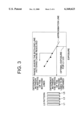
- FIG. 3 is a view for explaining the principle of the present invention.
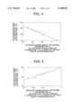
- FIG. 4 is a graph showing the relationship between the optimal exposure at the left end of an exposure field and the difference between the widths of the both-end lines.
- FIG. 5 is a graph showing the relationship between the optimal exposure at the right end of the exposure field and the difference between the widths of the both-end lines.
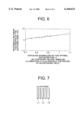
- FIG. 6 is a graph showing the relationship between the optimal exposure at the center of the exposure field and the difference between the widths of the both-end lines.
- FIG. 7 is a schematic view showing an affect on line width of an LS pattern by a coma.
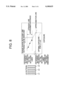
- FIG. 8 is a graph showing the relationship between exposure and the difference between the widths of the both-end lines.
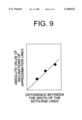
- FIG. 9 is a graph showing the relationship between absolute values of the inclinations of approximation straight lines and estimation values of the differences between the widths of the both-end lines.
- FIG. 3 is a view for explaining the principle of the present invention, and is a graph showing the relationship between exposure, expressed by the horizontal axis of this graph, and difference between widths of both-end lines, expressed by the vertical axis thereof.
- the optimal exposure (standard exposure) for a centerline L3 of an LS pattern is within the range that the both-end lines of the LS pattern are not resolved.
- the relationship between the exposure and the difference between the widths of the both end lines has a correlation similar to linearity.
- FIG. 3 is concerned with a case that the used resist film is a positive type and is exposed to light as a positive pattern. In this case, the both-end lines are not resolved by a high exposure. However, the both-end lines are resolved if the exposure is lowered. On the other hand, in the case that a negative resist film is used and exposed to light as a negative pattern, the inclination of the resultant approximation line is opposite to that of the approximation line shown in FIG. 3. If the exposure is increased, the difference between the widths of the both-end lines is made large.
- the difference between the widths of the both-end lines in any LS pattern is generated by a coma, the difference is used for the quantitative measurement of the coma.
- the difference between the widths of the both-end lines changes by the pitch of a pattern, an illumination condition, the position of the pattern inside an exposure field, and the like. If the both-end lines are not resolved, the difference between the widths of the both-end lines of the LS pattern and coma cannot be obtained.
- the lines of the LS pattern are fine or fall down or in the case that the LS pattern is not separated, it is possible to estimate the difference between the widths of the both-end lines at the optimal exposure for the LS pattern from the following approximation line: in the former case, the approximation line showing the dependency of the difference between the widths of the both-end lines at the side of under-exposure upon exposures; and in the latter case, the approximation line showing the dependency of the difference between the widths of the both-end lines at the side of over-exposure upon exposures.
- the approximation line shown in FIG. 3 is a straight line, but the resultant correlation does not necessarily have linearity.
- the correlation between the exposure and the difference between the widths of the both-end lines has sufficient linearity in the range near the range where the both-end lines can be resolved. Accordingly, even when a subject pattern is very fine and thus the pattern is not resolved on a resist film by a standard exposure so that a resist pattern is not formed, the difference between the widths of the both-end lines is measured at plural exposures in such a manner that the exposures are changed in the range where a resist pattern is formed. In this way, it becomes possible to estimate the difference between the widths of the both-end lines at the standard exposure from the correlation between the exposure and the difference between the widths of the both-end lines and obtain the aberration at the standard exposure.
- FIG. 2 shows the difference between the widths of the both-end lines, measured at the left end in the longitudinal direction of the one-shot area, in this case.
- FIG. 5 shows the difference between the widths of the both-end lines, measured at the right end thereof, in this case.
- FIG. 6 shows the difference between the widths of the both-end lines, measured at the center thereof, in this case.
- FIGS. 4-6 their horizontal axes express exposure normalized by the optimal exposure for the centerline L3 of the LS pattern.
- the difference between the widths of the both-end lines are measured in the range where the normalized exposure is from 0.75 to 0.93.
- the difference between the widths of the both-end lines becomes smaller at the left end of the exposure field when the exposure becomes larger.
- the difference between the widths of the both-end lines becomes larger at the right end of the exposure field when the exposure becomes larger.
- FIG. 6 at the center of the exposure field a change in the difference between the widths of the both-end lines is little against a change in the exposure. However, when the exposure increases, the difference between the widths of the both-end lines slightly increases.
- the relationship between the exposure and the difference between the widths of the both-end lines has a linear correlation.
- the optimal exposure for the line L3 that is, at the point where the exposure normalized in FIGS. 4-6 is 1, the difference between the widths of the both-end lines was not obtained.
- an approximation line is obtained from the measured points in FIGS. 4-6 and then this approximation line is extrapolated up to the point where the normalized exposure is 1 to obtain the difference between the widths of the both-end lines at the point where the normalized exposure is 1, it is possible to obtain comas in respective positions of the exposure field at the optimal exposure for the line L3.
- the affect of a coma which is a main factor of a scattering in dimension within the exposure field, includes the above-mentioned transcription in the state that the widths of the both-end lines of an LS pattern are different.
- FIG. 7 is a schematic view showing the affect of coma on an LS pattern (for example, L1-L5). As shown in FIG. 7, the difference between widths of the both-end lines of the LS pattern transcribed in the state that the line widths are different by the coma has a correlation with exposure, as stated about the first embodiment. The correlation has a sufficient linearity in the range near the range where the both-end lines (L1 and L5 in the case shown in FIG. 7) are resolved.
- the optimal exposure for the centerline in the LS pattern is used as a standard exposure, and the difference between the widths of the both-end lines, at the standard exposure, is used as an index.
- the coma at the standard exposure is obtained from the dependency of exposure upon the difference between the widths of the both-end lines.
- the inclination of the approximation line showing the relationship between the difference between the widths of the both-end lines and the exposure used in the first embodiment. In this way, the difference between the widths of the both-end lines is indirectly obtained.
- FIG. 8 is a graph showing the relationship between exposure and the difference between the widths of both-end lines. Its horizontal axis expresses the exposure, and the vertical axis expresses the difference between the widths of the both-end lines of an LS pattern. As shown in FIG. 8, the relationship of the dependency of the exposure upon the difference between the widths of the both-end lines is caused to approximate a straight line. This straight line is used to obtain the estimation value of the difference between the widths of the both-end lines at the optimal exposure.
- the dependency upon the exposure can substantially approximate a straight line near the target dimension of the both-lines of the pattern, that is, the line width of the mask.
- a method for obtaining an approximation line there is, for example, a method of obtaining the average of the line widths of the both-end lines L1 and L5 resolved at a specific exposure, extracting such data that this average falls within ⁇ 10% of the target dimension of line width, plotting the relationship between exposure and the difference between the widths of the both-end lines about these data, and approximating the resultant to a straight line.
- a mask having a line width of 200 nm, which is a target dimension, is used to change an exposure fron "a" to "g".
- the average of the widths of the lines L1 and L5 of the thus obtained LS pattern is obtained. It is assumed that in the case the following are obtained:
- the line widths L1-L5 are wide, dependency on exposure is strong, and in the case that the line widths L1-L5 are narrow, dependency on exposure is weak. Therefore, in the case that the dependency of the difference between the widths of the both-end lines upon exposure is caused to approximate a straight line, accidental errors become large if an approximation line is obtained using all measured values in the range where the both-end lines L1 and L5 are resolved.
- the range of the exposure for obtaining the approximation line is preferably set in such a manner that the resultant widths of the both-end lines are near the target dimension.
- FIG. 8 is obtained about plural exposure fields.
- Each of the inclinations of the approximation lines showing the dependency of exposure is obtained.
- FIG. 9 is a graph showing the relationship between the absolute values of inclinations of approximation lines and the estimation values of the difference between the widths of the both-end lines at the optimal exposure.
- approximation straight lines as shown in FIG. 8 are obtained for the plural exposure fields and then the relationship between the absolute values of the inclinations of the plural approximation straight lines and estimation values of the difference between the widths of the both-end lines at the standard exposure (that is, the relationship between the inclination and the both end line width difference hereinafter) is beforehand obtained.
- the approximation lines are obtained for the exposure fields whose aberrations are to be obtained at the standard exposure. If their inclinations are applied to the above-mentioned and beforehand-obtained relationship between the inclination and the both end line width difference, the difference between the widths of the both-end lines at the standard exposure can be obtained. Accordingly, aberrations at the optimal exposure can be obtained from the difference between the widths of the both-end lines.
- the approximation straight lines are obtained from the plural exposure-dependencies by changing the exposure fields and measuring the difference between the widths of the both-end lines.
- the inclinations of the approximations straight lines which are obtained from the relationship between the difference between the widths of the both-end lines and exposure, become also different.
- the inclination thereof is larger. This is the following reason. As the subject dimension is finer, an influence is easily produced by lens aberration. As mask dimension becomes smaller so that the value of (L1+L5) becomes smaller, the value of the abnormal line width value defined as (L1-L5)/(L1+L5) changes more sensitively.
- the inclination of the approximation straight line trends to be large. This is because an influence is easily produced by lens aberration under such illumination conditions.
- the line whose width is thicker among the right and left lines L1 and L5 becomes reverse.
- the signs of the abnormal line width value become reverse and further the inclinations of the approximation straight line become reverse.
- the abnormal line width value and the inclination thereof become larger.
- the calculated value of light intensity is reflected as it is on the above-mentioned parameters.
- the fact that the line width grows fat or becomes thin is more emphasized.
- the dependency of the particular pattern upon exposure is bad so that the inclination of the abnormal line width values becomes large.
- Plural approximation straight lines are obtained by changing such conditions as the subject dimension, the illumination conditions ( ⁇ ) or the resist, and then the relationship between the inclination and the both end line width difference is beforehand obtained. Even if the inclinations of the approximation straight lines obtained from the relationship between the difference between the widths of the both-end lines and exposure are different by changing these conditions, they are applied to the beforehand-obtained relationship between the inclination and the both end line width difference so that the difference between the widths of the both-end lines can be obtained at the standard exposure. From this difference between the widths of the both-end lines, the aberration at the standard exposure can be obtained.
- the difference between the widths of the both-end lines and the coma at the optimal exposure can be indirectly obtained from the relationship between the inclination and the both end line width difference.
- the present embodiment is concerned with a case that the resist film is a positive type and is exposed to light as a positive pattern.
- the both-end lines are not resolved at a high exposure.
- the both-end lines are resolved if the exposure is lowered.
- the inclination of such an approximation straight line as shown in FIG. 8 becomes reverse and the difference between the widths of the both-end lines becomes large.
- the relationship between the inclination and the both end line width difference is a proportional relationship. From this proportional relationship, the difference between the widths of the both-end lines and the aberration can be indirectly obtained.
- the difference between the widths of the both-end lines at the standard exposure optimal for the center line of an LS pattern can be obtained even in the case that the pattern has lines having such a very small width that its aberration cannot be measured according to the prior art, for example, less than 0.2 ⁇ m (especially 0.15 ⁇ m).
- aberration can be obtained.
Landscapes
- Physics & Mathematics (AREA)
- General Physics & Mathematics (AREA)
- Exposure And Positioning Against Photoresist Photosensitive Materials (AREA)
- Exposure Of Semiconductors, Excluding Electron Or Ion Beam Exposure (AREA)
- Testing Of Optical Devices Or Fibers (AREA)
Abstract
Description
Claims (13)
Applications Claiming Priority (4)
| Application Number | Priority Date | Filing Date | Title |
|---|---|---|---|
| JP1685699 | 1999-01-26 | ||
| JP11-016856 | 1999-01-26 | ||
| JP11-201982 | 1999-07-15 | ||
| JP20198299A JP3267272B2 (en) | 1999-01-26 | 1999-07-15 | Measurement method of aberration amount of projection optical system |
Publications (1)
| Publication Number | Publication Date |
|---|---|
| US6160623A true US6160623A (en) | 2000-12-12 |
Family
ID=26353294
Family Applications (1)
| Application Number | Title | Priority Date | Filing Date |
|---|---|---|---|
| US09/490,475 Expired - Lifetime US6160623A (en) | 1999-01-26 | 2000-01-24 | Method for measuring an aberration of a projection optical system |
Country Status (4)
| Country | Link |
|---|---|
| US (1) | US6160623A (en) |
| JP (1) | JP3267272B2 (en) |
| KR (1) | KR20000057799A (en) |
| GB (1) | GB2346220B (en) |
Cited By (3)
| Publication number | Priority date | Publication date | Assignee | Title |
|---|---|---|---|---|
| US6538740B1 (en) * | 1998-02-09 | 2003-03-25 | Nikon Corporation | Adjusting method for position detecting apparatus |
| US6825939B2 (en) * | 2001-07-04 | 2004-11-30 | Leica Microsystems Semiconductor Gmbh | Method and measuring arrangement for detecting an object |
| CN109297686A (en) * | 2018-11-16 | 2019-02-01 | 京东方科技集团股份有限公司 | Graphic line width measurement method and system, data processing device |
Families Citing this family (5)
| Publication number | Priority date | Publication date | Assignee | Title |
|---|---|---|---|---|
| KR100682177B1 (en) * | 2000-02-25 | 2007-02-12 | 주식회사 하이닉스반도체 | Lens aberration measurement method of semiconductor exposure equipment |
| KR100714266B1 (en) * | 2001-05-23 | 2007-05-02 | 삼성전자주식회사 | Image correction method in manufacturing process of semiconductor device |
| JP3615181B2 (en) * | 2001-11-06 | 2005-01-26 | 株式会社東芝 | Inspection method for exposure apparatus, exposure method for correcting focus position, and method for manufacturing semiconductor device |
| KR100425479B1 (en) * | 2002-05-02 | 2004-03-30 | 삼성전자주식회사 | Mask for estimating aberration in projection lens system of exposure apparatus |
| CN109612512B (en) * | 2018-10-23 | 2021-11-23 | 南京航空航天大学 | Multi-mode integrated test platform and test method for space-based photoelectric system |
Citations (2)
| Publication number | Priority date | Publication date | Assignee | Title |
|---|---|---|---|---|
| US5208629A (en) * | 1991-04-05 | 1993-05-04 | Nippon Telegraph & Telephone Corporation | Optical projection exposure method and system using the same |
| JPH10232185A (en) * | 1996-12-19 | 1998-09-02 | Nikon Corp | Aberration measurement method of projection optical system |
Family Cites Families (1)
| Publication number | Priority date | Publication date | Assignee | Title |
|---|---|---|---|---|
| TW357262B (en) * | 1996-12-19 | 1999-05-01 | Nikon Corp | Method for the measurement of aberration of optical projection system, a mask and a exposure device for optical project system |
-
1999
- 1999-07-15 JP JP20198299A patent/JP3267272B2/en not_active Expired - Fee Related
-
2000
- 2000-01-24 KR KR1020000003255A patent/KR20000057799A/en not_active Abandoned
- 2000-01-24 US US09/490,475 patent/US6160623A/en not_active Expired - Lifetime
- 2000-01-26 GB GB0001819A patent/GB2346220B/en not_active Expired - Fee Related
Patent Citations (2)
| Publication number | Priority date | Publication date | Assignee | Title |
|---|---|---|---|---|
| US5208629A (en) * | 1991-04-05 | 1993-05-04 | Nippon Telegraph & Telephone Corporation | Optical projection exposure method and system using the same |
| JPH10232185A (en) * | 1996-12-19 | 1998-09-02 | Nikon Corp | Aberration measurement method of projection optical system |
Cited By (4)
| Publication number | Priority date | Publication date | Assignee | Title |
|---|---|---|---|---|
| US6538740B1 (en) * | 1998-02-09 | 2003-03-25 | Nikon Corporation | Adjusting method for position detecting apparatus |
| US6825939B2 (en) * | 2001-07-04 | 2004-11-30 | Leica Microsystems Semiconductor Gmbh | Method and measuring arrangement for detecting an object |
| EP1273877A3 (en) * | 2001-07-04 | 2005-11-09 | Leica Microsystems Semiconductor GmbH | Method and measuring device for the detection of an object |
| CN109297686A (en) * | 2018-11-16 | 2019-02-01 | 京东方科技集团股份有限公司 | Graphic line width measurement method and system, data processing device |
Also Published As
| Publication number | Publication date |
|---|---|
| JP3267272B2 (en) | 2002-03-18 |
| KR20000057799A (en) | 2000-09-25 |
| JP2000283890A (en) | 2000-10-13 |
| GB0001819D0 (en) | 2000-03-22 |
| GB2346220B (en) | 2001-05-23 |
| GB2346220A (en) | 2000-08-02 |
Similar Documents
| Publication | Publication Date | Title |
|---|---|---|
| JP3037887B2 (en) | Lithographic exposure monitoring method and apparatus | |
| KR100714480B1 (en) | systems and methods for detecting focus variation in photolithograph process using test features printed from photomask test pattern images | |
| JP3265668B2 (en) | How to calculate the best focus position | |
| US7879513B2 (en) | Method for correcting mask | |
| JP2854551B2 (en) | Manufacturing method of exposure mask | |
| US6815129B1 (en) | Compensation of flare-induced CD changes EUVL | |
| US7327436B2 (en) | Method for evaluating a local flare, correction method for a mask pattern, manufacturing method for a semiconductor device and a computer program product | |
| JP4057847B2 (en) | Lithographic projection apparatus calibration method, patterning apparatus, and device manufacturing method | |
| KR100988987B1 (en) | Photo mask pair for flare measurement, flare measuring instrument and flare measuring method | |
| US6208469B1 (en) | Method of adjusting reduction projection exposure device | |
| US6764794B2 (en) | Photomask for focus monitoring | |
| US6797443B2 (en) | Focus monitoring method, focus monitoring apparatus, and method of manufacturing semiconductor device | |
| KR100763222B1 (en) | Photomask structures providing improved photolithographic process windows and methods of manufacturing the same | |
| US6160623A (en) | Method for measuring an aberration of a projection optical system | |
| KR100285927B1 (en) | Phase-shifting mask, exposure method and method for measuring amount of spherical aberration | |
| US7368209B2 (en) | Method for evaluating sensitivity of photoresist, method for preparation of photoresist and manufacturing method of semiconductor device | |
| JP4329333B2 (en) | Exposure mask correction method | |
| JPH118194A (en) | Exposure condition measurement method, projection optical system evaluation method, and lithography system | |
| JP2972528B2 (en) | Exposure method | |
| JPH10232185A (en) | Aberration measurement method of projection optical system | |
| JP2008140911A (en) | Focus monitor method | |
| US20020048018A1 (en) | Method for measuring coma aberration in optical system | |
| JP2000292904A (en) | Method and apparatus for measuring phase difference of phase shift mask | |
| JP4137087B2 (en) | Exposure apparatus and device manufacturing method | |
| JP3930401B2 (en) | Method for measuring numerical aperture in fine image projection exposure apparatus |
Legal Events
| Date | Code | Title | Description |
|---|---|---|---|
| AS | Assignment |
Owner name: NEC CORPORATION, JAPAN Free format text: ASSIGNMENT OF ASSIGNORS INTEREST;ASSIGNORS:UCHIYAMA, TAKAYUKI;MATSUURA, SEIJI;REEL/FRAME:010524/0255 Effective date: 20000118 |
|
| STCF | Information on status: patent grant |
Free format text: PATENTED CASE |
|
| FEPP | Fee payment procedure |
Free format text: PAYOR NUMBER ASSIGNED (ORIGINAL EVENT CODE: ASPN); ENTITY STATUS OF PATENT OWNER: LARGE ENTITY |
|
| AS | Assignment |
Owner name: NEC ELECTRONICS CORPORATION, JAPAN Free format text: ASSIGNMENT OF ASSIGNORS INTEREST;ASSIGNOR:NEC CORPORATION;REEL/FRAME:013751/0721 Effective date: 20021101 |
|
| FPAY | Fee payment |
Year of fee payment: 4 |
|
| FPAY | Fee payment |
Year of fee payment: 8 |
|
| AS | Assignment |
Owner name: RENESAS ELECTRONICS CORPORATION, JAPAN Free format text: CHANGE OF NAME;ASSIGNOR:NEC ELECTRONICS CORPORATION;REEL/FRAME:025375/0939 Effective date: 20100401 |
|
| FPAY | Fee payment |
Year of fee payment: 12 |
|
| AS | Assignment |
Owner name: RENESAS ELECTRONICS CORPORATION, JAPAN Free format text: CHANGE OF ADDRESS;ASSIGNOR:RENESAS ELECTRONICS CORPORATION;REEL/FRAME:044928/0001 Effective date: 20150806 |