US6152650A - Wastewater and effluent distribution system - Google Patents
Wastewater and effluent distribution system Download PDFInfo
- Publication number
- US6152650A US6152650A US09/161,332 US16133298A US6152650A US 6152650 A US6152650 A US 6152650A US 16133298 A US16133298 A US 16133298A US 6152650 A US6152650 A US 6152650A
- Authority
- US
- United States
- Prior art keywords
- liquid
- effluent
- distribution box
- distribution
- flow
- Prior art date
- Legal status (The legal status is an assumption and is not a legal conclusion. Google has not performed a legal analysis and makes no representation as to the accuracy of the status listed.)
- Expired - Lifetime
Links
- 239000002351 wastewater Substances 0.000 title abstract description 8
- 239000007788 liquid Substances 0.000 claims abstract description 110
- 238000007689 inspection Methods 0.000 claims description 5
- 238000012544 monitoring process Methods 0.000 claims 2
- 238000010521 absorption reaction Methods 0.000 description 9
- 239000010865 sewage Substances 0.000 description 4
- 210000003813 thumb Anatomy 0.000 description 4
- 239000012530 fluid Substances 0.000 description 1
- 239000000463 material Substances 0.000 description 1
- 238000000034 method Methods 0.000 description 1
- 238000012986 modification Methods 0.000 description 1
- 230000004048 modification Effects 0.000 description 1
- 238000005192 partition Methods 0.000 description 1
- 239000002689 soil Substances 0.000 description 1
- 238000001179 sorption measurement Methods 0.000 description 1
- 230000003068 static effect Effects 0.000 description 1
Images
Classifications
-
- E—FIXED CONSTRUCTIONS
- E03—WATER SUPPLY; SEWERAGE
- E03F—SEWERS; CESSPOOLS
- E03F1/00—Methods, systems, or installations for draining-off sewage or storm water
- E03F1/002—Methods, systems, or installations for draining-off sewage or storm water with disposal into the ground, e.g. via dry wells
-
- E—FIXED CONSTRUCTIONS
- E02—HYDRAULIC ENGINEERING; FOUNDATIONS; SOIL SHIFTING
- E02B—HYDRAULIC ENGINEERING
- E02B13/00—Irrigation ditches, i.e. gravity flow, open channel water distribution systems
Definitions
- This invention relates to an improved distribution system for liquids, wastewater and effluent.
- this invention relates to a liquid distribution system for dividing the flow of wastewater or effluent into reasonably equal quantities for distribution to separate discharge pipes, for example in an absorption field, sandfilter or mound.
- Wastewater and sewage disposal systems are designed to disperse wastewater and/or effluent discharged from a wastewater storage system or septic tank into an absorption field.
- the effluent discharged from a septic tank is conventionally directed first into a standard effluent distribution box.
- the distribution box is intended to divide the flow of effluent into separate, reasonably equal quantities of effluent which then pass through separate discharge pipes for distribution in the absorption field. This division of effluent prevents overloading in a single discharge pipe.
- Unequal discharge of effluent in a single discharge pipe can result in disproportionate effluent loading in one of the discharge pipes which can saturate the soil in one location while other locations receive only minimal effluent.
- distribution boxes have one singular sump, relying exclusively on the inherent characteristics of liquids to seek their own level and divide themselves into separate flows by means of a number of discharge pipes connected to the singular sump.
- Each discharge pipe directs an allocated portion of the effluent into different locations in the absorption field.
- Each of the discharge pipes in the distribution box must be set at exactly the same depth to achieve distribution of equal quantities of effluent into each of the discharge pipes. If the discharge pipes are set at different elevations, effluent entering the distribution box tends to flow out of the discharge pipe which is located at the lowest elevation in the distribution box, even if the difference in elevation among the discharge pipes is minimal.
- U.S. Pat. No. 4,298,470 discloses a sewage septic system which includes a septic tank (14) and a distribution box (20), wherein the piping (26) for the effluent in the distribution box (20) includes a liquid leveling cap (34) containing an effluent opening (40). The level of these openings (40) in the caps (34) can be adjusted to accommodate different effluent levels of the piping within the distribution box (20).
- U.S. Pat. No. 3,497,067 discloses a distribution box (10) used in conjunction with a septic tank absorption field system to control the relative flow of septic tank effluent among separate discharge pipes (18).
- a flow divider, or partition (19) is provided in a lower portion of the distribution box (10).
- This flow divider (19) has an upwardly projecting knife edge (20) designed to divide the flow of effluent entering the distribution box (10) into separate, generally equal quantities, regardless of the level of the discharge pipes (18) in the distribution box (10).
- An improvement on this system is disclosed in U.S. Pat. No. 4,605,501.
- the flow divider (26) is designed with a particular shape which fits within the discharge pipes (14).
- U.S. Pat. No. 5,098,568 An additional improvement on this system is disclosed in U.S. Pat. No. 5,098,568.
- the distribution joint (18) contains two or more distribution lines (16a and 16b) leading to separate adsorption fields.
- a flow divider (24) extends across an outlet line (22) in the throat area where the distribution lines (16a and 16b) join.
- a cylindrical control sleeve or flow director (26) is rotatably mounted inside the effluent line (14) and is used to direct the effluent into the respective distribution line (16a and 16b).
- U.S. Pat. No. 4,838,731 discloses a pivotable tray (26), which is installed within a distribution box (12). The effluent from the septic tank flows into this pivotable tray (26) where it collects until its weight causes the tray (26) to pivot and discharge effluent among various discharge outlet pipes (52).
- U.S. Pat. No. 5,322,387 discloses a complicated distribution system for equalizing the flow of fluid through a sewage disposal system.
- U.S. Pat. Nos. 5,107,892, 5,154,353 and 5,680,989 disclose a cap that is placed on the end of piping present in a distribution box. Each of these caps contains a weir, which is designed to equalize the flow of effluent out of the discharge pipes of the distribution box.
- U.S. Pat. No. 3,956,137 discloses a sewage septic system which contains a plurality of discharge lines (23, 24). The flow of effluent in each of these discharge lines may be controlled by a separate gate valve (26, 27), each of which permits full flow, partial flow or no flow through its respective discharge line.
- the present invention is designed to distribute effluent equally among several discharge pipes and represents a significant improvement over the previous products that have relied on a singular sump and a static rise of liquids along with the inherent characteristic of those liquids to seek their own level.
- the present invention discloses a liquid distribution system, particularly an effluent distribution system enclosed in a distribution box. Effluent from a septic tank flows into the distribution box through an inlet pipe for distribution by a series of outlet pipes into an absorption field.
- the liquid distribution system includes a liquid flow splitting system, containing a plurality of separate liquid outlet flow splitting elements. A series of separate liquid outlet flow channels are formed by these liquid outlet flow splitting elements, each of which encourages the effluent into a separate independent sump and then into a corresponding outlet pipe for final distribution in an absorption field.
- the liquid flow splitting system includes slots for outlet flow stop elements in the outlet flow channels to reduce the number of available liquid outlet flow channels which can be used.
- the liquid distribution system includes a level system to monitor the relative position of the liquid distribution system in the ground and an adjusting system to adjust the relative position of the liquid distribution system in the ground.
- an inspection port is provided in the liquid distribution system so that the relative position of the liquid distribution system can be monitored from above ground.
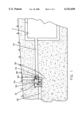
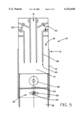
- FIG. 1 is a side view of the liquid distribution system contained in a distribution box connected to a septic tank system in the ground.
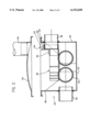
- FIG. 2 is a side view of the liquid distribution system contained in the distribution box.
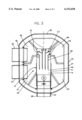
- FIG. 3 is a top view of the liquid distribution system contained in the distribution box.
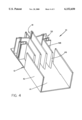
- FIG. 4 is a top perspective view of the liquid distribution system.
- FIG. 5 is a top view of the liquid distribution system.
- the present invention is a liquid distribution system (10) designed to receive small or large quantities of effluent and divide that effluent into a series of relatively equal quantities for distribution among separate outlet pipes (20) in an absorption field.
- the liquid distribution system (10) is designed for utilization with a waste water distribution system, for example, a septic tank (11) as shown in FIG. 1.
- the liquid distribution system (10) including a generally box-like liquid distribution container (12) with a generally flat, bottom surface (14) and side walls (16). It is preferably enclosed within a distribution box (22) having four sides (24, 26, 28, 30), a base (32), a removable top (34), and a number of individual sumps (25) into which the effluent drops from the liquid distribution container (12) as shown in FIGS. 2 and 3.
- This distribution box (22) is located downstream from the septic tank (11) and is buried underground. Effluent enters the distribution box (22) through an inlet pipe (38), as shown in FIG. 1.
- the liquid distribution system (10) includes a series of generally parallel liquid flow splitting elements (48) which extend from the bottom surface (14) of the liquid distribution container (12) to or near the top of the inlet pipe (38) and form individual liquid outlet flow channels (18) as shown in FIGS. 2-5.
- These liquid flow splitting elements (48) are arranged in a generally parallel pattern, perpendicular to the horizontal flow of effluent through the distribution box (22).
- These liquid outlet flow channels (18) are preferably walls that extend through the distribution box (22) from or near the end of the inlet pipe (38) to the separate outlet pipes (20).
- the front edge (49) of each liquid flow splitting element (48) has a sharp edge as shown in FIGS. 3, 4 and 5 for a better division of the effluent.
- liquid flow splitting elements (48) may be included in the liquid distribution system (10). As shown in FIGS. 3 through 5, four liquid flow splitting elements (48) are provided which form five separate liquid outlet flow channels (18) and assist in the division of the effluent to be discharged from the liquid distribution system (10).
- liquid flow splitting elements (48) are preferably made of a high quality plastic material formed by any conventional plastic forming process.
- liquid outlet stops (50) may be incorporated into liquid outlet stop slots (52) in the liquid flow splitting elements (48), as shown in FIG. 5.
- Each liquid outlet stop (50) prevents the flow of effluent out of a single liquid outlet flow channel (18).
- liquid distribution system (10) Even with the improvements provided by the liquid distribution system (10), in order to assure equalization of the flow of the effluent among the respective liquid outlet flow channels (18), it is important that the liquid distribution system (10) be maintained in a level position. Effluent entering the distribution box (22) has a tendency to flow out of the lowest liquid outlet flow channel (18), even with the use of the liquid flow splitting elements (48), and even if the distribution box (22) is only 20 slightly out of level.
- an adjustment system (54) as shown in FIGS. 2, 3 and 5 is incorporated into the liquid distribution system (10) to level the liquid distribution system (10) that is connected to, but independent from, the distribution box (22).
- this adjustment system (54) includes a bubble level (56), which shows the relative position of the liquid distribution system (10).
- the adjustment system (54) also preferably includes a thumb screw (58) with washer (60) and an adjusting lever (62). With a wrench (not shown), preferably a thumb screw wrench on a rod (not shown), the thumb screw (58) is loosened and the lever (62) is moved by the wrench on the rod to level the liquid distribution system (10). After the bubble level (56) is centered, the thumb screw (58) is tightened to secure the liquid distribution system (10) in its level position.
- an inspection port (64) is preferably incorporated into the removable top (34) of the distribution box (22), as shown in FIGS. 1 and 2.
- This inspection port (64) permits viewing of the adjustment system (54) and provides an opening for access to the liquid distribution system (10) by a person on the surface. This person can view the bubble level (56) and make adjustments to the relative position of the liquid distribution system (10) by manipulating the adjusting lever (62) of the adjustment system (54).
- effluent from the septic tank (11) passes down its discharge piping (37) into the inlet pipe (38) for passage through the distribution box (22).
- the effluent then encounters the edges (49) of the liquid flow splitting elements (48).
- the liquid flow splitting elements (48) form the series of liquid outlet flow channels (18).
- the effluent passing through to the distribution box (22) is channeled in a parallel pattern to the horizontal flow of effluent into these separate liquid outlet flow channels (18).
- the effluent is thus divided into generally equal, separate streams of effluent which pass through the liquid outlet flow channels (18) and fall down into separate sumps (25) which feed into the outlet pipes (20) for distribution among the various lines of the absorption fields.
- an adjusting system (54) is incorporated into the liquid distribution system (10) which includes a bubble level (56) to indicate the relative position of the liquid distribution system (10) and an adjusting lever (62) to adjust the relative position of the liquid distribution system (10).
- the amount of effluent can be equalized among the various outlet pipes (20) so that disproportionate loading of any individual outlet pipe (20) is discouraged.
Landscapes
- Engineering & Computer Science (AREA)
- General Engineering & Computer Science (AREA)
- Health & Medical Sciences (AREA)
- Life Sciences & Earth Sciences (AREA)
- Hydrology & Water Resources (AREA)
- Public Health (AREA)
- Water Supply & Treatment (AREA)
- Mechanical Engineering (AREA)
- Civil Engineering (AREA)
- Structural Engineering (AREA)
- Treatment Of Biological Wastes In General (AREA)
Abstract
Description
Claims (13)
Priority Applications (1)
| Application Number | Priority Date | Filing Date | Title |
|---|---|---|---|
| US09/161,332 US6152650A (en) | 1998-09-25 | 1998-09-25 | Wastewater and effluent distribution system |
Applications Claiming Priority (1)
| Application Number | Priority Date | Filing Date | Title |
|---|---|---|---|
| US09/161,332 US6152650A (en) | 1998-09-25 | 1998-09-25 | Wastewater and effluent distribution system |
Publications (1)
| Publication Number | Publication Date |
|---|---|
| US6152650A true US6152650A (en) | 2000-11-28 |
Family
ID=22580760
Family Applications (1)
| Application Number | Title | Priority Date | Filing Date |
|---|---|---|---|
| US09/161,332 Expired - Lifetime US6152650A (en) | 1998-09-25 | 1998-09-25 | Wastewater and effluent distribution system |
Country Status (1)
| Country | Link |
|---|---|
| US (1) | US6152650A (en) |
Cited By (13)
| Publication number | Priority date | Publication date | Assignee | Title |
|---|---|---|---|---|
| US6503392B1 (en) * | 2001-04-02 | 2003-01-07 | Zabel Environmental Technology | Distribution box for a wastewater treatment system |
| WO2004027175A1 (en) | 2002-09-17 | 2004-04-01 | Premier Tech 2000 Ltée | Buoyancy flushing apparatus and method of flushing |
| US20040134542A1 (en) * | 2003-01-14 | 2004-07-15 | Tsigonis Robert C. | System and method for distributing liquid flow into predetermined proportions |
| US20050257845A1 (en) * | 2004-05-24 | 2005-11-24 | Kenneth Burrows | Even-flow septic tee arrangement |
| US20060231086A1 (en) * | 2005-04-19 | 2006-10-19 | Lennox Manufacturing Inc. | Distribution tee assembly |
| US20070053750A1 (en) * | 2003-09-11 | 2007-03-08 | Pipelife Nederland B.V. | Inspection chamber, as well as set of base parts therefor |
| GB2493853A (en) * | 2011-08-19 | 2013-02-20 | Raymond Maccullagh | An effluent flow splitter |
| US20130058723A1 (en) * | 2011-09-07 | 2013-03-07 | Hazard Mitigation, Inc. | Apparatus and Method for Limiting Ice Formation |
| US20140158231A1 (en) * | 2012-12-09 | 2014-06-12 | Christ Spoorenberg | Effluent Flow Splitter |
| USD810857S1 (en) * | 2016-11-16 | 2018-02-20 | Pre-Con Products | Cell for water management system |
| USD810858S1 (en) * | 2016-11-16 | 2018-02-20 | Pre-Con Products | Cell for water management system |
| USD811518S1 (en) * | 2016-11-16 | 2018-02-27 | Pre-Con Products | Cell for water management system |
| WO2018221154A1 (en) * | 2017-05-31 | 2018-12-06 | デンカ株式会社 | Water gate and discharge method for water gate |
Citations (19)
| Publication number | Priority date | Publication date | Assignee | Title |
|---|---|---|---|---|
| US3497067A (en) * | 1967-05-19 | 1970-02-24 | James E Tyson | Distribution means |
| US3956137A (en) * | 1973-12-06 | 1976-05-11 | Langley Hill Quarry | Sewage septic system for a plurality of drain fields |
| US4199274A (en) * | 1978-04-07 | 1980-04-22 | Loth John L | Flow measuring flume of adjustable capacity |
| US4298470A (en) * | 1980-05-22 | 1981-11-03 | Stallings Billy G | Sewage septic system with liquid flow drainage control |
| US4303350A (en) * | 1980-03-20 | 1981-12-01 | Dix Stephen P | Septic leaching system |
| US4464079A (en) * | 1983-07-11 | 1984-08-07 | Chance James M | Irrigation system |
| US4605501A (en) * | 1985-07-12 | 1986-08-12 | Tyson James E | Flow divider for distribution systems |
| US4824614A (en) * | 1987-04-09 | 1989-04-25 | Santa Fe Energy Company | Device for uniformly distributing a two-phase fluid |
| US4838731A (en) * | 1987-09-03 | 1989-06-13 | Norman Gavin | Septic tank distribution box system |
| US4943184A (en) * | 1988-12-09 | 1990-07-24 | The United State Of America As Represented By The Secretary Of Agriculture | Irrigation device |
| US5098568A (en) * | 1989-11-13 | 1992-03-24 | Tyson James E | Septic tank system with controllable distribution means |
| US5099879A (en) * | 1991-05-16 | 1992-03-31 | Coen Company, Inc. | Combustion air flow stabilizer |
| US5107892A (en) * | 1989-10-23 | 1992-04-28 | Plachy Richard F | Weir construction for liquid distributors |
| US5154353A (en) * | 1989-11-16 | 1992-10-13 | Plachy Richard F | Optimized weir construction for liquid distributors |
| US5241867A (en) * | 1987-07-10 | 1993-09-07 | Bertin Et Cie | Method and apparatus for apportioning a primary volume of fluid into a determined number of secondary volumes having a predefined mutual relationship |
| US5322387A (en) * | 1992-06-08 | 1994-06-21 | Heine Robert S | Waste water drainfield |
| US5516232A (en) * | 1994-05-18 | 1996-05-14 | Filipski; Roman F. | Runoff water diverter |
| US5680989A (en) * | 1995-08-14 | 1997-10-28 | Norman F. Gavin | Adjustable weir for liquid distribution systems |
| US5735304A (en) * | 1996-05-14 | 1998-04-07 | Chumley; William M. | Rainwater collection and distribution apparatus and method |
-
1998
- 1998-09-25 US US09/161,332 patent/US6152650A/en not_active Expired - Lifetime
Patent Citations (19)
| Publication number | Priority date | Publication date | Assignee | Title |
|---|---|---|---|---|
| US3497067A (en) * | 1967-05-19 | 1970-02-24 | James E Tyson | Distribution means |
| US3956137A (en) * | 1973-12-06 | 1976-05-11 | Langley Hill Quarry | Sewage septic system for a plurality of drain fields |
| US4199274A (en) * | 1978-04-07 | 1980-04-22 | Loth John L | Flow measuring flume of adjustable capacity |
| US4303350A (en) * | 1980-03-20 | 1981-12-01 | Dix Stephen P | Septic leaching system |
| US4298470A (en) * | 1980-05-22 | 1981-11-03 | Stallings Billy G | Sewage septic system with liquid flow drainage control |
| US4464079A (en) * | 1983-07-11 | 1984-08-07 | Chance James M | Irrigation system |
| US4605501A (en) * | 1985-07-12 | 1986-08-12 | Tyson James E | Flow divider for distribution systems |
| US4824614A (en) * | 1987-04-09 | 1989-04-25 | Santa Fe Energy Company | Device for uniformly distributing a two-phase fluid |
| US5241867A (en) * | 1987-07-10 | 1993-09-07 | Bertin Et Cie | Method and apparatus for apportioning a primary volume of fluid into a determined number of secondary volumes having a predefined mutual relationship |
| US4838731A (en) * | 1987-09-03 | 1989-06-13 | Norman Gavin | Septic tank distribution box system |
| US4943184A (en) * | 1988-12-09 | 1990-07-24 | The United State Of America As Represented By The Secretary Of Agriculture | Irrigation device |
| US5107892A (en) * | 1989-10-23 | 1992-04-28 | Plachy Richard F | Weir construction for liquid distributors |
| US5098568A (en) * | 1989-11-13 | 1992-03-24 | Tyson James E | Septic tank system with controllable distribution means |
| US5154353A (en) * | 1989-11-16 | 1992-10-13 | Plachy Richard F | Optimized weir construction for liquid distributors |
| US5099879A (en) * | 1991-05-16 | 1992-03-31 | Coen Company, Inc. | Combustion air flow stabilizer |
| US5322387A (en) * | 1992-06-08 | 1994-06-21 | Heine Robert S | Waste water drainfield |
| US5516232A (en) * | 1994-05-18 | 1996-05-14 | Filipski; Roman F. | Runoff water diverter |
| US5680989A (en) * | 1995-08-14 | 1997-10-28 | Norman F. Gavin | Adjustable weir for liquid distribution systems |
| US5735304A (en) * | 1996-05-14 | 1998-04-07 | Chumley; William M. | Rainwater collection and distribution apparatus and method |
Cited By (22)
| Publication number | Priority date | Publication date | Assignee | Title |
|---|---|---|---|---|
| US6503392B1 (en) * | 2001-04-02 | 2003-01-07 | Zabel Environmental Technology | Distribution box for a wastewater treatment system |
| WO2004027175A1 (en) | 2002-09-17 | 2004-04-01 | Premier Tech 2000 Ltée | Buoyancy flushing apparatus and method of flushing |
| US20040111794A1 (en) * | 2002-09-17 | 2004-06-17 | Marc-Andre Malenfant | Buoyancy flushing apparatus and method thereof |
| US6886588B2 (en) | 2002-09-17 | 2005-05-03 | Malenfant Marc-Andre | Buoyancy flushing apparatus and method thereof |
| US20040134542A1 (en) * | 2003-01-14 | 2004-07-15 | Tsigonis Robert C. | System and method for distributing liquid flow into predetermined proportions |
| US6997203B2 (en) | 2003-01-14 | 2006-02-14 | Tsigonis Robert C | System and method for distributing liquid flow into predetermined proportions |
| US20070053750A1 (en) * | 2003-09-11 | 2007-03-08 | Pipelife Nederland B.V. | Inspection chamber, as well as set of base parts therefor |
| US7774988B2 (en) * | 2003-09-11 | 2010-08-17 | Pipelife Nederland B.V. | Inspection chamber, as well as set of base parts therefor |
| US20050257845A1 (en) * | 2004-05-24 | 2005-11-24 | Kenneth Burrows | Even-flow septic tee arrangement |
| US7021336B2 (en) * | 2004-05-24 | 2006-04-04 | Kenneth Burrows | Even-flow septic tee arrangement |
| US20060231086A1 (en) * | 2005-04-19 | 2006-10-19 | Lennox Manufacturing Inc. | Distribution tee assembly |
| GB2493853B (en) * | 2011-08-19 | 2013-11-27 | Raymond Maccullagh | An effluent flow splitter |
| GB2493853A (en) * | 2011-08-19 | 2013-02-20 | Raymond Maccullagh | An effluent flow splitter |
| US8920071B2 (en) * | 2011-09-07 | 2014-12-30 | Hazard Mitigation, Inc. | Apparatus and method for limiting ice formation |
| US20130058723A1 (en) * | 2011-09-07 | 2013-03-07 | Hazard Mitigation, Inc. | Apparatus and Method for Limiting Ice Formation |
| US20140158231A1 (en) * | 2012-12-09 | 2014-06-12 | Christ Spoorenberg | Effluent Flow Splitter |
| US9022066B2 (en) * | 2012-12-09 | 2015-05-05 | Christ Spoorenberg | Effluent flow splitter |
| USD810857S1 (en) * | 2016-11-16 | 2018-02-20 | Pre-Con Products | Cell for water management system |
| USD810858S1 (en) * | 2016-11-16 | 2018-02-20 | Pre-Con Products | Cell for water management system |
| USD811518S1 (en) * | 2016-11-16 | 2018-02-27 | Pre-Con Products | Cell for water management system |
| WO2018221154A1 (en) * | 2017-05-31 | 2018-12-06 | デンカ株式会社 | Water gate and discharge method for water gate |
| JPWO2018221154A1 (en) * | 2017-05-31 | 2020-04-02 | デンカ株式会社 | Water lock and water lock drainage method |
Similar Documents
| Publication | Publication Date | Title |
|---|---|---|
| US6152650A (en) | Wastewater and effluent distribution system | |
| US3371033A (en) | Method of treating sewage and apparatus therefor | |
| US5147556A (en) | Thickener | |
| US5480561A (en) | Method and apparatus for treating wastewater | |
| US3819054A (en) | Sewage treatment system | |
| US6503392B1 (en) | Distribution box for a wastewater treatment system | |
| US4175591A (en) | Apparatus for distributing slurries | |
| US10264742B2 (en) | System, particularly for vegetation cultivation, including a water reserve with constant overflow | |
| US4211655A (en) | Upflow filter construction | |
| US4467830A (en) | Conduit for apparatus discharging a liquid | |
| US20020189979A1 (en) | Washing liquid distribution system | |
| US6112766A (en) | Low flow wastewater and effluent distribution system | |
| DE60209782T2 (en) | DEVICE FOR DISTRIBUTING THE USE OF SPECIFIC MINERAL WATER | |
| US3886065A (en) | Waste water treatment plant with balanced load | |
| DE60217014T2 (en) | Apparatus and method for sedimenting fine solid particles from a continuously flowing suspension | |
| US4789487A (en) | Septic tank with integral direct distribution system | |
| US3497067A (en) | Distribution means | |
| US4268156A (en) | Washing apparatus for photographic materials | |
| CA1057130A (en) | Machine for spreading granular or powdered material | |
| US20080164216A1 (en) | Septic tank housing system with extension element | |
| US6772789B1 (en) | Flow leveling device | |
| US5269911A (en) | Waste treatment system | |
| US4726287A (en) | Water washed subfloor system for paint spray booth | |
| US6997203B2 (en) | System and method for distributing liquid flow into predetermined proportions | |
| US10631525B1 (en) | Multi-path aquarium filtration apparatus |
Legal Events
| Date | Code | Title | Description |
|---|---|---|---|
| AS | Assignment |
Owner name: ZOELLER COMPANY, KENTUCKY Free format text: ASSIGNMENT OF ASSIGNORS INTEREST;ASSIGNOR:HEINE, MICHAEL V.;REEL/FRAME:009484/0543 Effective date: 19980918 |
|
| STCF | Information on status: patent grant |
Free format text: PATENTED CASE |
|
| AS | Assignment |
Owner name: ZOELLER PUMP COMPANY, LLC, KENTUCKY Free format text: ASSIGNMENT OF ASSIGNORS INTEREST;ASSIGNOR:ZOELLER COMPANY, INC.;REEL/FRAME:012322/0175 Effective date: 20010828 |
|
| FPAY | Fee payment |
Year of fee payment: 4 |
|
| FPAY | Fee payment |
Year of fee payment: 8 |
|
| FEPP | Fee payment procedure |
Free format text: PAT HOLDER NO LONGER CLAIMS SMALL ENTITY STATUS, ENTITY STATUS SET TO UNDISCOUNTED (ORIGINAL EVENT CODE: STOL); ENTITY STATUS OF PATENT OWNER: LARGE ENTITY |
|
| FPAY | Fee payment |
Year of fee payment: 12 |