US6152339A - Vehicle rooftop carrier apparatus - Google Patents
Vehicle rooftop carrier apparatus Download PDFInfo
- Publication number
- US6152339A US6152339A US09/535,152 US53515200A US6152339A US 6152339 A US6152339 A US 6152339A US 53515200 A US53515200 A US 53515200A US 6152339 A US6152339 A US 6152339A
- Authority
- US
- United States
- Prior art keywords
- assembly
- carrier
- vehicle
- roll bar
- rack
- Prior art date
- Legal status (The legal status is an assumption and is not a legal conclusion. Google has not performed a legal analysis and makes no representation as to the accuracy of the status listed.)
- Expired - Fee Related
Links
- 230000002787 reinforcement Effects 0.000 claims description 5
- 230000000712 assembly Effects 0.000 description 9
- 238000000429 assembly Methods 0.000 description 9
- 239000000463 material Substances 0.000 description 4
- 230000008901 benefit Effects 0.000 description 2
- 239000000969 carrier Substances 0.000 description 2
- 238000010276 construction Methods 0.000 description 2
- 239000004744 fabric Substances 0.000 description 2
- 239000002783 friction material Substances 0.000 description 2
- 230000004048 modification Effects 0.000 description 2
- 238000012986 modification Methods 0.000 description 2
- 241001061260 Emmelichthys struhsakeri Species 0.000 description 1
- 241000283899 Gazella Species 0.000 description 1
- WYTGDNHDOZPMIW-RCBQFDQVSA-N alstonine Natural products C1=CC2=C3C=CC=CC3=NC2=C2N1C[C@H]1[C@H](C)OC=C(C(=O)OC)[C@H]1C2 WYTGDNHDOZPMIW-RCBQFDQVSA-N 0.000 description 1
- 229910052782 aluminium Inorganic materials 0.000 description 1
- XAGFODPZIPBFFR-UHFFFAOYSA-N aluminium Chemical compound [Al] XAGFODPZIPBFFR-UHFFFAOYSA-N 0.000 description 1
- 239000002131 composite material Substances 0.000 description 1
- 230000013011 mating Effects 0.000 description 1
- 229910052751 metal Inorganic materials 0.000 description 1
- 239000002184 metal Substances 0.000 description 1
- 239000004033 plastic Substances 0.000 description 1
- 239000012858 resilient material Substances 0.000 description 1
- 238000007789 sealing Methods 0.000 description 1
Images


Classifications
-
- B—PERFORMING OPERATIONS; TRANSPORTING
- B60—VEHICLES IN GENERAL
- B60R—VEHICLES, VEHICLE FITTINGS, OR VEHICLE PARTS, NOT OTHERWISE PROVIDED FOR
- B60R9/00—Supplementary fittings on vehicle exterior for carrying loads, e.g. luggage, sports gear or the like
Definitions
- This invention relates to a rack carrier for mounting atop a convertible sport utility vehicle (SUV) and the like.
- SUV convertible sport utility vehicle
- Convertible SUV vehicles such as JEEP®, LAND ROVER®, GAZELLE® sports utility vehicles and the like, offer the benefit of rugged performance for off-road use, while at the same time allowing the open-air enjoyment of a removable top.
- the tops can be removable hard tops or flexible tops made, e.g., of fabric, coated canvas, and the like.
- a major disadvantage of such sport utility vehicles is their relative lack of cargo space. Any cargo that is carried must essentially be accommodated within the passenger compartment, which is limited. For situations where large items are desired to be transported, the interior cargo space of many sports utility vehicles is inadequate.
- the male engagement element is associated with the roll bar clamp assembly, preferably with the male engagement element extending generally vertically upward from the upper roll bar clamp element of the roll bar clamp assembly, for releasable engagement extending within the bore of the female sleeve element.
- the female sleeve element is associated with the carrier rail clamp assembly, preferably with the female sleeve element extending generally vertically downward from the lower carrier rail clamp element of the carrier rail clamp assembly, for releasable engagement of the bore over the male engagement element.
- the male engagement element and the female sleeve element define respective transverse apertures in cooperative alignment when the male engagement element extends within the bore of the female sleeve element, and the releasable engagement assembly securing element extends through the transverse apertures in cooperative alignment, releasably securing the male engagement element against dislodgement from within the bore of the female sleeve element.
- the cooperative clamping assembly further comprises disengageable interference structure associated with the releasable engagement assembly securing element for resisting its dislodgement from the transverse apertures in cooperative alignment.
- a vehicle with a roll bar and a vehicle carrier rack assembly removably mounted upon the roll bar comprises the unitary carrier rack and cooperative clamping assembly for releasably mounting the unitary carrier rack upon the vehicle roll bar, as described above.
- the vehicle further comprises at least one grommet assembly for mounting upon the roof of the vehicle around a hole formed therein, and receiving therethrough, in water-tight relationship, a portion of the cooperative, releasable engagement assembly, wherein the roof of the vehicle passes between the roll bar of the vehicle and the unitary carrier rack.
- the unitary carrier rack has sidewalls and a floor; preferably, the sidewalls comprise lower and upper siderail members, reinforcement members between the lower and upper siderail members, and corner posts, and the floor of the unitary carrier rack comprises the lower siderail members, bottom rail members and cross rail members.
- the first and second outer rack hinge elements extend from the front rack support bar and the inner rack hinge element extends from the unitary carrier rack.
- the vehicle carrier rack assembly further comprises the cooperative clamping assembly for releasably mounting the unitary carrier rack upon the vehicle roll bar, as described above.
- the vehicle carrier rack assembly also further comprises at least one grommet assembly for mounting upon the roof of the vehicle around a hole formed therein for receiving therethrough, in water-tight relationship, with the unitary carrier rack in the first position, a portion of the cooperative, releasable engagement assembly, also as described above.
- the vehicle carrier rack assembly further comprises: a ladder mounted at the rear of the vehicle; and at least one ladder hinge assembly comprising: first and second outer ladder hinge elements extending from one of the unitary carrier rack and the ladder, an inner ladder hinge element extending from another of the unitary carrier rack and the ladder and generally between the first and second outer ladder hinge elements, and a hinge pin, the inner ladder hinge element and the first and second outer ladder hinge elements defining respective transverse apertures in cooperative alignment for receiving the hinge pin therethrough, whereby the ladder is pivotable about an axis, defined by the ladder hinge pin, between a first position, with the ladder extending at the rear of the vehicle, with a first, free end disposed for access from the ground, and a second position, with the ladder pivoted away and spaced from the rear of the vehicle.
- the first and second outer ladder hinge elements extend from the unitary carrier rack and the inner ladder hinge element extends from the ladder.
- the ladder has a second, upper end, opposite the first end, with the ladder in the first position, the second end being disposed for access to the unitary carrier rack.
- the invention thus provides a vehicle carrier rack assembly that can be removably mounted on a vehicle having a roll bar by means of releasable clamp assemblies, the rack consisting of a unitary rack member, e.g., having sidewalls and a floor, the clamp assemblies mounting the vehicle carrier rack to the vehicle roll bar.
- the vehicle rack assembly further has grommet assemblies mounted about holes formed in the vehicle roof for passing the clamp assemblies therethrough, the vehicle roof being positioned between the roll bar and the vehicle rack assembly.
- the rack may be mounted to the vehicle by hinges, e.g., to allow the rack to be pivoted between a travel position and a raised position to facilitate removal and replacement of the vehicle roof.
- a ladder may also be attached to the rack at the rear of the vehicle, e.g. for ease of access to the rack on the vehicle roof.
- the ladder may be attached to the rack by hinges, permitting it to be moved away from the rear of the vehicle, e.g. for access to the rear passenger compartment, or to facilitate removing or replacing the vehicle roof.
- Features of the invention may also include a unitary, welded rack providing greater strength and eliminate the rattle of loosened bolts.
- the vehicle rack assembly is also easily placed on and removed from the vehicle, and it does not interfere with convenient removal and replacement of the convertible top of a sport utility vehicle.
- the rack is also attractive and does not require any aesthetically undesirable supports to remain on the vehicle when the rack is not attached.
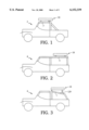
- FIG. 1 is a somewhat diagrammatic side view of a sports utility vehicle (“SUV”) equipped with a vehicle carrier rack according to the invention
- FIG. 2 is a similar diagrammatic side view of another type of sports utility vehicle equipped with a vehicle carrier rack of the invention.
- FIG. 3 is a similar diagrammatic side view of still another type of sports utility vehicle equipped with a vehicle carrier rack of the invention.
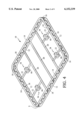
- FIG. 4 is a perspective view of a vehicle carrier rack of the invention.
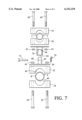
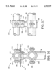
- FIGS. 5 and 6 are face plan and side plan views, respectively, of a cooperative clamping assembly of the invention, for releasably mounting a carrier rack upon a vehicle roll bar;
- FIG. 7 is an exploded view of the cooperative clamping assembly of FIGS. 5 and 6.
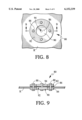
- FIGS. 8 and 9 are top plan and side section views, respectively, of a grommet assembly of the invention, for mounting upon the roof of the vehicle around a hole formed therein for receiving therethrough, in water-tight relationship, a portion of the vehicle carrier rack.
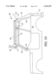
- FIG. 10 is a somewhat diagrammatic side view of a sports utility vehicle equipped with a vehicle carrier rack pivotably-mounted thereto, and a ladder pivotably-mounted to the rack, according to other embodiments of the invention.
- FIG. 11 is a somewhat diagrammatic top perspective view of the vehicle carrier rack assembly of FIG. 10;
- FIG. 12 is face plan view of a hinge element of a hinge assembly of the invention.
- FIG. 13 is a face plan view of a hinge assembly of the invention.
- FIGS. 14 and 15 are side section and side plan views, respectively, of the hinge assembly.
- FIGS. 16 and 17 are face plan and side plan views, respectively, of another embodiment of a cooperative clamping assembly of the invention.
- FIG. 1 depicts a vehicle carrier rack 10 on a sports utility vehicle 2 having a forward, over-cab roll bar 3, e.g., as found on JEEP® CJTM model sports utility vehicles
- FIG. 2 depicts the vehicle carrier rack 10 mounted on a sports utility vehicle 4 having parallel horizontal rear roll bar members 5, e.g., as found on 1997 model year and later JEEP® WRANGLERTM models
- FIG. 3 depicts the vehicle carrier rack 10 mounted on a sports utility vehicle 6 having rear roll bar members 7 disposed at an angle to the horizontal, e.g., as found on JEEP® WRANGLERTM models made prior to the 1997 model year.
- a vehicle carrier rack 10 includes a lower siderail member 12 and an upper siderail member 14, each extending about the entire perimeter of the rack 10.
- the upper siderail member 14 is mounted atop corner posts 16.
- Bottom rail members 20 span between opposite segments of the lower siderail member 12, and bottom crossrail members 22 span between the outermost bottom rail members 20 and adjacent, opposite segments of the lower siderail 12.
- Crossrail members 22 may also be provided between the bottom rail members 20.
- Carrier rail clamp assemblies 34 of cooperative clamping assemblies 30 for releasably mounting the vehicle carrier rack 10 upon a vehicle roll bar, as shown in FIGS.
- 1-3 and described more fully below, are positioned on the crossrail members 22, e.g., as depicted in FIG. 4, or, alternatively, on the lower siderail member 12 or the bottom rail members 20, the locations being selected, e.g., as necessary to accommodate the particular types of vehicle upon which the vehicle carrier rack 10 is to be mounted.
- the vehicle carrier rack 10 is formed of 11/2 inch diameter tubular metal stock, e.g. aluminum.
- the overall construction is preferably welded for strength.
- the vehicle carrier rack 10 may be formed, e.g., of suitable high-impact plastic, e.g., molded in part or in its entirety, or other suitable material. Composite materials, such as those known in the art, may also be used.
- a cooperative clamping assembly 30 of the invention for releasably mounting a carrier rack 10 upon a vehicle roll bar includes a roll bar clamp assembly 32, a carrier rail clamp assembly 34, and a cooperative, releasable engagement assembly 36.
- the roll bar clamp assembly 32 includes a lower roll bar clamp element 38 defining a lower bar clamping surface 40 for engagement with a roll bar surface, S (FIG. 7), an upper roll bar clamp element 42 defining an upper bar clamping surface 44 for engagement with a roll bar surface, S, and roll bar clamp assembly securement elements 46, e.g.
- the carrier rail clamp assembly 34 includes a lower carrier rail clamp element 50 defining a lower rail clamping surface 52 for engagement with a carrier rail surface, T (FIG. 7), an upper carrier rail clamp element 54 defining an upper rail clamping surface 56 for engagement with a carrier rail surface, T, and carrier rail clamp assembly securement elements 58, e.g.
- the cooperative, releasable engagement assembly 36 includes a male engagement element 62 extending generally vertically upward from the upper roll bar clamp element 42 of the roll bar clamp assembly 32, for releasable engagement extending within a bore 64 of a female sleeve element 66 sized and configured for cooperatively receiving the male engagement element 62 extending therewithin.
- the female sleeve element 66 extends generally vertically downward from the lower carrier rail clamp element 50 of the carrier rail clamp assembly 34, for releasable engagement of the bore 64 over the male engagement element 62.
- the male engagement element 62 and the female sleeve element 66 define respective transverse apertures 68, 70 in cooperative alignment (with male engagement element 62 extended within the bore 64 of the female sleeve element 66), and a releasable engagement assembly securing element, e.g. pin 72, extends through the transverse apertures 68, 70 in cooperative alignment, releasably securing the male engagement element 62 against dislodgement from within the bore 64 of the female sleeve element 66.
- a disengageable interference structure e.g., cotter pin 74, is associated with the releasable engagement assembly securing element 72 for resisting its dislodgement from the transverse apertures 68, 70 in cooperative alignment.
- a roof grommet assembly 80 is provided for allowing the female sleeve element 66, or, in the preferred embodiment, allowing the male engagement element 62, of the cooperative clamping assembly 30 to pass through the roof, R, of the vehicle.
- the grommet assembly 80 is depicted in FIGS. 8 and 9 in greater detail.
- the roof, R, of the vehicle may be either a soft fabric top, or a hard top, such are known in the sports utility vehicle market.
- a pair of annular plates 82, 84 are positioned at opposite surfaces of the roof, R, with a seal disk 86 of suitable resilient material, e.g. rubber, between the outer annular plate 82 and the outside surface of the vehicle roof, R.
- annular plates 82, 84 are then secured together, with the seal disk 86 and roof material therebetween, by attachment members 88, which are preferably rivets, but can be bolts or other attachment members known in the art.
- attachment members 88 which are preferably rivets, but can be bolts or other attachment members known in the art.
- the hole 90 at the center of the annular plates 82, 84 corresponds to a hole 92 formed for the purpose in the roof, R, of the vehicle, and to a small, resiliently expandable hole 94 in the center of the seal disk 86. As shown in FIG.
- the male engagement element 62 of the cooperative clamping assembly 30 is received through the aligned holes 90, 92, 94 of the annular plates, 82, 84, the vehicle roof, R, and the seal disk 86, respectively, with the hole 94 in the seal disk 86 expanding resiliently to allow the male engagement element 62 to pass therethrough, the material of the seal disk 86 about the hole 94 engaging the outer surface 63 of the male engagement element 62 in water-tight relationship.
- the male engagement element 62 is sized such that the riding height of the grommet assembly 80 allows for adequate access to the releasable engagement assembly securing element (pin 72) from outside the vehicle.
- the grommet assembly 80 is depicted as accommodating the male engagement element 62, such that when the vehicle carrier rack 10 is removed (by removing the releasable engagement assembly securing element (pin 72)) and lifting the rack 10 and the carrier rail clamp assembly 34, with the female sleeve element 66 attached thereto, the upwardly- extending male engagement element 62 remains engaged within the hole 94 in the sealing disk 86, extending above the surface of the vehicle roof, R, with the material of the seal disk 86 about the hole 94 remaining engaged with the outer surface 63 of the male engagement element 62 in water-tight relationship.
- the upwardly extending male engagement element 152 is sized to end only within the vehicle, i.e., below the roof, R.
- the grommet assembly hole 94 may be suitably plugged in known fashion, e.g. with the plug advantageously secured to the male engagement element.
- a vehicle carrier rack assembly 100 for removably mounting upon a vehicle 102 having a roll bar 104 consists of a unitary carrier rack 106, e.g. as described above, a front rack support bar 108 adapted for mounting to windshield brackets 109 of the vehicle, and a pair of carriage rack hinge assemblies 110, 110'.
- each carriage rack hinge assembly 110 is formed of hinge elements 112 (FIG.
- first and second outer hinge elements 114, 116 extending from the front rack support bar 106, with an inner hinge element 118 extending from the unitary carrier rack 106 and generally between first and second outer hinge elements 114, 116, and a hinge pin 120.
- the inner hinge element 118 and the first and second outer hinge elements 114, 116 define respective transverse apertures 115, 117, 119 in cooperative alignment for receiving the hinge pin 120 therethrough.
- the unitary carrier rack 106 is pivotable about an axis, P, defined by the hinge pin 120, between a first position (shown is solid line in FIG. 10), with the unitary carrier rack 106 disposed adjacent the vehicle roof, and a second position (suggested in dashed line in FIG. 10), with the unitary carrier rack 106 pivoted away and spaced from the area 122 of the vehicle roof.
- the vehicle carrier rack assembly includes a cooperative clamping assembly 124, as described above with respect to FIGS. 4-9, with the vehicle carrier rack 106 being constructed and removably mounted to the vehicle roll bar 104.
- the vehicle carrier rack assembly 100 includes a grommet assembly for mounting upon the roof of the vehicle around a hole formed therein for receiving therethrough, in water-tight relationship, a portion of each cooperative, releasable engagement assembly, again, as described above with reference to FIGS. 5, 6, 8 and 9.
- the vehicle carrier rack assembly 100 may further include a ladder 126 mounted at the rear of the vehicle 102, with its upper end 125 disposed for access to the unitary carrier rack 106.
- the ladder 126 is preferably mounted by a pair of ladder hinge assemblies 128 consisting, as described above with respect FIGS. 12-14, of first and second outer hinge elements 114, 116, an inner hinge element 118, generally between the first and second outer hinge elements, and a hinge pin 120.
- the inner hinge element 118, extending from the unitary carrier rack 106, and the first and second outer hinge elements 114, 116, extending from the ladder 126 define respective transverse apertures in cooperative alignment for receiving the hinge pin therethrough.
- the ladder is pivotable about an axis, P, defined by the hinge pin 120, between a first position (shown in solid line in FIG. 10), with the ladder 126 extending at the rear of the vehicle 120, with its free end 127 disposed for access from the ground, and a second position (suggested in dashed line in FIG. 10), with the ladder 126 pivoted away and spaced from the rear of the vehicle 102.
- a cooperative clamping assembly for mounting a vehicle carrier rack 10 upon a vehicle 6 having rear roll bar members 7 disposed at an angle to the horizontal, a cooperative clamping assembly can be provided with the male engagement element 130 formed at an angle to the roll bar clamp assembly.
- Other vehicle configurations can also be accommodated, e.g., with similar or other modifications.
- reinforcement members 18 are also envisioned, e.g. a lattice or a series of plates or posts may be employed.
- two bottom crossrail members 22 are depicted in FIG. 4, any number may be employed, depending, e.g., on the projected cargo weight and resulting strength required, and also dimensions of length and width of vehicle carrier rack the span of the resulting grid.
- the elements of the vehicle carrier rack are depicted as rounded or tubular members, other cross sectional shapes may also be employed.
- a cooperative clamping assembly 130 for releasably mounting a carrier rack upon a vehicle roll bar is shown.
- Carrier rail clamp assembly 132 is engaged about carrier rail, C (i.e., one of a crossrail member 22, a lower siderail member 12, or a bottom rail member 20) as appropriate for the type of vehicle upon which the associated vehicle carrier rack is mounted.
- Upper rack clamp member 134 and lower rack clamp member 136 are mutually sized and configured to securely clamp about the carrier rail, C, therebetween, held by attachment members 138, e.g., carriage or hex bolts, through holes in flanges 140 provided for that purpose.
- one or both of the clamp members 134, 136 may be grooved, scored, or fabricated with gripping teeth or ridges to aid in gripping the carrier rail, C.
- rubber or other high-friction material may be placed at the interfaces between the clamp members 134, 136 and the carrier rail, C.
- the upper roll bar clamp member 142 and lower roll bar clamp 144 are mutually sized and configured to be secured about the roll bar, B, held together by attachment members 146, e.g., carriage or hex bolts, through holes in flanges 148 provided for that purpose.
- attachment members 146 e.g., carriage or hex bolts
- flanges 148 provided for that purpose.
- one or both of the clamp members 142, 144 may be grooved, scored, or fabricated with gripping teeth or ridges, as above, to aid in gripping the roll bar, B.
- rubber or other high-friction material may be placed in the interfaces between the clamp members 142, 144 and the roll bar, B.
- the lower rack clamp member 136 is associated with a downward tubular extension 150 engaged in mating, telescopic engagement with an upward cylindrical extension 152 associated with the upper roll bar clamp member 142.
- the inside diameter of the downward tubular extension 150 is about 11/2 inch, which is approximately the same as the outer diameter of the upward cylindrical extension 152.
- a pin 154 e.g., a carriage bolt, hex bolt, or the like, is placed through aligned cooperating apertures in the extensions 152, 154 to hold the extensions 152, 154 together.
- the orientation of the hinge assemblies 110 between the front rack support bar 108 and the unitary carrier rack 106 and/or between the ladder 126 and the unitary carrier 106 may be reversed, i.e., with the first and second outer hinge elements 114, 116 extending from the unitary carrier 106 and the inner hinge element 118 extending from the front rack support bar 108 and/or from the ladder 126.
Landscapes
- Engineering & Computer Science (AREA)
- Mechanical Engineering (AREA)
- Fittings On The Vehicle Exterior For Carrying Loads, And Devices For Holding Or Mounting Articles (AREA)
Abstract
A vehicle carrier rack assembly for mounting upon the roof of the vehicle includes a cooperative clamping assembly for releasably mounting the carrier rack upon a vehicle roll bar. The rack assembly may further include at least one grommet assembly mounted at a hole formed in the vehicle roof and passing therethrough, in water-tight relationship, a portion of the cooperative, releasable engagement assembly for the vehicle rack. In other embodiments, the rack is hinged to pivot between a first position adjacent the vehicle roof and a second position spaced therefrom, e.g., to facilitate removal and replacement of the vehicle roof. A ladder may be mounted to the carrier rack at the rear of the vehicle to similar purpose.
Description
This application is a continuation-in-part of U.S. Application Ser. No. 09/136,282, filed Aug. 20, 1998, and now allowed.
This invention relates to a rack carrier for mounting atop a convertible sport utility vehicle (SUV) and the like.
Convertible SUV vehicles, such as JEEP®, LAND ROVER®, GAZELLE® sports utility vehicles and the like, offer the benefit of rugged performance for off-road use, while at the same time allowing the open-air enjoyment of a removable top. The tops can be removable hard tops or flexible tops made, e.g., of fabric, coated canvas, and the like.
A major disadvantage of such sport utility vehicles is their relative lack of cargo space. Any cargo that is carried must essentially be accommodated within the passenger compartment, which is limited. For situations where large items are desired to be transported, the interior cargo space of many sports utility vehicles is inadequate.
The prior art teaches various vehicle rooftop carrier apparatus, but offers few solutions for convertible sports utility vehicles. This is because most vehicle rooftop carriers rely upon the rain gutters for mounting, or rely upon the roof of a hardtop vehicle for support. Since convertible sports utility vehicles lack these features, most prior art rooftop carriers are not suitable for use with these types of vehicles. Prior art racks for convertible sports utility vehicles are described, e.g., in Welter U.S. Pat. No. 4,538,752 and by Steel Horse Automotive.
According to one aspect of the invention, a cooperative clamping assembly for releasably mounting a carrier rack upon a vehicle roll bar comprises: a roll bar clamp assembly comprising: a lower roll bar clamp element defining a lower bar clamping surface for engagement with a roll bar surface, an upper roll bar clamp element defining an upper bar clamping surface for engagement with a roll bar surface, and at least one roll bar clamp assembly securement element securing together the lower roll bar clamp and the upper roll bar clamp, with the roll bar engaged generally within and between opposed the lower bar clamping surface and the upper bar clamping surface; a carrier rail clamp assembly comprising: a lower carrier rail clamp element defining a lower rail clamping surface for engagement with a carrier rail surface, an upper carrier rail clamp element defining an upper rail clamping surface for engagement with a carrier rail surface, and at least one carrier rail clamp assembly securement element securing together the lower carrier rail clamp and the upper carrier rail clamp, with the carrier rail engaged generally within and between opposed the lower rail clamping surface and the upper rail clamping surface; and a cooperative, releasable engagement assembly comprising: a male engagement element associated with one of the roll bar clamp assembly and the carrier rail clamp assembly, a female sleeve element defining a bore for cooperatively receiving the male engagement element extending therewithin and associated with another of the roll bar clamp assembly and the carrier rail clamp assembly, and at least one releasable engagement assembly securing element releasably securing the male engagement element in engagement within the bore of the female sleeve element.
Preferred embodiments of this aspect of the invention may include one or more of the following additional features. The male engagement element is associated with the roll bar clamp assembly, preferably with the male engagement element extending generally vertically upward from the upper roll bar clamp element of the roll bar clamp assembly, for releasable engagement extending within the bore of the female sleeve element. The female sleeve element is associated with the carrier rail clamp assembly, preferably with the female sleeve element extending generally vertically downward from the lower carrier rail clamp element of the carrier rail clamp assembly, for releasable engagement of the bore over the male engagement element. The male engagement element and the female sleeve element define respective transverse apertures in cooperative alignment when the male engagement element extends within the bore of the female sleeve element, and the releasable engagement assembly securing element extends through the transverse apertures in cooperative alignment, releasably securing the male engagement element against dislodgement from within the bore of the female sleeve element. Preferably, the cooperative clamping assembly further comprises disengageable interference structure associated with the releasable engagement assembly securing element for resisting its dislodgement from the transverse apertures in cooperative alignment.
According to another aspect of the invention, a vehicle carrier rack assembly for removably mounting upon a vehicle having a roll bar comprises the unitary carrier rack and cooperative clamping assembly for releasably mounting the unitary carrier rack upon the vehicle roll bar, as described above.
According to yet another aspect of the invention, a vehicle with a roll bar and a vehicle carrier rack assembly removably mounted upon the roll bar comprises the unitary carrier rack and cooperative clamping assembly for releasably mounting the unitary carrier rack upon the vehicle roll bar, as described above.
Preferred embodiments of both of the immediately preceding aspects of the invention may include one or more of the following additional features. The vehicle further comprises at least one grommet assembly for mounting upon the roof of the vehicle around a hole formed therein, and receiving therethrough, in water-tight relationship, a portion of the cooperative, releasable engagement assembly, wherein the roof of the vehicle passes between the roll bar of the vehicle and the unitary carrier rack. The unitary carrier rack has sidewalls and a floor; preferably, the sidewalls comprise lower and upper siderail members, reinforcement members between the lower and upper siderail members, and corner posts, and the floor of the unitary carrier rack comprises the lower siderail members, bottom rail members and cross rail members.
According to still another aspect of the invention, a vehicle carrier rack assembly for removably mounting upon a vehicle having a roll bar comprises: a unitary carrier rack; a front rack support bar adapted for mounting to windshield brackets of the vehicle; and at least one carrier rack hinge assembly comprising: first and second outer rack hinge elements extending from one of the front rack support bar and the unitary carrier rack, an inner rack hinge element extending from another of the front rack support bar and the unitary carrier rack and generally between the first and second outer rack hinge elements, and a hinge pin, the inner rack hinge element and the first and second outer rack hinge elements defining respective transverse apertures in cooperative alignment for receiving the hinge pin therethrough, whereby the unitary carrier rack is pivotable about an axis, defined by the hinge pin, between a first position, with the unitary carrier rack disposed adjacent the vehicle roof, and a second position, with the unitary carrier rack pivoted away and spaced from the vehicle roof.
Preferred embodiments of this aspect of the invention may include one or more of the following additional features. The first and second outer rack hinge elements extend from the front rack support bar and the inner rack hinge element extends from the unitary carrier rack. The vehicle carrier rack assembly further comprises the cooperative clamping assembly for releasably mounting the unitary carrier rack upon the vehicle roll bar, as described above. Preferably, the vehicle carrier rack assembly also further comprises at least one grommet assembly for mounting upon the roof of the vehicle around a hole formed therein for receiving therethrough, in water-tight relationship, with the unitary carrier rack in the first position, a portion of the cooperative, releasable engagement assembly, also as described above. The vehicle carrier rack assembly further comprises: a ladder mounted at the rear of the vehicle; and at least one ladder hinge assembly comprising: first and second outer ladder hinge elements extending from one of the unitary carrier rack and the ladder, an inner ladder hinge element extending from another of the unitary carrier rack and the ladder and generally between the first and second outer ladder hinge elements, and a hinge pin, the inner ladder hinge element and the first and second outer ladder hinge elements defining respective transverse apertures in cooperative alignment for receiving the hinge pin therethrough, whereby the ladder is pivotable about an axis, defined by the ladder hinge pin, between a first position, with the ladder extending at the rear of the vehicle, with a first, free end disposed for access from the ground, and a second position, with the ladder pivoted away and spaced from the rear of the vehicle. The first and second outer ladder hinge elements extend from the unitary carrier rack and the inner ladder hinge element extends from the ladder. The ladder has a second, upper end, opposite the first end, with the ladder in the first position, the second end being disposed for access to the unitary carrier rack.
The invention thus provides a vehicle carrier rack assembly that can be removably mounted on a vehicle having a roll bar by means of releasable clamp assemblies, the rack consisting of a unitary rack member, e.g., having sidewalls and a floor, the clamp assemblies mounting the vehicle carrier rack to the vehicle roll bar. For use with a convertible sports utility vehicle having a roof, the vehicle rack assembly further has grommet assemblies mounted about holes formed in the vehicle roof for passing the clamp assemblies therethrough, the vehicle roof being positioned between the roll bar and the vehicle rack assembly. The rack may be mounted to the vehicle by hinges, e.g., to allow the rack to be pivoted between a travel position and a raised position to facilitate removal and replacement of the vehicle roof. A ladder may also be attached to the rack at the rear of the vehicle, e.g. for ease of access to the rack on the vehicle roof. The ladder may be attached to the rack by hinges, permitting it to be moved away from the rear of the vehicle, e.g. for access to the rear passenger compartment, or to facilitate removing or replacing the vehicle roof. Features of the invention may also include a unitary, welded rack providing greater strength and eliminate the rattle of loosened bolts.
The vehicle rack assembly is also easily placed on and removed from the vehicle, and it does not interfere with convenient removal and replacement of the convertible top of a sport utility vehicle. The rack is also attractive and does not require any aesthetically undesirable supports to remain on the vehicle when the rack is not attached.
The details of one or more embodiments of the invention are set forth in the accompanying drawings and the description below. Other features, objects, and advantages of the invention will be apparent from the description and drawings, and from the claims.
FIG. 1 is a somewhat diagrammatic side view of a sports utility vehicle ("SUV") equipped with a vehicle carrier rack according to the invention;
FIG. 2 is a similar diagrammatic side view of another type of sports utility vehicle equipped with a vehicle carrier rack of the invention; and
FIG. 3 is a similar diagrammatic side view of still another type of sports utility vehicle equipped with a vehicle carrier rack of the invention.
FIG. 4 is a perspective view of a vehicle carrier rack of the invention.
FIGS. 5 and 6 are face plan and side plan views, respectively, of a cooperative clamping assembly of the invention, for releasably mounting a carrier rack upon a vehicle roll bar; and
FIG. 7 is an exploded view of the cooperative clamping assembly of FIGS. 5 and 6.
FIGS. 8 and 9 are top plan and side section views, respectively, of a grommet assembly of the invention, for mounting upon the roof of the vehicle around a hole formed therein for receiving therethrough, in water-tight relationship, a portion of the vehicle carrier rack.
FIG. 10 is a somewhat diagrammatic side view of a sports utility vehicle equipped with a vehicle carrier rack pivotably-mounted thereto, and a ladder pivotably-mounted to the rack, according to other embodiments of the invention;
FIG. 11 is a somewhat diagrammatic top perspective view of the vehicle carrier rack assembly of FIG. 10;
FIG. 12 is face plan view of a hinge element of a hinge assembly of the invention;
FIG. 13 is a face plan view of a hinge assembly of the invention; and
FIGS. 14 and 15 are side section and side plan views, respectively, of the hinge assembly.
FIGS. 16 and 17 are face plan and side plan views, respectively, of another embodiment of a cooperative clamping assembly of the invention.
Like reference symbols in the various drawings indicate like elements.
Referring to FIGS. 1, 2 and 3, a vehicle carrier rack 10 of the invention is shown removably mounted upon the roll bar of each of several different configurations of sports utility vehicles. In particular, FIG. 1 depicts a vehicle carrier rack 10 on a sports utility vehicle 2 having a forward, over-cab roll bar 3, e.g., as found on JEEP® CJ™ model sports utility vehicles; FIG. 2 depicts the vehicle carrier rack 10 mounted on a sports utility vehicle 4 having parallel horizontal rear roll bar members 5, e.g., as found on 1997 model year and later JEEP® WRANGLER™ models; and FIG. 3 depicts the vehicle carrier rack 10 mounted on a sports utility vehicle 6 having rear roll bar members 7 disposed at an angle to the horizontal, e.g., as found on JEEP® WRANGLER™ models made prior to the 1997 model year.
Referring now to FIG. 4, a vehicle carrier rack 10 includes a lower siderail member 12 and an upper siderail member 14, each extending about the entire perimeter of the rack 10. The upper siderail member 14 is mounted atop corner posts 16. Reinforcement members 18, shown, by way of example, as continuous serpentine elements on each side, support the construction. Bottom rail members 20 span between opposite segments of the lower siderail member 12, and bottom crossrail members 22 span between the outermost bottom rail members 20 and adjacent, opposite segments of the lower siderail 12. Crossrail members 22 may also be provided between the bottom rail members 20. Carrier rail clamp assemblies 34 of cooperative clamping assemblies 30 for releasably mounting the vehicle carrier rack 10 upon a vehicle roll bar, as shown in FIGS. 1-3 and described more fully below, are positioned on the crossrail members 22, e.g., as depicted in FIG. 4, or, alternatively, on the lower siderail member 12 or the bottom rail members 20, the locations being selected, e.g., as necessary to accommodate the particular types of vehicle upon which the vehicle carrier rack 10 is to be mounted.
In one preferred embodiment, the vehicle carrier rack 10 is formed of 11/2 inch diameter tubular metal stock, e.g. aluminum. The overall construction is preferably welded for strength. Alternatively, the vehicle carrier rack 10 may be formed, e.g., of suitable high-impact plastic, e.g., molded in part or in its entirety, or other suitable material. Composite materials, such as those known in the art, may also be used.
Referring now to FIGS. 5, 6 and 7, a cooperative clamping assembly 30 of the invention for releasably mounting a carrier rack 10 upon a vehicle roll bar includes a roll bar clamp assembly 32, a carrier rail clamp assembly 34, and a cooperative, releasable engagement assembly 36. The roll bar clamp assembly 32 includes a lower roll bar clamp element 38 defining a lower bar clamping surface 40 for engagement with a roll bar surface, S (FIG. 7), an upper roll bar clamp element 42 defining an upper bar clamping surface 44 for engagement with a roll bar surface, S, and roll bar clamp assembly securement elements 46, e.g. bolts 48 and nuts 49, engaged in apertures provided for the purpose, securing together the lower roll bar clamp 38 and the upper roll bar clamp 42, with the vehicle roll bar, B, engaged generally within and between opposed the lower bar clamping surface 40 and the upper bar clamping surface 44. The carrier rail clamp assembly 34 includes a lower carrier rail clamp element 50 defining a lower rail clamping surface 52 for engagement with a carrier rail surface, T (FIG. 7), an upper carrier rail clamp element 54 defining an upper rail clamping surface 56 for engagement with a carrier rail surface, T, and carrier rail clamp assembly securement elements 58, e.g. bolts 60 and nuts 61, engaged in apertures provided for the purpose, securing together the lower carrier rail clamp 50 and the upper carrier rail clamp 54, with the carrier rail, C, engaged generally within and between opposed the lower rail clamping surface 52 and the upper rail clamping surface 56. The cooperative, releasable engagement assembly 36 includes a male engagement element 62 extending generally vertically upward from the upper roll bar clamp element 42 of the roll bar clamp assembly 32, for releasable engagement extending within a bore 64 of a female sleeve element 66 sized and configured for cooperatively receiving the male engagement element 62 extending therewithin. The female sleeve element 66 extends generally vertically downward from the lower carrier rail clamp element 50 of the carrier rail clamp assembly 34, for releasable engagement of the bore 64 over the male engagement element 62. The male engagement element 62 and the female sleeve element 66 define respective transverse apertures 68, 70 in cooperative alignment (with male engagement element 62 extended within the bore 64 of the female sleeve element 66), and a releasable engagement assembly securing element, e.g. pin 72, extends through the transverse apertures 68, 70 in cooperative alignment, releasably securing the male engagement element 62 against dislodgement from within the bore 64 of the female sleeve element 66. A disengageable interference structure, e.g., cotter pin 74, is associated with the releasable engagement assembly securing element 72 for resisting its dislodgement from the transverse apertures 68, 70 in cooperative alignment.
As shown in FIGS. 5 and 6, a roof grommet assembly 80 is provided for allowing the female sleeve element 66, or, in the preferred embodiment, allowing the male engagement element 62, of the cooperative clamping assembly 30 to pass through the roof, R, of the vehicle. The grommet assembly 80 is depicted in FIGS. 8 and 9 in greater detail. The roof, R, of the vehicle may be either a soft fabric top, or a hard top, such are known in the sports utility vehicle market. A pair of annular plates 82, 84 are positioned at opposite surfaces of the roof, R, with a seal disk 86 of suitable resilient material, e.g. rubber, between the outer annular plate 82 and the outside surface of the vehicle roof, R. The annular plates 82, 84 are then secured together, with the seal disk 86 and roof material therebetween, by attachment members 88, which are preferably rivets, but can be bolts or other attachment members known in the art. The hole 90 at the center of the annular plates 82, 84 corresponds to a hole 92 formed for the purpose in the roof, R, of the vehicle, and to a small, resiliently expandable hole 94 in the center of the seal disk 86. As shown in FIG. 6, in the preferred embodiment, the male engagement element 62 of the cooperative clamping assembly 30 is received through the aligned holes 90, 92, 94 of the annular plates, 82, 84, the vehicle roof, R, and the seal disk 86, respectively, with the hole 94 in the seal disk 86 expanding resiliently to allow the male engagement element 62 to pass therethrough, the material of the seal disk 86 about the hole 94 engaging the outer surface 63 of the male engagement element 62 in water-tight relationship. The male engagement element 62 is sized such that the riding height of the grommet assembly 80 allows for adequate access to the releasable engagement assembly securing element (pin 72) from outside the vehicle.
The grommet assembly 80 is depicted as accommodating the male engagement element 62, such that when the vehicle carrier rack 10 is removed (by removing the releasable engagement assembly securing element (pin 72)) and lifting the rack 10 and the carrier rail clamp assembly 34, with the female sleeve element 66 attached thereto, the upwardly- extending male engagement element 62 remains engaged within the hole 94 in the sealing disk 86, extending above the surface of the vehicle roof, R, with the material of the seal disk 86 about the hole 94 remaining engaged with the outer surface 63 of the male engagement element 62 in water-tight relationship.
In an alternate embodiment (e.g., as shown in FIG. 16), when the vehicle carrier rack is removed from the vehicle, the upwardly extending male engagement element 152 is sized to end only within the vehicle, i.e., below the roof, R. In this embodiment, if necessary, the grommet assembly hole 94 may be suitably plugged in known fashion, e.g. with the plug advantageously secured to the male engagement element.
Referring now to FIGS. 10 and 11, according to another aspect of the invention, a vehicle carrier rack assembly 100 for removably mounting upon a vehicle 102 having a roll bar 104 consists of a unitary carrier rack 106, e.g. as described above, a front rack support bar 108 adapted for mounting to windshield brackets 109 of the vehicle, and a pair of carriage rack hinge assemblies 110, 110'. Referring now also to FIGS. 12, 13, 14, and 15, in the preferred embodiment, each carriage rack hinge assembly 110 is formed of hinge elements 112 (FIG. 12), including first and second outer hinge elements 114, 116 extending from the front rack support bar 106, with an inner hinge element 118 extending from the unitary carrier rack 106 and generally between first and second outer hinge elements 114, 116, and a hinge pin 120. The inner hinge element 118 and the first and second outer hinge elements 114, 116 define respective transverse apertures 115, 117, 119 in cooperative alignment for receiving the hinge pin 120 therethrough. As a result of this arrangement, the unitary carrier rack 106 is pivotable about an axis, P, defined by the hinge pin 120, between a first position (shown is solid line in FIG. 10), with the unitary carrier rack 106 disposed adjacent the vehicle roof, and a second position (suggested in dashed line in FIG. 10), with the unitary carrier rack 106 pivoted away and spaced from the area 122 of the vehicle roof.
In preferred embodiments, the vehicle carrier rack assembly includes a cooperative clamping assembly 124, as described above with respect to FIGS. 4-9, with the vehicle carrier rack 106 being constructed and removably mounted to the vehicle roll bar 104. Also in preferred embodiments, the vehicle carrier rack assembly 100 includes a grommet assembly for mounting upon the roof of the vehicle around a hole formed therein for receiving therethrough, in water-tight relationship, a portion of each cooperative, releasable engagement assembly, again, as described above with reference to FIGS. 5, 6, 8 and 9.
Referring again to FIG. 10, the vehicle carrier rack assembly 100 may further include a ladder 126 mounted at the rear of the vehicle 102, with its upper end 125 disposed for access to the unitary carrier rack 106. The ladder 126 is preferably mounted by a pair of ladder hinge assemblies 128 consisting, as described above with respect FIGS. 12-14, of first and second outer hinge elements 114, 116, an inner hinge element 118, generally between the first and second outer hinge elements, and a hinge pin 120. The inner hinge element 118, extending from the unitary carrier rack 106, and the first and second outer hinge elements 114, 116, extending from the ladder 126, define respective transverse apertures in cooperative alignment for receiving the hinge pin therethrough. As a result, the ladder is pivotable about an axis, P, defined by the hinge pin 120, between a first position (shown in solid line in FIG. 10), with the ladder 126 extending at the rear of the vehicle 120, with its free end 127 disposed for access from the ground, and a second position (suggested in dashed line in FIG. 10), with the ladder 126 pivoted away and spaced from the rear of the vehicle 102.
A number of embodiments of the invention have been described. Nevertheless, it will be understood that various modifications may be made without departing from the spirit and scope of the invention.
For example, referring to FIG. 3, for mounting a vehicle carrier rack 10 upon a vehicle 6 having rear roll bar members 7 disposed at an angle to the horizontal, a cooperative clamping assembly can be provided with the male engagement element 130 formed at an angle to the roll bar clamp assembly. Other vehicle configurations can also be accommodated, e.g., with similar or other modifications.
Other configurations of the reinforcement members 18 are also envisioned, e.g. a lattice or a series of plates or posts may be employed. Also, although two bottom crossrail members 22 are depicted in FIG. 4, any number may be employed, depending, e.g., on the projected cargo weight and resulting strength required, and also dimensions of length and width of vehicle carrier rack the span of the resulting grid. Similarly, while the elements of the vehicle carrier rack are depicted as rounded or tubular members, other cross sectional shapes may also be employed.
Also, referring to FIGS. 16 and 17, in another embodiment, a cooperative clamping assembly 130 for releasably mounting a carrier rack upon a vehicle roll bar is shown. Carrier rail clamp assembly 132 is engaged about carrier rail, C (i.e., one of a crossrail member 22, a lower siderail member 12, or a bottom rail member 20) as appropriate for the type of vehicle upon which the associated vehicle carrier rack is mounted. Upper rack clamp member 134 and lower rack clamp member 136 are mutually sized and configured to securely clamp about the carrier rail, C, therebetween, held by attachment members 138, e.g., carriage or hex bolts, through holes in flanges 140 provided for that purpose. In this embodiment, and also in the preferred embodiment described above, where rounded stock is used for the rack members, one or both of the clamp members 134, 136 may be grooved, scored, or fabricated with gripping teeth or ridges to aid in gripping the carrier rail, C. Alternatively, rubber or other high-friction material may be placed at the interfaces between the clamp members 134, 136 and the carrier rail, C.
The upper roll bar clamp member 142 and lower roll bar clamp 144 are mutually sized and configured to be secured about the roll bar, B, held together by attachment members 146, e.g., carriage or hex bolts, through holes in flanges 148 provided for that purpose. Again, in this embodiment, and also in the preferred embodiment described above, where rounded stock is used for the roll bar (as is typical), one or both of the clamp members 142, 144 may be grooved, scored, or fabricated with gripping teeth or ridges, as above, to aid in gripping the roll bar, B. Alternatively, rubber or other high-friction material may be placed in the interfaces between the clamp members 142, 144 and the roll bar, B.
The lower rack clamp member 136 is associated with a downward tubular extension 150 engaged in mating, telescopic engagement with an upward cylindrical extension 152 associated with the upper roll bar clamp member 142. In one preferred embodiment, the inside diameter of the downward tubular extension 150 is about 11/2 inch, which is approximately the same as the outer diameter of the upward cylindrical extension 152. A pin 154, e.g., a carriage bolt, hex bolt, or the like, is placed through aligned cooperating apertures in the extensions 152, 154 to hold the extensions 152, 154 together.
The orientation of the hinge assemblies 110 between the front rack support bar 108 and the unitary carrier rack 106 and/or between the ladder 126 and the unitary carrier 106, may be reversed, i.e., with the first and second outer hinge elements 114, 116 extending from the unitary carrier 106 and the inner hinge element 118 extending from the front rack support bar 108 and/or from the ladder 126.
Accordingly, other embodiments are within the scope of the following claims.
Claims (22)
1. A cooperative clamping assembly for releasably mounting a carrier rack upon a vehicle roll bar, comprising:
a roll bar clamp assembly, comprising:
a lower roll bar clamp element defining a lower bar clamping surface for engagement with a roll bar surface,
an upper roll bar clamp element defining an upper bar clamping surface for engagement with a roll bar surface, and
at least one roll bar clamp assembly securement element securing together said lower roll bar clamp and said upper roll bar clamp, with the roll bar engaged generally within and between opposed said lower bar clamping surface and said upper bar clamping surface;
a carrier rail clamp assembly, comprising:
a lower carrier rail clamp element defining a lower rail clamping surface for engagement with a carrier rail surface,
an upper carrier rail clamp element defining an upper rail clamping surface for engagement with a carrier rail surface, and
at least one carrier rail clamp assembly securement element securing together said lower carrier rail clamp and said upper carrier rail clamp, with the carrier rail engaged generally within and between opposed said lower rail clamping surface and said upper rail clamping surface; and
a cooperative, releasable engagement assembly comprising:
a male engagement element associated with one of said roll bar clamp assembly and said carrier rail clamp assembly,
a female sleeve element defining a bore for cooperatively receiving said male engagement element extending therewithin and associated with another of said roll bar clamp assembly and said carrier rail clamp assembly, and
at least one releasable engagement assembly securing element releasably securing said male engagement element in engagement within said bore of said female sleeve element.
2. The cooperative clamping assembly of claim 1, wherein said male engagement element is associated with said roll bar clamp assembly.
3. The cooperative clamping assembly of claim 2, wherein said male engagement element extends generally vertically upward from said upper roll bar clamp element of said roll bar clamp assembly, for releasable engagement extending within said bore of said female sleeve element.
4. The cooperative clamping assembly of claim 1, wherein said female sleeve element is associated with said carrier rail clamp assembly.
5. The cooperative clamping assembly of claim 4, wherein said female sleeve element extends generally vertically downward from said lower carrier rail clamp element of said carrier rail clamp assembly, for releasable engagement of said bore over said male engagement element.
6. The cooperative clamping assembly of claim 1, wherein said male engagement element and said female sleeve element define respective transverse apertures in cooperative alignment with said male engagement element extended within said bore of said female sleeve element, and said at least one releasable engagement assembly securing element extending through said transverse apertures in cooperative alignment, releasably securing said male engagement element against dislodgement from within said bore of said female sleeve element.
7. The cooperative clamping assembly of claim 6, further comprising disengageable interference structure associated with said at least one releasable engagement assembly securing element for resisting dislodgement of said at least one releasable engagement assembly securing element from said transverse apertures in cooperative alignment.
8. A vehicle carrier rack assembly for removably mounting upon a vehicle having a roll bar, said vehicle carrier rack assembly comprising:
a unitary carrier rack; and
a cooperative clamping assembly for releasably mounting said unitary carrier rack upon the vehicle roll bar, said cooperative clamping assembly comprising:
a roll bar clamp assembly, comprising a lower roll bar clamp element defining a lower bar clamping surface for engagement with a roll bar surface, an upper roll bar clamp element defining an upper bar clamping surface for engagement with a roll bar surface, and at least one roll bar clamp assembly securement element securing together said lower roll bar clamp and said upper roll bar clamp, with the roll bar engaged generally within and between opposed said lower bar clamping surface and said upper bar clamping surface,
a carrier rail clamp assembly, comprising a lower carrier rail clamp element defining a lower rail clamping surface for engagement with a carrier rail surface, an upper carrier rail clamp element defining an upper rail clamping surface for engagement with a carrier rail surface, and at least one carrier rail clamp assembly securement element securing together said lower carrier rail clamp and said upper carrier rail clamp, with said carrier rail engaged generally within and between opposed said lower rail clamping surface and said upper rail clamping surface, and
a cooperative, releasable engagement assembly comprising a male engagement element associated with one of said roll bar clamp assembly and said carrier rail clamp assembly, a female sleeve element defining a bore for cooperatively receiving said male engagement element extending therewithin and associated with another of said roll bar clamp assembly and said carrier rail clamp assembly, and at least one releasable engagement assembly securing element releasably securing said male engagement element in engagement within said bore of said female sleeve element.
9. The vehicle carrier rack assembly of claim 8, further comprising at least one grommet assembly for mounting upon the roof of the vehicle around a hole formed therein, and receiving therethrough, in water-tight relationship, a portion of said cooperative, releasable engagement assembly, wherein the roof of the vehicle passes between the roll bar of the vehicle and said unitary carrier rack.
10. The vehicle carrier rack assembly of claim 8, wherein said unitary carrier rack has sidewalls and a floor.
11. The vehicle carrier rack assembly of claim 10, wherein said sidewalls of said unitary carrier rack comprise lower and upper siderail members, reinforcement members between said lower and upper siderail members, and corner posts, and said floor of said unitary carrier rack comprises said lower siderail members, bottom rail members and cross rail members.
12. A vehicle with a roll bar and a vehicle carrier rack assembly removably mounted upon said roll bar, said vehicle carrier rack assembly comprising:
a unitary carrier rack; and
a cooperative clamping assembly for releasably mounting said unitary carrier rack upon said vehicle roll bar, said cooperative clamping assembly comprising:
a roll bar clamp assembly, comprising a lower roll bar clamp element defining a lower bar clamping surface for engagement with a roll bar surface, an upper roll bar clamp element defining an upper bar clamping surface for engagement with a roll bar surface, and at least one roll bar clamp assembly securement element securing together said lower roll bar clamp and said upper roll bar clamp, with said roll bar engaged generally within and between said lower bar clamping surface and said upper bar clamping surface,
a carrier rail clamp assembly, comprising a lower carrier rail clamp element defining a lower rail clamping surface for engagement with a carrier rail surface, an upper carrier rail clamp element defining an upper rail clamping surface for engagement with a carrier rail surface, and at least one carrier rail clamp assembly securement element securing together said lower carrier rail clamp and said upper carrier rail clamp, with said carrier rail engaged generally within and between opposed said lower rail clamping surface and said upper rail clamping surface, and
a cooperative, releasable engagement assembly comprising a male engagement element associated with one of said roll bar clamp assembly and said carrier rail clamp assembly, a female sleeve element defining a bore for cooperatively receiving said male engagement element extending therewithin and associated with another of said roll bar clamp assembly and said carrier rail clamp assembly, and at least one releasable engagement assembly securing element releasably securing said male engagement element in engagement within said bore of said female sleeve element.
13. The vehicle of claim 12, further comprising at least one grommet assembly for mounting upon said roof of said vehicle around a hole formed therein, and receiving therethrough, in water-tight relationship, a portion of said cooperative, releasable engagement assembly, wherein said roof of said vehicle passes between said roll bar of said vehicle and said unitary carrier rack.
14. The vehicle of claim 12, wherein said unitary carrier rack has sidewalls and a floor.
15. The vehicle of claim 14, wherein said sidewalls of said unitary carrier rack comprise lower and upper siderail members, reinforcement members between said lower and upper siderail members, and corner posts, and said floor of said unitary carrier rack comprises said lower siderail members, bottom rail members and cross rail members.
16. A vehicle carrier rack assembly for removably mounting upon a vehicle having a roll bar, said vehicle carrier rack assembly comprising:
a unitary carrier rack;
a front rack support bar adapted for mounting to windshield brackets of the vehicle; and
at least one carrier rack hinge assembly comprising:
first and second outer rack hinge elements extending from one of said front rack support bar and said unitary carrier rack,
an inner rack hinge element extending from another of said front rack support bar and said unitary carrier rack and generally between said first and second outer rack hinge elements, and
a hinge pin,
said inner rack hinge element and said first and second outer rack hinge elements defining respective transverse apertures in cooperative alignment for receiving said hinge pin therethrough,
whereby said unitary carrier rack is pivotable about an axis, defined by said hinge pin, between a first position, with said unitary carrier rack disposed adjacent the vehicle roof, and a second position, with said unitary carrier rack pivoted away and spaced from the vehicle roof.
17. The vehicle carrier rack assembly of claim 16, wherein first and second outer rack hinge elements extend from said front rack support bar, and said inner rack hinge element extends from said unitary carrier rack.
18. The vehicle carrier rack assembly of claim 16, further comprising:
a cooperative clamping assembly for releasably mounting said unitary carrier rack upon the vehicle roll bar, said cooperative clamping assembly comprising:
a roll bar clamp assembly, comprising: a lower roll bar clamp element defining a lower bar clamping surface for engagement with a roll bar surface, an upper roll bar clamp element defining an upper bar clamping surface for engagement with a roll bar surface, and at least one roll bar clamp assembly securement element securing together said lower roll bar clamp and said upper roll bar clamp, with the roll bar engaged generally within and between opposed said lower bar clamping surface and said upper bar clamping surface,
a carrier rail clamp assembly, comprising: a lower carrier rail clamp element defining a lower rail clamping surface for engagement with a carrier rail surface, an upper carrier rail clamp element defining an upper rail clamping surface for engagement with a carrier rail surface, and at least one carrier rail clamp assembly securement element securing together said lower carrier rail clamp and said upper carrier rail clamp, with said carrier rail engaged generally within and between opposed said lower rail clamping surface and said upper rail clamping surface, and
a cooperative, releasable engagement assembly comprising a male engagement element associated with one of said roll bar clamp assembly and said carrier rail clamp assembly, a female sleeve element defining a bore for cooperatively receiving said male engagement element extending therewithin and associated with another of said roll bar clamp assembly and said carrier rail clamp assembly, and at least one releasable engagement assembly securing element releasably securing said male engagement element in engagement within said bore of said female sleeve element with said unitary carrier rack in said first position.
19. The vehicle carrier rack assembly of claim 17, further comprising at least one grommet assembly for mounting upon the roof of the vehicle around a hole formed therein, and receiving therethrough, in water-tight relationship, with said unitary carrier rack in said first position, a portion of said cooperative, releasable engagement assembly, wherein the roof of the vehicle passes between the roll bar of the vehicle and said unitary carrier rack with said unitary carrier rack in said first position.
20. The vehicle carrier rack assembly of claim 16, further comprising:
a ladder mounted at the rear of the vehicle; and
at least one ladder hinge assembly comprising:
first and second outer ladder hinge elements extending from one of said unitary carrier rack and said ladder,
an inner ladder hinge element extending from another of said unitary carrier rack and said ladder and generally between said first and second outer ladder hinge elements, and
a hinge pin,
said inner ladder hinge element and said first and second outer ladder hinge elements defining respective transverse apertures in cooperative alignment for receiving said hinge pin therethrough,
whereby said ladder is pivotable about an axis, defined by said ladder hinge pin, between a first position, with said ladder extending at the rear of the vehicle, with a first, free end disposed for access from the ground, and a second position, with said ladder pivoted away and spaced from the rear of the vehicle.
21. The vehicle carrier rack assembly of claim 20, wherein said first and second outer ladder hinge elements extend from said unitary carrier rack, and said inner ladder hinge element extends from said ladder.
22. The vehicle carrier rack assembly of claim 20, wherein said ladder has a second, upper end, opposite said first end, with said ladder in said first position, said second end being disposed for access to said unitary carrier rack.
Priority Applications (1)
| Application Number | Priority Date | Filing Date | Title |
|---|---|---|---|
| US09/535,152 US6152339A (en) | 1998-08-20 | 2000-03-24 | Vehicle rooftop carrier apparatus |
Applications Claiming Priority (2)
| Application Number | Priority Date | Filing Date | Title |
|---|---|---|---|
| US09/136,826 US6068168A (en) | 1998-08-20 | 1998-08-20 | Vehicle top carrier apparatus |
| US09/535,152 US6152339A (en) | 1998-08-20 | 2000-03-24 | Vehicle rooftop carrier apparatus |
Related Parent Applications (1)
| Application Number | Title | Priority Date | Filing Date |
|---|---|---|---|
| US09/136,826 Continuation-In-Part US6068168A (en) | 1998-08-20 | 1998-08-20 | Vehicle top carrier apparatus |
Publications (1)
| Publication Number | Publication Date |
|---|---|
| US6152339A true US6152339A (en) | 2000-11-28 |
Family
ID=46255689
Family Applications (1)
| Application Number | Title | Priority Date | Filing Date |
|---|---|---|---|
| US09/535,152 Expired - Fee Related US6152339A (en) | 1998-08-20 | 2000-03-24 | Vehicle rooftop carrier apparatus |
Country Status (1)
| Country | Link |
|---|---|
| US (1) | US6152339A (en) |
Cited By (35)
| Publication number | Priority date | Publication date | Assignee | Title |
|---|---|---|---|---|
| US20040118890A1 (en) * | 2000-10-26 | 2004-06-24 | Adams Katherine A. | Double decker article carrier for receiver assembly |
| US20040238580A1 (en) * | 2003-06-02 | 2004-12-02 | Bruner Scott A. | Roof rack for recreational vehicle |
| US20060043130A1 (en) * | 2004-08-31 | 2006-03-02 | Dabrowski Gary P | Cargo carrier |
| GB2422812A (en) * | 2005-02-03 | 2006-08-09 | Ian Tomkins | Luggage rack for a pick-up truck |
| US20110101057A1 (en) * | 2009-08-26 | 2011-05-05 | Intelligent Design 2000 Corp. | Convertible Vehicle Storage Rack |
| US20110101056A1 (en) * | 2009-11-03 | 2011-05-05 | Mbrp Inc. | Roof rack for jeep-type vehicle |
| US20110133438A1 (en) * | 2009-12-09 | 2011-06-09 | Haines Christopher A | Utility Vehicle Module |
| US20110259931A1 (en) * | 2010-04-23 | 2011-10-27 | Leroy Rellergert | Auxiliary rack for an ATV |
| US20140069971A1 (en) * | 2012-09-07 | 2014-03-13 | Andrew van Kaathoven | Roof Rack Mounting System |
| FR3021930A1 (en) * | 2014-06-10 | 2015-12-11 | Renault Sas | CHARGE SUPPORT ELEMENT ASSEMBLY |
| USD793947S1 (en) | 2015-12-07 | 2017-08-08 | Intelligent Designs 2000 Corp. | Vehicle rack |
| USD811311S1 (en) | 2015-08-03 | 2018-02-27 | Intelligent Designs 2000 Corp. | Vehicle rack |
| USD813785S1 (en) | 2015-10-09 | 2018-03-27 | Intelligent Disigns 2000 Corp. | Rack for a sport utility vehicle |
| US9925928B2 (en) * | 2015-11-19 | 2018-03-27 | Alan Stanley Poudrier | Versatile roof mounted cargo and recreation system |
| USD815012S1 (en) | 2015-10-29 | 2018-04-10 | Intelligent Designs 2000 Corp. | Rack for a sport utility vehicle |
| USD840914S1 (en) | 2010-08-23 | 2019-02-19 | Intelligent Designs 2000 Corp. | Roof rack insert |
| USD840915S1 (en) | 2010-08-23 | 2019-02-19 | Intelligent Designs 2000 Corp. | Roof rack insert |
| USD849665S1 (en) | 2010-08-23 | 2019-05-28 | Intelligent Designs 2000 Corp. | Roof rack insert |
| USD850353S1 (en) | 2010-08-23 | 2019-06-04 | Intelligent Designs 2000 Corp. | Vehicle rack support tower |
| US10625684B1 (en) | 2019-02-14 | 2020-04-21 | George J. Schafer, JR. | Weight distributing cargo rack system for use on vehicles |
| US10829055B2 (en) | 2018-03-16 | 2020-11-10 | Intelligent Designs 2000 Corp. | Rack system for vehicles |
| USD913197S1 (en) | 2018-03-16 | 2021-03-16 | Intelligent Designs 2000 Corp. | Rack for a vehicle |
| USD914580S1 (en) | 2019-03-25 | 2021-03-30 | Intelligent Designs 2000 Corp. | Rack for a vehicle |
| USD915269S1 (en) | 2019-12-16 | 2021-04-06 | Intelligent Designs 2000 Corp. | Rack for a vehicle |
| USD922931S1 (en) | 2019-04-03 | 2021-06-22 | Intelligent Designs 2000 Corp. | Support tower for a vehicle rack |
| US11225129B2 (en) * | 2018-04-12 | 2022-01-18 | Ford Global Technologies, Llc | Method of mounting a roof rack on a vehicle having a removable roof |
| US11458904B2 (en) | 2018-01-16 | 2022-10-04 | George J. Schafer, JR. | Cargo rack system for a vehicle with a convertible or removable roof and its associated method of installation |
| USD986802S1 (en) * | 2023-03-05 | 2023-05-23 | Quanzhou Rackton Furniture Co., Ltd. | Roof rack |
| US11667245B2 (en) | 2021-07-30 | 2023-06-06 | Tony Neesham | Expendable roof top cargo carrier for a vehicle |
| USD995403S1 (en) * | 2021-08-12 | 2023-08-15 | Dr. Ing. H.C. F. Porsche Aktiengesellschaft | Luggage carrier for motor vehicle |
| USD996343S1 (en) | 2021-04-22 | 2023-08-22 | Intelligent Designs 2000 Corp. | Rack for a vehicle |
| US20240174182A1 (en) * | 2022-11-30 | 2024-05-30 | Yakima Products, Inc. | Vehicle roof track support structures |
| US12145540B2 (en) | 2021-07-30 | 2024-11-19 | Tony Neesham | Extendable roof top cargo carrier for a vehicle |
| USD1052766S1 (en) | 2022-07-06 | 2024-11-26 | Intelligent Designs 2000 Corp. | Light bar |
| US12304291B2 (en) | 2017-01-17 | 2025-05-20 | George J. Schafer, JR. | Vehicle with a roof rack system under a soft or removable roof |
Citations (3)
| Publication number | Priority date | Publication date | Assignee | Title |
|---|---|---|---|---|
| US4538752A (en) * | 1984-09-19 | 1985-09-03 | Welter Charles J | Top carrier for a convertible jeep-type vehicle |
| US4817897A (en) * | 1986-02-12 | 1989-04-04 | Ulrich Kreusel | Cross-connector to two crossing tubular elements |
| US5492259A (en) * | 1993-06-28 | 1996-02-20 | Tippets; Clyde A. | Cargo support frame structure for vehicles |
-
2000
- 2000-03-24 US US09/535,152 patent/US6152339A/en not_active Expired - Fee Related
Patent Citations (3)
| Publication number | Priority date | Publication date | Assignee | Title |
|---|---|---|---|---|
| US4538752A (en) * | 1984-09-19 | 1985-09-03 | Welter Charles J | Top carrier for a convertible jeep-type vehicle |
| US4817897A (en) * | 1986-02-12 | 1989-04-04 | Ulrich Kreusel | Cross-connector to two crossing tubular elements |
| US5492259A (en) * | 1993-06-28 | 1996-02-20 | Tippets; Clyde A. | Cargo support frame structure for vehicles |
Non-Patent Citations (3)
| Title |
|---|
| Five photographs taken at Camp Jeep in Colorado (Aug. 1998). * |
| The Authority on Jeep, Sidekick & Tracker , Keystone Automotive Warehouse (1997). * |
| The Authority on Jeep, Sidekick & Tracker, Keystone Automotive Warehouse (1997). |
Cited By (60)
| Publication number | Priority date | Publication date | Assignee | Title |
|---|---|---|---|---|
| US20040118890A1 (en) * | 2000-10-26 | 2004-06-24 | Adams Katherine A. | Double decker article carrier for receiver assembly |
| US6769584B2 (en) * | 2000-10-26 | 2004-08-03 | Cequent Towning Products, Inc. | Double decker article carrier for receiver assembly |
| US20040238580A1 (en) * | 2003-06-02 | 2004-12-02 | Bruner Scott A. | Roof rack for recreational vehicle |
| US7044346B2 (en) * | 2003-06-02 | 2006-05-16 | Gulf Stream Coach, Inc. | Roof rack for recreational vehicle |
| US20060043130A1 (en) * | 2004-08-31 | 2006-03-02 | Dabrowski Gary P | Cargo carrier |
| GB2422812A (en) * | 2005-02-03 | 2006-08-09 | Ian Tomkins | Luggage rack for a pick-up truck |
| GB2422812B (en) * | 2005-02-03 | 2008-06-18 | Ian Tomkins | Luggage rack for a pick-up truck |
| US20130299538A1 (en) * | 2009-08-26 | 2013-11-14 | Intelligent Designs 200 Corp. | Convertible vehicle storage rack |
| US10351070B2 (en) * | 2009-08-26 | 2019-07-16 | Intelligent Designs 2000 Corp. | Method of interconnecting a vehicle rack |
| USD840916S1 (en) | 2009-08-26 | 2019-02-19 | Intelligent Designs 2000 Corp. | Roof rack insert |
| US10358095B1 (en) * | 2009-08-26 | 2019-07-23 | Intelligent Designs 2000 Corp. | Convertible vehicle storage rack |
| US8496146B2 (en) * | 2009-08-26 | 2013-07-30 | Intelligent Designs 2000 Corp. | Convertible vehicle storage rack |
| USD793946S1 (en) | 2009-08-26 | 2017-08-08 | Intelligent Designs 2000 Corp. | Roof rack insert |
| US20170203697A1 (en) * | 2009-08-26 | 2017-07-20 | Intelligent Designs 2000 Corp. | Method of interconnecting a vehicle rack |
| US20110101057A1 (en) * | 2009-08-26 | 2011-05-05 | Intelligent Design 2000 Corp. | Convertible Vehicle Storage Rack |
| US11312311B1 (en) * | 2009-08-26 | 2022-04-26 | Intelligent Designs 2000 Corp. | Convertible vehicle storage rack |
| US9676343B2 (en) * | 2009-08-26 | 2017-06-13 | Intelligent Designs 200 Corp. | Convertible vehicle storage rack |
| US20110101056A1 (en) * | 2009-11-03 | 2011-05-05 | Mbrp Inc. | Roof rack for jeep-type vehicle |
| US20110133438A1 (en) * | 2009-12-09 | 2011-06-09 | Haines Christopher A | Utility Vehicle Module |
| US20110259931A1 (en) * | 2010-04-23 | 2011-10-27 | Leroy Rellergert | Auxiliary rack for an ATV |
| USD840915S1 (en) | 2010-08-23 | 2019-02-19 | Intelligent Designs 2000 Corp. | Roof rack insert |
| USD850353S1 (en) | 2010-08-23 | 2019-06-04 | Intelligent Designs 2000 Corp. | Vehicle rack support tower |
| USD849665S1 (en) | 2010-08-23 | 2019-05-28 | Intelligent Designs 2000 Corp. | Roof rack insert |
| USD840914S1 (en) | 2010-08-23 | 2019-02-19 | Intelligent Designs 2000 Corp. | Roof rack insert |
| US20140069971A1 (en) * | 2012-09-07 | 2014-03-13 | Andrew van Kaathoven | Roof Rack Mounting System |
| FR3021930A1 (en) * | 2014-06-10 | 2015-12-11 | Renault Sas | CHARGE SUPPORT ELEMENT ASSEMBLY |
| WO2015189493A1 (en) * | 2014-06-10 | 2015-12-17 | Renault S.A.S. | Set of load-bearing elements |
| USD811311S1 (en) | 2015-08-03 | 2018-02-27 | Intelligent Designs 2000 Corp. | Vehicle rack |
| USD905616S1 (en) | 2015-08-03 | 2020-12-22 | Intelligent Designs 2000 Corp. | Vehicle rack |
| USD813785S1 (en) | 2015-10-09 | 2018-03-27 | Intelligent Disigns 2000 Corp. | Rack for a sport utility vehicle |
| USD902126S1 (en) | 2015-10-09 | 2020-11-17 | Intelligent Designs 2000 Corp. | Rack for a vehicle |
| USD841565S1 (en) | 2015-10-09 | 2019-02-26 | Intelligent Designs 2000 Corp. | Rack for a sport utility vehicle |
| USD841566S1 (en) | 2015-10-29 | 2019-02-26 | Intelligent Designs 2000 Corp. | Rack for a sport utility vehicle |
| USD915997S1 (en) | 2015-10-29 | 2021-04-13 | Intelligent Designs 2000 Corp. | Rack for a vehicle |
| USD815012S1 (en) | 2015-10-29 | 2018-04-10 | Intelligent Designs 2000 Corp. | Rack for a sport utility vehicle |
| US9925928B2 (en) * | 2015-11-19 | 2018-03-27 | Alan Stanley Poudrier | Versatile roof mounted cargo and recreation system |
| USD859284S1 (en) | 2015-12-07 | 2019-09-10 | Intelligent Designs 2000 Corp. | Vehicle rack |
| USD902835S1 (en) | 2015-12-07 | 2020-11-24 | Intelligent Designs 2000 Corp. | Vehicle rack |
| USD793947S1 (en) | 2015-12-07 | 2017-08-08 | Intelligent Designs 2000 Corp. | Vehicle rack |
| US12304291B2 (en) | 2017-01-17 | 2025-05-20 | George J. Schafer, JR. | Vehicle with a roof rack system under a soft or removable roof |
| US11458904B2 (en) | 2018-01-16 | 2022-10-04 | George J. Schafer, JR. | Cargo rack system for a vehicle with a convertible or removable roof and its associated method of installation |
| US10829055B2 (en) | 2018-03-16 | 2020-11-10 | Intelligent Designs 2000 Corp. | Rack system for vehicles |
| USD913197S1 (en) | 2018-03-16 | 2021-03-16 | Intelligent Designs 2000 Corp. | Rack for a vehicle |
| US11225129B2 (en) * | 2018-04-12 | 2022-01-18 | Ford Global Technologies, Llc | Method of mounting a roof rack on a vehicle having a removable roof |
| US10625684B1 (en) | 2019-02-14 | 2020-04-21 | George J. Schafer, JR. | Weight distributing cargo rack system for use on vehicles |
| US11230230B2 (en) | 2019-02-14 | 2022-01-25 | George J. Schafer, JR. | Weight distributing cargo rack system for use on vehicles |
| USD914580S1 (en) | 2019-03-25 | 2021-03-30 | Intelligent Designs 2000 Corp. | Rack for a vehicle |
| USD1001054S1 (en) | 2019-03-25 | 2023-10-10 | Intelligent Designs 2000 Corp. | Rack for a vehicle |
| USD964255S1 (en) | 2019-04-03 | 2022-09-20 | Intelligent Designs 2000 Corp. | Support tower for a vehicle rack |
| USD922931S1 (en) | 2019-04-03 | 2021-06-22 | Intelligent Designs 2000 Corp. | Support tower for a vehicle rack |
| USD915269S1 (en) | 2019-12-16 | 2021-04-06 | Intelligent Designs 2000 Corp. | Rack for a vehicle |
| USD1011995S1 (en) | 2019-12-16 | 2024-01-23 | Intelligent Designs 2000 Corp. | Rear support for a rack for a vehicle |
| USD944182S1 (en) | 2019-12-16 | 2022-02-22 | Intelligent Designs 2000 Corp. | Rack for a vehicle |
| USD996343S1 (en) | 2021-04-22 | 2023-08-22 | Intelligent Designs 2000 Corp. | Rack for a vehicle |
| US11667245B2 (en) | 2021-07-30 | 2023-06-06 | Tony Neesham | Expendable roof top cargo carrier for a vehicle |
| US12145540B2 (en) | 2021-07-30 | 2024-11-19 | Tony Neesham | Extendable roof top cargo carrier for a vehicle |
| USD995403S1 (en) * | 2021-08-12 | 2023-08-15 | Dr. Ing. H.C. F. Porsche Aktiengesellschaft | Luggage carrier for motor vehicle |
| USD1052766S1 (en) | 2022-07-06 | 2024-11-26 | Intelligent Designs 2000 Corp. | Light bar |
| US20240174182A1 (en) * | 2022-11-30 | 2024-05-30 | Yakima Products, Inc. | Vehicle roof track support structures |
| USD986802S1 (en) * | 2023-03-05 | 2023-05-23 | Quanzhou Rackton Furniture Co., Ltd. | Roof rack |
Similar Documents
| Publication | Publication Date | Title |
|---|---|---|
| US6152339A (en) | Vehicle rooftop carrier apparatus | |
| US11007832B1 (en) | Hitch mount assembly | |
| US6755332B2 (en) | Hinged utility rack for vehicles | |
| US5038983A (en) | Vehicle cargo carrier attachment | |
| US4990049A (en) | Universal pickup truck bed liner, loading ramp and ladder assembly | |
| US6517134B2 (en) | Vehicle utility rack system providing elevated hauling and working stations | |
| US5421495A (en) | Vehicle roof rack | |
| US6425618B1 (en) | Articulating cargo bed extender | |
| US5431472A (en) | Convertible pickup side rail apparatus | |
| US7222905B2 (en) | Reconfigurable truck bed or vehicle body | |
| US6213539B1 (en) | Equipment transportation system | |
| US5106002A (en) | Hitch mounted carrier assembly and method | |
| US6439646B1 (en) | Soft shell camper top including a roof rack for use on a pickup truck | |
| US6733219B1 (en) | Trailer structures | |
| US4078708A (en) | Rack for vehicle mounting of ski equipment | |
| US4406384A (en) | Detachable load carrier for a vehicle | |
| US5836493A (en) | Vehicular mount for cargo carrier | |
| US6616388B1 (en) | Trailer with versatile tie-down structure | |
| US20070090139A1 (en) | Slidable pivoting roof rack | |
| US4378127A (en) | Rack and shell combination for pickup truck | |
| EP2314503A2 (en) | Interchangeable load-receiving system for use with a personal recreational vehicle | |
| US6196602B1 (en) | Deployable cargo rack for pickup truck | |
| AU1755400A (en) | Storable hitch mounted cargo carrier | |
| US5836494A (en) | Vehicular cargo carrier assembly | |
| US6068168A (en) | Vehicle top carrier apparatus |
Legal Events
| Date | Code | Title | Description |
|---|---|---|---|
| REMI | Maintenance fee reminder mailed | ||
| LAPS | Lapse for failure to pay maintenance fees | ||
| LAPS | Lapse for failure to pay maintenance fees |
Free format text: PATENT EXPIRED FOR FAILURE TO PAY MAINTENANCE FEES (ORIGINAL EVENT CODE: EXP.); ENTITY STATUS OF PATENT OWNER: SMALL ENTITY |
|
| STCH | Information on status: patent discontinuation |
Free format text: PATENT EXPIRED DUE TO NONPAYMENT OF MAINTENANCE FEES UNDER 37 CFR 1.362 |
|
| FP | Lapsed due to failure to pay maintenance fee |
Effective date: 20041128 |