US6152278A - Torsional vibration damping device - Google Patents
Torsional vibration damping device Download PDFInfo
- Publication number
- US6152278A US6152278A US09/349,434 US34943499A US6152278A US 6152278 A US6152278 A US 6152278A US 34943499 A US34943499 A US 34943499A US 6152278 A US6152278 A US 6152278A
- Authority
- US
- United States
- Prior art keywords
- hub
- disks
- cover plates
- damping device
- torsional vibration
- Prior art date
- Legal status (The legal status is an assumption and is not a legal conclusion. Google has not performed a legal analysis and makes no representation as to the accuracy of the status listed.)
- Expired - Fee Related
Links
Images
Classifications
-
- F—MECHANICAL ENGINEERING; LIGHTING; HEATING; WEAPONS; BLASTING
- F16—ENGINEERING ELEMENTS AND UNITS; GENERAL MEASURES FOR PRODUCING AND MAINTAINING EFFECTIVE FUNCTIONING OF MACHINES OR INSTALLATIONS; THERMAL INSULATION IN GENERAL
- F16F—SPRINGS; SHOCK-ABSORBERS; MEANS FOR DAMPING VIBRATION
- F16F15/00—Suppression of vibrations in systems; Means or arrangements for avoiding or reducing out-of-balance forces, e.g. due to motion
- F16F15/10—Suppression of vibrations in rotating systems by making use of members moving with the system
- F16F15/12—Suppression of vibrations in rotating systems by making use of members moving with the system using elastic members or friction-damping members, e.g. between a rotating shaft and a gyratory mass mounted thereon
- F16F15/121—Suppression of vibrations in rotating systems by making use of members moving with the system using elastic members or friction-damping members, e.g. between a rotating shaft and a gyratory mass mounted thereon using springs as elastic members, e.g. metallic springs
- F16F15/123—Wound springs
- F16F15/1238—Wound springs with pre-damper, i.e. additional set of springs between flange of main damper and hub
Definitions
- the invention relates to a torsional vibration damping device, in particular for rotating clutch disks which interact with internal combustion engines, having two coaxial cover disks, which can be rotated relative to each other within a fixed angular range relative to an internally located part and which accommodate between them a number of circumferentially directed torsion springs, the cover disks being loaded in the axial direction by a spring force in the opposite direction and being fixed by axial distance pieces, which are connected to a cover plate at each end, the cover disks and the internally located part being arranged on a hub furnished with splines.
- Vibrations occur in almost all drive trains because of internal or external excitations. Particularly when associated with internal combustion engines, the vibrations caused in principle lead to undesired phenomena. In addition to strength problems, they mainly cause noises which can be noticeable in the gearbox as gearbox clatter and as jolting in the drive train. For this reason, clutch disks and, for example, twin-mass flywheels also are provided with torsional vibration damping devices which essentially operate by a hub disk coaxially arranged between two cover plates being relatively displaceable within a certain angular range against the force of torsion springs.
- a prior art torsional damping device is, for example, known from German reference DE 196 13 574 A1.
- the prior art torsional vibration damper disclosed in this publication has at least three spring stages dimensioned for different torque ranges of the torque to be transmitted between an input component and an output component.
- Each of the spring stages has a graduated effectiveness in associated ranges of the relative rotational angle between the input component and the output component. Therefore, a three-stage prior art device has low, medium, and high stages respectively corresponding to an initial damper dimensioned for idling operation, a crawling speed damper dimensioned for low speed operation, and an under-load damper dimensioned for under-load operation.
- Each stage has an initial torque and a final torque.
- the initial torque of the medium stage is smaller than the final torque of the low stage.
- the initial torque of the high stage is smaller than the final torque of the medium stage.
- the initial damper and the crawling speed damper are axially moveable via splines in the disk parts guiding the damper springs but are connected to the output part with rotational clearance corresponding to the operating ranges of the damper. Friction devices associated with the individual damper stages can be accommodated between the individual disk parts.
- the hub which can be placed on the input shaft of a gearbox, includes splines which act in the radial direction and on which the inner part of the torsional vibration damping device is placed.
- the two cover plates are placed on the hub to both sides of the splines and are supported against the splines.
- drive disks are provided coaxially between the two cover plates and the cover plates are supported against the drive disks, a plate spring being provided between one drive disk and one cover plate and a friction ring being provided between the other drive disk and the other cover plate.
- the cover plates which extend in the radially inward direction beyond the splines of the hub, are axially supported against the spline teeth of the hub and therefore axially secure the hub.
- Modern vehicles are increasingly equipped with high-torque engines so that the clutch disk has to have correspondingly larger dimensions for transmitting the corresponding torque.
- the increase in the use of higher-torque engines permits the engine to perform a larger number of auxiliary functions. Accordingly, there is an associated increase in the amount and variety of equipment installed in vehicles, thereby providing less and less space available for the individual components in the engine compartment of a vehicle.
- Modern vehicle units therefore demand the most compact possible construction.
- the known torsional vibration damping device whose structure is quite wide in the radially inner region, can no longer satisfy the functionality demanded in many cases.
- a torsional vibration damping device of the generic type having at least one stop surface arranged on the hub so that an internally located part between two cover plates which are connected via distance pieces and held apart by an axial distance is supported in the axial direction against this stop surface to axially secure the hub.
- the internally located part may include an intermediate disk, a side disk, a drive disk or a plate spring. Only one of the components is, of course, used for support.
- This configuration requires only one of the cover plates to axially secure the hub. Accordingly, one of the cover plates can be cut away in the radially inner region so that the clutch disk has an axially narrower construction for the same functional requirements. Instead of making a narrower clutch plate, the axial space which is not used by the cut away cover plate may be used to increase the torque transmission capability by using larger material thicknesses, for example, to adapt the clutch to the increased engine power where, otherwise, insufficient installation space is available.
- At least one of the hub splines has a shoulder which extends radially outward and on which the stop surface is configured.
- At least two drive disks which engage in the splines of the hub, are arranged coaxially between the two cover disks and a spring is provided between one cover disk and a support ring on which the cover disk is radially supported.
- the force path of the main damper friction device takes place by the plate spring being supported on the support ring, one drive disk, the other drive disk, the friction ring, one cover plate, the distance pieces and the other cover plate.
- two drive disks are arranged between the cover plates and the drive disks and cover plates are relatively rotatable against the force of a first torsion spring to form a main damper.
- the drive disks are urged against one of the cover plates by the plate spring on the support ring.
- Two side disks are arranged between the drive disks and are relatively rotatable against the force of a second torsion spring to form an initial damper.
- An inner disk arranged between the side disks is the internally located part that is held against the stop surface.
- a further spring is particularly advantageously provided between the support ring and the splines of the hub.
- the support ring and the cover plate prefferably have a fixed configuration in the rotational direction and to be loose, i.e. axially movable, relative to the spring. Because of the arrangement of the spring between the cover plate and the support ring, the spring is no longer a friction partner. A steel disk can be placed between the spring and the splines to increase the contact area.
- a circumferential shoulder may also be provided which acts in the axial direction, on one drive disk or the cover plate, the frictional connection then taking place via this shoulder.
- the cover plates and the drive disks are connected together by the distance pieces.
- one cover plate is preferably connected to a friction disk having radially outer friction linings.
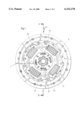
- FIG. 1 shows the end view of a clutch disk having a torsion vibration damper according to an embodiment of the present invention
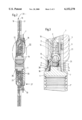
- FIG. 2 shows a section of the clutch disk of FIG. 1 along the line II--II;
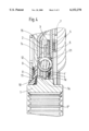
- FIG. 3 shows an enlarged representation of the area of FIG. 2 indicated by the arrow III;
- FIG. 4 shows the same area as FIG. 3 of another embodiment of a clutch disk according to the present invention.
- FIGS. 1-3 show a clutch disk 20 of a motor vehicle friction clutch with a hub 1 which can be centrally placed on an input shaft of a gearbox (the input shaft is not shown) so that the hub is rotationally fixed and axially moveable on the input shaft via internal splines 1".
- Torque is transmitted to the clutch disk 20 and introduced into the torsional vibration damping device by a friction disk 28 with lining springs 19 arranged between friction linings 17, 18.
- a main damper 27 having circumferentially arranged torsion springs 16 and an idling damper 29 (initial damper) likewise having circumferentially arranged torsion springs 21 and located radially further inward are provided for torsional damping.
- the hub 1 includes radially external splines 1' which are formed by individual external splines 1b.
- An axial stop surface 1c is configured on the splines 1b.
- Cover plates 7, 12 are provided on each side of the splines 1' and these cover plates 7, 12 are connected together in a rotationally fixed manner by distance pieces 13.
- Two drive disks 5, 14, two side disks 3, 15 and an inner part 2 are all arranged coaxially between the cover plates 7, 12.
- the inner part 2 arranged coaxially between the side disks 3, 15 forms an intermediate disk.
- the torsion springs 21 of the initial damper are arranged in windows 22 provided in the drive disks 5, 14 and in the side disks 3, 5 and the intermediate disk 2.
- the cover plates 7, 12 likewise have windows 23 for accommodating the torsional springs 16.
- the external splines 1b of the hub 1 have shoulders or humps 1a which protrude radially outward and form an axial stop surface for the radially inner part of the intermediate disk 2.
- the external splines 1b may have a stepped configuration instead of the shoulders or humps 1a.
- a support ring 8 is arranged on the hub 1 for supporting the cover plate 12 via splines 26 on the support ring 8 so that the cover plate 12 is rotationally fixed and axially movably arranged on the support ring 8.
- the external splines 1' support the support ring 8 via an annular spring 10 and a steel disk 11.
- a spring 9, which is configured as a plate spring and applies an axially directed force, is provided between the support ring 8 and the cover plate 12.
- Each of the drive disks 5, 14, the side disks 3, 15 and the intermediate disk 2 are connected with some clearance play via internal splines, to the splines 1' of the hub 1 so that they rotate with the latter.
- a plate spring 4 with individual spring tongues 4' protruding axially and radially outward is provided between the drive disk 5 and the side disk 3.
- the side disk 3 presses the intermediate disk 2 axially against the hump 1a of the splines 1b under the urgency of this plate spring 4.
- a friction ring 6 made of a plastic material, and whose radius of action is larger than the radius of action of the springs 4, 9, is provided between the drive disk 5 and the cover plate 7.
- the cover plate 7 overlaps the friction disk 6 for a short portion radially inward and then terminates so that a free space 25 is left in the radial direction between the hub 1 and the cover plate 7.
- the hub 1 is axially secured by the intermediate disk 2 which is in contact with the humps 1a so that a free axial space is created by the free annular space 25 retained between the cover plate 7 and the hub 1.
- the free space 25 extends in the radial direction beyond the torsion springs 21 of the initial damper.
- the force path of the main damper friction device takes place via the support ring 8, the drive disk 14, the drive disk 5, the friction ring 6, the cover plate 7, the distance pieces 13 and the cover plate 12.
- the force path in the friction device of the initial damper 29 takes place by the annular spring 10, which is supported on the disk 11, the hub 1, the intermediate disk 2, the side disk 3, the plate spring 4, the drive disk 5, the friction ring 6, the cover plate 7, the distance pieces 13, the cover plate 12 and the support ring 8.
Abstract
Description
Claims (10)
Applications Claiming Priority (2)
| Application Number | Priority Date | Filing Date | Title |
|---|---|---|---|
| DE19830498A DE19830498B4 (en) | 1998-07-08 | 1998-07-08 | Torsionsschwingungsdämpfungseinrichtung |
| DE19830498 | 1998-07-08 |
Publications (1)
| Publication Number | Publication Date |
|---|---|
| US6152278A true US6152278A (en) | 2000-11-28 |
Family
ID=7873331
Family Applications (1)
| Application Number | Title | Priority Date | Filing Date |
|---|---|---|---|
| US09/349,434 Expired - Fee Related US6152278A (en) | 1998-07-08 | 1999-07-07 | Torsional vibration damping device |
Country Status (2)
| Country | Link |
|---|---|
| US (1) | US6152278A (en) |
| DE (1) | DE19830498B4 (en) |
Cited By (1)
| Publication number | Priority date | Publication date | Assignee | Title |
|---|---|---|---|---|
| US20200292006A1 (en) * | 2019-03-15 | 2020-09-17 | Exedy Corporation | Damper device |
Families Citing this family (1)
| Publication number | Priority date | Publication date | Assignee | Title |
|---|---|---|---|---|
| DE102004012086A1 (en) * | 2003-03-20 | 2004-09-30 | Zf Sachs Ag | Torsional oscillation damper used in vehicle clutch system includes supports for transmission components, acting in different axial directions |
Citations (4)
| Publication number | Priority date | Publication date | Assignee | Title |
|---|---|---|---|---|
| US4688666A (en) * | 1985-02-08 | 1987-08-25 | Valeo | Clutch friction disc |
| US4700821A (en) * | 1984-11-23 | 1987-10-20 | Luk Lamellen Und Kupplungsbau Gmbh | Clutch plate |
| DE19613574A1 (en) * | 1996-04-04 | 1997-10-09 | Fichtel & Sachs Ag | Torsional vibration damper |
| US5909790A (en) * | 1996-07-25 | 1999-06-08 | Fichtel & Sachs Ag | Clutch plate with friction disk supported by idle spring and hub |
Family Cites Families (1)
| Publication number | Priority date | Publication date | Assignee | Title |
|---|---|---|---|---|
| GB8708536D0 (en) * | 1987-04-09 | 1987-05-13 | Automotive Prod Plc | Torsional vibration damper |
-
1998
- 1998-07-08 DE DE19830498A patent/DE19830498B4/en not_active Expired - Fee Related
-
1999
- 1999-07-07 US US09/349,434 patent/US6152278A/en not_active Expired - Fee Related
Patent Citations (5)
| Publication number | Priority date | Publication date | Assignee | Title |
|---|---|---|---|---|
| US4700821A (en) * | 1984-11-23 | 1987-10-20 | Luk Lamellen Und Kupplungsbau Gmbh | Clutch plate |
| US4688666A (en) * | 1985-02-08 | 1987-08-25 | Valeo | Clutch friction disc |
| DE19613574A1 (en) * | 1996-04-04 | 1997-10-09 | Fichtel & Sachs Ag | Torsional vibration damper |
| US5988343A (en) * | 1996-04-04 | 1999-11-23 | Fichtel & Sachs Ag | Clutch disc with a torsional vibration damper for a motor vehicle friction clutch |
| US5909790A (en) * | 1996-07-25 | 1999-06-08 | Fichtel & Sachs Ag | Clutch plate with friction disk supported by idle spring and hub |
Cited By (2)
| Publication number | Priority date | Publication date | Assignee | Title |
|---|---|---|---|---|
| US20200292006A1 (en) * | 2019-03-15 | 2020-09-17 | Exedy Corporation | Damper device |
| US11619282B2 (en) * | 2019-03-15 | 2023-04-04 | Exedy Corporation | Damper device |
Also Published As
| Publication number | Publication date |
|---|---|
| DE19830498A1 (en) | 2000-01-13 |
| DE19830498B4 (en) | 2005-05-04 |
Similar Documents
| Publication | Publication Date | Title |
|---|---|---|
| US8640449B2 (en) | Hydrodynamic torque converter having a vibration absorber and torsional vibration damper | |
| US9140348B2 (en) | Hydrodynamic coupling arrangement, in particular a torque converter | |
| JP5223999B2 (en) | Torsional vibration damping device | |
| US4254855A (en) | Coaxial spring damper drive | |
| WO2012104926A1 (en) | Torsional vibration damping device | |
| JP3558462B2 (en) | Flywheel assembly | |
| US7195111B2 (en) | Clutch device having a clutch damper and dual-mass flywheel assembly | |
| US5885160A (en) | Torsion damping device having circumferentially acting resilient members of different stiffness | |
| JPH0141849B2 (en) | ||
| US6488139B1 (en) | Damper mechanism | |
| JPS62204053A (en) | Automobile with torque converter between internal combustionengine and gearing | |
| US6152278A (en) | Torsional vibration damping device | |
| US4741423A (en) | Clutch disc for a friction clutch | |
| US6872142B2 (en) | Damper mechanism | |
| JP4709760B2 (en) | Friction clutch for automobile with multi-functional means | |
| JP4277507B2 (en) | Torque fluctuation absorber | |
| US6299540B1 (en) | Torsional vibration damping device in the drive train of a motor vehicle | |
| CN113492666A (en) | Hybrid drive train | |
| US6223625B1 (en) | Torque transmitting and torsion damping apparatus for use in motor vehicles | |
| GB2315315A (en) | Friction clutch predamper. | |
| JP4244438B2 (en) | Torque fluctuation absorber | |
| CN113557373A (en) | Vehicle damper and vehicle | |
| GB2315533A (en) | Motor vehicle clutch plate | |
| CN115681406A (en) | Vibration damping device | |
| CN115199703A (en) | Torsional vibration damper with centering device |
Legal Events
| Date | Code | Title | Description |
|---|---|---|---|
| AS | Assignment |
Owner name: MANNESMANN SACHS AG, GERMANY Free format text: ASSIGNMENT OF ASSIGNORS INTEREST;ASSIGNOR:WACK, ERWIN;REEL/FRAME:010091/0642 Effective date: 19990702 |
|
| FEPP | Fee payment procedure |
Free format text: PAYOR NUMBER ASSIGNED (ORIGINAL EVENT CODE: ASPN); ENTITY STATUS OF PATENT OWNER: LARGE ENTITY |
|
| FPAY | Fee payment |
Year of fee payment: 4 |
|
| AS | Assignment |
Owner name: ZF FRIEDRICHSHAFEN AG, GERMANY Free format text: ASSIGNMENT OF ASSIGNORS INTEREST;ASSIGNOR:ZF SACHS AG;REEL/FRAME:016824/0376 Effective date: 20050622 Owner name: ZF SACHS AG, GERMANY Free format text: CHANGE OF NAME;ASSIGNOR:MANNESMANN SACHS AG;REEL/FRAME:016871/0474 Effective date: 20011127 |
|
| FPAY | Fee payment |
Year of fee payment: 8 |
|
| REMI | Maintenance fee reminder mailed | ||
| LAPS | Lapse for failure to pay maintenance fees | ||
| STCH | Information on status: patent discontinuation |
Free format text: PATENT EXPIRED DUE TO NONPAYMENT OF MAINTENANCE FEES UNDER 37 CFR 1.362 |
|
| FP | Lapsed due to failure to pay maintenance fee |
Effective date: 20121128 |