US6152005A - Method of punching a punch guide hole in a blank holder of a punch assembly a punch assembly and a blank holder - Google Patents
Method of punching a punch guide hole in a blank holder of a punch assembly a punch assembly and a blank holder Download PDFInfo
- Publication number
- US6152005A US6152005A US08/886,444 US88644497A US6152005A US 6152005 A US6152005 A US 6152005A US 88644497 A US88644497 A US 88644497A US 6152005 A US6152005 A US 6152005A
- Authority
- US
- United States
- Prior art keywords
- blank holder
- punch
- punch guide
- guide
- punching
- Prior art date
- Legal status (The legal status is an assumption and is not a legal conclusion. Google has not performed a legal analysis and makes no representation as to the accuracy of the status listed.)
- Expired - Fee Related
Links
- 238000004080 punching Methods 0.000 title claims abstract description 23
- 238000000034 method Methods 0.000 title abstract description 7
- 230000002093 peripheral effect Effects 0.000 claims abstract description 14
- 239000002184 metal Substances 0.000 claims description 3
- 229920005989 resin Polymers 0.000 claims description 2
- 239000011347 resin Substances 0.000 claims description 2
- 238000010276 construction Methods 0.000 description 5
- 230000006866 deterioration Effects 0.000 description 2
- 239000000463 material Substances 0.000 description 2
- 230000000414 obstructive effect Effects 0.000 description 1
- 230000000717 retained effect Effects 0.000 description 1
- 239000007779 soft material Substances 0.000 description 1
- 229920003002 synthetic resin Polymers 0.000 description 1
- 239000000057 synthetic resin Substances 0.000 description 1
Images
Classifications
-
- B—PERFORMING OPERATIONS; TRANSPORTING
- B21—MECHANICAL METAL-WORKING WITHOUT ESSENTIALLY REMOVING MATERIAL; PUNCHING METAL
- B21D—WORKING OR PROCESSING OF SHEET METAL OR METAL TUBES, RODS OR PROFILES WITHOUT ESSENTIALLY REMOVING MATERIAL; PUNCHING METAL
- B21D45/00—Ejecting or stripping-off devices arranged in machines or tools dealt with in this subclass
- B21D45/003—Ejecting or stripping-off devices arranged in machines or tools dealt with in this subclass in punching machines or punching tools
- B21D45/006—Stripping-off devices
-
- B—PERFORMING OPERATIONS; TRANSPORTING
- B21—MECHANICAL METAL-WORKING WITHOUT ESSENTIALLY REMOVING MATERIAL; PUNCHING METAL
- B21D—WORKING OR PROCESSING OF SHEET METAL OR METAL TUBES, RODS OR PROFILES WITHOUT ESSENTIALLY REMOVING MATERIAL; PUNCHING METAL
- B21D37/00—Tools as parts of machines covered by this subclass
- B21D37/10—Die sets; Pillar guides
- B21D37/12—Particular guiding equipment, e.g. pliers; Special arrangements for interconnection or cooperation of dies
-
- B—PERFORMING OPERATIONS; TRANSPORTING
- B21—MECHANICAL METAL-WORKING WITHOUT ESSENTIALLY REMOVING MATERIAL; PUNCHING METAL
- B21D—WORKING OR PROCESSING OF SHEET METAL OR METAL TUBES, RODS OR PROFILES WITHOUT ESSENTIALLY REMOVING MATERIAL; PUNCHING METAL
- B21D28/00—Shaping by press-cutting; Perforating
- B21D28/24—Perforating, i.e. punching holes
- B21D28/34—Perforating tools; Die holders
-
- Y—GENERAL TAGGING OF NEW TECHNOLOGICAL DEVELOPMENTS; GENERAL TAGGING OF CROSS-SECTIONAL TECHNOLOGIES SPANNING OVER SEVERAL SECTIONS OF THE IPC; TECHNICAL SUBJECTS COVERED BY FORMER USPC CROSS-REFERENCE ART COLLECTIONS [XRACs] AND DIGESTS
- Y10—TECHNICAL SUBJECTS COVERED BY FORMER USPC
- Y10T—TECHNICAL SUBJECTS COVERED BY FORMER US CLASSIFICATION
- Y10T83/00—Cutting
- Y10T83/202—With product handling means
- Y10T83/2092—Means to move, guide, or permit free fall or flight of product
- Y10T83/2096—Means to move product out of contact with tool
- Y10T83/2135—Moving stripper timed with tool stroke
- Y10T83/215—Carried by moving tool element or its support
- Y10T83/2155—Stripper biased against product
- Y10T83/2157—Elastomeric stripper contacting product
-
- Y—GENERAL TAGGING OF NEW TECHNOLOGICAL DEVELOPMENTS; GENERAL TAGGING OF CROSS-SECTIONAL TECHNOLOGIES SPANNING OVER SEVERAL SECTIONS OF THE IPC; TECHNICAL SUBJECTS COVERED BY FORMER USPC CROSS-REFERENCE ART COLLECTIONS [XRACs] AND DIGESTS
- Y10—TECHNICAL SUBJECTS COVERED BY FORMER USPC
- Y10T—TECHNICAL SUBJECTS COVERED BY FORMER US CLASSIFICATION
- Y10T83/00—Cutting
- Y10T83/929—Tool or tool with support
- Y10T83/9411—Cutting couple type
- Y10T83/9423—Punching tool
- Y10T83/9428—Shear-type male tool
-
- Y—GENERAL TAGGING OF NEW TECHNOLOGICAL DEVELOPMENTS; GENERAL TAGGING OF CROSS-SECTIONAL TECHNOLOGIES SPANNING OVER SEVERAL SECTIONS OF THE IPC; TECHNICAL SUBJECTS COVERED BY FORMER USPC CROSS-REFERENCE ART COLLECTIONS [XRACs] AND DIGESTS
- Y10—TECHNICAL SUBJECTS COVERED BY FORMER USPC
- Y10T—TECHNICAL SUBJECTS COVERED BY FORMER US CLASSIFICATION
- Y10T83/00—Cutting
- Y10T83/929—Tool or tool with support
- Y10T83/9457—Joint or connection
- Y10T83/9473—For rectilinearly reciprocating tool
- Y10T83/9476—Tool is single element with continuous cutting edge [e.g., punch, etc.]
Definitions
- the present invention relates to a method of punching a punch guide hole in a blank holder of a punch assembly which is used in a state of being attached to a punch holder in a punch press such as a turret punch press, a punch assembly and a blank holder.
- a punch assembly in the related art has disclosed the construction that it comprises a punch body having a punching portion at its lower end portion being vertically movably housed in a punch guide which is vertically movably supported onto a turret-like punch holder of a turret punch press, and a plastic blank holder being removably fitted into a fitting groove formed in a lower end portion of a punch guide.
- a cylindrical projecting portion of the blank holder is fitted into the fitting groove of the punch guide, and thereafter, the punch body is inserted into the punch guide. And then, the punching portion of the punch body is subjected to punching so as to punch a punch guide hole in the blank holder.
- the blank holder is made of a relatively soft material, there is a problem that the blank holder does not act and not exhibit its function and is lack of durability.
- a method of punching a punch guide hole in a blank holder while attaching the blank holder to a lower end portion of a punch guide in a punch assembly constructed in a manner that a punch body having a punching portion at its lower end portion is vertically movably housed in the punch guide vertically movably supported onto a punch holder comprising the steps of: fitting lightly a distal end portion of a cylindrical projecting portion of the blank holder into a fitting groove formed in the lower end portion of the punch guide so that the distal end portion is momentarily held in the blank holder; and fitting forcedly the projecting portion of the blank holder into the fitting groove formed in the punch guide and punching the punch guide hole in the blank holder by pressing a punch head of a punch body of the punch assembly so that the punch guide descends and presses the blank holder against a die provided opposite to the blank holder.
- the blank holder is fitted into the fitting groove by taking use of a downward pressing force of a striker, etc., so that attachment of the blank holder to the punch guide and punching of the punch guide hole of the blank holder can be readily achieved.
- a punch assembly comprising: a punch guide vertically movably supported onto a punch holder; a punch body having a punching portion at its lower end portion vertically movably housed in the punch guide; and a blank holder is removably fitted into a fitting groove formed in a lower end portion of the punch guide, wherein the punch guide or the blank holder being formed with an inclined plane constructed so that a distance between the punch guide and the blank holder is widened toward the outside thereof, at part of an outer peripheral face on a lower end portion of the punch guide or part of an upper face of a flange of the blank holder.
- the inclined plane is formed on the outer peripheral face on a lower end portion of the punch guide or on the upper face of the flange of the blank holder so as to gradually guide the pawls of the removal tool between the lower end portion of the punch guide and the flange of the blank holder.
- a component in a direction of removing the blank holder from the punch guide acts thereon, so that the removal of the blank holder can be readily achieved, as described above.
- the punch assembly further comprises an elastic member is interposed between the punch guide and the blank holder, wherein the blank holder is retained onto the punch guide by means of the elastic member.
- attachment of the blank holder to the punch guide can be readily achieved regardless of material quality of the blank holder. Also, there is no problem such that protrusions of the blank holder is not chipped off when attaching the blank holder to the punch guide.
- the blank holder is made of a rigid resin or metal, and the lower end face of the punch guide and the flange of the blank holder face each other.
- the blank holder sufficiently acts or exhibits its function in operating.
- a sixth aspect of the present invention as it depends from the second, third, fourth or fifth aspect, wherein the flange of the blank holder has a thickness thicker than a bottom portion on an inside of the projecting portion formed on the blank holder.
- the projecting portion of the blank holder is securely fitted into a fitting groove formed in the punch guide while punching of a punch guide hole being carried out. Therefore, the punch guide hole can be accurately punched in the blank holder.
- a blank holder attached to a lower end portion of a punch guide of a punch assembly comprising: a blank holder being formed with a fitting projecting portion being capable of fitting into a fitting groove formed in the lower end portion of the punch guide; and an elastic member at an outer peripheral face of the projecting portion being capable of fitting into a stopper concave portion having an inner circumferential groove formed in the punch guide.
- the blank holder can be readily fitted into the groove formed in the punch guide.
- the blank holder further comprises a flange on the outside of the projecting portion formed so as to have a thickness thicker than the bottom portion on the inner side of the projecting portion.
- the punch guide hole can be accurately punched in the blank holder.
- a ninth aspect of the present invention as it depends from the seventh or eighth aspect, wherein the flange is at least symmetrically formed with an inclined plane at its upper face.
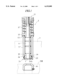
- FIG. 1 is a cross sectional view of a punch assembly of the present invention
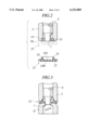
- FIG. 2 is an explanatory view of an operation for attaching a blank holder onto a punch guide
- FIG. 3 is an explanatory view of an operation for punching a punch guide hole in the blank holder together with the blank holder attachment;
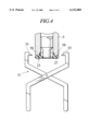
- FIG. 4 is an explanatory view of an operation for removing the blank holder from the punch guide
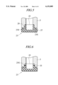
- FIG. 5 is an explanatory view showing a second embodiment of the present invention.
- FIG. 6 is an explanatory view showing a third embodiment of the present invention.
- a punch assembly 1 of the present invention is provided with a cylindrical punch guide 5 which is vertically movably supported onto a turret-like punch holder 3 of a punch press, for example, a turret punch press.
- the punch guide 5 is supported onto the punch holder by means of a lifter spring (not shown) so as to be situated at a predetermined height, and descends against a force by the lifter spring.
- a punch body 9 having a punch portion 7 at its lower end portion is vertically movably housed in the punch guide 5.
- a stripper spring 17 is elastically interposed between a punch head 11 which is screwed into an upper end portion of the punch body 9 and a retainer collar 15 which is removably attached onto an upper portion of the punch guide 5 via a O ring 13.
- the aforesaid punch guide 5 is provided with a fitting groove 19 at its lower end portion.
- An inner peripheral face of the fitting groove 19 is formed with an inner circumferential groove 21 which is one example as a stopper concave portion.
- the fitting groove 19 is removably fitted with a cylindrical projecting portion 25 of a blank holder 23.
- the blank holder 23 is made of a synthetic resin or proper metal. As shown in FIG. 2, the blank holder 23 has a disc-like flange 27 and the aforesaid projecting portion 25 which projects from the flange 27. An outer peripheral face of the projecting portion 25 is formed with an annular protrusion 29 which is one example as a stopper convex portion capable of engaging with the inner circumferential groove 21 formed in the punch guide 5.
- a bottom portion 25B on the inner side of the projecting portion 25 is formed so as to have a thickness thinner than a thickness of the outer-side flange 27 of the projecting portion 25.
- the projecting portion 25 is provided with proper slits 25S in number so that the projecting portion 25 is easy to be elastically deformed when fitting the projecting portion 25 of the blank holder 23 into the fitting groove 19 of the punch guide 5.
- the lower end portion of the groove 19 and the peripheral edge on an upper portion of the projecting portion 25 are subjected to chamfering so as to form a taper guide face therein.
- opposite sides of the lower end portion of punch guide 5 are symmetrically formed with an inclined plane 5S so that a distance between the blank holder 23 and the punch guide 5 becomes wider toward the outside thereof. Also, if the inclined plane 5S is formed over the entire circumstance of the punch guide 5, there is formed a conical taper face.
- the punch head 11 is pressed down by means of the ram, striker or the like so that the punch body 9 descends, and simultaneously, the punch guide 5 descends together with the punch body 9 against a force of the lifter spring (not shown).
- the projecting portion 25 of the blank holder 23 is forcedly fitted into the groove 19 of the punch guide 5 while a punch guide hole 23G being punched in the blank holder 23 by punching of the aforesaid punching portion 7 (see FIGS. 1 and 3).
- the flange 27 is formed thicker than the thickness of the bottom portion 25B on the inner side of the projecting portion 25 of the blank holder 23, the projecting portion 25 is securely fitted into the groove 19, and punching of the punch guide hole 23G is carried out in a state that the flange 27 is sandwiched in between the die D and the lower end portion of the punch guide 5.
- the blank holder 23 has been used for a long time in a state that the projecting portion 25 of the blank holder 23 is fitted into the groove 19 of the punch guide 5. Thereafter, in the case where the using blank holder 23 is replaced with a new blank holder due to a deterioration or damage caused therein, a pair of opening and closing pawl portions 33 provided in a removal tool 31 is interposed between the inclined plane 5S formed in the punch guide 5 and the flange 27 of the blank holder, and then, a distance between the pair of pawl portions 33 gradually makes narrow.
- the blank holder 23 is removed from the punch guide 5, and thereafter, a new blank holder 23 is temporarily held in the lower end portion of the punch guide 5 as described before. And then, when the aforesaid operation is repeated, the new blank holder 23 is attached with respect to the punch guide while the punch hole 23G being punched therein.
- an upper face of the flange 27 of the blank holder 23 may be formed with an inclination plane 23S instead of forming the inclined plane 5S in the lower end portion of the punch guide 5.
- the inclined plane may be formed both in the punch guide 5 and in the blank holder 23.
- the outer peripheral face of the projecting portion of the blank holder 23 is formed with a circumferential groove 25G.
- the circumferential groove 25G may be provided with an elastic member such as an O ring, etc.
- the attachment of the blank holder 23 can be readily achieved even in the case where the projecting portion 25 is hard to be elastically deformed.
- the elastic member 35 exhibits a function as an annular stopper convex portion.
- the elastic member 35 is elastically deformed when being fitted into to the groove 19. Therefore, this serves to prevent the elastic member 35 from being chipped off by an edge portion of the groove 19.
Priority Applications (1)
| Application Number | Priority Date | Filing Date | Title |
|---|---|---|---|
| US09/221,150 US6311594B1 (en) | 1996-07-03 | 1998-12-28 | Punch guiding apparatus and stripper plate used therefor |
Applications Claiming Priority (2)
| Application Number | Priority Date | Filing Date | Title |
|---|---|---|---|
| JP17381696A JP3222065B2 (ja) | 1996-07-03 | 1996-07-03 | パンチ組立体及び板押え |
| JPP8-173816 | 1996-07-03 |
Related Child Applications (1)
| Application Number | Title | Priority Date | Filing Date |
|---|---|---|---|
| US09/221,150 Continuation-In-Part US6311594B1 (en) | 1996-07-03 | 1998-12-28 | Punch guiding apparatus and stripper plate used therefor |
Publications (1)
| Publication Number | Publication Date |
|---|---|
| US6152005A true US6152005A (en) | 2000-11-28 |
Family
ID=15967694
Family Applications (1)
| Application Number | Title | Priority Date | Filing Date |
|---|---|---|---|
| US08/886,444 Expired - Fee Related US6152005A (en) | 1996-07-03 | 1997-07-01 | Method of punching a punch guide hole in a blank holder of a punch assembly a punch assembly and a blank holder |
Country Status (7)
| Country | Link |
|---|---|
| US (1) | US6152005A (ja) |
| EP (1) | EP0815979B1 (ja) |
| JP (1) | JP3222065B2 (ja) |
| KR (1) | KR100478388B1 (ja) |
| CN (1) | CN1080607C (ja) |
| DE (1) | DE69719118T2 (ja) |
| TW (1) | TW348108B (ja) |
Cited By (11)
| Publication number | Priority date | Publication date | Assignee | Title |
|---|---|---|---|---|
| US6341548B1 (en) * | 1998-04-17 | 2002-01-29 | Brother Kogyo Kabushiki Kaisha | Device for adjusting distance of cutting blade from workpiece sheet |
| US6622601B2 (en) * | 2000-01-26 | 2003-09-23 | Hitachi Metals Ltd. | Punch unit for punching a hole in a soft metal sheet |
| US6698324B2 (en) | 2000-01-26 | 2004-03-02 | Hitachi Metals, Ltd. | Punch unit for punching a hole in a soft metal sheet |
| US20070034069A1 (en) * | 2005-07-04 | 2007-02-15 | Amada Company, Limited | Upper tool device and punch therefor |
| US20110185874A1 (en) * | 2010-01-29 | 2011-08-04 | Jason Blair | Punch Press |
| JP2014133261A (ja) * | 2013-01-11 | 2014-07-24 | F C C:Kk | プレス部品の成形方法、プレス部品の製造方法およびプレス部品の成形用金型 |
| CN104550435A (zh) * | 2015-01-21 | 2015-04-29 | 常州机电职业技术学院 | 冲孔落料模具 |
| CN104588504A (zh) * | 2015-01-28 | 2015-05-06 | 苏黎 | 一种合金金属轴套预备件冲孔、修边模具 |
| CN105855400A (zh) * | 2016-06-08 | 2016-08-17 | 程桂红 | 一种冲压模具 |
| US20170087736A1 (en) * | 2015-09-30 | 2017-03-30 | Tkr Spezialwerkzeuge Gmbh | Hydraulic Punch Machine, and Punch Carrier for a Punch Machine |
| US20180200905A1 (en) * | 2017-01-13 | 2018-07-19 | Chin-Wen Yen | Punching device |
Families Citing this family (18)
| Publication number | Priority date | Publication date | Assignee | Title |
|---|---|---|---|---|
| JP2000051979A (ja) * | 1998-08-04 | 2000-02-22 | Amada Metrecs Co Ltd | パンチガイド装置およびそれに用いるストリッパプレート |
| CN1106235C (zh) * | 2000-06-07 | 2003-04-23 | 智豪机械(深圳)有限公司 | 带有压料装置的冲床液压冲头机构 |
| US6895849B2 (en) * | 2002-06-07 | 2005-05-24 | Wilson Tool International, Inc. | Stripper plate retention system |
| JP4902286B2 (ja) * | 2006-07-25 | 2012-03-21 | 株式会社アマダ | パンチ組立体 |
| US8327745B2 (en) | 2008-11-06 | 2012-12-11 | Wilson Tool International Inc. | Punch assemblies and methods for modifying |
| US8707841B2 (en) | 2011-11-11 | 2014-04-29 | Wilson Tool International Inc. | Punch assemblies and universal punch therefor |
| US9409223B2 (en) | 2011-11-11 | 2016-08-09 | Wilson Tool International Inc. | Punch assemblies and universal punch therefor |
| JP6091254B2 (ja) * | 2013-02-28 | 2017-03-08 | 株式会社アマダホールディングス | パンチ金型 |
| CN103212660B (zh) * | 2013-04-10 | 2014-09-17 | 盐城理研精密锻造有限公司 | 一种导向模具 |
| CN104741448A (zh) * | 2013-12-27 | 2015-07-01 | 旭景川宇机械(天津)有限公司 | 消音器法兰的制备工艺 |
| US10646913B2 (en) | 2015-02-09 | 2020-05-12 | Mate Precision Tooling, Inc. | Punch assembly with replaceable punch tip |
| USD822725S1 (en) | 2015-12-31 | 2018-07-10 | Mate Precision Tooling, Inc. | Punch insert |
| USD820328S1 (en) | 2015-12-31 | 2018-06-12 | Mate Precision Tooling, Inc. | Punch insert |
| KR101896786B1 (ko) * | 2016-10-20 | 2018-09-07 | 현대자동차주식회사 | 실링캡 삽입 장치 |
| CN108723179B (zh) * | 2017-04-24 | 2020-09-01 | Ykk株式会社 | 成型机及芯轴的更换方法 |
| CN108818736B (zh) * | 2018-05-29 | 2023-12-08 | 舒普智能技术股份有限公司 | 一种全自动冲孔机 |
| US11667051B2 (en) | 2020-09-23 | 2023-06-06 | Wilson Tool International Inc. | Punch assemblies and toolless systems thereof for tip retention and release |
| CN113751577A (zh) * | 2021-08-17 | 2021-12-07 | 杭州富阳中恒电气有限公司 | 一种用于加工能源连接件的简易上模退料组件 |
Citations (7)
| Publication number | Priority date | Publication date | Assignee | Title |
|---|---|---|---|---|
| JPS5329586A (en) * | 1976-08-30 | 1978-03-18 | Pirelli | Composite band for coaxial screen of cable and method of manufacturing thereof and power cable containing composite band |
| US4246815A (en) * | 1979-10-15 | 1981-01-27 | Danly Machine Corporation | Volumetrically deformed polymeric support for punches |
| US4261237A (en) * | 1979-03-16 | 1981-04-14 | Houdaille Industries, Inc. | Rigidly supported molded plastics material punch guide and stripper |
| US4929276A (en) * | 1989-05-22 | 1990-05-29 | Murata Wiedemann, Inc. | Multitool punch holder |
| US5176057A (en) * | 1991-10-11 | 1993-01-05 | Murata Machinery Limited | Punch holder with stripper arrangement |
| US5438897A (en) * | 1993-12-29 | 1995-08-08 | Murata Machinery, Ltd., Machine Tool Division | Stripper arrangement for a punch holder |
| US5701790A (en) * | 1993-07-28 | 1997-12-30 | Amada Metrecs Company, Limited | Upper tool for a press |
Family Cites Families (8)
| Publication number | Priority date | Publication date | Assignee | Title |
|---|---|---|---|---|
| US3496818A (en) * | 1967-09-11 | 1970-02-24 | Porter Precision Products Inc | Guide bushing for die sets |
| GB1251843A (ja) * | 1968-02-03 | 1971-11-03 | ||
| US4248111A (en) * | 1979-07-16 | 1981-02-03 | Wilson Tool Company | Punch guide assembly |
| SU1676718A1 (ru) * | 1989-06-06 | 1991-09-15 | Тульский Политехнический Институт | Узел креплени быстросменного пуансона штампа |
| SU1761348A1 (ru) * | 1990-07-09 | 1992-09-15 | Самарское моторостроительное производственное объединение им.М.В.Фрунзе | Штамп дл пробивки отверстий |
| JP2669787B2 (ja) * | 1993-10-01 | 1997-10-29 | 株式会社アマダメトレックス | パンチング金型のストリッパー装置および同装置を用いたパンチ組立体 |
| JPH07214191A (ja) * | 1994-02-02 | 1995-08-15 | Iijima Seimitsu Kogyo Kk | プレス金型およびプレス成形方法 |
| JPH07275967A (ja) * | 1994-04-05 | 1995-10-24 | Amada Co Ltd | パンチ金型調整処理装置 |
-
1996
- 1996-07-03 JP JP17381696A patent/JP3222065B2/ja not_active Expired - Fee Related
-
1997
- 1997-07-01 US US08/886,444 patent/US6152005A/en not_active Expired - Fee Related
- 1997-07-02 DE DE69719118T patent/DE69719118T2/de not_active Expired - Fee Related
- 1997-07-02 EP EP97111057A patent/EP0815979B1/en not_active Expired - Lifetime
- 1997-07-02 TW TW086109308A patent/TW348108B/zh not_active IP Right Cessation
- 1997-07-03 CN CN97117147A patent/CN1080607C/zh not_active Expired - Fee Related
- 1997-07-03 KR KR1019970030782A patent/KR100478388B1/ko not_active IP Right Cessation
Patent Citations (7)
| Publication number | Priority date | Publication date | Assignee | Title |
|---|---|---|---|---|
| JPS5329586A (en) * | 1976-08-30 | 1978-03-18 | Pirelli | Composite band for coaxial screen of cable and method of manufacturing thereof and power cable containing composite band |
| US4261237A (en) * | 1979-03-16 | 1981-04-14 | Houdaille Industries, Inc. | Rigidly supported molded plastics material punch guide and stripper |
| US4246815A (en) * | 1979-10-15 | 1981-01-27 | Danly Machine Corporation | Volumetrically deformed polymeric support for punches |
| US4929276A (en) * | 1989-05-22 | 1990-05-29 | Murata Wiedemann, Inc. | Multitool punch holder |
| US5176057A (en) * | 1991-10-11 | 1993-01-05 | Murata Machinery Limited | Punch holder with stripper arrangement |
| US5701790A (en) * | 1993-07-28 | 1997-12-30 | Amada Metrecs Company, Limited | Upper tool for a press |
| US5438897A (en) * | 1993-12-29 | 1995-08-08 | Murata Machinery, Ltd., Machine Tool Division | Stripper arrangement for a punch holder |
Cited By (18)
| Publication number | Priority date | Publication date | Assignee | Title |
|---|---|---|---|---|
| US6341548B1 (en) * | 1998-04-17 | 2002-01-29 | Brother Kogyo Kabushiki Kaisha | Device for adjusting distance of cutting blade from workpiece sheet |
| US6622601B2 (en) * | 2000-01-26 | 2003-09-23 | Hitachi Metals Ltd. | Punch unit for punching a hole in a soft metal sheet |
| US6698324B2 (en) | 2000-01-26 | 2004-03-02 | Hitachi Metals, Ltd. | Punch unit for punching a hole in a soft metal sheet |
| US20070034069A1 (en) * | 2005-07-04 | 2007-02-15 | Amada Company, Limited | Upper tool device and punch therefor |
| US20080202307A1 (en) * | 2005-07-04 | 2008-08-28 | Amada Company, Limited | Upper tool device and punch therefor |
| US7802506B2 (en) * | 2005-07-04 | 2010-09-28 | Amada Company, Limited | Upper tool device and punch therefor |
| US7958807B2 (en) * | 2005-07-04 | 2011-06-14 | Amada Company Limited | Upper tool device and punch therefor |
| US20110185874A1 (en) * | 2010-01-29 | 2011-08-04 | Jason Blair | Punch Press |
| JP2014133261A (ja) * | 2013-01-11 | 2014-07-24 | F C C:Kk | プレス部品の成形方法、プレス部品の製造方法およびプレス部品の成形用金型 |
| US10092940B2 (en) | 2013-01-11 | 2018-10-09 | Kabushiki Kaisha F.C.C. | Method for forming a pressed component, method for manufacturing a pressed component, and die apparatus for forming a pressed component |
| CN104550435A (zh) * | 2015-01-21 | 2015-04-29 | 常州机电职业技术学院 | 冲孔落料模具 |
| CN104588504A (zh) * | 2015-01-28 | 2015-05-06 | 苏黎 | 一种合金金属轴套预备件冲孔、修边模具 |
| CN104588504B (zh) * | 2015-01-28 | 2016-06-08 | 苏黎 | 一种合金金属轴套预备件冲孔、修边模具 |
| US20170087736A1 (en) * | 2015-09-30 | 2017-03-30 | Tkr Spezialwerkzeuge Gmbh | Hydraulic Punch Machine, and Punch Carrier for a Punch Machine |
| US10052780B2 (en) * | 2015-09-30 | 2018-08-21 | Tkr Spezialwerkzeuge Gmbh | Hydraulic punch machine, and punch carrier for a punch machine |
| CN105855400A (zh) * | 2016-06-08 | 2016-08-17 | 程桂红 | 一种冲压模具 |
| US20180200905A1 (en) * | 2017-01-13 | 2018-07-19 | Chin-Wen Yen | Punching device |
| US10603807B2 (en) * | 2017-01-13 | 2020-03-31 | Chin-Wen Yen | Punching device |
Also Published As
| Publication number | Publication date |
|---|---|
| CN1080607C (zh) | 2002-03-13 |
| DE69719118D1 (de) | 2003-03-27 |
| CN1176855A (zh) | 1998-03-25 |
| DE69719118T2 (de) | 2003-07-31 |
| TW348108B (en) | 1998-12-21 |
| JP3222065B2 (ja) | 2001-10-22 |
| EP0815979A3 (en) | 2001-05-30 |
| JPH1015897A (ja) | 1998-01-20 |
| EP0815979B1 (en) | 2003-02-19 |
| EP0815979A2 (en) | 1998-01-07 |
| KR100478388B1 (ko) | 2005-07-12 |
| KR980008383A (ko) | 1998-04-30 |
Similar Documents
| Publication | Publication Date | Title |
|---|---|---|
| US6152005A (en) | Method of punching a punch guide hole in a blank holder of a punch assembly a punch assembly and a blank holder | |
| US5492001A (en) | Method and apparatus for working burred portion of workpiece | |
| US6311594B1 (en) | Punch guiding apparatus and stripper plate used therefor | |
| EP0305029A2 (en) | Apparatus for reforming an end shell | |
| US20040240962A1 (en) | Captive screw | |
| EP0676279B1 (en) | Press forwardly feed die of metallic gasket | |
| US4993294A (en) | Punch holder with a stripper arrangement | |
| KR930009927B1 (ko) | 버어링 가공방법 | |
| EP0611188B1 (en) | Punching die | |
| US6000269A (en) | Method of forging and forging equipment | |
| JP4609811B2 (ja) | パンチ組立体 | |
| JPH11309520A (ja) | 先端が拡開した筒体部を有する部品の加工方法およびそれに用いる金型 | |
| EP0734799B1 (en) | Die unit for punching operations | |
| US5535657A (en) | Device for perforating paint can lids | |
| JP2750390B2 (ja) | 座金の製造方法 | |
| JPH0152089B2 (ja) | ||
| JP3754148B2 (ja) | 板材打抜き加工方法及び同方法に使用するパンチ金型 | |
| JPH0110110Y2 (ja) | ||
| US4483170A (en) | Press machine structure | |
| JPH1147852A (ja) | 合成樹脂成形品のスペーサー取付構造およびその工法 | |
| JPH0644486Y2 (ja) | 面取り付きプレス装置 | |
| JPH02112844A (ja) | バリ取り装置 | |
| KR820001679B1 (ko) | 외개와 내개를 가진 개봉이 용이한 용기뚜껑의 제조장치 | |
| KR820001678B1 (ko) | 외개와 내개를 가진 개봉이 용이한 용기 뚜껑의 제조방법 | |
| SU1074632A1 (ru) | Штамп совмещенного действи |
Legal Events
| Date | Code | Title | Description |
|---|---|---|---|
| AS | Assignment |
Owner name: AMADA METRECS COMPANY, LIMITED, JAPAN Free format text: ASSIGNMENT OF ASSIGNORS INTEREST;ASSIGNOR:OOTSUKA, YASUYUKI;REEL/FRAME:008663/0517 Effective date: 19970625 |
|
| FEPP | Fee payment procedure |
Free format text: PAYOR NUMBER ASSIGNED (ORIGINAL EVENT CODE: ASPN); ENTITY STATUS OF PATENT OWNER: LARGE ENTITY |
|
| FPAY | Fee payment |
Year of fee payment: 4 |
|
| REMI | Maintenance fee reminder mailed | ||
| LAPS | Lapse for failure to pay maintenance fees | ||
| STCH | Information on status: patent discontinuation |
Free format text: PATENT EXPIRED DUE TO NONPAYMENT OF MAINTENANCE FEES UNDER 37 CFR 1.362 |
|
| FP | Lapsed due to failure to pay maintenance fee |
Effective date: 20081128 |