US6151751A - Vacuum cleaner with dust bag retention flaps - Google Patents
Vacuum cleaner with dust bag retention flaps Download PDFInfo
- Publication number
- US6151751A US6151751A US09/297,806 US29780699A US6151751A US 6151751 A US6151751 A US 6151751A US 29780699 A US29780699 A US 29780699A US 6151751 A US6151751 A US 6151751A
- Authority
- US
- United States
- Prior art keywords
- vacuum cleaner
- dust bag
- cavity
- handle
- retention
- Prior art date
- Legal status (The legal status is an assumption and is not a legal conclusion. Google has not performed a legal analysis and makes no representation as to the accuracy of the status listed.)
- Expired - Lifetime
Links
Images
Classifications
-
- A—HUMAN NECESSITIES
- A47—FURNITURE; DOMESTIC ARTICLES OR APPLIANCES; COFFEE MILLS; SPICE MILLS; SUCTION CLEANERS IN GENERAL
- A47L—DOMESTIC WASHING OR CLEANING; SUCTION CLEANERS IN GENERAL
- A47L9/00—Details or accessories of suction cleaners, e.g. mechanical means for controlling the suction or for effecting pulsating action; Storing devices specially adapted to suction cleaners or parts thereof; Carrying-vehicles specially adapted for suction cleaners
- A47L9/10—Filters; Dust separators; Dust removal; Automatic exchange of filters
- A47L9/14—Bags or the like; Rigid filtering receptacles; Attachment of, or closures for, bags or receptacles
- A47L9/1427—Means for mounting or attaching bags or filtering receptacles in suction cleaners; Adapters
-
- A—HUMAN NECESSITIES
- A47—FURNITURE; DOMESTIC ARTICLES OR APPLIANCES; COFFEE MILLS; SPICE MILLS; SUCTION CLEANERS IN GENERAL
- A47L—DOMESTIC WASHING OR CLEANING; SUCTION CLEANERS IN GENERAL
- A47L5/00—Structural features of suction cleaners
- A47L5/12—Structural features of suction cleaners with power-driven air-pumps or air-compressors, e.g. driven by motor vehicle engine vacuum
- A47L5/22—Structural features of suction cleaners with power-driven air-pumps or air-compressors, e.g. driven by motor vehicle engine vacuum with rotary fans
- A47L5/28—Suction cleaners with handles and nozzles fixed on the casings, e.g. wheeled suction cleaners with steering handle
-
- A—HUMAN NECESSITIES
- A47—FURNITURE; DOMESTIC ARTICLES OR APPLIANCES; COFFEE MILLS; SPICE MILLS; SUCTION CLEANERS IN GENERAL
- A47L—DOMESTIC WASHING OR CLEANING; SUCTION CLEANERS IN GENERAL
- A47L9/00—Details or accessories of suction cleaners, e.g. mechanical means for controlling the suction or for effecting pulsating action; Storing devices specially adapted to suction cleaners or parts thereof; Carrying-vehicles specially adapted for suction cleaners
-
- Y—GENERAL TAGGING OF NEW TECHNOLOGICAL DEVELOPMENTS; GENERAL TAGGING OF CROSS-SECTIONAL TECHNOLOGIES SPANNING OVER SEVERAL SECTIONS OF THE IPC; TECHNICAL SUBJECTS COVERED BY FORMER USPC CROSS-REFERENCE ART COLLECTIONS [XRACs] AND DIGESTS
- Y10—TECHNICAL SUBJECTS COVERED BY FORMER USPC
- Y10S—TECHNICAL SUBJECTS COVERED BY FORMER USPC CROSS-REFERENCE ART COLLECTIONS [XRACs] AND DIGESTS
- Y10S55/00—Gas separation
- Y10S55/03—Vacuum cleaner
Definitions
- the present invention relates generally to the vacuum cleaner art and, more particularly to a unique structural arrangement for better retaining a dust bag within the cavity of the handle and canister assembly of the vacuum cleaner during reinstallation of the access door following dust bag replacement.
- a vacuum cleaner is an electrically powered, mechanical appliance utilized for the dry removal of dust, loose dirt and debris from carpets, rugs, fabrics and other surfaces. Vacuum cleaners have been widely utilized for years in domestic and industrial cleaning applications.
- a pressure drop is utilized to force air entrained with dust, loose dirt and debris into the nozzle of the vacuum cleaner.
- a dust bag is provided in a cavity of the handle and canister assembly of the vacuum cleaner. The dirt and dust laden air is drawn through this bag which traps and retains the dirt. The air is then exhausted by a electric fan through an additional filter to remove relatively fine particles. It is this fan that provides the air pressure drop or vacuum that furnishes the cleaning action.
- an access door is provided on the handle and canister assembly.
- the access door is removed exposing an access opening.
- the dust bag is then carefully removed from the cavity through the access opening for disposal.
- a new dust bag is then positioned in the cavity with the inlet opening of the bag placed over the air stream conduit leading from the nozzle assembly.
- the access door is then replaced to close the access opening.
- new dust bags are sold in packages of three or more.
- the dust bags are typically paper products that have been folded and creased for packaging in order to assume a minimal volume.
- the folds and creases previously assumed for packaging purposes often have a tendency to cause the dust bag to protrude from the cavity and interfere with replacement or reinstallation of the access door.
- a portion of the dust bag is inadvertently pinched between the access door and the sidewalls of the handle and canister assembly when the access door is replaced.
- Still another object of the present invention is to provide an upright vacuum cleaner including a relatively simple and inexpensive structural arrangement that more reliably retains a dust bag fully within the cavity of the handle and canister assembly so as to prevent any interference between the dust bag and access door as that access door is reinstalled to close the canister and handle assembly and seal the dust bag in the cavity.
- a vacuum cleaner is provided with a simple but unique convenience feature.
- the vacuum cleaner includes a nozzle assembly.
- An agitator brush is mounted for relative rotation on the nozzle assembly.
- a motor and fan assembly is carried on the vacuum cleaner and provides the air pressure drop or suction for moving the dirt laden air.
- the vacuum cleaner also includes a handle and canister assembly that is pivotally mounted to the nozzle assembly.
- the handle and canister assembly includes a cavity for holding a dust bag as well as a removable access door for accessing the cavity.
- a retention flap is provided across a corner of the access opening. The retention flap engages a corner of the dust bag and thereby retains the dust bag fully within the cavity when the access door is installed following dust bag replacement.
- the handle and canister assembly includes two sidewalls, a bottom wall, a top wall and a back wall.
- a corner is formed at the intersection of each sidewall with the bottom and top walls.
- the access opening includes four corners.
- a retention flap is provided bridging between the sidewalls and the bottom and top walls at each corner.
- each retention flap, the adjacent side and top/bottom wall and the backwall define a bag retention channel.
- each bag retention channel has a volume of at least 19,000 mm 3 .
- each bag retention channel has a volume of between substantially 18,000-20,000 mm 3 with each retention channel being a polyhedron having a substantially triangular shape.
- the access opening defined between the two sidewalls, the bottomwall, the top wall and the retention flaps preferably has an area of at least 72,000 mm 2 so as to allow plenty of clearance for inserting the dust bag into the cavity and placing or positioning the inlet opening of the bag over the conduit providing the air flow path leading from the nozzle assembly.
- the corners of the dust bag are tucked into and received by the dust bag retention channels.
- these channels function to fully retain the dust bag in the cavity so that the access door may be subsequently reinstalled without interference.
- installation of the dust bag is made easier for the operator and the potential for inadvertently pinching at least a portion of the dust bag between the access door and the side, top or bottom walls of the handle and canister assembly is virtually eliminated.
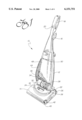
- FIG. 1 is a perspective view of an upright vacuum cleaner illustrating the present invention
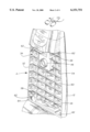
- FIG. 2 is a detailed perspective view showing the handle and canister assembly with the access door and the dust bag removed thereby exposing the access opening, the dust bag retaining cavity and the retention flaps for holding a dust bag within the cavity;
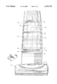
- FIG. 3 is a detailed front elevational view showing how the corners of the dust bag are received and held in the bag retention channels behind the retention flaps so that the dust bag does not interfere with reinstallation of the access door;
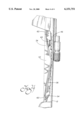
- FIG. 4 is a detailed side elevational view showing how the retention flaps function to engage the corners of a new bag to hold the bag fully within the bag cavity despite the presence of packaging folds and creases.
- FIG. 1 showing a perspective view of the upright vacuum cleaner 10 constructed in accordance with the teachings of the present invention.
- the overall basic design of an upright vacuum cleaner is generally well known in the art.
- the upright vacuum cleaner 10 includes a handle and canister assembly 12 that is pivotally connected to a nozzle assembly 14.
- a handle extension 16 is rigidly attached to the top of the handle and canister assembly 12.
- the handle extension 16 includes a hand grip 18 and a power switch 20 for turning the vacuum cleaner on and off. Of course, electrical power is supplied through a cord (not shown).
- rear wheels 22 are provided to support the weight of the vacuum cleaner 10 and provide a pivot point about which the nozzle assembly 14 pivots when the height of the nozzle assembly is adjusted by manipulation of the height adjustment control 24.
- the operation of the height adjustment control 24 and its cooperating mechanism is described in detail in U.S. Pat. No. 5,467,502 to Johnson et al., the full disclosure of which is incorporated herein by reference.
- a foot latch 26 locks the handle and canister assembly 12 in an upright position as shown in FIG. 1 in order to allow storage and off the floor cleaning. When the foot latch 26 is released, the handle and canister assembly 12 may be pivoted relative to the nozzle assembly 14 in a manner well known in the art to allow manipulation of the vacuum cleaner during the cleaning operation.
- the handle and canister assembly 12 includes an internal chamber 32 which holds a motor 28 that drives a fan 30 which in turn generates a negative pressure or vacuum.
- the motor and fan assembly chamber 32 is provided in fluid communication by means of the opening (not shown) covered by filter 35 with a cavity 34 which receives and holds a dust bag 36.
- the motor 30 and fan 32 cooperate to draw dust and dirt laden air into the cavity 34 and through the porous walls of the dust bag 36.
- the dust bag 36 serves to trap suspended dirt and particles inside while allowing air to pass freely through for exhausting from the exhaust port 38.
- the nozzle assembly 14 includes, at its front portion, a nozzle 40 that houses a rotating agitator brush 42.
- the agitator brush 42 is rotatively driven by the motor 30 through a drive transmission (not shown). As the agitator brush 42 is rotated, the brush functions to loosen trapped dirt and particulate matter in a carpeted floor surface.
- the negative pressure or vacuum suction created by the motor 30 and fan 32 then draw the air laden with this dirt and particulate matter from the nozzle 40 through the nozzle assembly 14, the hose 44 and the conduit 46 (see FIGS. 1 and 2).
- the inlet opening of the dust bag 36 is secured over the end of the conduit 46 and, accordingly, the air laden with dirt and particulate matter enters the dust bag. There, the dirt and particulate matter is trapped in the dust bag 36 in the manner described above and well known in the art.
- the handle and canister assembly 12 also includes an access door 48 which may be removed by operation of the latch 50 in order to expose the cavity 34. More specifically, the handle and canister assembly 12 includes two sidewalls 52, 54, a top wall 56, a bottom wall 58 and a backwall 60. A corner is formed at the intersection of each sidewall 52, 54 with each top wall 56 and bottom wall 58. A triangular retention flap 62 is provided across each corner. Thus, an access opening A is defined by the sidewalls 52, 54, the top wall 56, the bottom wall 58 and the retention flaps 62. This access opening A allows one to install a dust bag 36 in the cavity 34 of the handle and canister assembly 12.
- each bag retention channel has a volume of at least 19,000 mm 3 and more preferably, a volume of between substantially 18,000-20,000 mm 3 in order to insure the necessary space to positively retain the corners of the dust bag 36 therein.
- the access opening defined between the sidewalls 52, 54, top wall 56, bottom wall 58 and retention flaps 62 preferably has an area of at least 72,000 mm 2 to provide sufficient clearance to allow one to conveniently manipulate the opening of the dust bag 36 over the conduit 46 and position the dust bag in the cavity 34 with the corners held in the dust bag retention channels 64.
- the retention flaps 62 engage and fully retain the bag in the cavity 34 behind the access opening defined by the outer exposed edges of the sidewalls 52, 54, the top wall 56 and the bottom wall 58 (see FIGS. 2 and 3). Accordingly, the dust bag 36 does not interfere with the installation of the access door 48. Accordingly, that door 48 may be easily replaced and latched in position to seal the dust bag 36 in the cavity 34 in the handle and canister assembly 12. Any potential for any portion of the dust bag 36 to be pinched or caught between the access door 48 and the sidewalls 52, 54, top wall 56 or bottom wall 58 in the handle canister assembly 12 is virtually eliminated. Accordingly, proper vacuum cleaner operation to the full capacity of the dust bag 36 is virtually assured. Further, proper seating of the access door 48 is virtually insured so that the cavity 34 is properly sealed. This prevents inadvertent pressure loss thereby insuring maximum cleaning efficiency.
- retention flaps 62 are provided across the corners of the access opening defined by the sidewalls 52, 54 at their intersection with the top and bottom walls 56, 58.
- the retention flaps 62 may be molded from plastic as an integral portion of the handle and canister assembly. These retention flaps 62 function with the adjacent walls to define bag retention channels 64 that serve to hold the dust bag 36 in the desired position fully within the cavity 34 to allow interference free placement of the access door 48.
Landscapes
- Engineering & Computer Science (AREA)
- Mechanical Engineering (AREA)
- Filters For Electric Vacuum Cleaners (AREA)
Abstract
Description
Claims (8)
Priority Applications (1)
| Application Number | Priority Date | Filing Date | Title |
|---|---|---|---|
| US09/297,806 US6151751A (en) | 1998-07-22 | 1998-07-22 | Vacuum cleaner with dust bag retention flaps |
Applications Claiming Priority (2)
| Application Number | Priority Date | Filing Date | Title |
|---|---|---|---|
| US09/297,806 US6151751A (en) | 1998-07-22 | 1998-07-22 | Vacuum cleaner with dust bag retention flaps |
| PCT/US1998/015186 WO2000004813A1 (en) | 1998-07-22 | 1998-07-22 | Vacuum cleaner with dust bag retention flaps |
Publications (1)
| Publication Number | Publication Date |
|---|---|
| US6151751A true US6151751A (en) | 2000-11-28 |
Family
ID=23147826
Family Applications (1)
| Application Number | Title | Priority Date | Filing Date |
|---|---|---|---|
| US09/297,806 Expired - Lifetime US6151751A (en) | 1998-07-22 | 1998-07-22 | Vacuum cleaner with dust bag retention flaps |
Country Status (1)
| Country | Link |
|---|---|
| US (1) | US6151751A (en) |
Cited By (8)
| Publication number | Priority date | Publication date | Assignee | Title |
|---|---|---|---|---|
| US6609270B2 (en) * | 2000-01-17 | 2003-08-26 | Samsung Kwangju Electronics Co., Ltd. | Discharge grill mounting structure of upright vacuum cleaner |
| USD497042S1 (en) | 2003-07-31 | 2004-10-05 | Matsushita Electric Corporation Of America | Bagless upright vacuum cleaner |
| USD522194S1 (en) * | 2004-05-13 | 2006-05-30 | Dyson Limited | Filter arrangement for a vacuum cleaner |
| US20070022565A1 (en) * | 2005-07-28 | 2007-02-01 | Panasonic Corporation Of North America | Vacuum cleaner equipped with bag compartment including a bag cage |
| US20070289088A1 (en) * | 2006-06-15 | 2007-12-20 | Mayes R Michael | Bag cage having bag caddy |
| USD559483S1 (en) | 2006-01-25 | 2008-01-08 | Johnsondiversey, Inc. | Vacuum bag attachment |
| USD664317S1 (en) | 2011-08-16 | 2012-07-24 | Nss Enterprises, Inc. | Top plate for a filter bag |
| US8439997B2 (en) | 2011-08-16 | 2013-05-14 | Nss Enterprises, Inc. | Vacuum sweeper apparatus including a filter bag and a method of installation |
Citations (16)
| Publication number | Priority date | Publication date | Assignee | Title |
|---|---|---|---|---|
| US2779432A (en) * | 1953-05-07 | 1957-01-29 | Lewyt Corp | Vacuum cleaner assembly |
| US3238706A (en) * | 1962-08-14 | 1966-03-08 | Hoover Co | Suction cleaners |
| US3634905A (en) * | 1969-10-27 | 1972-01-18 | Gen Electric | Electric vacuum cleaner construction |
| US3763635A (en) * | 1971-09-30 | 1973-10-09 | Whirlpool Co | Vacuum cleaner construction |
| US4193844A (en) * | 1975-10-07 | 1980-03-18 | Delbag-Luftfilter Gmbh | Method of mounting filter elements and mounting therefor |
| US4257789A (en) * | 1978-06-12 | 1981-03-24 | Aktiebolaget Electrolux | Combination vacuum cleaner and dust container |
| US4512057A (en) * | 1984-04-30 | 1985-04-23 | The Singer Company | Floor care appliance |
| US4670937A (en) * | 1986-05-30 | 1987-06-09 | The Singer Company | Filter retention system for vacuum cleaners |
| US4705547A (en) * | 1986-09-29 | 1987-11-10 | The Singer Company | Dirt drawer latch for vacuum cleaner |
| US4738697A (en) * | 1986-12-09 | 1988-04-19 | Whirlpool Corporation | Vacuum cleaner bag mount and method for mounting a dust bag thereon |
| US4745654A (en) * | 1985-08-08 | 1988-05-24 | Sanyo Electric Co., Ltd. | Hand-held vacuum cleaner |
| EP0322387A2 (en) * | 1987-12-21 | 1989-06-28 | Aktiebolaget Electrolux | Vacuum cleaner |
| US4885013A (en) * | 1987-05-04 | 1989-12-05 | Vorwerk & Co. Interholding Gmbh | Arrangement of filter bags in electric vacuum cleaners |
| US5390392A (en) * | 1993-05-17 | 1995-02-21 | White Consolidated Industries, Inc. | Vacuum cleaner bag cover with enlarged access opening |
| US5755009A (en) * | 1996-01-16 | 1998-05-26 | Royal Appliance Mfg. Co. | Bag mount for a vacuum cleaner |
| US5961676A (en) * | 1997-06-09 | 1999-10-05 | The Hoover Company | Hard bag door with air directing arrangement |
-
1998
- 1998-07-22 US US09/297,806 patent/US6151751A/en not_active Expired - Lifetime
Patent Citations (16)
| Publication number | Priority date | Publication date | Assignee | Title |
|---|---|---|---|---|
| US2779432A (en) * | 1953-05-07 | 1957-01-29 | Lewyt Corp | Vacuum cleaner assembly |
| US3238706A (en) * | 1962-08-14 | 1966-03-08 | Hoover Co | Suction cleaners |
| US3634905A (en) * | 1969-10-27 | 1972-01-18 | Gen Electric | Electric vacuum cleaner construction |
| US3763635A (en) * | 1971-09-30 | 1973-10-09 | Whirlpool Co | Vacuum cleaner construction |
| US4193844A (en) * | 1975-10-07 | 1980-03-18 | Delbag-Luftfilter Gmbh | Method of mounting filter elements and mounting therefor |
| US4257789A (en) * | 1978-06-12 | 1981-03-24 | Aktiebolaget Electrolux | Combination vacuum cleaner and dust container |
| US4512057A (en) * | 1984-04-30 | 1985-04-23 | The Singer Company | Floor care appliance |
| US4745654A (en) * | 1985-08-08 | 1988-05-24 | Sanyo Electric Co., Ltd. | Hand-held vacuum cleaner |
| US4670937A (en) * | 1986-05-30 | 1987-06-09 | The Singer Company | Filter retention system for vacuum cleaners |
| US4705547A (en) * | 1986-09-29 | 1987-11-10 | The Singer Company | Dirt drawer latch for vacuum cleaner |
| US4738697A (en) * | 1986-12-09 | 1988-04-19 | Whirlpool Corporation | Vacuum cleaner bag mount and method for mounting a dust bag thereon |
| US4885013A (en) * | 1987-05-04 | 1989-12-05 | Vorwerk & Co. Interholding Gmbh | Arrangement of filter bags in electric vacuum cleaners |
| EP0322387A2 (en) * | 1987-12-21 | 1989-06-28 | Aktiebolaget Electrolux | Vacuum cleaner |
| US5390392A (en) * | 1993-05-17 | 1995-02-21 | White Consolidated Industries, Inc. | Vacuum cleaner bag cover with enlarged access opening |
| US5755009A (en) * | 1996-01-16 | 1998-05-26 | Royal Appliance Mfg. Co. | Bag mount for a vacuum cleaner |
| US5961676A (en) * | 1997-06-09 | 1999-10-05 | The Hoover Company | Hard bag door with air directing arrangement |
Cited By (12)
| Publication number | Priority date | Publication date | Assignee | Title |
|---|---|---|---|---|
| US6609270B2 (en) * | 2000-01-17 | 2003-08-26 | Samsung Kwangju Electronics Co., Ltd. | Discharge grill mounting structure of upright vacuum cleaner |
| USD497042S1 (en) | 2003-07-31 | 2004-10-05 | Matsushita Electric Corporation Of America | Bagless upright vacuum cleaner |
| USD522194S1 (en) * | 2004-05-13 | 2006-05-30 | Dyson Limited | Filter arrangement for a vacuum cleaner |
| US20070022565A1 (en) * | 2005-07-28 | 2007-02-01 | Panasonic Corporation Of North America | Vacuum cleaner equipped with bag compartment including a bag cage |
| US7676884B2 (en) | 2005-07-28 | 2010-03-16 | Panasonic Corporation Of North America | Vacuum cleaner equipped with bag compartment including a bag cage |
| USD559483S1 (en) | 2006-01-25 | 2008-01-08 | Johnsondiversey, Inc. | Vacuum bag attachment |
| US20070289088A1 (en) * | 2006-06-15 | 2007-12-20 | Mayes R Michael | Bag cage having bag caddy |
| US20090265881A1 (en) * | 2006-06-15 | 2009-10-29 | Mayes R Michael | Bag cage having bag caddy |
| US7735187B2 (en) | 2006-06-15 | 2010-06-15 | Panasonic Corporation Of North America | Bag cage having bag caddy |
| US7752707B2 (en) * | 2006-06-15 | 2010-07-13 | Panasonic Corporation Of North America | Bag cage having bag candy |
| USD664317S1 (en) | 2011-08-16 | 2012-07-24 | Nss Enterprises, Inc. | Top plate for a filter bag |
| US8439997B2 (en) | 2011-08-16 | 2013-05-14 | Nss Enterprises, Inc. | Vacuum sweeper apparatus including a filter bag and a method of installation |
Similar Documents
| Publication | Publication Date | Title |
|---|---|---|
| US5867863A (en) | Dust bag housing door with final filtration compartment | |
| CA2445242C (en) | Vacuum cleaner equipped with dirt cup and separate filter drawer | |
| US6807708B2 (en) | Upright vacuum cleaner with dual hoses and hose ports | |
| US7134165B2 (en) | Bagless vacuum cleaner system | |
| US20090293222A1 (en) | Motor enclosure for a vacuum cleaner | |
| CN102238892B (en) | Vacuum cleaner bag docking assembly | |
| CA2448457C (en) | Removable dirt cup assembly with external filter | |
| US7343643B2 (en) | Selective bag or bagless cleaning system | |
| CA2448414C (en) | Dirt cup assembly with attachable and detachable external filter holder | |
| CA2591831C (en) | Bag cage having bag caddy | |
| US6151751A (en) | Vacuum cleaner with dust bag retention flaps | |
| US7260867B2 (en) | Bagless dust box for vacuum cleaner | |
| US6421874B1 (en) | Pivotal edge cleaning brushes for vacuum cleaner | |
| CA2273104C (en) | Vacuum cleaner with dust bag retention flaps | |
| CA2552302C (en) | Vaccum cleaner equipped with bag compartment including a bag cage | |
| CA2463270C (en) | Agitator cavity fitting for floor care cleaning apparatus | |
| CA2464577C (en) | Holder for alternately receiving wand or cleaning tool | |
| CA2448411C (en) | Bagless vacuum cleaner with removable dirt cup | |
| US11786089B2 (en) | Vacuum cleaner including hose retainer with dustpan and method of assembling same | |
| CA2547048C (en) | Floor cleaning apparatus equipped with removable half-plenum | |
| KR20040080085A (en) | A tray assembly for vacuum cleaner | |
| JP2000189351A (en) | Electric vacuum cleaner |
Legal Events
| Date | Code | Title | Description |
|---|---|---|---|
| AS | Assignment |
Owner name: MATSUSHITA HOME APPLIANCE CORPORATION OF AMERICA, Free format text: ASSIGNMENT OF ASSIGNORS INTEREST;ASSIGNORS:SCHIMIZU, YUICHI;MCCORMICK, MICHAEL J.;REEL/FRAME:010068/0771 Effective date: 19990408 Owner name: MATSUSHITA HOME APPLIANCE CORPORATION OF AMERICA, Free format text: ASSIGNMENT OF ASSIGNORS INTEREST;ASSIGNORS:SCHIMIZU, YUICHI;MCCORMICK, MICHAEL J.;REEL/FRAME:010673/0029 Effective date: 19990408 |
|
| AS | Assignment |
Owner name: MATSUSHITA ELECTRIC CORPORATION OF AMERICA, KENTUC Free format text: ASSIGNMENT OF ASSIGNORS INTEREST;ASSIGNOR:MATSUSHITA HOME APPLIANCE CORPORATION OF AMERICA;REEL/FRAME:010226/0468 Effective date: 19990902 |
|
| AS | Assignment |
Owner name: MATSUSHITA ELECTRIC CORPORATION OF AMERICA, NEW JE Free format text: MERGER;ASSIGNOR:MATSUSHITA HOME APPLIANCE CORPORATION OF AMERICA;REEL/FRAME:010272/0764 Effective date: 19990831 |
|
| STCF | Information on status: patent grant |
Free format text: PATENTED CASE |
|
| FPAY | Fee payment |
Year of fee payment: 4 |
|
| AS | Assignment |
Owner name: PANASONIC CORPORATION OF NORTH AMERICA, NEW JERSEY Free format text: CHANGE OF NAME;ASSIGNOR:MATSUSHITA ELECTRIC CORPORATION OF AMERICA;REEL/FRAME:015972/0688 Effective date: 20041101 |
|
| FPAY | Fee payment |
Year of fee payment: 8 |
|
| FPAY | Fee payment |
Year of fee payment: 12 |