US6151437A - Junction enclosure for fiber optic telemetry system - Google Patents
Junction enclosure for fiber optic telemetry system Download PDFInfo
- Publication number
- US6151437A US6151437A US09/059,023 US5902398A US6151437A US 6151437 A US6151437 A US 6151437A US 5902398 A US5902398 A US 5902398A US 6151437 A US6151437 A US 6151437A
- Authority
- US
- United States
- Prior art keywords
- box
- telemetry system
- fiber optic
- fiber
- fibers
- Prior art date
- Legal status (The legal status is an assumption and is not a legal conclusion. Google has not performed a legal analysis and makes no representation as to the accuracy of the status listed.)
- Expired - Lifetime
Links
Images

Classifications
-
- G—PHYSICS
- G02—OPTICS
- G02B—OPTICAL ELEMENTS, SYSTEMS OR APPARATUS
- G02B6/00—Light guides; Structural details of arrangements comprising light guides and other optical elements, e.g. couplings
- G02B6/44—Mechanical structures for providing tensile strength and external protection for fibres, e.g. optical transmission cables
- G02B6/4439—Auxiliary devices
- G02B6/4471—Terminating devices ; Cable clamps
Definitions
- the present invention relates to cabled fiber optic telemetry systems. More particularly, this invention pertains to a junction for facilitating the routing and protection of the optical fibers for carrying input and return signals in such systems between downstream (or remote) sensors and an upstream (or home) source and detectors.
- Fiber optic telemetry systems are routinely employed in configurations wherein multiple remote (“downstream”) sensors, such as hydrophones, communicate with an on-board or home (“upstream”) light source and detectors.
- the telemetry required to monitor vast arrays of downstream sensors may involve a multiplicity of light transmission routes (via dedicated optical fibers) between the downstream sensors and the upstream source and detectors.
- an input and a return path comprising optical fiber associated with each sensor includes a downstream cable(s) within which both are gathered for any particular sensor. Such gathering of fibers that communicate with various sensors provides both shielding and mechanical durability.
- optical fiber in systems of the above type can pose considerable problems.
- Each individual fiber possesses substantially no rigidity and is therefore subject to tangling.
- many splices may be required within such a system due, for example, to incompatibilities (in terms of fiber-carrying capacities) between, for example, the optical cabling of a home ship and a remote sensor array.
- the present invention addresses the foregoing and other problems of the prior art by providing, in a first aspect, a junction for a fiber optic telemetry system.
- At least one closed box is located intermediate the upstream and downstream ends of the system.
- Such box has at least one internal cavity.
- the box comprises multiple, longitudinally-matching elements that include straight facing edges. Indentations within such edges define a plurality of apertures within the upstream and downstream walls of the box.
- the present invention provides an improvement in a fiber optic telemetry system of the type wherein the output of a light source is input to a cable that includes at least one optical fiber, then split by at least one coupler and applied to a plurality of fibers, each being the input fiber of at least one remote sensor.
- a return fiber is also associated with the sensor. The input and return fiber are gathered within at least one cable.
- At least one optical detector is provided for receiving optical output signals transmitted through the return fibers.
- the improvement provided by the invention includes at least one routing box for receiving the cable.
- the routing box includes means for separating the input fibers from return fibers.
- a splice box is provided for housing at least one coupler. The boxes are longitudinally-displaced with respect to one another. Means are provided for housing the fibers. Such means are arranged to direct at least one input fiber from a routing box to the splice protection box and to direct at least one return fiber to the detectors.
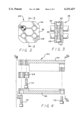
- FIG. 1 is a schematic representation of a telemetry junction in accordance with the invention
- FIG. 2 is a sectional view taken at line 2--2 of FIG. 1 for illustrating a representative clamp of the invention
- FIG. 3 is a sectional view taken at line 3--3 of FIG. 2 for illustrating the manner in which the clamp is secured to hold the cables of optical fiber;
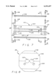
- FIG. 4 is an exploded side elevation view of a fiber routing box
- FIGS. 5(a) and 5(b) are downstream and upstream elevation views, respectively, of the end walls of a routing box;
- FIG. 6 is a top plan view, partly in section, of a fiber routing box for illustrating the manner of fixation of a fiber enclosure tube;
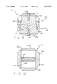
- FIG. 7 is an exploded side sectional view of a splice/coupler protection box
- FIG. 8 is an end elevation view of a splice/coupler protection box taken generally on line 8--8 of FIG. 7;
- FIG. 9 is a cross-sectional view taken on line 9--9 of FIG. 7;
- FIG. 10 is a sectional view taken on line 10--10 of FIG. 7.
- FIG. 1 is a schematic representation of a telemetry junction 10 in accordance with the invention.
- the junction 10 supports the necessary fiber couplings between an upstream light source 12 and detectors 18 with downstream optical sensors (not shown).
- downstream-generated sensor outputs and inputs communicate through sets of cables 14, 16 with each individual cable of the sets 14 and i6 assumed to carry a multiplicity of input path and return path fibers.
- the sets of cables 14, 16 are received by fiber routing boxes 20 and 22.
- the locations of the routing boxes 20, 22 are staggered with respect to one another to provide installation compactness for passage through small apertures or ports.
- a splice protection box 28 is optionally provided should, as is often the case, optical splices be required to insert couplers into the input fiber network of the telemetry system. It will be appreciated from the discussion that follows that the boxes 20 and 22 may provide alternate locations for the sheltering of splices.
- Optical fibers from the connector 30 are enclosed within a metallic fiber enclosure tube 32, preferably of stainless steel or aluminum, fixed, at one end, to the connector 30 and, at the opposed end, to the splice protection box 28.
- the splice protection box 28 provides a convenient location within the telemetry system to house the couplers spliced onto the input path optical fibers that receive the output of the light source 12 and thereby multiply the number of input fibers as one proceeds downstream from the source 12.
- the input path-dedicated optical fibers are directed to the fiber routing boxes 20 and 22 by metallic fiber enclosure tubes 34 and 36 respectively.
- pairs of detector enclosure tubes 38, 40 and 42, 44 are provided for housing the return-path dedicated optical fibers (not shown) that bring output signals from the downstream optical sensors.
- the tubes 38, 40, 42 and 44 terminate, at their remote ends, in optical connectors 46, 48, 50 and 52 respectively for engaging similar connectors of optical cables (not shown) engaged to the detectors 18.
- the connectors 46 through 52 may be of the type disclosed in U.S. Pat. No. 5,590,229.
- FIG. 2 is a sectional view taken at line 2--2 of FIG. 1 for illustrating the arrangement of the representative clamp 26.
- the clamp 26 comprises three members 54, 56 and 58.
- the members 54 and 58 include rounded edges to avoid damage, for example, to unrelated cabling should the fiber optic telemetry system be harnessed to other cabling.
- Each of such members includes at least one straight internal edge having semicircular indentations either machined or punched therein.
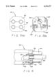
- FIG. 3 a sectional view taken at line 3--3 of FIG. 2, illustrates the manner in which the clamp is secured to hold the cables of optical fiber.
- countersunk screws 60 and 62 separately connect the members 54 and 56 to one another and the members 58 to 56 to one another along predetermined facing straight edges to thereby form the above-described circular apertures.
- one's ability to handle or manage the multiple cables 16 for inputting to the box 22, especially in tight quarters is facilitated. That is, one can first secure, for example, the upper pair of cables by arranging the members 54 and 56 about that pair of cables, ignoring the others while and securing that engagement by inserting and tightening the screw 60. Thereafter, the lower pair may be similarly secured, without concern for the upper pair of cables, by aligning the member 58 with the member 56 as shown in FIG. 2, then tightening the hex cap screw 62.
- the ability to simplify processes by cutting task complexity at least in half greatly reduces the human effort required when working in close quarters. As a result, personnel are considerably less likely to make critical mistakes.
- FIG. 4 is an exploded side elevation view of a fiber routing box 63 (identical to either of the boxes 20 or 22 of FIG. 1).
- the fiber routing box 63 serves as the location within the junction 10 for separation of the return path-directed fibers from the input path-dedicated fibers commingled with one another within the cables 14 or 16. Conversely, looking downstream, they can be considered as the gathering locations for fibers from the detectors 18 and the light source 12 into downstream sensor-directed cables.
- the downstream end wall is formed of three members 64, 66 and 68, each having a straight edge with semicircular recesses on mutually-facing edges for forming circular apertures to accommodate the optical cables.
- two of such pieces may be joined independently of the third, again allowing one to work on two of the four cables at a time.
- the members 64 and 68 may first be secured to clamp two optical cables at the top half of the box 63 by means of a screw 70.
- the outer jackets of the two cables are stripped so that input fibers can be separated from return fibers, then routed. Thereafter, the remaining pair of optical cables may then be clamped, stripped, routed and the somewhat-longer screw 72 (and a screw 78) tightened to close the box 63. As in the case of the clamps, such arrangement insures ready manageability of the four cables.
- the return fibers of the cables after sorting within the box 63, can pass through square apertures 74, 76 within the upstream wall formed by matching indentations in facing edges of the members 64 and 66.
- a circular aperture 80 is provided for routing input optical fibers.
- FIG. 6 is a top plan view, partly in section, of the fiber routing box 63 for illustrating the manner of fixation of a representative fiber enclosure tube 82.
- the discussion of such arrangement applies equally to all interfaces of boxes with metallic fiber enclosure tubes as shown in FIG. 1.
- a flange 84 is provided in abutment with the (in this case) upstream wall of the box 63.
- the tube 82 is fixed to the flange 84 by solder braze 86.
- the fiber enclosure tubes 82, 88 and 90, each soldered to the flange 84, are attached to the member 63, and thereby to the end of the fiber routing box 63, by means of screws, one of which is illustrated at 92. Referring back to FIG.
- FIG. 7 is an exploded side sectional view of the splice/coupler protection box 28.
- the box 28 provides an easily-assembled structure of multiple parts held together by means of counter-sunk screws.
- FIG. 7 in combination with FIG. 8 an end elevational view of the assembled splice/coupler protection box 28 taken generally on line 8--8 of FIG. 7 and FIG. 9, a cross-sectional view taken on line 9--9 of FIG. 7, one may again observe that a pair of circular apertures 102, 104 is provided in the downstream end wall of the box 28 upon the engagement of end wall members 106 and 108 of upper and lower shell elements 110 and 112 to one another.
- the shells 110, 112 constitute mirror images of one another.
- the upper shell 110 by way of explanation, it is seen to comprise a walled arrangement including opposed end walls 106 and 114 spaced from one another by means of a floor 116 that includes slotted end portions 118 and 120.
- Sidewalls, including the sidewall 122 are spaced from one another at either edge of the floor 116, giving the upper shell 110 (as well as the lower shell 112) an open box-type structure.
- FIG. 10 When assembled, the upper and lower shells 110, 112 abut one another as shown in FIG. 7 to provide an interior horizontal separation plane or partition observed most clearly in FIG. 10, a sectional view taken on line 10--10 of FIG. 7. As shown in FIG. 10, separate upper and lower chambers 122 and 124 respectively are thereby defined within the box 28.
- the back-to-back arrangement of the upper and lower shells is secured by means of countersunk screws 128, 130.
- Optical fibers within the upper and lower chambers 122 and 124 are exposed after passage through the medal tubes that communicate with the source 12 and the boxes 20 and 22. This permits one to-perform that necessary splicing of fibers and insertion of optical couplers for sharing the output of the light source 12 with all input optical-path fibers that feed the array of optical sensors downstream.
- a circular aperture 144 is created at the center of the upstream wall of the box 28 by the abutment of the end wall 114 of the upper shell 110 with an end wall 146.
- Such circular aperture permits passage of input optical path fibers (carried within the tube 32 that is soldered to the end flange 100), into the interior chambers of the box 28. Again, semicircular grooves formed in facing edges, this time of the end walls 114, 146 of the shells 110 and 112 respectively, contribute to the circular aperture 144.
- the partitioning of the interior of the box 28 into an upper chamber 122 and a lower chamber 124, in combination with the slots 118, 120, 148 and 150 at the edges of the floors 116 and 126 provide a means for separating, and thereby separately handling, one half of the fiber splicing at a time. This greatly simplifies the complexity of the process and minimizes opportunities for mismatching fibers as well as tangling and breaking. Furthermore, by providing a box enclosure for the splices, the additional processing and bulk of shrink wrapping or other splice protection processes is avoided.
- the incoming input path fibers enter through the aperture 144 into an opening of the wall-like partition created by the matching end slots 120 and 150. At this point, a portion of the fibers may be selectively routed above the floor 116 of the upper shell 110 while the remaining portion may be routed below the floor 126.
- appropriate splicings may be made separately to the set "above partition” and "below partition” fibers respectively with splices arranged and sorted adjacent the respective floors 116, 126. Thereafter, the resulting arrangements of fibers may be routed through either of the apertures 102 and 104 within the downstream endwall of the box 28 as shown in FIG. 8.
- the separate internal chambers provide an opportunity to route all fiber connections for subsequent passage through one of the apertures 102 or 104 into one of the two chambers 122 and 124 while the other fibers are routed to the other chamber. In this way, fibers needing repair, etc. may be readily and easily accessed.
- the present invention provides apparatus for facilitating the management of the numerous optical fibers of a multi-sensor fiber optic telemetry system.
- one may handle the necessary interconnections and routing required to assure optical communication between downstream sensors and an upstream light source and photodetectors with minimal risk to the integrity of the flimsy and somewhat-fragile optical fibers.
- the junction apparatus of the invention provides shielding of the optical fibers throughout to avoid environmental bias sources while providing individual elements that are readily-assembled and readily disassembled for troubleshooting, repair and the like.
Landscapes
- Physics & Mathematics (AREA)
- General Physics & Mathematics (AREA)
- Optics & Photonics (AREA)
- Light Guides In General And Applications Therefor (AREA)
Abstract
Description
Claims (14)
Priority Applications (1)
| Application Number | Priority Date | Filing Date | Title |
|---|---|---|---|
| US09/059,023 US6151437A (en) | 1998-04-13 | 1998-04-13 | Junction enclosure for fiber optic telemetry system |
Applications Claiming Priority (1)
| Application Number | Priority Date | Filing Date | Title |
|---|---|---|---|
| US09/059,023 US6151437A (en) | 1998-04-13 | 1998-04-13 | Junction enclosure for fiber optic telemetry system |
Publications (1)
| Publication Number | Publication Date |
|---|---|
| US6151437A true US6151437A (en) | 2000-11-21 |
Family
ID=22020322
Family Applications (1)
| Application Number | Title | Priority Date | Filing Date |
|---|---|---|---|
| US09/059,023 Expired - Lifetime US6151437A (en) | 1998-04-13 | 1998-04-13 | Junction enclosure for fiber optic telemetry system |
Country Status (1)
| Country | Link |
|---|---|
| US (1) | US6151437A (en) |
Cited By (7)
| Publication number | Priority date | Publication date | Assignee | Title |
|---|---|---|---|---|
| US6269214B1 (en) * | 1998-08-04 | 2001-07-31 | Pouyet, S.A. | Device for interconnecting optical fiber cables |
| US20030031419A1 (en) * | 2001-08-10 | 2003-02-13 | 3M Innovative Properties Company | Optical manifold |
| US20030031437A1 (en) * | 2001-08-10 | 2003-02-13 | 3M Innovative Properties Company | In-line shuffle modules utilizing three dimensional optical circuits |
| US20030167800A1 (en) * | 2002-03-11 | 2003-09-11 | Atkins Robert M. | Soot layer formation for solution doping of glass preforms |
| US20040067002A1 (en) * | 2002-10-06 | 2004-04-08 | Weatherford/Lamb, Inc. | Multiple component sensor mechanism |
| GB2396211A (en) * | 2002-10-06 | 2004-06-16 | Weatherford Lamb | Multiple component sensor mechanism |
| EP2256531A1 (en) * | 2009-05-29 | 2010-12-01 | Corning Cable Systems LLC | Fiber optic harnesses and assemblies facilitating use of a pre-connectorized fiber optic cable(s) with a fiber optic terminal |
Citations (4)
| Publication number | Priority date | Publication date | Assignee | Title |
|---|---|---|---|---|
| US4252407A (en) * | 1977-11-24 | 1981-02-24 | Compagnie Generale D'electricite S.A. | Fibre-to-fibre connector for multifibre optical fibre cables |
| US5146532A (en) * | 1990-11-20 | 1992-09-08 | Scientific-Atlanta, Inc. | Optical fiber retention device |
| US5771324A (en) * | 1996-05-03 | 1998-06-23 | Laser Power Corporation | Polarization-preserving fiber optic assembly |
| US5999683A (en) * | 1998-07-01 | 1999-12-07 | American Pipe & Plastics, Inc | Clip device for conduits containing optical fibers |
-
1998
- 1998-04-13 US US09/059,023 patent/US6151437A/en not_active Expired - Lifetime
Patent Citations (4)
| Publication number | Priority date | Publication date | Assignee | Title |
|---|---|---|---|---|
| US4252407A (en) * | 1977-11-24 | 1981-02-24 | Compagnie Generale D'electricite S.A. | Fibre-to-fibre connector for multifibre optical fibre cables |
| US5146532A (en) * | 1990-11-20 | 1992-09-08 | Scientific-Atlanta, Inc. | Optical fiber retention device |
| US5771324A (en) * | 1996-05-03 | 1998-06-23 | Laser Power Corporation | Polarization-preserving fiber optic assembly |
| US5999683A (en) * | 1998-07-01 | 1999-12-07 | American Pipe & Plastics, Inc | Clip device for conduits containing optical fibers |
Cited By (18)
| Publication number | Priority date | Publication date | Assignee | Title |
|---|---|---|---|---|
| US6269214B1 (en) * | 1998-08-04 | 2001-07-31 | Pouyet, S.A. | Device for interconnecting optical fiber cables |
| US6850684B2 (en) | 2001-08-10 | 2005-02-01 | 3M Innovative Properties Company | Three dimensional optical circuits |
| US20030031419A1 (en) * | 2001-08-10 | 2003-02-13 | 3M Innovative Properties Company | Optical manifold |
| US20030031437A1 (en) * | 2001-08-10 | 2003-02-13 | 3M Innovative Properties Company | In-line shuffle modules utilizing three dimensional optical circuits |
| US6549710B2 (en) | 2001-08-10 | 2003-04-15 | 3M Innovative Properties Company | Method of making a three dimensional optical circuit |
| US6556754B2 (en) | 2001-08-10 | 2003-04-29 | 3M Innovative Properties Company | Three dimensional optical circuit |
| US6655848B2 (en) | 2001-08-10 | 2003-12-02 | 3M Innovative Properties Company | Method of making an optical manifold |
| US7597483B2 (en) | 2001-08-10 | 2009-10-06 | 3M Innovative Properties Company | Optical manifold |
| US6832032B2 (en) | 2001-08-10 | 2004-12-14 | 3M Innovative Properties Company | In-line shuffle modules utilizing three dimensional optical circuits |
| US6847774B2 (en) | 2001-08-10 | 2005-01-25 | 3M Innovative Properties Company | Three dimensional optical circuits |
| US20030167800A1 (en) * | 2002-03-11 | 2003-09-11 | Atkins Robert M. | Soot layer formation for solution doping of glass preforms |
| GB2396211A (en) * | 2002-10-06 | 2004-06-16 | Weatherford Lamb | Multiple component sensor mechanism |
| US6888972B2 (en) | 2002-10-06 | 2005-05-03 | Weatherford/Lamb, Inc. | Multiple component sensor mechanism |
| GB2396211B (en) * | 2002-10-06 | 2006-02-22 | Weatherford Lamb | Multiple component sensor mechanism |
| US7369716B2 (en) | 2002-10-06 | 2008-05-06 | Weatherford/Lamb, Inc. | High pressure and high temperature acoustic sensor |
| US20040067002A1 (en) * | 2002-10-06 | 2004-04-08 | Weatherford/Lamb, Inc. | Multiple component sensor mechanism |
| EP2256531A1 (en) * | 2009-05-29 | 2010-12-01 | Corning Cable Systems LLC | Fiber optic harnesses and assemblies facilitating use of a pre-connectorized fiber optic cable(s) with a fiber optic terminal |
| US20100303431A1 (en) * | 2009-05-29 | 2010-12-02 | Cox Terry D | Fiber Optic Harnesses and Assemblies Facilitating Use of a Pre-Connectorized Fiber Optic Cable(s) with a Fiber Optic Terminal |
Similar Documents
| Publication | Publication Date | Title |
|---|---|---|
| US5975769A (en) | Universal fiber optic module system | |
| US5644671A (en) | Optical fiber spice case with cross connect feature | |
| EP0692102B1 (en) | Optical fibre organizer | |
| US6539160B2 (en) | Optical fiber splicing and connecting assembly with coupler cassette | |
| JP3819022B2 (en) | Fiber optic organizer | |
| US6832035B1 (en) | Optical fiber connection system | |
| US5717811A (en) | Optical fiber organizer | |
| CN106687841A (en) | Cable distribution system | |
| AU2016363767B2 (en) | Cable distribution system with fan out devices | |
| US5093886A (en) | Optical communication system | |
| US20080279506A1 (en) | Blown Optical Fibre Multi-Tube Terminal Connectors | |
| GB2367379A (en) | Fibre optic organiser mounted to a wall | |
| MX2011006071A (en) | Fiber opitic adapter plate and cassette. | |
| HU218817B (en) | Arrangement for detached splitting or connecting optical fibres | |
| US6151437A (en) | Junction enclosure for fiber optic telemetry system | |
| US20140044400A1 (en) | Fiber management frames having modular tray holder | |
| GB2165661A (en) | Optical fibre junction box | |
| US12353040B2 (en) | Adapter configured to permit a heat shrink splice holder portion of a fiber splice cassette to hold a mechanical crimp splice protector | |
| US20220120985A1 (en) | Improved cable grounding assemblies for telecommunications enclosures | |
| EP0182494B1 (en) | Optical communication system | |
| CA2171349A1 (en) | Optical fibre organizer | |
| US10591692B2 (en) | Optical distribution frames | |
| US20250052973A1 (en) | Multi-work area fiber module | |
| CN215867246U (en) | Optical cable fiber-dividing box | |
| RU202124U1 (en) | Optical splitter module housing |
Legal Events
| Date | Code | Title | Description |
|---|---|---|---|
| AS | Assignment |
Owner name: LITTON SYSTEMS, INC., CALIFORNIA Free format text: ASSIGNMENT OF ASSIGNORS INTEREST;ASSIGNORS:CHERBETTCHIAN, AGOP H.;ARAB-SADEGHABADI, AKBAR;REEL/FRAME:009116/0875 Effective date: 19980406 |
|
| STCF | Information on status: patent grant |
Free format text: PATENTED CASE |
|
| FEPP | Fee payment procedure |
Free format text: PAYOR NUMBER ASSIGNED (ORIGINAL EVENT CODE: ASPN); ENTITY STATUS OF PATENT OWNER: LARGE ENTITY |
|
| FPAY | Fee payment |
Year of fee payment: 4 |
|
| FEPP | Fee payment procedure |
Free format text: PAYER NUMBER DE-ASSIGNED (ORIGINAL EVENT CODE: RMPN); ENTITY STATUS OF PATENT OWNER: LARGE ENTITY Free format text: PAYOR NUMBER ASSIGNED (ORIGINAL EVENT CODE: ASPN); ENTITY STATUS OF PATENT OWNER: LARGE ENTITY |
|
| FPAY | Fee payment |
Year of fee payment: 8 |
|
| AS | Assignment |
Owner name: NORTHROP GRUMMAN SYSTEMS CORPORATION, CALIFORNIA Free format text: ASSIGNMENT OF ASSIGNORS INTEREST;ASSIGNOR:NORTHROP GRUMMAN CORPORATION;REEL/FRAME:025597/0505 Effective date: 20110104 |
|
| FPAY | Fee payment |
Year of fee payment: 12 |