US6151217A - Apparatus and method for enabling hot plugging of an integrated circuit - Google Patents
Apparatus and method for enabling hot plugging of an integrated circuit Download PDFInfo
- Publication number
- US6151217A US6151217A US09/260,281 US26028199A US6151217A US 6151217 A US6151217 A US 6151217A US 26028199 A US26028199 A US 26028199A US 6151217 A US6151217 A US 6151217A
- Authority
- US
- United States
- Prior art keywords
- component
- heatsink
- contact pins
- frame
- guide member
- Prior art date
- Legal status (The legal status is an assumption and is not a legal conclusion. Google has not performed a legal analysis and makes no representation as to the accuracy of the status listed.)
- Expired - Lifetime
Links
Images
Classifications
-
- H—ELECTRICITY
- H10—SEMICONDUCTOR DEVICES; ELECTRIC SOLID-STATE DEVICES NOT OTHERWISE PROVIDED FOR
- H10W—GENERIC PACKAGES, INTERCONNECTIONS, CONNECTORS OR OTHER CONSTRUCTIONAL DETAILS OF DEVICES COVERED BY CLASS H10
- H10W40/00—Arrangements for thermal protection or thermal control
- H10W40/40—Arrangements for thermal protection or thermal control involving heat exchange by flowing fluids
- H10W40/43—Arrangements for thermal protection or thermal control involving heat exchange by flowing fluids by flowing gases, e.g. forced air cooling
-
- H—ELECTRICITY
- H10—SEMICONDUCTOR DEVICES; ELECTRIC SOLID-STATE DEVICES NOT OTHERWISE PROVIDED FOR
- H10W—GENERIC PACKAGES, INTERCONNECTIONS, CONNECTORS OR OTHER CONSTRUCTIONAL DETAILS OF DEVICES COVERED BY CLASS H10
- H10W40/00—Arrangements for thermal protection or thermal control
- H10W40/20—Arrangements for cooling
- H10W40/22—Arrangements for cooling characterised by their shape, e.g. having conical or cylindrical projections
Definitions
- This invention relates in general to electrical components with pin contacts and in particular to a device and method for hot plugging an electrical component with pin contacts into a socket.
- modules with pin-in-hole (PIH) packaging typically have a module body with a plurality of straight, electrical contact pins extending from its lower surface.
- the pins can be bent or otherwise damaged by incidental contact or by mishandling by unskilled persons In such instances, the module is often permanently damaged and must be discarded. This source of waste can significantly increase manufacturing costs as the module typically represents a relatively expensive portion of the final product.
- Hot plugging refers to inserting the component into the socket either while the socket has power applied to it or while the system it is inserted into is operating. A simple, inexpensive device and/or method for hot plugging a component into a socket while protecting its contact pins is needed.
- An apparatus for handling an electrical component, such as a CPU module, having a heatsink mounted to an upper surface and a plurality of contact pins is disclosed.
- the apparatus has a base plate with a central opening, a pair of parallel end plates extending upward from the base plate, and a top plate with a pair of integral air baffles.
- a set of fasteners are used to mount and retain the component/heatsink assembly within the apparatus.
- the air baffles are used to deflect air flow through the heatsink.
- the apparatus also has a handle on the top plate and a guide post on each comer of the bottom plate for handling and pin protection.
- the component/heatsink assembly is mounted in the apparatus before the top plate is attached such that the pins of the component extend through the opening in the base plate.
- the fasteners secure the assembly from movement relative to the apparatus.
- the apparatus/component assembly is then mounted onto a mating socket by aligning the guide posts with holes in the socket. The assembly is pressed into the socket until the pins seat in the socket holes. The apparatus is left installed with the component.
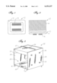
- FIG. 1 is a bottom view of an electrical component having pin contacts.
- FIG. 2 is a side view of a heatsink mounted on top of the component of FIG. 1.
- FIG. 3 is an isometric view of an apparatus constructed in accordance with the invention.
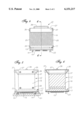
- FIG. 4 is a side view of the connector and heatsink assembly of FIG. 2 shown installed in the apparatus of FIG. 3.
- FIG. 5 is an end view of the component, heatsink and apparatus assembly of FIG. 4.
- FIG. 6 is a sectional end view of the component, heatsink and apparatus assembly of FIG. 4 taken along the line 6--6 of FIG. 4.
- an electrical component 11 such as a CPU module, has a generally rectangular module body 13 and a plurality of straight, electrical contact pins 15 extending from its lower surface.
- component 11 is shown with pin-in-hole (PIH) packaging, component 11 may be formed and sized in many different configurations.
- a conventional heatsink 17 (FIG. 2) having a plurality of flat, parallel fins 19 is mounted to an upper surface of component 11.
- an apparatus 21 having a generally cubic shape is provided for surrounding and protecting component 11 and heatsink 17.
- Apparatus 21 comprises a thin-walled frame having a large rectangular opening on each side.
- Apparatus 21 has a bottom support plate 23, a pair of upright, parallel end walls 25, and a top plate 27 which is parallel to bottom support plate 23. These elements may be formed from spring steel, sheet metal, plastic or other materials.
- Bottom support plate 23 has a large, central rectangular opening 31 for accommodating pins 15 of component 11.
- Each end wall 25 has a pair of a attachment screws 33 near its lower end, and a pair of air baffle screws 35 near its upper end. Each screw 33,35 is inserted through a threaded hole in one of end walls 25. As shown in FIGS.
- top plate 27 has an integral air deflection feature or baffle 37 at each end.
- Each air baffle 37 has a downward inclined cross-section for de-Recting air flow toward and into heatsink 17.
- the lower edges of air baffles 37 engage fins 19 near their upper ends and along their outer surfaces to secure the connector/heatsink assembly within apparatus 21.
- Apparatus 21 also has a handle 39 mounted to the upper surface of top plate 27.
- a guide post 41 extends from the lower surface of each corner of bottom plate 23. Guide posts 41 are short, cylindrical members with pointed ends. Note that guide posts 41 extend from bottom plate 23 for a distance which is greater than the distance that pins 15 extend beneath bottom plate 23.
- the component a heatsink assembly FIG. 2 In operation (FIGS. 4-6), the component a heatsink assembly FIG. 2) is loaded into apparatus 21 before top plate 27 is attached. As the component/heatsink assembly is placed in apparatus 21, the pins 15 of component 11 are carefully extended through central opening 31 without contact. As shown in FIG. 4, the side edges of body 13 abut the inner surfaces of end walls 25 to ensure proper alignment of pins 15 relative to guide posts 41. Top plate 27 is placed on top of heatsink 17 and apparatus 21 so that air baffles 37 closely abut their outer edges (FIG. 6). When the component/heatsink assembly is aligned, the four screws 33 are tightened to secure the assembly from movement relative to apparatus 21. The four screws 35 are then tightened against end walls 36 to secure top plate 27 and the upper end of heatsink 17 from movement relative to apparatus 21.
- the assembly of component 11 and apparatus 21 is now ready to be mounted onto an electrical receptacle FIG. 5) such as printed circuit board 51 or a mating socket 53 on PCB 51.
- the assembly may be hot plugged while the system is running by inserting component 11 into the receptacle. If the receptacle is socket 53, socket 53 will not have power applied to it during this time.
- the pointed tips of guide posts 41 are placed in alignment holes 55 in an upper surface of socket 53. Guide posts 41 touch and align with holes 55 before pins 15 come into contact with the pinholes in socket 53.
- the assembly of apparatus 21 and component 11 is pressed into socket 53 until pins 15 seat in the pinholes in socket 53 and PCB 51.
- bottom plate 23 abuts the upper surface of socket 53 and apparatus 21 will be left permanently installed with component 11.
- End walls 25 are parallel to the fins 19 of heatsink 17 and air baffles 37 direct airflow through apparatus 21 and fins 19 of heatsink 17.
- the invention has several advantages. This simple, inexpensive device allows hot plugging of modules while the associated system is running. The device is easy to handle and provides room for the modules heatsink. The device also has an integrated air baffle and allows unskilled persons to install even expensive components with less likelihood of damaging the component.
Landscapes
- Electric Connection Of Electric Components To Printed Circuits (AREA)
Abstract
Description
Claims (17)
Priority Applications (1)
| Application Number | Priority Date | Filing Date | Title |
|---|---|---|---|
| US09/260,281 US6151217A (en) | 1999-03-02 | 1999-03-02 | Apparatus and method for enabling hot plugging of an integrated circuit |
Applications Claiming Priority (1)
| Application Number | Priority Date | Filing Date | Title |
|---|---|---|---|
| US09/260,281 US6151217A (en) | 1999-03-02 | 1999-03-02 | Apparatus and method for enabling hot plugging of an integrated circuit |
Publications (1)
| Publication Number | Publication Date |
|---|---|
| US6151217A true US6151217A (en) | 2000-11-21 |
Family
ID=22988538
Family Applications (1)
| Application Number | Title | Priority Date | Filing Date |
|---|---|---|---|
| US09/260,281 Expired - Lifetime US6151217A (en) | 1999-03-02 | 1999-03-02 | Apparatus and method for enabling hot plugging of an integrated circuit |
Country Status (1)
| Country | Link |
|---|---|
| US (1) | US6151217A (en) |
Cited By (7)
| Publication number | Priority date | Publication date | Assignee | Title |
|---|---|---|---|---|
| US6374906B1 (en) * | 2000-04-11 | 2002-04-23 | Hewlett-Packard Company | Heat sink having a captive handle |
| US20030117777A1 (en) * | 2001-12-26 | 2003-06-26 | Franz John P. | Blindmate heat sink assembly |
| US20030168208A1 (en) * | 2002-03-11 | 2003-09-11 | Kaoru Sato | Electronic component cooling apparatus |
| US20030235034A1 (en) * | 2002-06-25 | 2003-12-25 | Compaq Information Technologies Group, L.P. | Component alignment and retention mechanism |
| US6687126B2 (en) * | 2001-04-30 | 2004-02-03 | Hewlett-Packard Development Company, L.P. | Cooling plate arrangement for electronic components |
| US20070209781A1 (en) * | 2006-03-10 | 2007-09-13 | Qnx Cooling Systems Inc. | Heat exchanger easy mount system |
| US20250239503A1 (en) * | 2024-01-18 | 2025-07-24 | ZT Group Int’l, Inc. dba ZT Systems | Heat sink with heat pipe handle portion |
Citations (8)
| Publication number | Priority date | Publication date | Assignee | Title |
|---|---|---|---|---|
| US5241453A (en) * | 1991-11-18 | 1993-08-31 | The Whitaker Corporation | EMI shielding device |
| US5313701A (en) * | 1990-04-14 | 1994-05-24 | Robert Bosch Gmbh | Assembly and testing of electronic power components insulation |
| US5475261A (en) * | 1990-09-19 | 1995-12-12 | Fujitsu Limited | Semiconductor device having many lead pins |
| US5477916A (en) * | 1995-02-27 | 1995-12-26 | Lin; Shih-Jen | Retainer frame assembly for dissipating heat generated on an integrated circuit chip |
| US5761041A (en) * | 1996-06-25 | 1998-06-02 | Sun Microsystems, Inc. | Mechanical heat sink attachment |
| US5815371A (en) * | 1996-09-26 | 1998-09-29 | Dell U.S.A., L.P. | Multi-function heat dissipator |
| US5946191A (en) * | 1997-03-27 | 1999-08-31 | Nec Corporation | Electronic device having a plug-in unit with a heat sink structure |
| US5966289A (en) * | 1998-08-31 | 1999-10-12 | Compaq Computer Corporation | Electronic device securement system |
-
1999
- 1999-03-02 US US09/260,281 patent/US6151217A/en not_active Expired - Lifetime
Patent Citations (8)
| Publication number | Priority date | Publication date | Assignee | Title |
|---|---|---|---|---|
| US5313701A (en) * | 1990-04-14 | 1994-05-24 | Robert Bosch Gmbh | Assembly and testing of electronic power components insulation |
| US5475261A (en) * | 1990-09-19 | 1995-12-12 | Fujitsu Limited | Semiconductor device having many lead pins |
| US5241453A (en) * | 1991-11-18 | 1993-08-31 | The Whitaker Corporation | EMI shielding device |
| US5477916A (en) * | 1995-02-27 | 1995-12-26 | Lin; Shih-Jen | Retainer frame assembly for dissipating heat generated on an integrated circuit chip |
| US5761041A (en) * | 1996-06-25 | 1998-06-02 | Sun Microsystems, Inc. | Mechanical heat sink attachment |
| US5815371A (en) * | 1996-09-26 | 1998-09-29 | Dell U.S.A., L.P. | Multi-function heat dissipator |
| US5946191A (en) * | 1997-03-27 | 1999-08-31 | Nec Corporation | Electronic device having a plug-in unit with a heat sink structure |
| US5966289A (en) * | 1998-08-31 | 1999-10-12 | Compaq Computer Corporation | Electronic device securement system |
Cited By (13)
| Publication number | Priority date | Publication date | Assignee | Title |
|---|---|---|---|---|
| US6374906B1 (en) * | 2000-04-11 | 2002-04-23 | Hewlett-Packard Company | Heat sink having a captive handle |
| US6687126B2 (en) * | 2001-04-30 | 2004-02-03 | Hewlett-Packard Development Company, L.P. | Cooling plate arrangement for electronic components |
| US20050078452A1 (en) * | 2001-12-26 | 2005-04-14 | Hewlett-Packard Development Company, L.P. | Blindmate heat sink assembly |
| US6724628B2 (en) * | 2001-12-26 | 2004-04-20 | Hewlett-Packard Development Company, L.P. | Blindmate heat sink assembly |
| US20040174681A1 (en) * | 2001-12-26 | 2004-09-09 | Hewlett-Packard Development Company, L.P. | Blindmate heat sink assembly |
| US6829146B2 (en) | 2001-12-26 | 2004-12-07 | Hewlett-Packard Development Company, L.P. | Blindmate heat sink assembly |
| US20030117777A1 (en) * | 2001-12-26 | 2003-06-26 | Franz John P. | Blindmate heat sink assembly |
| US6987672B2 (en) | 2001-12-26 | 2006-01-17 | Hewlett-Packard Development Company, L.P. | Blindmate heat sink assembly |
| US20030168208A1 (en) * | 2002-03-11 | 2003-09-11 | Kaoru Sato | Electronic component cooling apparatus |
| US20030235034A1 (en) * | 2002-06-25 | 2003-12-25 | Compaq Information Technologies Group, L.P. | Component alignment and retention mechanism |
| US6717806B2 (en) * | 2002-06-25 | 2004-04-06 | Hewlett-Packard Development Company, L.P. | Component alignment and retention mechanism |
| US20070209781A1 (en) * | 2006-03-10 | 2007-09-13 | Qnx Cooling Systems Inc. | Heat exchanger easy mount system |
| US20250239503A1 (en) * | 2024-01-18 | 2025-07-24 | ZT Group Int’l, Inc. dba ZT Systems | Heat sink with heat pipe handle portion |
Similar Documents
| Publication | Publication Date | Title |
|---|---|---|
| US7688585B2 (en) | Fan mounting apparatus for heat dissipation | |
| US6301096B1 (en) | Tamper-proof ballast enclosure | |
| US6343011B1 (en) | Screwless wind conduit positioning device | |
| US8213186B2 (en) | Retaining assembly and apparatus using the same | |
| US6269001B1 (en) | System for enhanced cooling and latching of pluggable electronic component | |
| JP4109095B2 (en) | CPU socket removal device | |
| US6424540B1 (en) | Computer enclosure incorporating means for positioning a circuit board | |
| US7701713B2 (en) | Mounting apparatus for fan | |
| US6466443B1 (en) | Heat sink fastener with pivotable securing means | |
| US20090021911A1 (en) | Fan assembly | |
| CN201563339U (en) | fan mount | |
| JPH0888058A (en) | Connector for substrate | |
| US6151217A (en) | Apparatus and method for enabling hot plugging of an integrated circuit | |
| IE20010490A1 (en) | Card retention assembly | |
| US20100264787A1 (en) | Computer system with circuit board | |
| US6753474B2 (en) | Pick and place cover for multiple terminal electronic components | |
| US5671124A (en) | Circuit board locating device | |
| US6203356B1 (en) | Device and method for protecting pins of an electrical component | |
| CN102480891B (en) | Electronic device | |
| US20060126301A1 (en) | Locking device for heat sink | |
| CN100477394C (en) | Nut holding structure for connector | |
| US7252544B2 (en) | Connector having a U-shaped fixing member with screw holes | |
| US7103892B2 (en) | Screwless optical disc drive housing | |
| TW533330B (en) | Liquid crystal display | |
| US20030027445A1 (en) | Portective cove for pin interconnect |
Legal Events
| Date | Code | Title | Description |
|---|---|---|---|
| AS | Assignment |
Owner name: INTERNATIONAL BUSINESS MACHINES CORPORATION, NEW Y Free format text: ASSIGNMENT OF ASSIGNORS INTEREST;ASSIGNOR:THOMSEN, PETER;REEL/FRAME:009806/0406 Effective date: 19990216 |
|
| STCF | Information on status: patent grant |
Free format text: PATENTED CASE |
|
| FEPP | Fee payment procedure |
Free format text: PAYOR NUMBER ASSIGNED (ORIGINAL EVENT CODE: ASPN); ENTITY STATUS OF PATENT OWNER: LARGE ENTITY |
|
| FPAY | Fee payment |
Year of fee payment: 4 |
|
| FPAY | Fee payment |
Year of fee payment: 8 |
|
| REMI | Maintenance fee reminder mailed | ||
| FPAY | Fee payment |
Year of fee payment: 12 |
|
| SULP | Surcharge for late payment |
Year of fee payment: 11 |