US6151196A - Magnetic head suspension assembly including an intermediate flexible member that supports an air bearing slider with a magnetic transducer for testing - Google Patents
Magnetic head suspension assembly including an intermediate flexible member that supports an air bearing slider with a magnetic transducer for testing Download PDFInfo
- Publication number
- US6151196A US6151196A US09/250,894 US25089499A US6151196A US 6151196 A US6151196 A US 6151196A US 25089499 A US25089499 A US 25089499A US 6151196 A US6151196 A US 6151196A
- Authority
- US
- United States
- Prior art keywords
- flexible member
- magnetic head
- slider
- suspension assembly
- head suspension
- Prior art date
- Legal status (The legal status is an assumption and is not a legal conclusion. Google has not performed a legal analysis and makes no representation as to the accuracy of the status listed.)
- Expired - Lifetime
Links
Images


Classifications
-
- G—PHYSICS
- G11—INFORMATION STORAGE
- G11B—INFORMATION STORAGE BASED ON RELATIVE MOVEMENT BETWEEN RECORD CARRIER AND TRANSDUCER
- G11B33/00—Constructional parts, details or accessories not provided for in the other groups of this subclass
- G11B33/12—Disposition of constructional parts in the apparatus, e.g. of power supply, of modules
- G11B33/121—Disposition of constructional parts in the apparatus, e.g. of power supply, of modules the apparatus comprising a single recording/reproducing device
-
- G—PHYSICS
- G11—INFORMATION STORAGE
- G11B—INFORMATION STORAGE BASED ON RELATIVE MOVEMENT BETWEEN RECORD CARRIER AND TRANSDUCER
- G11B5/00—Recording by magnetisation or demagnetisation of a record carrier; Reproducing by magnetic means; Record carriers therefor
- G11B5/48—Disposition or mounting of heads or head supports relative to record carriers ; arrangements of heads, e.g. for scanning the record carrier to increase the relative speed
- G11B5/4806—Disposition or mounting of heads or head supports relative to record carriers ; arrangements of heads, e.g. for scanning the record carrier to increase the relative speed specially adapted for disk drive assemblies, e.g. assembly prior to operation, hard or flexible disk drives
- G11B5/4853—Constructional details of the electrical connection between head and arm
-
- G—PHYSICS
- G11—INFORMATION STORAGE
- G11B—INFORMATION STORAGE BASED ON RELATIVE MOVEMENT BETWEEN RECORD CARRIER AND TRANSDUCER
- G11B33/00—Constructional parts, details or accessories not provided for in the other groups of this subclass
- G11B33/12—Disposition of constructional parts in the apparatus, e.g. of power supply, of modules
-
- G—PHYSICS
- G11—INFORMATION STORAGE
- G11B—INFORMATION STORAGE BASED ON RELATIVE MOVEMENT BETWEEN RECORD CARRIER AND TRANSDUCER
- G11B5/00—Recording by magnetisation or demagnetisation of a record carrier; Reproducing by magnetic means; Record carriers therefor
- G11B5/455—Arrangements for functional testing of heads; Measuring arrangements for heads
-
- Y—GENERAL TAGGING OF NEW TECHNOLOGICAL DEVELOPMENTS; GENERAL TAGGING OF CROSS-SECTIONAL TECHNOLOGIES SPANNING OVER SEVERAL SECTIONS OF THE IPC; TECHNICAL SUBJECTS COVERED BY FORMER USPC CROSS-REFERENCE ART COLLECTIONS [XRACs] AND DIGESTS
- Y10—TECHNICAL SUBJECTS COVERED BY FORMER USPC
- Y10T—TECHNICAL SUBJECTS COVERED BY FORMER US CLASSIFICATION
- Y10T29/00—Metal working
- Y10T29/49—Method of mechanical manufacture
- Y10T29/49002—Electrical device making
- Y10T29/4902—Electromagnet, transformer or inductor
- Y10T29/49021—Magnetic recording reproducing transducer [e.g., tape head, core, etc.]
- Y10T29/49025—Making disc drive
-
- Y—GENERAL TAGGING OF NEW TECHNOLOGICAL DEVELOPMENTS; GENERAL TAGGING OF CROSS-SECTIONAL TECHNOLOGIES SPANNING OVER SEVERAL SECTIONS OF THE IPC; TECHNICAL SUBJECTS COVERED BY FORMER USPC CROSS-REFERENCE ART COLLECTIONS [XRACs] AND DIGESTS
- Y10—TECHNICAL SUBJECTS COVERED BY FORMER USPC
- Y10T—TECHNICAL SUBJECTS COVERED BY FORMER US CLASSIFICATION
- Y10T29/00—Metal working
- Y10T29/49—Method of mechanical manufacture
- Y10T29/49002—Electrical device making
- Y10T29/4902—Electromagnet, transformer or inductor
- Y10T29/49021—Magnetic recording reproducing transducer [e.g., tape head, core, etc.]
- Y10T29/49027—Mounting preformed head/core onto other structure
-
- Y—GENERAL TAGGING OF NEW TECHNOLOGICAL DEVELOPMENTS; GENERAL TAGGING OF CROSS-SECTIONAL TECHNOLOGIES SPANNING OVER SEVERAL SECTIONS OF THE IPC; TECHNICAL SUBJECTS COVERED BY FORMER USPC CROSS-REFERENCE ART COLLECTIONS [XRACs] AND DIGESTS
- Y10—TECHNICAL SUBJECTS COVERED BY FORMER USPC
- Y10T—TECHNICAL SUBJECTS COVERED BY FORMER US CLASSIFICATION
- Y10T29/00—Metal working
- Y10T29/49—Method of mechanical manufacture
- Y10T29/49002—Electrical device making
- Y10T29/4902—Electromagnet, transformer or inductor
- Y10T29/49021—Magnetic recording reproducing transducer [e.g., tape head, core, etc.]
- Y10T29/49032—Fabricating head structure or component thereof
-
- Y—GENERAL TAGGING OF NEW TECHNOLOGICAL DEVELOPMENTS; GENERAL TAGGING OF CROSS-SECTIONAL TECHNOLOGIES SPANNING OVER SEVERAL SECTIONS OF THE IPC; TECHNICAL SUBJECTS COVERED BY FORMER USPC CROSS-REFERENCE ART COLLECTIONS [XRACs] AND DIGESTS
- Y10—TECHNICAL SUBJECTS COVERED BY FORMER USPC
- Y10T—TECHNICAL SUBJECTS COVERED BY FORMER US CLASSIFICATION
- Y10T29/00—Metal working
- Y10T29/49—Method of mechanical manufacture
- Y10T29/49826—Assembling or joining
Definitions
- This invention relates to fabrication and testing of magnetic head suspension assemblies.
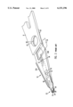
- FIG. 1 shows a fragmentary view of a prior art disk drive having an actuator arm assembly 2 and a stack of spaced apart disks 4 rotatable about a common spindle 5 as represented by the arrow 20.
- the actuator arm assembly 2 is also rotatable about an actuator arm axis 6.
- the arm assembly 2 includes a plurality of actuator arms 8A-8C which extend into the spaces between the disks 4A and 4B. Attached to each of the actuator arms 8A-8C is a magnetic head suspension assembly 10, which comprises a resilient load beam 12, a flexure 14 and a slider 16.
- Each load beam 12 is attached to one of the actuator arms 8A-8C via a base plate 25 having a boss 40 snugly inserted into the actuator hole 42 as shown in FIG. 1.
- FIG. 2 shows the magnetic head suspension assembly 10 in further detail.
- the load beam 12 is made of resilient material which is slightly bent toward the disk surface 18 (FIG. 1). Underneath the distal end of the load beam 12 is the flexure 14. An alignment hole 33 in the load beam 12 is provided for the alignment of the corresponding hole in the flexure 14, thereby orienting the flexure 14 in a proper location.
- the flexure 14 is fixedly attached onto the load beam 12 in the area surrounding the alignment hole 33 via welding.
- the flexure 14 has an integrally formed tongue portion 26. Fixedly attached to the tongue portion 26 is the slider 16. Stamped at the end of the load beam 12 is a dimple 28 which is urged against the tongue portion 26 of the flexure 14. The dimple 28 acts as the fulcrum for the resilient flexure 14 to provide gimbaling action. At the edge of the slider 16 is a magnetic head transducer 24. Electrical signals written in or read out of the transducer 24 are conducted by wires 30 disposed on the load beam 12 and guided by one of the load beam ribs 32A. As an alternative, a flex circuit 34 is used in lieu of the wires 30. Instead, electrical signals are sent or received through the traces 36 (shown partially as a representation in phantom) embedded on the flex substrate 38 of the flex circuit 34.
- the head gimbal assembly 22 is employed to accommodate the disk surface topology. Basically, the gimbal assembly 22 is designed to dynamically adjust the position of the slider 16 to conform to the irregular disk surface 18 while the disk is spinning. To meet this end, the flexure inside the gimbal assembly 22 must be sufficiently flexible and agile on one hand, yet stiff enough to resist physical deformation on the other hand.
- the magnetic suspension assembly 10 which includes the slider 16, the flexure 14,the load beam 12, the baseplate 25, and either the wires 30 or the flex circuit 34, needs to be tested prior to installation to a disk drive.
- testing of the magnetic head suspension assembly 10 involved inserting the entire assembly 10 into the arm of a spin station which performs the tests.
- the transducer 24 is the most delicately fabricated component. Often, the failure of the assembly 10 is the electrical malfunctioning of the transducer 24. Since the magnetic head suspension assembly 10 is permanently attached, the entire assembly 10 has to be rejected as a consequence.
- a slider is fabricated with a magnetic head transducer and then attached to an intermediate flexible circuit.
- the combination is thereafter inserted into a spin stand tester for the testing of various electrical parameters. If the attached combination fails the test, it is discarded. On the other hand, if the attached combination passes the test, it is mounted onto a load beam to form the magnetic head suspension assembly.
- the intermediate flexible circuit affixed with the slider is attached to a load beam having a flexure.
- the intermediate flexible circuit is attached to a load beam having no pre-disposed flexure, wherein the intermediate flexible circuit acts as the flexure in the final assembly.
- the magnetic heads which normally experience the highest failure rate, are isolated and rejected prior to final assembly, without affecting the associated components which are more expensive.
- FIG. 1, as described above, is a fragmentary view of a disk drive having a known magnetic head suspension assembly interacting with a plurality of disks;
- FIG. 2, as described above, is an enlarged perspective view of the known magnetic head suspension assembly attached to an actuator arm;
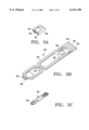
- FIG. 3A-3F are sequential views showing the steps of testing and fabricating the magnetic head suspension assembly in accordance with a first method of the invention
- FIG. 3G is an exploded view showing the relationship of the various components of the magnetic head suspension assembly fabricated in accordance with the method show in FIGS. 3A-3F;
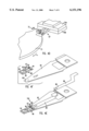
- FIG. 4A-4F are sequential views showing the steps of testing and fabricating the magnetic head suspension assembly in accordance with a second method of the invention.
- FIG. 4G is an exploded view showing the relationship of the various components of the magnetic head suspension assembly fabricated in accordance with the method shown in FIGS. 4A-4F;
- FIG. 4H is an enlarged view of the distal end of the flex circuit revealing the bonding tabs.
- FIGS. 3A-3F shows the method of manufacturing and testing a magnetic suspension assembly in accordance with the invention.
- the inventive process starts with providing a slider 50 having a magnetic head transducer 52 formed thereon.
- the magnetic head transducer 52 can be embedded within the slider 50.
- a relatively thick layer of alumina (Al 2 O 3 ) can be coated onto the trailing surface 54 of the slider 50.
- the magnetic head transducer 52 can be an inductive head, an anistropic magnetoresistive head (AMR), a giant magnetoresistive head (GMR), or a combination thereof as a merged head.
- AMR anistropic magnetoresistive head
- GMR giant magnetoresistive head
- a flexible interconnect flexible member 56 is provided as shown in FIG. 3B.
- the flexible member 56 is made of a flexible material such as polyimide.
- Formed on the flexible member 56 at the distal end 58 is an electrical footprint 60 for receiving the slider 50.
- Formed on the flexible member 56 at the proximal end 62 is a plurality of signal pads 64.
- the electrical footprint 60 and the signal pads 64 are electrically connected through electrical traces 66 formed on the sides of the flexible member 56.
- a tongue portion 59 for attaching the slider 50.
- the slider 50 is then mechanically attached to the tongue portion 59 of flexible member 56 as shown in FIG. 3C.
- the attachment can be achieved by different methods such as ultrasonic bonding, soldering, or adhesive bonding, for example.
- the slider 50 is attached to the flexible member 56 such that the slider bonding pads 55 correspondingly aligned with the footprint 60 on the flexible member 56.
- the bonding of the bonding pads 55 to the electrical footprint 60 can be accomplished through different methods such as ball bonding, tab bonding, stitch bonding or soldering.
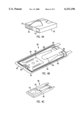
- FIG. 3D The slider 50 which is attached to the member 56, collectively called a combination 57, is inserted into the jaws 70A and 70B of a spin tester 72. Mechanical clamping and electrical connection (not shown) between the member 56 and the spin tester 72 are provided by the jaws 70A and 70B.
- a load mechanism 48 having a load tip 51 is then moved toward the combination 57.
- the load tip 51 is then slightly landed onto the slider 50 in the combination 57.
- the point of landing should be where the dimple 78 (see FIG. 3G) would eventually urge the slider 50 in the final assembly.
- the load mechanism 48 provides the simulated load force onto the slider 50 such that a predetermined flying height of the slider 50 above surface of the disk 73 (F The disk 73 of the spin tester 72 is then spun at an angular velocity T. At this juncture, various electrical tests are conducted.
- the flexible member 56 in this method by itself is relatively flexible and does not have a high degree of rigidity.
- the member 56 does not have adequate yaw stiffness by itself to withstand any high acceleration commonly encountered during track seeking in actual applications.
- the member 56 is stiff enough, and with the help of the load mechanism 48, to maintain the slider 50 at a predetermined flying height above the disk surface 73 to allow testing.
- the combination 57 fails the tests, the entire combination 57 is discarded. If the combination 57 passes the tests, the combination 57 is attached to a flexure 74, which is pre-welded onto the load beam 82, as shown in FIG. 3E. Specifically, the attachment is between the flexure tongue 76 and the flexible member tongue 59 (FIG. 3B). The attachment can be adhesive bonding or soldering, for instance. Mechanical attachment of the flexible member 56 to the flexure 74 at the proximal end 62 is optional.
- a flex circuit 86 is attached onto the load beam 82, as shown in FIG. 3F.
- the electrical pads 64 on the flexible member is soldered onto the corresponding pads (not shown) of the flex circuit 86.
- other attachment methods such as stitch bonding or tab bonding can also be employed.
- the flex circuit 86 can be securely attached to the proximal end portion 88 and the center portion 89 of the load beam 82.
- FIG. 3G shows an exploded view of the suspension assembly 84 illustrating the relative positions of the components in additional detail.
- FIGS. 4A-4F show a second method of testing and manufacturing of a magnetic suspension assembly in accordance with the invention.
- the magnetic head 52 can be embedded within the slider 50 and can be an inductive head, an anistropic magnetoresistive head (AMR), a giant magnetoresistive head (GMR), or a combination thereof as a merged head.
- a plurality of bonding pads 55 are deposited on the trailing surface 54 of the slider 50.
- a flexible interconnect flexible member 96 is then provided as shown in FIG. 4B.
- the flexible member 96 has a base substrate 93 made of flexible material.
- Exemplary material can be polyimide or stainless steel.
- the rigidity of the flexible member 96 in this method is higher than the corresponding rigidity of the flexible member 56 shown in the previous method. The reason is that the flexible member 96 used in this method also assumes the role as a flexure in the final assembly. That is, the flexible member 96 serves the dual function of acting as an interconnect member for testing and also as a flexure in the final assembly.
- the flexure member 96 has a pair of outriggers 95. Disposed between the outriggers 95 are a first tongue 98 and a second tongue 99. Formed on the flexible member 96 at the distal end 92 is an electrical footprint 60 for receiving the slider 50. Formed on the flexible member 96 at the proximal end 62 (FIG. 3E) is a plurality of signal pads 64. The slider footprint 60 and the signal pads 64 are electrically connected through electrical traces 66 formed on the sides of the flexible member 96. Electrical traces 66 and signal pads 60 and 64 are etched from a copper sheet that is attached to substrate 93 of the flexible member 56.
- the substrate 93 is made of conductive material such as steel, an insulating layer is sandwiched between the electrical traces, the signal pads 6slider 50 is then attached to the tongue 98 of the flexible member 96 as shown in FIG. 4C.
- the attachment can be achieved by different methods as described previously.
- the attachment of the slider 50 corresponds to and is in alignment with the footprint 60 of the flexible member 96. It should be noted that the slider 50 does not contact the outriggers 95 of the flexible member 96, thereby allowing the slider 50 to gimbal about the dimple 100 (FIG. 4G) during flight.
- the slider 50 with the magnetic head 52 in conjunction with the flexible member 96 is collectively called a combination 97.
- the combination 97 is first flipped over and inserted into the jaws 70A and 70B of a spin tester 72 as shown in FIG. 4D. Mechanical clamping and electrical connection (not shown) between the flexible member 96 and the spin tester 72 are provided by the jaws 70A and 70B.
- a load mechanism 48 having a load tip 51 is then moved toward the combination 57.
- the load tip 51 is then slightly landed onto the slider 50 in the combination 97.
- the point of landing should be where the dimple 100 (see FIG. 4G) would eventually urge the slider 50 in the final assembly.
- the load mechanism 48 provides the simulated load force onto the slider 50 such that a predetermined flying height of the slider 50 above the disk surface 73 can be maintained.
- the disk 73 of the spin tester 72 is then spun at an angular velocity. Electrical and connectivity tests are performed on the magnetic head 52 and electrical traces 66, respectively.
- the combination 97 fails the tests, the entire combination 97 is discarded. If the combination 97 passes the tests, in this method, the combination 97 is attached directly to a load beam 82.
- the flexible member 96 is made of polymeric material, attachment methods such as adhesive bonding or ultrasonic bonding can be used. If the flexible member 96 is made of metallic material, attachment methods such as adhesive bonding, soldering or welding can be employed.
- the areas of attachment are the second tongue 99 and the adjacent end 94 (FIG. 4E) of the flexible member 96, which areas are fixedly bonded onto the load beam 82. As mentioned before, in this method, the flexible member 96 also serves as a flexure in the final magnetic suspension assembly 104 (FIG. 4F).
- a flex circuit 86 is also attached to the load beam 82 as shown in FIG. 4F.
- the flex circuit 86 provides electrical connections to the flexible member 96.
- the flex circuit 86 can be securely attached to the proximal end 88 and the center portion 89 of the load beam 82.
- the electrical connection between the flex circuit 86 and the flexible member 96 can be by tab bonding of the flex circuit tabs 108 (FIG. 4H) to the signal pads 64 of the flexible member 96.
- Other bonding methods such as stitch bonding or reflow soldering can also be used.
- FIG. 4G shows an exploded view of the suspension assembly 104 illustrating the relative positions of the components in additional detail.
- the flexible interconnect members described in the specification are made of polyimide or stainless steel. Other materials can be used as substitutes.
Abstract
Description
Claims (3)
Priority Applications (2)
| Application Number | Priority Date | Filing Date | Title |
|---|---|---|---|
| US09/250,894 US6151196A (en) | 1999-02-16 | 1999-02-16 | Magnetic head suspension assembly including an intermediate flexible member that supports an air bearing slider with a magnetic transducer for testing |
| US09/612,883 US6708389B1 (en) | 1999-02-16 | 2000-07-10 | Method of forming a magnetic head suspension assembly |
Applications Claiming Priority (1)
| Application Number | Priority Date | Filing Date | Title |
|---|---|---|---|
| US09/250,894 US6151196A (en) | 1999-02-16 | 1999-02-16 | Magnetic head suspension assembly including an intermediate flexible member that supports an air bearing slider with a magnetic transducer for testing |
Related Child Applications (1)
| Application Number | Title | Priority Date | Filing Date |
|---|---|---|---|
| US09/612,883 Division US6708389B1 (en) | 1999-02-16 | 2000-07-10 | Method of forming a magnetic head suspension assembly |
Publications (1)
| Publication Number | Publication Date |
|---|---|
| US6151196A true US6151196A (en) | 2000-11-21 |
Family
ID=22949590
Family Applications (2)
| Application Number | Title | Priority Date | Filing Date |
|---|---|---|---|
| US09/250,894 Expired - Lifetime US6151196A (en) | 1999-02-16 | 1999-02-16 | Magnetic head suspension assembly including an intermediate flexible member that supports an air bearing slider with a magnetic transducer for testing |
| US09/612,883 Expired - Fee Related US6708389B1 (en) | 1999-02-16 | 2000-07-10 | Method of forming a magnetic head suspension assembly |
Family Applications After (1)
| Application Number | Title | Priority Date | Filing Date |
|---|---|---|---|
| US09/612,883 Expired - Fee Related US6708389B1 (en) | 1999-02-16 | 2000-07-10 | Method of forming a magnetic head suspension assembly |
Country Status (1)
| Country | Link |
|---|---|
| US (2) | US6151196A (en) |
Cited By (40)
| Publication number | Priority date | Publication date | Assignee | Title |
|---|---|---|---|---|
| US20010001588A1 (en) * | 1998-01-06 | 2001-05-24 | Robert T. J. Matz | Integrated lead head supension assembly having an etched laminated load beam and flexure with deposited conductors |
| WO2002017306A1 (en) * | 2000-08-23 | 2002-02-28 | Seagate Technology Llc | Method and apparatus using track scan data to qualify heads based on pes linearity |
| US6459260B1 (en) | 2001-06-12 | 2002-10-01 | Seagate Technology Llc | Head suspension assembly for testing a slider |
| WO2002100156A2 (en) * | 2001-06-12 | 2002-12-19 | Seagate Technology Llc | Head suspension assembly for a slider tester |
| US20030142445A1 (en) * | 2000-11-28 | 2003-07-31 | Peter Maimone | Method and apparatus for an active read/write head |
| US20060044695A1 (en) * | 2004-08-31 | 2006-03-02 | Hitachi Global Storage Technologies Netherlands B.V. | System and apparatus for continuous reference plane for wireless suspension and method of fabrication |
| US8929180B1 (en) | 2013-04-25 | 2015-01-06 | Western Digital Technologies, Inc. | Energy-assisted magnetic recording device having laser driving signal and magnetic write signal sharing same electrical conductor |
| US8934199B1 (en) | 2014-03-31 | 2015-01-13 | Western Digital Technologies, Inc. | Disk drive head suspension tail with bond pad edge alignment features |
| US8976491B1 (en) | 2013-05-09 | 2015-03-10 | Western Digital Technologies, Inc. | Disk drive head suspension distal non-op shock limiter with branched arms |
| US8988830B1 (en) | 2013-05-13 | 2015-03-24 | Western Digital (Fremont), Llc | Air bearing design to mitigate lube waterfall effect |
| US9042048B1 (en) | 2014-09-30 | 2015-05-26 | Western Digital (Fremont), Llc | Laser-ignited reactive HAMR bonding |
| US9064513B1 (en) | 2014-03-07 | 2015-06-23 | Western Digital Technologies, Inc. | Disk drive suspension assembly with flexure having dual conductive layers with staggered traces |
| US9070387B1 (en) | 2013-08-23 | 2015-06-30 | Western Digital Technologies, Inc. | Integrated heat-assisted magnetic recording head/laser assembly |
| US9093102B1 (en) | 2013-03-12 | 2015-07-28 | Western Digital Technologies, Inc. | Systems and methods for tuning seed layer hardness in components of magnetic recording systems |
| US9099145B1 (en) | 2013-12-24 | 2015-08-04 | Western Digital (Fremont), Llc | High contrast alignment marker |
| US9105282B1 (en) | 2013-05-20 | 2015-08-11 | Western Digital Technologies, Inc. | Head gimbal assembly carrier with adjustable protective bar |
| US9135935B1 (en) | 2013-10-11 | 2015-09-15 | Western Digital Technologies, Inc. | Customized head gimbal assembly bonding skew angle for adjusting two-dimensional magnetic recording reader alignment |
| US9165579B1 (en) | 2014-09-26 | 2015-10-20 | Western Digital (Fremont), Llc | Air bearing area configuration for reducing flying height hump across a stroke |
| US9171562B1 (en) | 2015-03-19 | 2015-10-27 | Western Digital (Fremont), Llc | Patterned metal layer to control solder connection between laser and submount in a magnetic head |
| US9183859B1 (en) | 2014-11-11 | 2015-11-10 | Western Digital (Fremont), Llc | HAMR writer pole length characterization |
| US9190090B1 (en) | 2014-12-24 | 2015-11-17 | Western Digital (Fremont), Llc | Multi step lube blocking air bearing area configuration |
| US9190089B1 (en) | 2014-12-24 | 2015-11-17 | Western Digital (Fremont), Llc | Air bearing area configuration for contaminating particle removal |
| US9202478B1 (en) | 2015-02-10 | 2015-12-01 | Western Digital (Fremont), Llc | Method and structure for soldering a laser submount to a mounting face of a slider |
| US9230580B1 (en) | 2010-06-30 | 2016-01-05 | Western Digital Technologies, Inc. | Suspension assembly having a microactuator grounded to a flexure |
| US9242340B1 (en) | 2013-03-12 | 2016-01-26 | Western Digital Technologies, Inc. | Method to stress relieve a magnetic recording head transducer utilizing ultrasonic cavitation |
| US9257138B1 (en) | 2014-10-28 | 2016-02-09 | Western Digital (Fremont), Llc | Slider assembly and method of manufacturing same |
| US9293157B1 (en) | 2012-06-28 | 2016-03-22 | Western Digital Technologies, Inc. | Automated active feedback slice and view milling of magnetic head cross-sections |
| US9315008B1 (en) | 2013-07-16 | 2016-04-19 | Western Digital Technologies, Inc. | Method and apparatus for aligning an illumination unit to a slider for a magnetic recording device |
| US9343084B2 (en) | 2012-03-14 | 2016-05-17 | Western Digital Technologies, Inc. | Systems and methods for correcting slider parallelism error using compensation lapping |
| US9361916B1 (en) | 2014-03-13 | 2016-06-07 | Western Digital (Fremont) | Electrical lapping guide for dimensional control of back side of heat assisted magnetic recording device |
| US9368139B1 (en) | 2015-03-20 | 2016-06-14 | Western Digital (Fremont), Llc | Slider back side etching to increase shear strength between suspension and slider |
| US9372078B1 (en) | 2014-06-20 | 2016-06-21 | Western Digital (Fremont), Llc | Detecting thickness variation and quantitative depth utilizing scanning electron microscopy with a surface profiler |
| US9387568B1 (en) | 2013-02-27 | 2016-07-12 | Western Digital Technologies, Inc. | Systems and methods for correcting fabrication error in magnetic recording heads using magnetic write width measurements |
| US9431044B1 (en) | 2014-05-07 | 2016-08-30 | Western Digital (Fremont), Llc | Slider having shock and particle resistance |
| US9431037B2 (en) | 2013-03-12 | 2016-08-30 | Western Digitatl (Fremont), LLC | Systems and methods for monitoring the power of a light source utilized in energy-assisted magnetic recording |
| US9659587B1 (en) | 2015-11-06 | 2017-05-23 | Western Digital (Fremont), Llc | Magnetic head having a reader overcoat with DLC and a recessed writer overcoat without DLC |
| US9659589B2 (en) | 2015-09-29 | 2017-05-23 | Western Digital (Fremont), Llc | Free-standing reflector usable in heat assisted magnetic recording technology |
| US9685187B1 (en) | 2014-09-26 | 2017-06-20 | Western Digital (Fremont), Llc | Bonding tool and method for high accuracy chip-to-chip bonding |
| US9805748B1 (en) | 2014-06-24 | 2017-10-31 | Western Digital (Fremont), Llc | System and method for providing a protective layer having a graded intermediate layer |
| US9870788B2 (en) | 2014-01-08 | 2018-01-16 | Western Digital (Fremont), Llc | Method of adjusting tilt using magnetic erase width feedback |
Families Citing this family (12)
| Publication number | Priority date | Publication date | Assignee | Title |
|---|---|---|---|---|
| US8929033B2 (en) * | 2005-05-02 | 2015-01-06 | HGST Netherlands B.V. | Flexure for implementation on a suspension in a hard disk drive for resisting windage effects |
| US7701675B2 (en) * | 2005-12-16 | 2010-04-20 | Sae Magnetics (H.K.) Ltd. | Micro-actuator mounting structure capable of maintaining a substantially constant gap between a top support of a micro-actuator and a suspension during use |
| US8098460B1 (en) | 2009-06-30 | 2012-01-17 | Western Digital Technologies, Inc. | Dual-state clamping mechanism |
| US8094414B1 (en) | 2009-07-09 | 2012-01-10 | Western Digital Technologies, Inc. | Head gimbal assembly mounting mechanism |
| US9633680B2 (en) | 2010-10-29 | 2017-04-25 | Western Digital Technologies, Inc. | Head suspension having a flexure tail with a covered conductive layer and structural layer bond pads |
| US9165580B2 (en) | 2013-12-10 | 2015-10-20 | Western Digital Technologies, Inc. | Disk drive head suspension tail with stiffened edge alignment features |
| US8467153B1 (en) | 2010-10-29 | 2013-06-18 | Western Digital Technologies, Inc. | Disk drive head gimbal assembly having a flexure tail with folded bond pads |
| US9324344B1 (en) | 2013-12-10 | 2016-04-26 | Western Digital Technologies, Inc. | Disk drive head suspension tail with ground pad outside of bonding region |
| US8339747B1 (en) | 2011-03-11 | 2012-12-25 | Western Digital Technologies, Inc. | Removable actuator assemblies for testing head gimbal assemblies of a storage device |
| US8705209B2 (en) | 2011-10-14 | 2014-04-22 | Western Digital Technologies, Inc. | Suspension clamp for clamping a disk drive suspension to an actuator arm |
| US8760812B1 (en) | 2011-12-20 | 2014-06-24 | Western Digital Technologies, Inc. | Disk drive head gimbal assembly having a jumper in a flexible printed circuit overlap region |
| US9330695B1 (en) | 2013-12-10 | 2016-05-03 | Western Digital Technologies, Inc. | Disk drive head suspension tail with a noble metal layer disposed on a plurality of structural backing islands |
Citations (4)
| Publication number | Priority date | Publication date | Assignee | Title |
|---|---|---|---|---|
| US5924187A (en) * | 1998-01-06 | 1999-07-20 | Hutchinson Technology Incorporated | Integrated lead head suspension assembly having an etched laminated load beam and flexure with deposited conductors |
| US5933293A (en) * | 1997-06-25 | 1999-08-03 | Hutchinson Technology, Inc. | Head suspension load beam having a low profile integrated flexure |
| US6046887A (en) * | 1997-07-11 | 2000-04-04 | Nhk Spring Co., Ltd. | Suspension for disc drive |
| US6057986A (en) * | 1997-07-23 | 2000-05-02 | Suncall Corporation | Support mechanism for magnetic head sliders and method for producing the same |
Family Cites Families (5)
| Publication number | Priority date | Publication date | Assignee | Title |
|---|---|---|---|---|
| US5404636A (en) * | 1993-11-12 | 1995-04-11 | Conner Peripherals, Inc. | Method of assembling a disk drive actuator |
| US5589771A (en) * | 1994-10-24 | 1996-12-31 | Swan Instruments, Inc. | Magnetic media head dynamic testing apparatus and method which operate by deforming a localized portion of magnetic media toward the head element |
| US5574234A (en) * | 1995-05-01 | 1996-11-12 | K. R. Precision Co., Ltd. | Floating-ball device for precise axial alignment between opposing structures |
| US5758406A (en) * | 1997-02-07 | 1998-06-02 | Read-Rite Corporation | Method for assembling and electrical testing of a magnetic head |
| JPH11195214A (en) * | 1997-12-26 | 1999-07-21 | Tdk Corp | Manufacture of magnetic head device |
-
1999
- 1999-02-16 US US09/250,894 patent/US6151196A/en not_active Expired - Lifetime
-
2000
- 2000-07-10 US US09/612,883 patent/US6708389B1/en not_active Expired - Fee Related
Patent Citations (4)
| Publication number | Priority date | Publication date | Assignee | Title |
|---|---|---|---|---|
| US5933293A (en) * | 1997-06-25 | 1999-08-03 | Hutchinson Technology, Inc. | Head suspension load beam having a low profile integrated flexure |
| US6046887A (en) * | 1997-07-11 | 2000-04-04 | Nhk Spring Co., Ltd. | Suspension for disc drive |
| US6057986A (en) * | 1997-07-23 | 2000-05-02 | Suncall Corporation | Support mechanism for magnetic head sliders and method for producing the same |
| US5924187A (en) * | 1998-01-06 | 1999-07-20 | Hutchinson Technology Incorporated | Integrated lead head suspension assembly having an etched laminated load beam and flexure with deposited conductors |
Cited By (49)
| Publication number | Priority date | Publication date | Assignee | Title |
|---|---|---|---|---|
| US20010001588A1 (en) * | 1998-01-06 | 2001-05-24 | Robert T. J. Matz | Integrated lead head supension assembly having an etched laminated load beam and flexure with deposited conductors |
| US6700747B2 (en) * | 1998-01-06 | 2004-03-02 | Hutchinson Technology Incorporated | Integrated lead head suspension assembly having an etched laminated load beam and flexure with deposited conductors |
| US6608477B2 (en) | 2000-08-23 | 2003-08-19 | Seagate Technology Llc | Apparatus and method for altering track scan data based on head width relative to data track width and determining the position error signal from the altered track scan data to qualify the head in a data storage device |
| WO2002017306A1 (en) * | 2000-08-23 | 2002-02-28 | Seagate Technology Llc | Method and apparatus using track scan data to qualify heads based on pes linearity |
| GB2381940B (en) * | 2000-08-23 | 2004-06-23 | Seagate Technology Llc | Method and apparatus using track scan data to qualify heads based on PES linearity |
| GB2381940A (en) * | 2000-08-23 | 2003-05-14 | Seagate Technology Llc | Method and apparatus using track scan data to qualify heads based on pes linearity |
| US20030142445A1 (en) * | 2000-11-28 | 2003-07-31 | Peter Maimone | Method and apparatus for an active read/write head |
| US7095594B2 (en) * | 2000-11-28 | 2006-08-22 | Texas Instruments Incorporated | Active read/write head circuit with interface circuit |
| WO2002100156A3 (en) * | 2001-06-12 | 2003-03-20 | Seagate Technology Llc | Head suspension assembly for a slider tester |
| WO2002100156A2 (en) * | 2001-06-12 | 2002-12-19 | Seagate Technology Llc | Head suspension assembly for a slider tester |
| CN100342428C (en) * | 2001-06-12 | 2007-10-10 | 希捷科技有限公司 | Head suspension assembly for slider tester |
| US6459260B1 (en) | 2001-06-12 | 2002-10-01 | Seagate Technology Llc | Head suspension assembly for testing a slider |
| US20060044695A1 (en) * | 2004-08-31 | 2006-03-02 | Hitachi Global Storage Technologies Netherlands B.V. | System and apparatus for continuous reference plane for wireless suspension and method of fabrication |
| US7349184B2 (en) * | 2004-08-31 | 2008-03-25 | Hitachi Global Storage Technologies | System and apparatus for continuous reference plane for wireless suspension |
| US9230580B1 (en) | 2010-06-30 | 2016-01-05 | Western Digital Technologies, Inc. | Suspension assembly having a microactuator grounded to a flexure |
| US9343084B2 (en) | 2012-03-14 | 2016-05-17 | Western Digital Technologies, Inc. | Systems and methods for correcting slider parallelism error using compensation lapping |
| US9293157B1 (en) | 2012-06-28 | 2016-03-22 | Western Digital Technologies, Inc. | Automated active feedback slice and view milling of magnetic head cross-sections |
| US9387568B1 (en) | 2013-02-27 | 2016-07-12 | Western Digital Technologies, Inc. | Systems and methods for correcting fabrication error in magnetic recording heads using magnetic write width measurements |
| US9242340B1 (en) | 2013-03-12 | 2016-01-26 | Western Digital Technologies, Inc. | Method to stress relieve a magnetic recording head transducer utilizing ultrasonic cavitation |
| US9093102B1 (en) | 2013-03-12 | 2015-07-28 | Western Digital Technologies, Inc. | Systems and methods for tuning seed layer hardness in components of magnetic recording systems |
| US9449631B2 (en) | 2013-03-12 | 2016-09-20 | Western Digital Technologies, Inc. | Slider for magnetic recording system |
| US9431037B2 (en) | 2013-03-12 | 2016-08-30 | Western Digitatl (Fremont), LLC | Systems and methods for monitoring the power of a light source utilized in energy-assisted magnetic recording |
| US8929180B1 (en) | 2013-04-25 | 2015-01-06 | Western Digital Technologies, Inc. | Energy-assisted magnetic recording device having laser driving signal and magnetic write signal sharing same electrical conductor |
| US8976491B1 (en) | 2013-05-09 | 2015-03-10 | Western Digital Technologies, Inc. | Disk drive head suspension distal non-op shock limiter with branched arms |
| US8988830B1 (en) | 2013-05-13 | 2015-03-24 | Western Digital (Fremont), Llc | Air bearing design to mitigate lube waterfall effect |
| US9105282B1 (en) | 2013-05-20 | 2015-08-11 | Western Digital Technologies, Inc. | Head gimbal assembly carrier with adjustable protective bar |
| US9315008B1 (en) | 2013-07-16 | 2016-04-19 | Western Digital Technologies, Inc. | Method and apparatus for aligning an illumination unit to a slider for a magnetic recording device |
| US9070387B1 (en) | 2013-08-23 | 2015-06-30 | Western Digital Technologies, Inc. | Integrated heat-assisted magnetic recording head/laser assembly |
| US9135935B1 (en) | 2013-10-11 | 2015-09-15 | Western Digital Technologies, Inc. | Customized head gimbal assembly bonding skew angle for adjusting two-dimensional magnetic recording reader alignment |
| US9099145B1 (en) | 2013-12-24 | 2015-08-04 | Western Digital (Fremont), Llc | High contrast alignment marker |
| US9870788B2 (en) | 2014-01-08 | 2018-01-16 | Western Digital (Fremont), Llc | Method of adjusting tilt using magnetic erase width feedback |
| US9064513B1 (en) | 2014-03-07 | 2015-06-23 | Western Digital Technologies, Inc. | Disk drive suspension assembly with flexure having dual conductive layers with staggered traces |
| US9361916B1 (en) | 2014-03-13 | 2016-06-07 | Western Digital (Fremont) | Electrical lapping guide for dimensional control of back side of heat assisted magnetic recording device |
| US8934199B1 (en) | 2014-03-31 | 2015-01-13 | Western Digital Technologies, Inc. | Disk drive head suspension tail with bond pad edge alignment features |
| US9431044B1 (en) | 2014-05-07 | 2016-08-30 | Western Digital (Fremont), Llc | Slider having shock and particle resistance |
| US9372078B1 (en) | 2014-06-20 | 2016-06-21 | Western Digital (Fremont), Llc | Detecting thickness variation and quantitative depth utilizing scanning electron microscopy with a surface profiler |
| US9805748B1 (en) | 2014-06-24 | 2017-10-31 | Western Digital (Fremont), Llc | System and method for providing a protective layer having a graded intermediate layer |
| US9165579B1 (en) | 2014-09-26 | 2015-10-20 | Western Digital (Fremont), Llc | Air bearing area configuration for reducing flying height hump across a stroke |
| US9685187B1 (en) | 2014-09-26 | 2017-06-20 | Western Digital (Fremont), Llc | Bonding tool and method for high accuracy chip-to-chip bonding |
| US9042048B1 (en) | 2014-09-30 | 2015-05-26 | Western Digital (Fremont), Llc | Laser-ignited reactive HAMR bonding |
| US9257138B1 (en) | 2014-10-28 | 2016-02-09 | Western Digital (Fremont), Llc | Slider assembly and method of manufacturing same |
| US9183859B1 (en) | 2014-11-11 | 2015-11-10 | Western Digital (Fremont), Llc | HAMR writer pole length characterization |
| US9190090B1 (en) | 2014-12-24 | 2015-11-17 | Western Digital (Fremont), Llc | Multi step lube blocking air bearing area configuration |
| US9190089B1 (en) | 2014-12-24 | 2015-11-17 | Western Digital (Fremont), Llc | Air bearing area configuration for contaminating particle removal |
| US9202478B1 (en) | 2015-02-10 | 2015-12-01 | Western Digital (Fremont), Llc | Method and structure for soldering a laser submount to a mounting face of a slider |
| US9171562B1 (en) | 2015-03-19 | 2015-10-27 | Western Digital (Fremont), Llc | Patterned metal layer to control solder connection between laser and submount in a magnetic head |
| US9368139B1 (en) | 2015-03-20 | 2016-06-14 | Western Digital (Fremont), Llc | Slider back side etching to increase shear strength between suspension and slider |
| US9659589B2 (en) | 2015-09-29 | 2017-05-23 | Western Digital (Fremont), Llc | Free-standing reflector usable in heat assisted magnetic recording technology |
| US9659587B1 (en) | 2015-11-06 | 2017-05-23 | Western Digital (Fremont), Llc | Magnetic head having a reader overcoat with DLC and a recessed writer overcoat without DLC |
Also Published As
| Publication number | Publication date |
|---|---|
| US6708389B1 (en) | 2004-03-23 |
Similar Documents
| Publication | Publication Date | Title |
|---|---|---|
| US6151196A (en) | Magnetic head suspension assembly including an intermediate flexible member that supports an air bearing slider with a magnetic transducer for testing | |
| US7777991B2 (en) | Head gimbal assembly with improved interconnection between head slider and suspension, fabricating method thereof, and magnetic disk drive with the same | |
| US8045295B2 (en) | Method and apparatus for providing an additional ground pad and electrical connection for grounding a magnetic recording head | |
| US7059868B1 (en) | Connection of trace circuitry in a computer disk drive system | |
| EP0888610B1 (en) | Adjustable solder bump spacer for slider-suspension attachment | |
| US6459260B1 (en) | Head suspension assembly for testing a slider | |
| US7688552B2 (en) | Head gimbal assembly having dimple-shaft limiter and manufacturing method thereof and disk drive unit with the same | |
| US5896247A (en) | Disk file suspension formed flexure | |
| US6144531A (en) | Magnetic head assembly having a suspension with a loading projection and manufacturing method thereof | |
| US7593191B2 (en) | HGA having separate dimple element, disk drive unit with the same, and manufacturing method thereof | |
| JP2006004599A (en) | Method for providing electrical crossover in laminated structure | |
| US9972347B1 (en) | Method for head stack assembly rework | |
| JP2001501762A (en) | Flex circuit flexure with integrated high compliance gimbal | |
| US8446696B2 (en) | Suspension having a short flexure tail, head gimbal assembly and disk drive unit with the same | |
| US6400529B1 (en) | Integrated circuit chip supporting and electrically connecting a head slider | |
| US8320081B2 (en) | Magnetic recording head, head gimbal assembly, and disk drive unit with the same | |
| US20030128474A1 (en) | Low electrical impedance slider grounding | |
| US7116523B2 (en) | Interconnect module for use in a suspension assembly | |
| US6687090B2 (en) | Head suspension assembly with head amplifier IC | |
| US7924531B2 (en) | Suspension and fabricating method thereof, head gimbal assembly and disk drive device | |
| US20020057531A1 (en) | HGA ballbond assembly with wafer process assembly features | |
| US20020131210A1 (en) | Method of manufacturing head suspension assembly and head suspension assembly | |
| US20040240115A1 (en) | One-piece suspension assembly including interconnect | |
| JP2004164813A (en) | Low impedance electrical grounding for slider | |
| JP3662562B2 (en) | Magnetic head support mechanism, magnetic head support device, and magnetic disk device |
Legal Events
| Date | Code | Title | Description |
|---|---|---|---|
| AS | Assignment |
Owner name: READ-RITE CORPORATION, CALIFORNIA Free format text: ASSIGNMENT OF ASSIGNORS INTEREST;ASSIGNORS:CARLSON, CARL J.;SCHOTT, DANIEL P.;REEL/FRAME:009794/0812 Effective date: 19990202 |
|
| STCF | Information on status: patent grant |
Free format text: PATENTED CASE |
|
| AS | Assignment |
Owner name: TENNENBAUM CAPITAL PARTNERS, LLC, CALIFORNIA Free format text: SECURITY INTEREST;ASSIGNOR:READ-RITE CORPORATION;REEL/FRAME:013616/0399 Effective date: 20021224 |
|
| AS | Assignment |
Owner name: WESTERN DIGITAL (FREMONT), INC., CALIFORNIA Free format text: ASSIGNMENT OF ASSIGNORS INTEREST;ASSIGNOR:READ-RITE CORPORATION;REEL/FRAME:014506/0765 Effective date: 20030731 |
|
| AS | Assignment |
Owner name: READ-RITE CORPORATION, CALIFORNIA Free format text: RELEASE OF SECURITY INTEREST;ASSIGNOR:TENNENBAUM CAPITAL PARTNERS, LLC;REEL/FRAME:014499/0476 Effective date: 20030731 |
|
| FPAY | Fee payment |
Year of fee payment: 4 |
|
| AS | Assignment |
Owner name: GENERAL ELECTRIC CAPITAL CORPORATION, AS AGENT, CA Free format text: SECURITY INTEREST;ASSIGNORS:WESTERN DIGITAL TECHNOLOGIES, INC.;WESTERN DIGITAL (FREMONT), INC.;REEL/FRAME:014830/0957 Effective date: 20030919 |
|
| AS | Assignment |
Owner name: WESTERN DIGITAL (FREMONT), INC., CALIFORNIA Free format text: RELEASE BY SECURED PARTY;ASSIGNOR:GENERAL ELECTRIC CAPITAL CORPORATION, AS AGENT;REEL/FRAME:020599/0489 Effective date: 20070809 Owner name: WESTERN DIGITAL TECHNOLOGIES, INC., CALIFORNIA Free format text: RELEASE BY SECURED PARTY;ASSIGNOR:GENERAL ELECTRIC CAPITAL CORPORATION, AS AGENT;REEL/FRAME:020599/0489 Effective date: 20070809 |
|
| FPAY | Fee payment |
Year of fee payment: 8 |
|
| FPAY | Fee payment |
Year of fee payment: 12 |
|
| AS | Assignment |
Owner name: JPMORGAN CHASE BANK, N.A., AS COLLATERAL AGENT, IL Free format text: SECURITY AGREEMENT;ASSIGNOR:WESTERN DIGITAL (FREMONT), LLC;REEL/FRAME:038710/0845 Effective date: 20160512 Owner name: JPMORGAN CHASE BANK, N.A., AS COLLATERAL AGENT, IL Free format text: SECURITY AGREEMENT;ASSIGNOR:WESTERN DIGITAL (FREMONT), LLC;REEL/FRAME:038744/0755 Effective date: 20160512 Owner name: U.S. BANK NATIONAL ASSOCIATION, AS COLLATERAL AGEN Free format text: SECURITY AGREEMENT;ASSIGNOR:WESTERN DIGITAL (FREMONT), LLC;REEL/FRAME:038744/0675 Effective date: 20160512 |
|
| AS | Assignment |
Owner name: WESTERN DIGITAL (FREMONT), LLC, CALIFORNIA Free format text: RELEASE BY SECURED PARTY;ASSIGNOR:U.S. BANK NATIONAL ASSOCIATION, AS COLLATERAL AGENT;REEL/FRAME:045501/0158 Effective date: 20180227 |
|
| AS | Assignment |
Owner name: WESTERN DIGITAL (FREMONT), LLC, CALIFORNIA Free format text: ENTITY CONVERSION FROM INC TO LLC;ASSIGNOR:WESTERN DIGITAL (FREMONT), INC;REEL/FRAME:048501/0925 Effective date: 20070629 |
|
| AS | Assignment |
Owner name: WESTERN DIGITAL TECHNOLOGIES, INC., CALIFORNIA Free format text: ASSIGNMENT OF ASSIGNORS INTEREST;ASSIGNOR:WESTERN DIGITAL (FREMONT), LLC;REEL/FRAME:050450/0582 Effective date: 20190508 |
|
| AS | Assignment |
Owner name: WESTERN DIGITAL TECHNOLOGIES, INC., CALIFORNIA Free format text: RELEASE OF SECURITY INTEREST AT REEL 038710 FRAME 0845;ASSIGNOR:JPMORGAN CHASE BANK, N.A.;REEL/FRAME:058965/0445 Effective date: 20220203 Owner name: WESTERN DIGITAL (FREMONT), LLC, CALIFORNIA Free format text: RELEASE OF SECURITY INTEREST AT REEL 038710 FRAME 0845;ASSIGNOR:JPMORGAN CHASE BANK, N.A.;REEL/FRAME:058965/0445 Effective date: 20220203 |