US6151183A - Disk drive device and method for controlling the same - Google Patents
Disk drive device and method for controlling the same Download PDFInfo
- Publication number
- US6151183A US6151183A US09/079,876 US7987698A US6151183A US 6151183 A US6151183 A US 6151183A US 7987698 A US7987698 A US 7987698A US 6151183 A US6151183 A US 6151183A
- Authority
- US
- United States
- Prior art keywords
- read
- write
- value
- head
- atmospheric pressure
- Prior art date
- Legal status (The legal status is an assumption and is not a legal conclusion. Google has not performed a legal analysis and makes no representation as to the accuracy of the status listed.)
- Expired - Lifetime
Links
Images
Classifications
-
- G—PHYSICS
- G11—INFORMATION STORAGE
- G11B—INFORMATION STORAGE BASED ON RELATIVE MOVEMENT BETWEEN RECORD CARRIER AND TRANSDUCER
- G11B21/00—Head arrangements not specific to the method of recording or reproducing
- G11B21/16—Supporting the heads; Supporting the sockets for plug-in heads
- G11B21/20—Supporting the heads; Supporting the sockets for plug-in heads while the head is in operative position but stationary or permitting minor movements to follow irregularities in surface of record carrier
- G11B21/21—Supporting the heads; Supporting the sockets for plug-in heads while the head is in operative position but stationary or permitting minor movements to follow irregularities in surface of record carrier with provision for maintaining desired spacing of head from record carrier, e.g. fluid-dynamic spacing, slider
-
- G—PHYSICS
- G11—INFORMATION STORAGE
- G11B—INFORMATION STORAGE BASED ON RELATIVE MOVEMENT BETWEEN RECORD CARRIER AND TRANSDUCER
- G11B21/00—Head arrangements not specific to the method of recording or reproducing
- G11B21/02—Driving or moving of heads
- G11B21/08—Track changing or selecting during transducing operation
- G11B21/081—Access to indexed tracks or parts of continuous track
- G11B21/083—Access to indexed tracks or parts of continuous track on discs
-
- G—PHYSICS
- G11—INFORMATION STORAGE
- G11B—INFORMATION STORAGE BASED ON RELATIVE MOVEMENT BETWEEN RECORD CARRIER AND TRANSDUCER
- G11B5/00—Recording by magnetisation or demagnetisation of a record carrier; Reproducing by magnetic means; Record carriers therefor
- G11B5/48—Disposition or mounting of heads or head supports relative to record carriers ; arrangements of heads, e.g. for scanning the record carrier to increase the relative speed
- G11B5/58—Disposition or mounting of heads or head supports relative to record carriers ; arrangements of heads, e.g. for scanning the record carrier to increase the relative speed with provision for moving the head for the purpose of maintaining alignment of the head relative to the record carrier during transducing operation, e.g. to compensate for surface irregularities of the latter or for track following
- G11B5/60—Fluid-dynamic spacing of heads from record-carriers
- G11B5/6005—Specially adapted for spacing from a rotating disc using a fluid cushion
- G11B5/6011—Control of flying height
Definitions
- the present invention relates to a method for controlling the operation of a hard disk drive device based upon a detected value of surrounding atmospheric pressure and a hard disk drive device capable of controlling its operation based upon the detected value of the atmospheric pressure.
- At least one magnetic recording disk is contained in a hard disk drive device, and the data is stored on both surfaces of the magnetic recording disk.
- One read/write head is provided on each recording surface.
- four read/write heads are used with two recording disks; each read/write head is mounted on a front end of a head support arm, and rear ends of four head support arms are so connected to each other that all the read/write heads address the same radial cylinder positions on each of the four recording surfaces of the two recording disks. In this manner, all the read/write heads address the same radial positions of the four recording surfaces which define a cylinder, and as such the radial cylinder positions are called cylinder position.
- a prior hard disk drive device used a contact start/stop scheme in which a head/slider assembly is landed on a rest region or a non-recording region located inside the inner most recording cylinder of a magnetic recording disk during a power off period, and takes off from the surface of the rest region when the magnetic recording disk is rotated.
- the surface of the disk must be roughened. The reasons for forming the roughness on the recording surface is that if the surface is made smooth, the head/slider assembly sticks to the recording surface due to interatomic forces, thereby preventing take off.
- a flying height of the head/slider assembly i.e., a space between the head/slider assembly and the recording surface of the disk has been decreased.
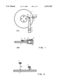
- a hard disk drive device which uses a load/unload scheme in which a ramp element 2 is mounted at the peripheral of the magnetic recording disk 1, as shown in the FIGS. 1(A) and 1(B).
- the surface of the ramp element 2 is ramped, and a front end 3 of a head support arm 4 rides on the ramped surface of the part 2, and moves in the direction of an arrow 6 to the rest position of the ramp element 2, as shown in FIG. 1(B), when the head support arm 4 is rotated around a pivot point 5 in the clockwise direction in FIG. 1(A).
- the magnetic recording disk 1 is rotated by a motor, not shown, and the head support arm 4 is moved from the rest position in a direction of an arrow 8, and is moved to a flying position above the desired cylinder of the magnetic recording disk 1 to read the data from the cylinder or write the data into the cylinder.
- the rotational speed, i.e., the revolution per minute (RPM), of the magnetic recording disk 1 is so designed to generate an air bearing with an appropriate pressure which causes the head/slider assembly 7 of the head support arm 4 to fly above the surface of the magnetic recording disk 1.
- RPM revolution per minute
- the head/slider assembly 7 does not land on the surface of the disk 1, so that the surface of the disk 1 can be polished to remove the roughness of the surface of the disk used in the contact start/stop scheme, and the flying height of the head/slider arm 4 in the read/write mode and an error recovery mode can be reduced in comparison with the flying height of the contact start/stop scheme.
- the flying height of the head/slider assembly 7 is maintained at the height H1 by maintaining the first rotation speed. If the hard disk drive device senses a read error or a write error, the hard disk drive device enters the error recovery mode by reducing the rotational speed of the disk 1 to a second rotational speed which is lower than the first rotational speed to maintain the height H2. This height H2 is so selected to bring the lower surface of the head/slider assembly 7 close to the surface of the disk 1 to wipe off any dusts or residual material on the surface of the magnetic recording disk 1.
- the problem found by the inventors of the present invention is that the head/slider assembly 7 tends to stick to the surface of the magnetic recording disk 1 when the hard disk drive device enters the error recovery mode while the hard disk drive device is used in an airplane flying at a high altitude.
- a method for controlling a hard disk drive device operated in an unknown atmospheric pressure.
- a read/write head mounted on a head support arm flies above a surface of a rotating recording disk, and the head support arm is moved by a head moving means along a radial direction to position the read/write head over one of the cylinder positions of the recording disk.
- a value of the unknown atmospheric pressure is detected during a power on reset period before a read/write period.
- the information indicating whether the detected value of the unknown atmospheric pressure is lower than a threshold value is stored in a memory.
- the stored information is used during the read/write period to determine whether an operation for lowering a flying height of the read/write head to a height which is lower than a height for the read/write operation should be inhibited.
- the value of the unknown atmospheric pressure is detected by the steps of (i) detecting a current value applied to the head moving means to keep the read/write head at a selected cylinder position, (ii) comparing the detected current value with a reference current value which represents a current value applied to the head moving means to keep the read/write head at the selected cylinder position at a reference atmospheric pressure, (iii) generating a difference value between the detected current value and the reference current value, and (iv) comparing the difference value with a threshold value to generate the information.
- the operation for lowering the flying height of the read/write head is inhibited.
- the selected cylinder position is at least one cylinder position of the outer most cylinder position and the inner most cylinder position.
- FIGS. 1(A) and 1(B) show the load/unload operation of the hard disk drive device.
- FIG. 2 shows the flying height of the head in the read/write operation.
- FIG. 3 shows the various force generated on the head support arm.
- FIG. 4 shows the block diagram of the circuit of the hard disk drive device.
- FIG. 5 shows the current applied to the VCM.
- FIG. 6 shows the drag force F DRAG .
- FIG. 7 shows the difference value ⁇ I VCM and the atmospheric pressure.
- FIG. 8 shows the flow chart of the operation performed during the POR period in accordance with the present invention.
- FIG. 9 shows the flow chart of the operation performed during the read/write period in accordance with the present invention.
- the flying heights H1 and H2 in the read/write mode and the error recovery mode are determined at atmospheric pressure
- the pressure of the air bearing between the head/slider assembly 7 and the surface of the magnetic recording disk 1 is mainly determined by (a) the rotational speed of the disk 1 and (b) the value of the surrounding atmospheric pressure.
- the inventors of the present invention have performed an analysis of the effects of the atmospheric pressure on the air bearing.
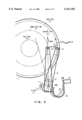
- FIG. 3 shows the magnetic recording disk 1 and the head support arm 4 pivoted at the pivot point 5. Only a read/write head 9 is shown in FIG. 3 for simplifying the drawing.
- One end 10A of a flexible cable 10 having a plurality of electrically conductive wires is connected to the rear end of the head support arm 4. These wires are used to apply data signals to the head 9 and receive from the read/write head 9 the data signals and the position signals read from each of the radial positions, i.e., the cylinders, of the magnetic recording disk 1.
- the other end 10B of the flexible cable 10 is connected to a read/write circuit 12.
- the movement of the head support arm 4 and the read/write head 9 in the radial direction of the recording disk 1 is controlled by a voice coil motor (VCM) 11.
- VCM voice coil motor
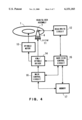
- FIG. 4 shows a block diagram of the circuits included in the hard disk drive device.
- a spindle motor 13 for rotating the magnetic recording disk 1 and the VCM 11 are controlled by a VCM/spindle driver 14.
- the read/write circuit 12 is connected to a hard disk control circuit 15, which in turn is also connected to the VCM/spindle driver 14.
- a memory 17 is connected to the circuit 15 and a main control circuit 16, which controls the VCM/spindle driver 14, the hard disk control circuit 15 and the memory 17.
- end 10A applies a force to the rear end of the head support arm 4.
- This force of the flexible cable 10 applied to the rear end of the head support arm 4 is adjusted to keep the read/write head 9 of the head support arm 4 at the home cylinder position "6" (i.e., the center line 13 of the magnetic recording head) when the VCM 11 is not activated.
- the flexible cable 10 applies a bias force to the head support arm 4 to position the head 9 at the home cylinder position "6", when the VCM 11 is not activated.
- the read/write head 9 is held at the home cylinder position "6" by the force applied by the flexible cable 10 when the VCM 11 is not activated.
- the VCM 11 is then activated to move the head 9 from the home cylinder position "6" to any cylinder position, such as the outer most cylinder position "12" or the inner most cylinder position "0".
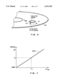
- the values of current applied to the VCM 11 by the VCM/spindle driver 14 are shown in FIG. 5 as Curve 1 and Curve 2.
- a vertical axis indicates the values of the current I VCM applied to the VCM 11, and a horizontal axis indicates the radial cylinder positions along the radial of the magnetic recording disk 1. For simplifying the description, only thirteen cylinder positions "0" through “12" are shown in FIG. 5.
- the head 9 is positioned at the home cylinder position "6" by the bias force of the flexible cable 10.
- the Curve 1 indicates the current required to move the head support arm 4 under the reference atmospheric pressure on the ground.
- the values of the Curve 1 is stored in the memory 17 at the shipment of the hard disk drive device.
- the Curve 2 indicates one example of the values detected by the main control circuit 16. It is assumed that the values of the Curve 2 are detected in the air plane flying at the high altitude, i.e., in a reduced atmospheric pressure which is lower than the reference atmospheric pressure.
- the main control circuit 16 shown in FIG. 4 detects the values of the Curve 2 during the Power On Reset (POR) in accordance with the present invention.
- the POR means a period from the time of the power on by the operator to the time of the start of the read/write operation. During the POR, the operation in accordance with the present invention and other diagnostic operation are performed.
- FIG. 6 shows the space between the head 9 and the surface of the disk 1 (the flying height of the head 9) which is maintained by the pressure of the air bearing generated by the rotation of the magnetic recording disk 1 in the direction of arrow 14. It is noted that the pressure of the air bearing is a function of the atmospheric pressure. Due to the air bearing, a drag force F DRAG is generated which tends to drag the head/slider assembly 7 in a tangential direction, and the value of the drag force F DRAG changes depending upon the surrounding atmospheric pressure of the hard disk drive device.
- the flying height of the head/slider assembly 7 decreases as the atmospheric pressure decreases, so that the risk of the stiction of the head/slider assembly 7 to the surface of the magnetic recording disk 1 is increased in the error recovery mode.
- Another force for returning the head support arm 4 to the home cylinder position "16" is generated by the flexible cable 10.
- the flexible cable 10 is bent as shown by the dashed line 10' in FIG. 3 and generates a force F1 which tends to return the head support arm 4 to the home cylinder position "6".
- a current I1 must be applied to the VCM 11 so that the force generated by the current I1 balances with the total force F RETURN .
- the main control circuit 16 sends a command indicating "position the head 9 at the cylinder position "12" to the hard disk control circuit 15.
- the hard disk control circuit 15 controls the VCM/spindle driver 14 to gradually increase the value of the current to the VCM 11 to move the head support arm 4 from the home cylinder position "6" towards the outer most cylinder position "12".
- This measurement of the values of the Curve 1 is made in the factory when the hard disk drive device is on the ground in the reference atmospheric pressure before the shipment of the device, and the values of the Curve 1 are stored in the memory 17 as the reference values.
- Curve 1 The stored values of Curve 1 are compared with the values of the Curve 2 which are detected by the main control circuit 18 during the POR of the computer. Describing the Curve 2, it is assumed that the personal computer is operated in the air plane flying at the high altitude, i.e., the reduced atmospheric pressure. The following phenomenon occurs due to the decrease of the atmospheric pressure. This phenomenon is described by using an exemplary operation for positioning the head 9 at the outer cylinder position "12".
- the main control circuit 16 increases the current applied to the VCM 11 to keep the head 9 at the cylinder position "12". The main control circuit 16 knows the value of this increased current, as described hereinbefore. That is, the main control circuit 16 can detect the increased current. This detected current at the outer cylinder position "12" is shown as the current I2 in FIG. 5.
- the main control circuit 16 detects the increased currents at each cylinder position "0", “1", “2”, “6", "11” and “12" of the disk 1, and stores these values as the Curve 2 in the memory during the POR period. These values are compared with the values of the Curve 1.
- FIG. 5 indicates the comparison of the value of the Curve 2 with the value of the Curve 1 at the cylinder position 12, and the value ⁇ I VCM represents the difference between the value of the Curve 2 and the value of the Curve 1 at the cylinder position "12".
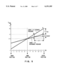
- the values of the Curve 3 shown in FIG. 7 are stored in the memory 17 before the shipment of the hard disk drive device. These values of the Curve 3 are obtained by measuring the current I VCM applied to the VCM 11 for keeping the head 9 at the cylinder position 12 and calculating the difference value ⁇ I VCM F , in the manner as described before, when the atmospheric pressure is decreased from the reference atmospheric pressure on the ground to an expected lowest pressure.
- the values of the atmospheric pressure and the value of ⁇ I VCM on the Curve 3 are stored in the memory 17 as the conversion table.
- a threshold value P TH of the atmospheric pressure is established, as shown in FIG. 7.
- the pressure is equal to the threshold value P TH .
- the threshold value P TH indicates the value for inhibiting the error recovery operation. If a pressure corresponding to the detected difference value ⁇ I VCM is smaller than the threshold value P TH , the error recovery process should be inhibited.
- the reasons for inhibiting the error recovery process is that at the pressure lower than the threshold value P TH , the risk of the sticking of the head/slider assembly 7 onto the surface of the magnetic recording disk 1 is increased.
- ⁇ I VCM representing the difference between the value of the Curve 2 and the value of the Curve 1 at the cylinder position "12"
- a slope or inclination of the Curve 2 can be compared with the slope of the Curve 1.
- a triangle defined by three points A, B and C, and a triangle defined by three points C, D and E are shown.
- the length between the points B and C and the length between the points D and E are equal to ⁇ X.
- the length between the points C and E is called as ⁇ VCMREF .
- the slope K of the Curve 2 is represented by the following expression.
- the slope K REF of the Curve 1 is represented by the following formula.
- the detected atmospheric pressure is equal to the reference atmospheric pressure on the ground.
- the atmospheric pressure is equal to the threshold value P TH at K REF + ⁇ and the value of K is compared with the value of the K REF + ⁇ .
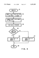
- FIG. 8 shows a flow chart of the operation of the hard disk drive device performed during the POR period in accordance with the present invention.
- a block 81 the POR period is started; and the main control circuit 16 of the hard disk drive device is informed of the start of the POR by CPU of the personal computer.
- the operation proceeds to a block 82 in which the main control circuit 16 detects the increased currents to the VCM 11 at each cylinder position "0", “1", “2”, “3”, “6", "10", "11” and “12” of the disk 1; and stores these values as the Curve 2 in the memory 17.
- the operation proceeds to a block 83 in which the main control circuit 16 compares the value of the Curve 2 with the value of the Curve 1 at the cylinder position 12, and finds out the value ⁇ I VCM which represents the difference between the value of the Curve 2 and the value of the Curve 1 at the cylinder position 12. The operation then proceeds to a block 84 in which the main control circuit 16 finds out the value of the actual atmospheric pressure from the difference value ⁇ I VCM based upon the Curve 3 shown in FIG. 7. The operation proceeds to a block 85 in which the main control circuit 16 determines whether the detected value of the actual atmospheric pressure is lower than the threshold value P TH shown in FIG. 7.
- the information such as Flag 1 or Flag 0, indicating whether the detected value of the atmospheric pressure is lower than the threshold value P TH or not, is stored in the memory 17 during the POR period. If the detected value of the actual atmospheric pressure is lower than the threshold value P TH , the information, such as the Flag 1, is stored in the memory 17 in the block 86. If the detected value of the atmospheric pressure is larger than the threshold value P TH , the information, such as the Flag 0, indicating this status stored in the memory 17 in the block 87. The operation performed during the POR is terminated in the block 88.
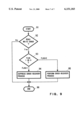
- the main control circuit 16 performs the operations of the blocks 91 through 96 shown in FIG. 9. The operation is started in the block 91 and proceeds to the block 92 in which the main control circuit 16 determines whether the read/write error is detected. If the answer of the block 92 is NO, the operation proceeds to the block 96, in which the operation is terminated. If the answer of the block 92 is YES, the operation proceeds to the block 93, in which the flag stored in the memory 17 is determined.
- the operation proceeds to the block 94 in which the error recovery operation is inhibited, and the operation is terminated in the block 96. If the flag is equal to "0", that is the detected value of the atmospheric pressure is higher than the threshold value P TH , the operation proceeds to the block 95 in which the error recovery operation is performed, and the operation is terminated in the block 96.
- the present invention solves the problem found by the inventors of the present invention that the sticking of the head/slider assembly 7 to the surface of the magnetic recording disk 1 tends to occur when the hard disk drive device starts the error recovery mode when the personal computer having this hard disk drive device is used in an airplane flying at a high altitude or in an atmosphere of a high temperature causing the buoyancy of the air bearing to be decreased.
Landscapes
- Recording Or Reproducing By Magnetic Means (AREA)
- Digital Magnetic Recording (AREA)
Abstract
Description
F.sub.RETURN =F1+F2=F1+F.sub.DRAG cos θ
K=ΔI.sub.VCM /ΔX
K.sub.REF =ΔI.sub.VCMREF /ΔX
Claims (7)
Applications Claiming Priority (2)
| Application Number | Priority Date | Filing Date | Title |
|---|---|---|---|
| JP9-128539 | 1997-05-19 | ||
| JP9128539A JP2983009B2 (en) | 1997-05-19 | 1997-05-19 | Disk drive device and control method therefor |
Publications (1)
| Publication Number | Publication Date |
|---|---|
| US6151183A true US6151183A (en) | 2000-11-21 |
Family
ID=14987266
Family Applications (1)
| Application Number | Title | Priority Date | Filing Date |
|---|---|---|---|
| US09/079,876 Expired - Lifetime US6151183A (en) | 1997-05-19 | 1998-05-15 | Disk drive device and method for controlling the same |
Country Status (2)
| Country | Link |
|---|---|
| US (1) | US6151183A (en) |
| JP (1) | JP2983009B2 (en) |
Cited By (8)
| Publication number | Priority date | Publication date | Assignee | Title |
|---|---|---|---|---|
| US20040264028A1 (en) * | 2003-05-13 | 2004-12-30 | Hitachi Global Storage Technologies Japan, Ltd. | Magnetic disk drive and method for controlling the same |
| US20050128623A1 (en) * | 2003-12-15 | 2005-06-16 | Lum Cheewai | Environmental stress protection scheme for a data storage device |
| US20080221789A1 (en) * | 2007-03-09 | 2008-09-11 | Denso Corporation | Navigation apparatus for vehicle |
| US7630157B1 (en) * | 2006-04-13 | 2009-12-08 | Honda Motor Co., Ltd. | Method of selecting an audio source |
| US20100002328A1 (en) * | 2008-07-02 | 2010-01-07 | Kabushiki Kaisha Toshiba | Disk drive in which the dynamic flying height of head is adjusted |
| US7760462B2 (en) | 2008-03-18 | 2010-07-20 | Toshiba Storage Device Corporation | Method of controlling flying height of head slider and information storage apparatus |
| US20100284106A1 (en) * | 2008-01-10 | 2010-11-11 | Pioneer Corporation | Navigation apparatus, operation control apparatus, operation control method, operation control program |
| US20130003216A1 (en) * | 2011-06-30 | 2013-01-03 | Kabushiki Kaisha Toshiba | Head controller, memory device and head control method |
Families Citing this family (3)
| Publication number | Priority date | Publication date | Assignee | Title |
|---|---|---|---|---|
| KR100761841B1 (en) | 2006-04-04 | 2007-09-28 | 삼성전자주식회사 | Apparatus and method for controlling flight height of magnetic head in retry mode and disk drive using same |
| JP2009110614A (en) * | 2007-10-31 | 2009-05-21 | Fujitsu Ltd | Magnetic disk drive and magnetic disk drive control method |
| JP2009289345A (en) | 2008-05-29 | 2009-12-10 | Fujitsu Ltd | Flying height control method, circuit, and information recording device |
Citations (4)
| Publication number | Priority date | Publication date | Assignee | Title |
|---|---|---|---|---|
| US5206570A (en) * | 1991-03-19 | 1993-04-27 | Maxtor Corporation | Actuator servo compensation method |
| US5319509A (en) * | 1990-10-12 | 1994-06-07 | Servo Track Writer Corporation | Method and apparatus for controlling and analyzing a data storage system |
| US5377058A (en) * | 1992-12-31 | 1994-12-27 | International Business Machines Corporation | Fly height servo control of read/write head suspension |
| US5764430A (en) * | 1996-04-01 | 1998-06-09 | International Business Machines Corporation | Disk drive having optimized spindle speed for environment |
-
1997
- 1997-05-19 JP JP9128539A patent/JP2983009B2/en not_active Expired - Fee Related
-
1998
- 1998-05-15 US US09/079,876 patent/US6151183A/en not_active Expired - Lifetime
Patent Citations (4)
| Publication number | Priority date | Publication date | Assignee | Title |
|---|---|---|---|---|
| US5319509A (en) * | 1990-10-12 | 1994-06-07 | Servo Track Writer Corporation | Method and apparatus for controlling and analyzing a data storage system |
| US5206570A (en) * | 1991-03-19 | 1993-04-27 | Maxtor Corporation | Actuator servo compensation method |
| US5377058A (en) * | 1992-12-31 | 1994-12-27 | International Business Machines Corporation | Fly height servo control of read/write head suspension |
| US5764430A (en) * | 1996-04-01 | 1998-06-09 | International Business Machines Corporation | Disk drive having optimized spindle speed for environment |
Cited By (13)
| Publication number | Priority date | Publication date | Assignee | Title |
|---|---|---|---|---|
| US20040264028A1 (en) * | 2003-05-13 | 2004-12-30 | Hitachi Global Storage Technologies Japan, Ltd. | Magnetic disk drive and method for controlling the same |
| US7079348B2 (en) * | 2003-05-13 | 2006-07-18 | Hitachi Global Storage Technologies Japan, Ltd. | Magnetic disk drive operating under a low-pressure environment and controlling the same |
| US20050128623A1 (en) * | 2003-12-15 | 2005-06-16 | Lum Cheewai | Environmental stress protection scheme for a data storage device |
| US7130138B2 (en) * | 2003-12-15 | 2006-10-31 | Seagate Technology Llc | Environmental stress protection scheme for a data storage device |
| US7630157B1 (en) * | 2006-04-13 | 2009-12-08 | Honda Motor Co., Ltd. | Method of selecting an audio source |
| US20080221789A1 (en) * | 2007-03-09 | 2008-09-11 | Denso Corporation | Navigation apparatus for vehicle |
| US8112221B2 (en) * | 2007-03-09 | 2012-02-07 | Denso Corporation | Navigation apparatus for vehicle |
| US20100284106A1 (en) * | 2008-01-10 | 2010-11-11 | Pioneer Corporation | Navigation apparatus, operation control apparatus, operation control method, operation control program |
| US8107184B2 (en) * | 2008-01-10 | 2012-01-31 | Pioneer Corporation | Operation control apparatus, operation control method, operation control program controlling operation of magnetic disc device |
| US7760462B2 (en) | 2008-03-18 | 2010-07-20 | Toshiba Storage Device Corporation | Method of controlling flying height of head slider and information storage apparatus |
| US7706098B2 (en) | 2008-07-02 | 2010-04-27 | Kabushiki Kaisha Toshiba | Disk drive in which the dynamic flying height of head is adjusted |
| US20100002328A1 (en) * | 2008-07-02 | 2010-01-07 | Kabushiki Kaisha Toshiba | Disk drive in which the dynamic flying height of head is adjusted |
| US20130003216A1 (en) * | 2011-06-30 | 2013-01-03 | Kabushiki Kaisha Toshiba | Head controller, memory device and head control method |
Also Published As
| Publication number | Publication date |
|---|---|
| JP2983009B2 (en) | 1999-11-29 |
| JPH10334626A (en) | 1998-12-18 |
Similar Documents
| Publication | Publication Date | Title |
|---|---|---|
| US6151183A (en) | Disk drive device and method for controlling the same | |
| US5341260A (en) | Reduced torque unloading ramp system for a hard disk drive | |
| US6594102B1 (en) | Apparatus and method for retracting the head on power down in a disk drive | |
| US7715145B2 (en) | Variable spindle speed for ramp unload | |
| EP0227845A1 (en) | Method and apparatus for controlling the flying height of the head in a magnetic storage unit | |
| US6920007B2 (en) | Load/unload method and a magnetic disk drive using the method | |
| US6377417B1 (en) | Method for controlling repeatable runout compensation algorithm | |
| JP3085901B2 (en) | Magnetic disk drive and seek control method applied to the same | |
| JP2009157987A (en) | Method for adjusting recess amount of head slider and disk drive device | |
| JP2002525776A (en) | Concentric spacing of virtual data tracks using run-out compensation | |
| JP4131950B2 (en) | Rotating disk storage device | |
| US6977794B1 (en) | Asymmetric seek velocity profile to improve power failure reliability for rigid disk drive with ramp | |
| US7193805B1 (en) | Flying-type disk drive slider with micropad | |
| US6680811B2 (en) | System and method for enhancing load/unload performance of low-flying heads in a disk drive | |
| EP1950741A2 (en) | Device for control of the flying height of magnetic head in a hard disk drive apparatus and a control method therefor | |
| US7158328B2 (en) | Multi-phase acceleration of a data storage disc | |
| US6157509A (en) | Extending actuator range through magnetic flux reversal detection | |
| JP2001034929A (en) | Magnetic disk and magnetic disk drive | |
| US20040075934A1 (en) | Apparatus and method for retracting an actuator | |
| US6882495B2 (en) | Wear reduction of a disc surface using an adaptive dither process | |
| JPH05303842A (en) | Mangetic disk device | |
| JPS634273B2 (en) | ||
| US7570449B2 (en) | Retract control method of HDD and HDD using the same | |
| JP4146088B2 (en) | Flexure with improved lift in the disk drive | |
| JP2658447B2 (en) | Slider loading method |
Legal Events
| Date | Code | Title | Description |
|---|---|---|---|
| AS | Assignment |
Owner name: INTERNATIONAL BUSINESS MACHINES CORPORATION, NEW Y Free format text: ASSIGNMENT OF ASSIGNORS INTEREST;ASSIGNORS:OGASAWARA, KENJA;SAI, FUMINORI;UENO, SHINJI;AND OTHERS;REEL/FRAME:009334/0816 Effective date: 19980708 |
|
| STCF | Information on status: patent grant |
Free format text: PATENTED CASE |
|
| AS | Assignment |
Owner name: MARIANA HDD B.V., NETHERLANDS Free format text: ASSIGNMENT OF ASSIGNORS INTEREST;ASSIGNOR:INTERNATIONAL BUSINESS MACHINES CORPORATION;REEL/FRAME:013663/0348 Effective date: 20021231 |
|
| AS | Assignment |
Owner name: HITACHI GLOBAL STORAGE TECHNOLOGIES NETHERLANDS B. Free format text: CHANGE OF NAME;ASSIGNOR:MARIANA HDD B.V.;REEL/FRAME:013746/0146 Effective date: 20021231 |
|
| FEPP | Fee payment procedure |
Free format text: PAYOR NUMBER ASSIGNED (ORIGINAL EVENT CODE: ASPN); ENTITY STATUS OF PATENT OWNER: LARGE ENTITY |
|
| FPAY | Fee payment |
Year of fee payment: 4 |
|
| FPAY | Fee payment |
Year of fee payment: 8 |
|
| FPAY | Fee payment |
Year of fee payment: 12 |
|
| AS | Assignment |
Owner name: HGST, NETHERLANDS B.V., NETHERLANDS Free format text: CHANGE OF NAME;ASSIGNOR:HGST, NETHERLANDS B.V.;REEL/FRAME:029341/0777 Effective date: 20120723 Owner name: HGST NETHERLANDS B.V., NETHERLANDS Free format text: CHANGE OF NAME;ASSIGNOR:HITACHI GLOBAL STORAGE TECHNOLOGIES NETHERLANDS B.V.;REEL/FRAME:029341/0777 Effective date: 20120723 |
|
| AS | Assignment |
Owner name: WESTERN DIGITAL TECHNOLOGIES, INC., CALIFORNIA Free format text: ASSIGNMENT OF ASSIGNORS INTEREST;ASSIGNOR:HGST NETHERLANDS B.V.;REEL/FRAME:040818/0551 Effective date: 20160831 |