US6150660A - Staring horizon sensor - Google Patents
Staring horizon sensor Download PDFInfo
- Publication number
- US6150660A US6150660A US09/181,115 US18111598A US6150660A US 6150660 A US6150660 A US 6150660A US 18111598 A US18111598 A US 18111598A US 6150660 A US6150660 A US 6150660A
- Authority
- US
- United States
- Prior art keywords
- horizon
- linear array
- infrared
- staring
- detector means
- Prior art date
- Legal status (The legal status is an assumption and is not a legal conclusion. Google has not performed a legal analysis and makes no representation as to the accuracy of the status listed.)
- Expired - Lifetime
Links
- 230000003252 repetitive effect Effects 0.000 claims abstract description 14
- 238000003491 array Methods 0.000 claims abstract description 12
- 125000004122 cyclic group Chemical group 0.000 claims abstract description 7
- 238000013144 data compression Methods 0.000 claims abstract description 5
- 238000000034 method Methods 0.000 claims description 8
- 230000000737 periodic effect Effects 0.000 claims description 6
- 238000003384 imaging method Methods 0.000 claims description 3
- 238000012545 processing Methods 0.000 abstract description 3
- 229920000535 Tan II Polymers 0.000 description 5
- 238000010586 diagram Methods 0.000 description 5
- 238000001514 detection method Methods 0.000 description 4
- 230000003287 optical effect Effects 0.000 description 3
- 230000003068 static effect Effects 0.000 description 3
- CURLTUGMZLYLDI-UHFFFAOYSA-N Carbon dioxide Chemical compound O=C=O CURLTUGMZLYLDI-UHFFFAOYSA-N 0.000 description 2
- 238000012986 modification Methods 0.000 description 2
- 230000004048 modification Effects 0.000 description 2
- 230000035945 sensitivity Effects 0.000 description 2
- 229910002092 carbon dioxide Inorganic materials 0.000 description 1
- 239000001569 carbon dioxide Substances 0.000 description 1
- 238000013461 design Methods 0.000 description 1
- 230000000694 effects Effects 0.000 description 1
- 230000002708 enhancing effect Effects 0.000 description 1
- 230000002349 favourable effect Effects 0.000 description 1
- 238000005259 measurement Methods 0.000 description 1
- 238000004806 packaging method and process Methods 0.000 description 1
- 230000005855 radiation Effects 0.000 description 1
- 238000005070 sampling Methods 0.000 description 1
Images

Classifications
-
- G—PHYSICS
- G01—MEASURING; TESTING
- G01C—MEASURING DISTANCES, LEVELS OR BEARINGS; SURVEYING; NAVIGATION; GYROSCOPIC INSTRUMENTS; PHOTOGRAMMETRY OR VIDEOGRAMMETRY
- G01C21/00—Navigation; Navigational instruments not provided for in groups G01C1/00 - G01C19/00
- G01C21/02—Navigation; Navigational instruments not provided for in groups G01C1/00 - G01C19/00 by astronomical means
-
- B—PERFORMING OPERATIONS; TRANSPORTING
- B64—AIRCRAFT; AVIATION; COSMONAUTICS
- B64G—COSMONAUTICS; VEHICLES OR EQUIPMENT THEREFOR
- B64G1/00—Cosmonautic vehicles
- B64G1/22—Parts of, or equipment specially adapted for fitting in or to, cosmonautic vehicles
- B64G1/24—Guiding or controlling apparatus, e.g. for attitude control
- B64G1/36—Guiding or controlling apparatus, e.g. for attitude control using sensors, e.g. sun-sensors, horizon sensors
- B64G1/365—Guiding or controlling apparatus, e.g. for attitude control using sensors, e.g. sun-sensors, horizon sensors using horizon or Earth sensors
-
- B—PERFORMING OPERATIONS; TRANSPORTING
- B64—AIRCRAFT; AVIATION; COSMONAUTICS
- B64G—COSMONAUTICS; VEHICLES OR EQUIPMENT THEREFOR
- B64G1/00—Cosmonautic vehicles
- B64G1/22—Parts of, or equipment specially adapted for fitting in or to, cosmonautic vehicles
- B64G1/24—Guiding or controlling apparatus, e.g. for attitude control
- B64G1/36—Guiding or controlling apparatus, e.g. for attitude control using sensors, e.g. sun-sensors, horizon sensors
- B64G1/366—Guiding or controlling apparatus, e.g. for attitude control using sensors, e.g. sun-sensors, horizon sensors using magnetometers
Definitions
- This invention relates to a staring or static type horizon sensor using linear arrays of infrared detectors having the horizon to be detected imaged thereon in which the elements of the array are interconnected in groups of repetitive patterns of alternating polarity whose outputs are processed to provide attitude information.
- the two main categories of horizon sensors are scanning and staring or static types.
- the scanning sensor mechanically scans the image of the earth over an infrared detector whose signal output is used to determine the attitude of the horizon sensor with respect to the earth. These sensors provide good accuracy over a wide angular range but have limited reliability due to moving parts.
- the staring or static type horizon sensor the horizon is imaged onto an infrared detector so that the edge of the earth's image falls in the infrared detector's active area which senses the thermal discontinuity between the relatively warm earth and cold space and uses this information to determine the attitude of the spacecraft on which the sensor is positioned. Since the earth's radiance is non-uniform and unpredictable even in the most favorable optical band due to latitude, season and the weather, the staring sensor causes errors that increase with the angular extent of the earth subtended by the sensor's field-of-view. By dividing the field-of-view into many small sized elements, a simple linear array of infrared detectors offers extended range and higher accuracy than the staring sensor having larger areas and fewer elements.
- the disadvantage of the multidetector linear arrays is the requirement of sampling and processing the signal outputs of each element in the array which requires a multiplicity of electronic switches and processing electronics to convert the output signals to usable information.
- Another object of this invention is to provide a new and improved staring linear array horizon sensor having a smaller number of signal outputs than the number of detectors in the linear array thereby reducing the electronic bandwidth of the sensor, the electronic complexity and enhancing reliability.
- Still another object of this invention is to provide a new and improved staring linear array horizon sensor that minimizes error in the attitude measurement due to the earth thermal variations.
- Yet another object of this invention is to provide a new and improved staring array sensor that maintains the range and accuracy of a simpler array using hard wire interconnections of the elements of the array to provide focal-plane-data compression and to reduce the number of output signals from the array.
- a method of determining the attitude of a spacecraft using a staring array horizon sensor comprises the steps of imaging the horizon on linear array infrared detector means, interconnecting the elements of the linear array infrared detector means in repetitive cycles of alternating polarity patterns, offsetting the phase of said repetitive cyclic alternating polarity patterns of infrared detectors, deriving signal outputs from said patterns of infrared detectors and, quadrature detecting said signal outputs to determine the position of the spacecraft with respect to the horizon.
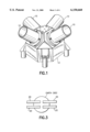
- FIG. 1 is a side elevational view of an illustrative embodiment of a horizon sensor utilizing the present invention using four telescopes.
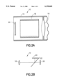
- FIG. 2A is a longitudinal cross-sectional view of one type of telescope that may be used in FIG. 1 and
- FIG. 2B is a schematic diagram of another type of telescope incorporating a beamsplitter which may be used.
- FIG. 3 is an illustrative embodiment projecting the field of view patterns on an earth disc using two of the four telescope sensors shown in FIG. 1 in a geosynchrous application.
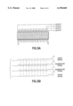
- FIG. 4A is an illustrative schematic embodiment of two linear detector arrays in quadrature.
- FIG. 4B illustrates the output signals vs. the horizon location for the detectors shown in FIG. 4A.
- FIG. 5A illustrates the use of a single array in which the output of the detectors in FIG. 4A are synthesized by interconnecting the detectors as shown.
- FIG. 5B illustrates the waveform of the output of the single array of FIG. 5A.
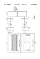
- FIG. 6 is a simplified block diagram for determining an accurate depression angle using one quadrature detector and one coarse detector.
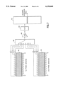
- FIG. 7 is a simplified block diagram for a sensor using two quadrature (phase) detectors with different cycle lengths.
- the horizon sensor in accordance with the present invention comprises one or more telescopes each of which contains one or more detector arrays which are mounted in a satellite or spacecraft.
- FIG. 1 shows an illustrative arrangement using four telescopes mounted in a unitary housing 12 which provides the proper angular orientation of the telescopes 10 and houses the required electronics. While only one telescope is essential for geosynchronous mission or a single axis application at low earth orbit (LEO--approximately 200 km to 5000 km), additional telescopes provide improved accuracy and redundancy in case a telescope is damaged or disabled.
- FIG. 3 illustrates the use of the two telescopes of FIG. 1 which are mounted on the spacecraft with the optical axis of each telescope pointing toward the edge of the earth's disc.
- Each telescope 10 contains two linear detector arrays 20.
- the image of detectors 20 having 2 degree ⁇ 16 degree fields are shown which is a suitable configuration for a geosynchronous altitude sensor.
- the earth's image is shown covering about half the active area of the detector 20 which is known as the "dip-in", or in this example, an 8 degree "dip-in".
- each telescope 10 include a housing 14 which has lens 16 positioned on one end thereof and encloses a linear detector array 20 therein.
- An offset radiation source 18 may also be enclosed by the housing 14.
- the infrared detector array 20 is made up of a plurality of detector elements in form of thermopile detectors.
- the thermocouples provide a wide latitude of geometrical configurations, and accordingly can provide the sensitivity pattern desired particularly since the reference junctions of a thermocouple can be deposited with positive and negative polarity or zero sensitivity.
- other infrared detectors such as thermal, photovoltaic or photoconductive may be used, the thermocouple is preferred because of the flexibility in the design and the multitude of interconnections of individual elements which can be made to form the thermopiles employed in this invention.
- FIG. 2B illustrates a schematic of a telescope 10 using a beam splitter 22.
- each such linear array 20 may be desirable for each such linear array 20 to have the same field of view to increase the accuracy.
- the staring linear array 20 as pointed out is made up of a plurality of small elements of either thermocouples as preferred or by using pattern masks or lenticular arrays over large type detectors.
- thermocouples and connecting the active junctions of the thermocouple together in cyclic, alternating polarity patterns provides a hard-wired, focal plane data compression which reduces the number of output signals and enhances the reliability of the sensor.
- quadrature detection of phase Another aspect of the invention is that by using a second similar detector group offset from the first, their outputs can be combined to accurately determine the horizon position with respect to the periodic structure of the pair, referred to as quadrature detection of phase, and herein is called a quadrature detector. Since this method only determines the relative position of the horizon within the periodic cycle of the detector, the absolute position is still required to be determined. In one implementation, two, or more, quadrature detectors with different spatial periods are combined to determine the absolute horizon position. In another implementation, a traditional, coarse, staring sensor is used to determine the position to the nearest periodic cycle. The additional detectors could be combined into a single sensor package utilizing a single telescope or could use multiple telescopes or separate packages or some combination of these packaging methods.
- attitude-mode Global Positioning Sensor GPS
- magnetometer a magnetometer
- the invention is not limited to the use of these sensors.
- FIG. 4A While many detector configurations can be contrived to generate the required signals and quadrature detection, an illustrative example is shown in FIG. 4A in which two arrays in quadrature, designated "A" and "B", as comprised of a number of elements connected as shown. Detectors A and B are identical with the same cyclic pattern which is shifted to the right in detector B. The "A” and “B” outputs as the horizon of the earth crosses these detectors is shown in FIG. 4B. The phase angle within a cycle is determined by the relative outputs "A" to "B". The "A" and “B” outputs can also be synthesized using a single array connected as shown in FIG. 5A.
- FIGS. 6 and 7 Two examples of illustrative embodiments are shown in FIGS. 6 and 7 although many different detector configurations and combinations may be employed to determine the satellite attitude.
- FIG. 6 shows a simplified block diagram for determining an accurate depression angle using one quadrature phase detector 24 and one coarse detector 34.
- the coarse detector 34 could be in the same envelope as the quadrature detector or it could be in a separate co-aligned sensor.
- Phase detector 24 has its a, b, c, d outputs coupled to switching network 26 from which they are applied to amplifier 28 and fed to an A/D converter 30.
- Coarse detector 34 has its outputs, which include an earth reference A and a space reference S, applied to switching network 36, and then amplified by amplifier 38 and applied to A/D converter 40. Separate electronic channels are used for the two detectors although they could be combined.
- the outputs of the coarse and quadrature (phase) detector are fed to a single processor 32 which uses both of these outputs to generate an accurate depression angle.
- a tan 2 is the four-quadrant arctangent function with output in degrees
- H is the cycle length of the quadrature detector (in degrees).
- H A is the height of the A field (in degrees);
- K B and K A are calibration constants.
- n is an integer number ranging from 0 to one less than the number of cycles in the quadrature detector which minimizes the expression abs(X-Xc).
- abs is the absolute value function.
- FIG. 7 shows a simplified block diagram for a sensor using two quadrature (or phase) detectors 42 and 44 with different cycle lengths, H1 and H2.
- the cycle lengths are chosen so that there is no repeat of combined phases within the overall length of the detector.
- the 2nd detector 44 uses nine cycles to subtend the same angle as the first detector 42 does using ten cycles.
- the outputs of the detectors 42 and 44 are applied to switching network 46, amplifier 48, A/D converter 5 and processor 52.
- a tan 2 is the four-quadrant arctangent function with output in degrees
- H1 and H2 are the cycle lengths of the respective quadrature detectors (in degrees).
- n is an integer number ranging from 0 to one less than the number of cycles in the 1st quadrature detector and m is a number ranging from 0 to one less than the number of cycles in the 2nd quadrature detector which minimizes the expression: abs (X1-X2). ("abs" is the absolute value function.)
- this new concept in horizon sensing utilizes small sized detectors interconnected in repetitive, cyclic patterns which are shifted in phrase to enable quadrature detection.
- the quadrature detection normalizes the non-uniformity of radiance on different parts of the earth's disc.
- the detectors can be interlaced, superimposed, radially or longitudinally displaced to view similar radiance levels.
- the large number of small detector elements allows many configurations and combinations which can be used and tailored to a specific application.
Landscapes
- Engineering & Computer Science (AREA)
- Remote Sensing (AREA)
- Radar, Positioning & Navigation (AREA)
- Physics & Mathematics (AREA)
- Environmental & Geological Engineering (AREA)
- Automation & Control Theory (AREA)
- General Physics & Mathematics (AREA)
- Life Sciences & Earth Sciences (AREA)
- Astronomy & Astrophysics (AREA)
- General Life Sciences & Earth Sciences (AREA)
- Geochemistry & Mineralogy (AREA)
- Geology (AREA)
- Chemical & Material Sciences (AREA)
- Combustion & Propulsion (AREA)
- Aviation & Aerospace Engineering (AREA)
- Navigation (AREA)
Abstract
Description
A=a-b-c;
B=b-c+d.
A=a-b-c;
B=b-c+d.
Theta=a tan 2(A,B)×H/360°;
Xc=H.sub.A ×(B2-K.sub.B S2)/(A2-K.sub.A S2);
X=nH+Theta;
A1=a1-b1-c1,
B1=b1-c1+d1;
A2=a2-b2-c2;
B2=b2-c2+d2.
Theta 1=a tan 2(A1,B1)×H1/360°;
Theta 2=a tan 2(A2,B2)×H2/360°;
X=(X1+X2)/2;
X1=nH1+Theta1;
X2=mH2+Theta2;
Claims (9)
Priority Applications (1)
| Application Number | Priority Date | Filing Date | Title |
|---|---|---|---|
| US09/181,115 US6150660A (en) | 1998-10-28 | 1998-10-28 | Staring horizon sensor |
Applications Claiming Priority (1)
| Application Number | Priority Date | Filing Date | Title |
|---|---|---|---|
| US09/181,115 US6150660A (en) | 1998-10-28 | 1998-10-28 | Staring horizon sensor |
Publications (1)
| Publication Number | Publication Date |
|---|---|
| US6150660A true US6150660A (en) | 2000-11-21 |
Family
ID=22662964
Family Applications (1)
| Application Number | Title | Priority Date | Filing Date |
|---|---|---|---|
| US09/181,115 Expired - Lifetime US6150660A (en) | 1998-10-28 | 1998-10-28 | Staring horizon sensor |
Country Status (1)
| Country | Link |
|---|---|
| US (1) | US6150660A (en) |
Cited By (3)
| Publication number | Priority date | Publication date | Assignee | Title |
|---|---|---|---|---|
| US20110004405A1 (en) * | 2009-07-01 | 2011-01-06 | Optical Physics Company Inc. | Earth horizon sensor |
| CN105116910A (en) * | 2015-09-21 | 2015-12-02 | 中国人民解放军国防科学技术大学 | Satellite attitude control method for ground point staring imaging |
| CN106017456A (en) * | 2016-05-05 | 2016-10-12 | 中国人民解放军国防科学技术大学 | Analytic solution method for ground point staring satellite expectation angular speed |
Citations (12)
| Publication number | Priority date | Publication date | Assignee | Title |
|---|---|---|---|---|
| US3936629A (en) * | 1974-10-07 | 1976-02-03 | U.S. Philips Corporation | Horizon sensor for a satellite in geostationary orbit |
| US4785169A (en) * | 1986-12-09 | 1988-11-15 | Barnes Engineering Company | Method of correcting errors in horizon sensors caused by radiance variations |
| US4794245A (en) * | 1987-03-03 | 1988-12-27 | Applied Research Corporation | Position sensor |
| US5055689A (en) * | 1990-01-26 | 1991-10-08 | Quantic Industries, Inc. | Horizon sensor apparatus and method therefor |
| US5079419A (en) * | 1990-06-06 | 1992-01-07 | Edo Corporation, Barnes Engineering Div. | Horizon sensor compensation for radiance variations |
| US5399862A (en) * | 1993-05-18 | 1995-03-21 | Edo Corporation, Barnes Engineering Division | Method for reducing radiance errors in earth sensors |
| US5477052A (en) * | 1994-04-18 | 1995-12-19 | Servo Corporation Of America | Earth sensor for satellites with radiance compensation |
| US5585633A (en) * | 1994-08-16 | 1996-12-17 | Matra Marconi Space France | Terrestrial sensor device for satellite or the like |
| US5646723A (en) * | 1995-03-13 | 1997-07-08 | Space Sciences Corporation | Combined earth sensor |
| US5721431A (en) * | 1996-09-17 | 1998-02-24 | Institute For Space And Terrestrial Science | Satellite attitude sensor using thermal imaging |
| US5744801A (en) * | 1995-11-03 | 1998-04-28 | Servo Corporation Of America | Earth horizon sensor with staggered array of sensors |
| US5903007A (en) * | 1997-07-28 | 1999-05-11 | Edo Corporation, Barnes Engineering Division | Method and apparatus compensating for radiance variations in horizon sensing |
-
1998
- 1998-10-28 US US09/181,115 patent/US6150660A/en not_active Expired - Lifetime
Patent Citations (12)
| Publication number | Priority date | Publication date | Assignee | Title |
|---|---|---|---|---|
| US3936629A (en) * | 1974-10-07 | 1976-02-03 | U.S. Philips Corporation | Horizon sensor for a satellite in geostationary orbit |
| US4785169A (en) * | 1986-12-09 | 1988-11-15 | Barnes Engineering Company | Method of correcting errors in horizon sensors caused by radiance variations |
| US4794245A (en) * | 1987-03-03 | 1988-12-27 | Applied Research Corporation | Position sensor |
| US5055689A (en) * | 1990-01-26 | 1991-10-08 | Quantic Industries, Inc. | Horizon sensor apparatus and method therefor |
| US5079419A (en) * | 1990-06-06 | 1992-01-07 | Edo Corporation, Barnes Engineering Div. | Horizon sensor compensation for radiance variations |
| US5399862A (en) * | 1993-05-18 | 1995-03-21 | Edo Corporation, Barnes Engineering Division | Method for reducing radiance errors in earth sensors |
| US5477052A (en) * | 1994-04-18 | 1995-12-19 | Servo Corporation Of America | Earth sensor for satellites with radiance compensation |
| US5585633A (en) * | 1994-08-16 | 1996-12-17 | Matra Marconi Space France | Terrestrial sensor device for satellite or the like |
| US5646723A (en) * | 1995-03-13 | 1997-07-08 | Space Sciences Corporation | Combined earth sensor |
| US5744801A (en) * | 1995-11-03 | 1998-04-28 | Servo Corporation Of America | Earth horizon sensor with staggered array of sensors |
| US5721431A (en) * | 1996-09-17 | 1998-02-24 | Institute For Space And Terrestrial Science | Satellite attitude sensor using thermal imaging |
| US5903007A (en) * | 1997-07-28 | 1999-05-11 | Edo Corporation, Barnes Engineering Division | Method and apparatus compensating for radiance variations in horizon sensing |
Cited By (4)
| Publication number | Priority date | Publication date | Assignee | Title |
|---|---|---|---|---|
| US20110004405A1 (en) * | 2009-07-01 | 2011-01-06 | Optical Physics Company Inc. | Earth horizon sensor |
| CN105116910A (en) * | 2015-09-21 | 2015-12-02 | 中国人民解放军国防科学技术大学 | Satellite attitude control method for ground point staring imaging |
| CN106017456A (en) * | 2016-05-05 | 2016-10-12 | 中国人民解放军国防科学技术大学 | Analytic solution method for ground point staring satellite expectation angular speed |
| CN106017456B (en) * | 2016-05-05 | 2017-03-29 | 中国人民解放军国防科学技术大学 | A kind of satellite stared to ground point expects angular velocity Analytical Solution method |
Similar Documents
| Publication | Publication Date | Title |
|---|---|---|
| Mather | The cosmic background explorer (COBE) | |
| Oxley et al. | The EBEX experiment | |
| US20110004405A1 (en) | Earth horizon sensor | |
| Cofield et al. | Design and field-of-view calibration of 114-660-GHz optics of the Earth observing system microwave limb sounder | |
| US9297880B2 (en) | Two axis interferometer tracking device and method | |
| US6150660A (en) | Staring horizon sensor | |
| Liebe et al. | Three-axis sun sensor for attitude determination | |
| Niinuma et al. | Astrometry of H2O masers in the massive star-forming region IRAS 06061+ 2151 with VERA | |
| US9322911B1 (en) | Passive phased array imager using sub-phase sampling CMOS detectors and a smart ROIC | |
| Bailey et al. | Fan-beam observations of radio sources at 408 and 1407 MHz | |
| Graham et al. | The performance and scientific rationale for an infrared imaging Fourier transform spectrograph on a large space telescope | |
| Palchetti et al. | Design and mathematical modelling of the space-borne far-infrared Fourier transform spectrometer for REFIR experiment | |
| JP2014058176A (en) | Earth sensor and earth edge detection method using earth sensor | |
| JPH0626857A (en) | Solar sensor for z-axis | |
| CN112683198A (en) | Three-degree-of-freedom angle photoelectric measuring device and measuring method thereof | |
| JP2560475B2 (en) | Antenna angle detector | |
| McAlister | Speckle interferometry as a method for detecting nearby extrasolar planets | |
| Imai et al. | Multiple Outflows Traced by H2O Masers around the Ultra-Compact H II Region G 34.26+ 0.15 | |
| Kuze et al. | On-orbit performance and level 1 data processing of TANSO-FTS and CAI on GOSAT | |
| Rodriguez et al. | Centimetric sea surface height accuracy using the wide-swath ocean altimeter | |
| US12436033B2 (en) | Apparatus and method to measure direction and polarization of electromagnetic waves | |
| Marchese et al. | A compact lightweight earth horizon sensor using an uncooled infrared bolometer | |
| Navia et al. | Search for anisotropic light propagation as a function of laser beam alignment relative to the Earth's velocity vector | |
| Cetinic et al. | PACE OCI Calibration and Geolocation Operational Algorithm Description | |
| Jalink et al. | Conceptual design and analysis of an infrared horizon sensor with compensation for atmospheric variability |
Legal Events
| Date | Code | Title | Description |
|---|---|---|---|
| AS | Assignment |
Owner name: EDO CORPORATION, BARNES ENGINEERING DIVISION, CONN Free format text: ASSIGNMENT OF ASSIGNORS INTEREST;ASSIGNOR:SAVOCA, ROBERT C.;REEL/FRAME:009815/0611 Effective date: 19981027 |
|
| STCF | Information on status: patent grant |
Free format text: PATENTED CASE |
|
| AS | Assignment |
Owner name: GOODRICH CORPORATION, NORTH CAROLINA Free format text: ASSIGNMENT OF ASSIGNORS INTEREST;ASSIGNOR:JETTE, PAUL C.;REEL/FRAME:013231/0504 Effective date: 20021014 |
|
| AS | Assignment |
Owner name: GOODRICH CORPORATION, NORTH CAROLINA Free format text: ASSIGNMENT OF ASSIGNORS INTEREST;ASSIGNOR:EDO CORPORATION, BARNES ENGINEERING DIVISION;REEL/FRAME:013845/0777 Effective date: 20030729 |
|
| FEPP | Fee payment procedure |
Free format text: PAYOR NUMBER ASSIGNED (ORIGINAL EVENT CODE: ASPN); ENTITY STATUS OF PATENT OWNER: LARGE ENTITY |
|
| FPAY | Fee payment |
Year of fee payment: 4 |
|
| FPAY | Fee payment |
Year of fee payment: 8 |
|
| FPAY | Fee payment |
Year of fee payment: 12 |