US6148741A - Table with adjustable table top portions - Google Patents
Table with adjustable table top portions Download PDFInfo
- Publication number
- US6148741A US6148741A US09/193,526 US19352698A US6148741A US 6148741 A US6148741 A US 6148741A US 19352698 A US19352698 A US 19352698A US 6148741 A US6148741 A US 6148741A
- Authority
- US
- United States
- Prior art keywords
- tubular members
- table top
- height
- portions
- movable
- Prior art date
- Legal status (The legal status is an assumption and is not a legal conclusion. Google has not performed a legal analysis and makes no representation as to the accuracy of the status listed.)
- Expired - Fee Related
Links
- 230000007246 mechanism Effects 0.000 claims description 28
- 241001669573 Galeorhinus galeus Species 0.000 claims 1
- 125000006850 spacer group Chemical group 0.000 description 6
- 238000011161 development Methods 0.000 description 3
- 230000018109 developmental process Effects 0.000 description 3
- 230000000717 retained effect Effects 0.000 description 2
Images
Classifications
-
- A—HUMAN NECESSITIES
- A47—FURNITURE; DOMESTIC ARTICLES OR APPLIANCES; COFFEE MILLS; SPICE MILLS; SUCTION CLEANERS IN GENERAL
- A47B—TABLES; DESKS; OFFICE FURNITURE; CABINETS; DRAWERS; GENERAL DETAILS OF FURNITURE
- A47B9/00—Tables with tops of variable height
- A47B9/04—Tables with tops of variable height with vertical spindle
-
- A—HUMAN NECESSITIES
- A47—FURNITURE; DOMESTIC ARTICLES OR APPLIANCES; COFFEE MILLS; SPICE MILLS; SUCTION CLEANERS IN GENERAL
- A47B—TABLES; DESKS; OFFICE FURNITURE; CABINETS; DRAWERS; GENERAL DETAILS OF FURNITURE
- A47B2200/00—General construction of tables or desks
- A47B2200/0001—Tops
- A47B2200/0002—Corner desk
Definitions
- This invention generally relates to the field of furniture pieces and, in particular, tables with height-adjustable table top.
- the tables of the above mentioned kind offer some advantages in terms of comfort and usefullness. As a matter of fact, these tables permit the computer terminal to be integrated in a much more ergonomic manner than the tables having a single table top portion even if adjustable in height and permit the user to organize in a rational manner the working area at his disposal. Nevertheless, these tables have the disadvantage of not permitting a separate height-adjustment of the two table top portions precisely because these two portions have a fixed position. Therefore, the user cannot completely adapt the table to his comfort requirements.
- the present invention is aimed at obviating this disadvantage by providing a table provided with a height-adjustable table top formed of two portions which permits, apart from an adjustment in height of the table top portion acting as working surface, an height-adjustment of the portion acting as a support for objects which require to be located in a more convenient position in terms of functionality, as for example a desktop computer.
- the table according to the present invention is of the kind having a table top formed of two portions, one intended for use as a working surface and the other for use as an additional supporting surface, and at least one vertical member for supporting the table top, and is characterized in that:
- the table top portions intended for use as a working surface and as an additional supporting surface, respectively, are adjustable in height conjointly or separately, and
- the vertical support member for supporting the table top comprises:
- tubular members arranged one into the other so as to be axially movable relative to each other, one of said tubular members being stationary and adapted to rest onto the ground and the other being movable and directly or indirectly connected to the table top portion intended for use as a working surface and/or to the table top portion intended for use as an additional supporting surface,
- control means adapted to operate the drive means in order to permit the user to perform a conjoint height-adjustment of the two table top portions or a separate height-adjustment of one of the two table top portions relative to the other.
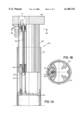
- FIGS. 1A and 1B show a longitudinal sectional view and a transverse sectional view taken along line 1B--1B of FIG. 1A, respectively, of a first vertical support member for supporting a table top according to the invention
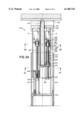
- FIGS. 2A, 2B and 2C show a longitudinal sectional view, a transverse sectional view taken along line 2B--2B of FIG. 2A and a transverse sectional view taken along line 2C--2C of FIG. 2A, respectively, of a second vertical support member for supporting the table top according to the invention, and
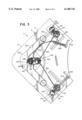
- FIG. 3 is a cross-sectional plane bottom view of the height-adjustable table according to the invention with a table top formed of two portions one of which is supported by two vertical support members as described with reference to FIGS. 1A and 1B and the other is supported by a third vertical support member as described with reference to FIGS. 2A, 2B and 2C.
- table leg generally designates a vertical support member of the table top according to the present invention and will be described in two preferred embodiments thereof.
- the leg generally designated by 100, is formed of two vertical tubular members 101 and 102 arranged one into the other so as to be reciprocally movable in the axial direction.
- the tubular member 101 is fixed. Its lower end portion is closed by a bordered plate 103 acting also as supporting base for the leg 100, whereas its upper end portion is open and the tubular member 102 projects therefrom.
- the tubular member 102 is movable along the axial direction. Its lower end portion has an aperture, whereas its upper end portion is connected to a support and connecting plate 104.
- the drive mechanism for the vertical motion of the tubular member 102 is formed of a vertical lead screw 105 which is rotated in a nut screw 106 inserted in upper end portion of a vertical tube 107 attached to the bordered plate 103.
- the lead screw 105 is provided with a stop 108 at its lower end portion for preventing it to be removed from the tube 107 and with an unthreaded portion 109 and an hexagonal head 110 at the upper end portion.
- the unthreaded portion 109 of the lead screw 105 is rotatably supported by a plain bearing 111 arranged in a support 112 which is connected to the tubular member 102.
- the plain bearing 111 is retained around the unthreaded portion 109 from below by means of a first spacer 113 and from above by means of a second spacer 114, a washer 115 and finally a retaining ring 116.
- a thrust bearing 117 is interposed between the plain bearing 111 and the spacer 113.
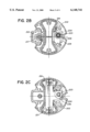
- a driving gear 118 (see FIG. 3) with orthogonally intersecting axes is provided in a housing R in the support and connecting plate 104.
- the driven wheel of the driving gear 118 is coupled to the hexagonal head of the lead screw 105.
- FIGS. 2A, 2B and 2C show a longitudinal sectional view and a cross sectional view taken along two different lines 2B--2B and 2C--2C, respectively, of a second embodiment of table leg.
- all the parts corresponding in configuration and function to parts of the first embodiment of the table leg are designated by the same numeral increased by one hundred.
- the table leg is formed of three vertical tubular members 201, 202 and 219 instead of two as in the first embodiment. These vertical members 201, 202 and 219 are arranged one into the other so as to be reciprocally movable in the axial direction.
- the upper end portion of the tubular member 202 is connected to a support member 220.
- This support member 220 has an opening 221 through which the tubular member 219 can extend.
- a support and connecting plate 222 is connected to the upper end portion of the tubular member 219.
- the table leg 200 embodies two drive mechanisms instead of only one, because in this case there are two tubular elements which are movable in the axial direction, namely the tubular member 202 and the tubular member 219.
- the first drive mechanism which is substantially similar to that embodied in the table leg 100, is formed of a vertical lead screw 205 and a nut screw 206, and is intended for the vertical motion of the tubular element 202.
- a driving gear 218 (see FIG. 3) with orthogonally intersecting axes is provided in a housing R in the tubular member 202.
- the driven wheel of the driving gear 218 is coupled to the hexagonal head 210 of the lead screw 205.
- the second drive mechanism is formed of a vertical lead screw 223 and a nut screw 224 and is intended for the vertical motion of the tubular member 219.
- the lead screw 223 comprises a unthreaded portion 225 and an hexagonal head 226 in the upper end portion.
- the unthreaded portion 225 and the hexagonal head 226 are separated by a short threaded portion 227.
- the unthreaded portion 225 is rotatably mounted in a plain bearing 228 which is housed in a support element 229 connected to the tubular element 202.
- the plain bearing 228 is retained around the unthreaded portion 225 of the lead screw 223 from below by means of a washer 230 and a first spacer 231 and from above by means of a second spacer 232 which is pressed against the plain bearing 228 by means of a pair of nuts 233 screwed onto the short threaded portion 227 of the lead screw 223.
- a thrust bearing 234 is interposed between the plain bearing 228 and the spacer 231.
- the lead screw 223 comprises a unthreaded portion 235 which is rotatably supported by a support 236 connected to the tubular member 202.
- the nut screw 224 is connected to the lower end portion of the tubular member 219 by means of a support member 237.
- a driving gear 238 (see FIG. 3) with orthogonally intersecting axes is provided in a housing R inside the tubular member 202.
- the driven wheel of the driving gear 238 is coupled to the hexagonal head 226 of the lead screw 223. Since the nut screw 224 is movable, the rotation of the lead screw will impart a motion to the nut screw 224 together with the tubular member 219.
- the full travel of the nut screw 224 is restricted by a tubular stop in which the lead screw 223 is inserted.
- the tubular stop 239 is pushed up by the nut screw until it abuts the washer 230.
- a table having a top supported by table legs of the kind described above will now be illustrated.
- the table herein described is of the so called “corner” kind because the table top is so formed as to at least partially embrace the user.
- FIG. 3 there is illustrated a plan bottom view of the corner table, generally indicated with T and comprising a table top P formed of two portions A and B, the first of which really acts as a working surface, whereas the second, located at the corner, is typically intended for supporting the video display of a computer terminal or of a desktop computer in an elevated or lowered position with respect to the working surface.
- the table top P is supported by three table legs, two of which are laterally arranged and one of which is center arranged.
- the two lateral table legs are as that designated by 100 in the first embodiment, while the central table leg is as that designated by 200 in the second embodiment.
- the table top portion A is connected to the support member 220 attached to the upper end portion of the tubular element 202 of the central table leg 200, while the table top portion B is connected to the support and connecting plate 222 attached to the tubular element 219 of the central table leg 200.
- the support member 220 is provided with two extensions 240 to the end of which the support and connecting plate 104 connected to the upper end portion of the tubular member 102 of the lateral table leg 100 is fixed.
- FIG. 3 also illustrates the control mechanism used for actuating the screw mechanisms which are embodied in the lateral and central table legs 100 and 200.
- the control mechanism generally indicated by 300, comprises three bevel gearings 301, 302 and 303, two intermediate shafts 304 and 305, an articulated intermediate shaft 306 and two drive shafts 307 and 308.
- the intermediate shafts 304 and 305 transmit motion from the bevel gearing 301 to the bevel gearing 302 and from the latter to the bevel gearing 303 and the drive shafts 307 and 308 are manually operable by the user by means of crank handles 309 and 310, respectively.
- Each of the bevel gearings 301 and 302 is associated with the driving gear 118 of the relevant lateral table leg 100, while the bevel gearing 302 is associated with the driving gear 218 of the central table leg 200.
- the driving gear 238 of the central table leg 200 is instead directly associated with the articulated intermediate shaft 306.
- the drive shafts 307 and 308 are telescoped so that their crank handles 309 and 310 may be kept out of sight during normal use of the table and pulled out from below the table top P when height adjustments thereof are required.
- Operation of the control mechanism 300 is the following.
- the user By operating the handle 309, the user can adjust the height of the table top P as a whole.
- the control mechanism transmits the control motion at the same time to all the table legs 100 and 200 of the table T.
- the handle 310 By rotating the handle 310, the user is capable of adjusting the height of the table top portion B only.
- the control mechanism 300 transmits the control motion to central table leg 200 only.
- the table portion B can be raised or lowered with respect to the table top portion A.
- the configuration of the table legs 100 and 200 and their supports is given only for explanatory purposes and may vary according to the kind of table, and also the configuration of the control mechanism 300 may vary in order to result operatively the most effective.
Landscapes
- Tables And Desks Characterized By Structural Shape (AREA)
- Accommodation For Nursing Or Treatment Tables (AREA)
- Agricultural Machines (AREA)
Abstract
Description
Claims (3)
Applications Claiming Priority (2)
| Application Number | Priority Date | Filing Date | Title |
|---|---|---|---|
| IT97MI002601A IT1296493B1 (en) | 1997-11-21 | 1997-11-21 | CORNER TABLE WITH WORKTOP AND SUPPORT TOP FOR A CALCULATOR OR SIMILAR ADJUSTABLE IN HEIGHT |
| ITMI97A2601 | 1997-11-25 |
Publications (1)
| Publication Number | Publication Date |
|---|---|
| US6148741A true US6148741A (en) | 2000-11-21 |
Family
ID=11378252
Family Applications (1)
| Application Number | Title | Priority Date | Filing Date |
|---|---|---|---|
| US09/193,526 Expired - Fee Related US6148741A (en) | 1997-11-21 | 1998-11-17 | Table with adjustable table top portions |
Country Status (4)
| Country | Link |
|---|---|
| US (1) | US6148741A (en) |
| EP (1) | EP0917840A3 (en) |
| JP (1) | JPH11244054A (en) |
| IT (1) | IT1296493B1 (en) |
Cited By (22)
| Publication number | Priority date | Publication date | Assignee | Title |
|---|---|---|---|---|
| US6263809B1 (en) * | 1999-03-04 | 2001-07-24 | Argo Office B.V. | Height-adjustable support for supporting a table top |
| US6289825B1 (en) * | 2000-03-31 | 2001-09-18 | Dennis L. Long | Adjustment mechanism for workstation |
| US6494150B1 (en) * | 2001-03-02 | 2002-12-17 | Precision Lifts Of Deerfield Beach, Incorporated | Elevating apparatus for visual displays |
| US6536357B1 (en) | 2000-06-01 | 2003-03-25 | Formway Furniture Limited | Height adjustable table |
| US20050109892A1 (en) * | 2003-11-25 | 2005-05-26 | Wieslaw Bober | Compound lift device |
| US6935250B1 (en) * | 2002-10-09 | 2005-08-30 | Baker Manufacturing Company, Inc. | Adjustable height table with multiple legs operable by a single crank |
| US20050274303A1 (en) * | 2004-06-11 | 2005-12-15 | Kurt Scherrer | Height-adjustment device |
| WO2005104679A3 (en) * | 2004-04-16 | 2006-12-21 | Wieslaw Bober | Device for lifting and directing equipment with video and/or audio information |
| US20080009358A1 (en) * | 2006-06-29 | 2008-01-10 | Thomas Cartwright | Pool table leveling system |
| US20080178779A1 (en) * | 2007-01-31 | 2008-07-31 | Michael Agee | Height adjustable table |
| US20080289545A1 (en) * | 2007-05-25 | 2008-11-27 | Unifor S.P.A. | Workstation System and Workstation with Multiple, Adjustable Height, Work Tops |
| US20090101780A1 (en) * | 2007-10-18 | 2009-04-23 | Rbw Industries, Inc. | Flat screen tv bracket for a vehicle |
| US7658359B2 (en) * | 2004-12-17 | 2010-02-09 | Steelcase Development Corporation | Load compensator for height adjustable table |
| US20100126392A1 (en) * | 2008-11-26 | 2010-05-27 | Watson Furniture Group, Inc. | Reconfigurable desk with invertible working surface |
| US20100187380A1 (en) * | 2007-05-31 | 2010-07-29 | Michael Koder | Height adjustable column, in particular for tables |
| US7806490B1 (en) | 2006-07-10 | 2010-10-05 | Importadvantage, Inc. | Panel mounted appliance elevator apparatus |
| US20110041739A1 (en) * | 2008-04-11 | 2011-02-24 | Jan Verweij | Adjusting device |
| US20110225802A1 (en) * | 2007-08-24 | 2011-09-22 | Steen Mandsfelt Eriksen | Assembling arrangement for securing a tubular furniture leg to the top plate of a piece of furniture |
| US9936802B1 (en) | 2015-10-01 | 2018-04-10 | Baker Manufacturing Company, Inc. | Height adjustable table |
| US10524564B1 (en) * | 2018-08-29 | 2020-01-07 | Tct Nanotec Co., Ltd. | Telescopic post for a table |
| US20230029425A1 (en) * | 2021-07-21 | 2023-01-26 | Timotion Technology Co., Ltd. | Lifting table stand |
| US20250213032A1 (en) * | 2022-08-12 | 2025-07-03 | Qidong Vision Mounts Manufacturing Co.,Ltd. | Electric height-adjustable desk |
Families Citing this family (2)
| Publication number | Priority date | Publication date | Assignee | Title |
|---|---|---|---|---|
| IT1319773B1 (en) * | 2000-11-24 | 2003-11-03 | Unifor Spa | ENDLESS SCREW MECHANISM. |
| US20160255950A1 (en) | 2015-03-03 | 2016-09-08 | David Mata Valdes | Ergonomic desk and modular design for collaborative dispositions |
Citations (3)
| Publication number | Priority date | Publication date | Assignee | Title |
|---|---|---|---|---|
| US2368748A (en) * | 1943-02-19 | 1945-02-06 | Hard Mfg Company | Over-bed table |
| US4593874A (en) * | 1984-09-27 | 1986-06-10 | Dunagan Lawrence G | Adjustable legs for desks and furniture |
| US5271320A (en) * | 1991-08-19 | 1993-12-21 | Reneau Raymond P | Workstation having independently movable mast sections |
Family Cites Families (5)
| Publication number | Priority date | Publication date | Assignee | Title |
|---|---|---|---|---|
| DE8128983U1 (en) * | 1981-10-03 | 1982-03-11 | Willy Fleischer Metallwarenfabrik GmbH und Co KG, 4630 Bochum | "HEIGHT-ADJUSTABLE TABLE FOR SCREEN WORKSTATIONS" |
| DE9215960U1 (en) * | 1992-11-24 | 1993-11-25 | Wini Büromöbel Georg Schmidt GmbH & Co. KG, 31863 Coppenbrügge | Office work table |
| WO1994019987A1 (en) * | 1993-03-09 | 1994-09-15 | Furniture Australia Pty Ltd | Ergonomic furniture |
| CA2237691C (en) * | 1995-11-16 | 2002-03-19 | Robert Beck | Modular desk and desk system |
| JP2000500552A (en) * | 1995-11-16 | 2000-01-18 | ハーマン、ミラー、インコーポレイテッド | Support leg leveling device |
-
1997
- 1997-11-21 IT IT97MI002601A patent/IT1296493B1/en active IP Right Grant
-
1998
- 1998-11-10 EP EP98121351A patent/EP0917840A3/en not_active Withdrawn
- 1998-11-17 US US09/193,526 patent/US6148741A/en not_active Expired - Fee Related
- 1998-11-19 JP JP10329170A patent/JPH11244054A/en active Pending
Patent Citations (3)
| Publication number | Priority date | Publication date | Assignee | Title |
|---|---|---|---|---|
| US2368748A (en) * | 1943-02-19 | 1945-02-06 | Hard Mfg Company | Over-bed table |
| US4593874A (en) * | 1984-09-27 | 1986-06-10 | Dunagan Lawrence G | Adjustable legs for desks and furniture |
| US5271320A (en) * | 1991-08-19 | 1993-12-21 | Reneau Raymond P | Workstation having independently movable mast sections |
Cited By (42)
| Publication number | Priority date | Publication date | Assignee | Title |
|---|---|---|---|---|
| US6263809B1 (en) * | 1999-03-04 | 2001-07-24 | Argo Office B.V. | Height-adjustable support for supporting a table top |
| US6289825B1 (en) * | 2000-03-31 | 2001-09-18 | Dennis L. Long | Adjustment mechanism for workstation |
| WO2001074197A1 (en) * | 2000-03-31 | 2001-10-11 | Long Dennis L | Adjustment mechanism for workstation |
| US6536357B1 (en) | 2000-06-01 | 2003-03-25 | Formway Furniture Limited | Height adjustable table |
| US6494150B1 (en) * | 2001-03-02 | 2002-12-17 | Precision Lifts Of Deerfield Beach, Incorporated | Elevating apparatus for visual displays |
| US6935250B1 (en) * | 2002-10-09 | 2005-08-30 | Baker Manufacturing Company, Inc. | Adjustable height table with multiple legs operable by a single crank |
| US20050109892A1 (en) * | 2003-11-25 | 2005-05-26 | Wieslaw Bober | Compound lift device |
| WO2005054110A3 (en) * | 2003-11-25 | 2005-08-18 | Wieslaw Bober | Compound lift device |
| US7044423B2 (en) * | 2003-11-25 | 2006-05-16 | Wieslaw Bober | Compound lift device |
| WO2005104679A3 (en) * | 2004-04-16 | 2006-12-21 | Wieslaw Bober | Device for lifting and directing equipment with video and/or audio information |
| US7574965B2 (en) * | 2004-06-11 | 2009-08-18 | Usm Holding Ag | Height-adjustment device |
| US20050274303A1 (en) * | 2004-06-11 | 2005-12-15 | Kurt Scherrer | Height-adjustment device |
| US9591920B2 (en) | 2004-12-17 | 2017-03-14 | Steelcase Inc. | Load compensator for height adjustable table |
| US10420417B1 (en) | 2004-12-17 | 2019-09-24 | Steelcase Inc. | Load compensator for height adjustable table |
| US10051955B1 (en) | 2004-12-17 | 2018-08-21 | Steelcase Inc. | Load compensator for height adjustable table |
| US7658359B2 (en) * | 2004-12-17 | 2010-02-09 | Steelcase Development Corporation | Load compensator for height adjustable table |
| US9913532B1 (en) | 2004-12-17 | 2018-03-13 | Steelcase Inc. | Load compensator for height adjustable table |
| US9826825B1 (en) | 2004-12-17 | 2017-11-28 | Steelcase Inc. | Load compensator for height adjustable table |
| US20080009358A1 (en) * | 2006-06-29 | 2008-01-10 | Thomas Cartwright | Pool table leveling system |
| US7654911B2 (en) | 2006-06-29 | 2010-02-02 | Thomas Cartwright | Pool table leveling system |
| US7806490B1 (en) | 2006-07-10 | 2010-10-05 | Importadvantage, Inc. | Panel mounted appliance elevator apparatus |
| US7908981B2 (en) * | 2007-01-31 | 2011-03-22 | Michael Agee | Height adjustable table |
| US8256359B1 (en) | 2007-01-31 | 2012-09-04 | Baker Manufacturing Company, Inc. | Height adjustable table |
| US20080178779A1 (en) * | 2007-01-31 | 2008-07-31 | Michael Agee | Height adjustable table |
| US8490555B1 (en) | 2007-01-31 | 2013-07-23 | Baker Manufacturing Company, Inc. | Height adjustable table |
| US20080289545A1 (en) * | 2007-05-25 | 2008-11-27 | Unifor S.P.A. | Workstation System and Workstation with Multiple, Adjustable Height, Work Tops |
| US20100187380A1 (en) * | 2007-05-31 | 2010-07-29 | Michael Koder | Height adjustable column, in particular for tables |
| US8342465B2 (en) * | 2007-05-31 | 2013-01-01 | Michael Koder | Height adjustable column, in particular for tables |
| US20110225802A1 (en) * | 2007-08-24 | 2011-09-22 | Steen Mandsfelt Eriksen | Assembling arrangement for securing a tubular furniture leg to the top plate of a piece of furniture |
| US8827220B2 (en) * | 2007-08-24 | 2014-09-09 | Midform A/S | Assembling arrangement for securing a tubular furniture leg to the top plate of a piece of furniture |
| US20090101780A1 (en) * | 2007-10-18 | 2009-04-23 | Rbw Industries, Inc. | Flat screen tv bracket for a vehicle |
| US8276526B2 (en) * | 2008-04-11 | 2012-10-02 | Vehold B.V. | Adjusting device |
| US20110041739A1 (en) * | 2008-04-11 | 2011-02-24 | Jan Verweij | Adjusting device |
| US20100126392A1 (en) * | 2008-11-26 | 2010-05-27 | Watson Furniture Group, Inc. | Reconfigurable desk with invertible working surface |
| US8104410B2 (en) * | 2008-11-26 | 2012-01-31 | Watson Furniture Group, Inc. | Reconfigurable desk with invertible working surface |
| US9936802B1 (en) | 2015-10-01 | 2018-04-10 | Baker Manufacturing Company, Inc. | Height adjustable table |
| US10524564B1 (en) * | 2018-08-29 | 2020-01-07 | Tct Nanotec Co., Ltd. | Telescopic post for a table |
| US20230029425A1 (en) * | 2021-07-21 | 2023-01-26 | Timotion Technology Co., Ltd. | Lifting table stand |
| US11596221B2 (en) * | 2021-07-21 | 2023-03-07 | Timotion Technology Co., Ltd. | Lifting table stand |
| US20230180928A1 (en) * | 2021-07-21 | 2023-06-15 | Timotion Technology Co., Ltd. | Lifting table stand |
| US11766115B2 (en) * | 2021-07-21 | 2023-09-26 | Timotion Technology Co., Ltd. | Lifting table stand |
| US20250213032A1 (en) * | 2022-08-12 | 2025-07-03 | Qidong Vision Mounts Manufacturing Co.,Ltd. | Electric height-adjustable desk |
Also Published As
| Publication number | Publication date |
|---|---|
| IT1296493B1 (en) | 1999-06-25 |
| EP0917840A3 (en) | 2000-10-04 |
| JPH11244054A (en) | 1999-09-14 |
| EP0917840A2 (en) | 1999-05-26 |
| ITMI972601A1 (en) | 1999-05-21 |
Similar Documents
| Publication | Publication Date | Title |
|---|---|---|
| US6148741A (en) | Table with adjustable table top portions | |
| US5495811A (en) | Height adjustable table | |
| CA2011323C (en) | Chair equipped with a swinging seat | |
| CA2609895C (en) | Height adjustable table | |
| US6298794B1 (en) | Ergonomic computer workstation | |
| US11564496B1 (en) | Interlockingly extending driving mechanism for electric sofa | |
| US20100187380A1 (en) | Height adjustable column, in particular for tables | |
| US5483903A (en) | Table | |
| US4655426A (en) | Adjustable leg for supporting a table | |
| GB2300804A (en) | Adjustable hairdresser's chair | |
| EP0685185A2 (en) | Table with movable top | |
| US4539913A (en) | Work table | |
| US20090134303A1 (en) | Automatically varying equipment support | |
| CN219734749U (en) | Multi-degree-of-freedom-adjustable computer display bracket | |
| EP0379262B1 (en) | Height-adjustable table | |
| CN215382615U (en) | Furniture lifting structure and furniture | |
| DE3630628A1 (en) | Desk with height- and inclination-adjustable desk top | |
| NL9100324A (en) | LEG STRUCTURE. | |
| CN220916958U (en) | Multifunctional office chair | |
| US20050150438A1 (en) | Motorized adjustable workstation | |
| CN212899602U (en) | Transmission device of furniture and furniture | |
| CN210329989U (en) | Liftable alloy steel handrail for office chair | |
| JPH04138107A (en) | Reclining chair | |
| CN209404158U (en) | A kind of bar chair | |
| KR200284803Y1 (en) | dining table |
Legal Events
| Date | Code | Title | Description |
|---|---|---|---|
| AS | Assignment |
Owner name: UNIFOR S.P.A., ITALY Free format text: ASSIGNMENT OF ASSIGNORS INTEREST;ASSIGNOR:MOTTA, GIUSEPPE;REEL/FRAME:009600/0880 Effective date: 19981013 |
|
| FEPP | Fee payment procedure |
Free format text: PAYER NUMBER DE-ASSIGNED (ORIGINAL EVENT CODE: RMPN); ENTITY STATUS OF PATENT OWNER: SMALL ENTITY Free format text: PAYOR NUMBER ASSIGNED (ORIGINAL EVENT CODE: ASPN); ENTITY STATUS OF PATENT OWNER: SMALL ENTITY |
|
| FEPP | Fee payment procedure |
Free format text: PAYER NUMBER DE-ASSIGNED (ORIGINAL EVENT CODE: RMPN); ENTITY STATUS OF PATENT OWNER: SMALL ENTITY Free format text: PAYOR NUMBER ASSIGNED (ORIGINAL EVENT CODE: ASPN); ENTITY STATUS OF PATENT OWNER: SMALL ENTITY |
|
| FEPP | Fee payment procedure |
Free format text: PAYER NUMBER DE-ASSIGNED (ORIGINAL EVENT CODE: RMPN); ENTITY STATUS OF PATENT OWNER: SMALL ENTITY Free format text: PAYOR NUMBER ASSIGNED (ORIGINAL EVENT CODE: ASPN); ENTITY STATUS OF PATENT OWNER: SMALL ENTITY |
|
| FPAY | Fee payment |
Year of fee payment: 4 |
|
| FEPP | Fee payment procedure |
Free format text: PAYER NUMBER DE-ASSIGNED (ORIGINAL EVENT CODE: RMPN); ENTITY STATUS OF PATENT OWNER: SMALL ENTITY Free format text: PAYOR NUMBER ASSIGNED (ORIGINAL EVENT CODE: ASPN); ENTITY STATUS OF PATENT OWNER: SMALL ENTITY |
|
| REMI | Maintenance fee reminder mailed | ||
| LAPS | Lapse for failure to pay maintenance fees | ||
| STCH | Information on status: patent discontinuation |
Free format text: PATENT EXPIRED DUE TO NONPAYMENT OF MAINTENANCE FEES UNDER 37 CFR 1.362 |
|
| FP | Lapsed due to failure to pay maintenance fee |
Effective date: 20081121 |