US6147955A - Optical pickup device to read from and record information to disks of different thicknesses - Google Patents
Optical pickup device to read from and record information to disks of different thicknesses Download PDFInfo
- Publication number
- US6147955A US6147955A US09/291,031 US29103199A US6147955A US 6147955 A US6147955 A US 6147955A US 29103199 A US29103199 A US 29103199A US 6147955 A US6147955 A US 6147955A
- Authority
- US
- United States
- Prior art keywords
- objective lens
- light
- disk
- discs
- optical pickup
- Prior art date
- Legal status (The legal status is an assumption and is not a legal conclusion. Google has not performed a legal analysis and makes no representation as to the accuracy of the status listed.)
- Expired - Lifetime
Links
Images

Classifications
-
- G—PHYSICS
- G11—INFORMATION STORAGE
- G11B—INFORMATION STORAGE BASED ON RELATIVE MOVEMENT BETWEEN RECORD CARRIER AND TRANSDUCER
- G11B7/00—Recording or reproducing by optical means, e.g. recording using a thermal beam of optical radiation by modifying optical properties or the physical structure, reproducing using an optical beam at lower power by sensing optical properties; Record carriers therefor
- G11B7/08—Disposition or mounting of heads or light sources relatively to record carriers
-
- G—PHYSICS
- G11—INFORMATION STORAGE
- G11B—INFORMATION STORAGE BASED ON RELATIVE MOVEMENT BETWEEN RECORD CARRIER AND TRANSDUCER
- G11B7/00—Recording or reproducing by optical means, e.g. recording using a thermal beam of optical radiation by modifying optical properties or the physical structure, reproducing using an optical beam at lower power by sensing optical properties; Record carriers therefor
- G11B7/12—Heads, e.g. forming of the optical beam spot or modulation of the optical beam
- G11B7/135—Means for guiding the beam from the source to the record carrier or from the record carrier to the detector
- G11B7/1365—Separate or integrated refractive elements, e.g. wave plates
- G11B7/1367—Stepped phase plates
-
- G—PHYSICS
- G11—INFORMATION STORAGE
- G11B—INFORMATION STORAGE BASED ON RELATIVE MOVEMENT BETWEEN RECORD CARRIER AND TRANSDUCER
- G11B7/00—Recording or reproducing by optical means, e.g. recording using a thermal beam of optical radiation by modifying optical properties or the physical structure, reproducing using an optical beam at lower power by sensing optical properties; Record carriers therefor
- G11B7/12—Heads, e.g. forming of the optical beam spot or modulation of the optical beam
- G11B7/135—Means for guiding the beam from the source to the record carrier or from the record carrier to the detector
- G11B7/1372—Lenses
- G11B7/1374—Objective lenses
-
- G—PHYSICS
- G11—INFORMATION STORAGE
- G11B—INFORMATION STORAGE BASED ON RELATIVE MOVEMENT BETWEEN RECORD CARRIER AND TRANSDUCER
- G11B7/00—Recording or reproducing by optical means, e.g. recording using a thermal beam of optical radiation by modifying optical properties or the physical structure, reproducing using an optical beam at lower power by sensing optical properties; Record carriers therefor
- G11B2007/0003—Recording, reproducing or erasing systems characterised by the structure or type of the carrier
- G11B2007/0006—Recording, reproducing or erasing systems characterised by the structure or type of the carrier adapted for scanning different types of carrier, e.g. CD & DVD
-
- G—PHYSICS
- G11—INFORMATION STORAGE
- G11B—INFORMATION STORAGE BASED ON RELATIVE MOVEMENT BETWEEN RECORD CARRIER AND TRANSDUCER
- G11B7/00—Recording or reproducing by optical means, e.g. recording using a thermal beam of optical radiation by modifying optical properties or the physical structure, reproducing using an optical beam at lower power by sensing optical properties; Record carriers therefor
- G11B7/12—Heads, e.g. forming of the optical beam spot or modulation of the optical beam
- G11B7/135—Means for guiding the beam from the source to the record carrier or from the record carrier to the detector
- G11B7/1372—Lenses
- G11B2007/13727—Compound lenses, i.e. two or more lenses co-operating to perform a function, e.g. compound objective lens including a solid immersion lens, positive and negative lenses either bonded together or with adjustable spacing
Definitions
- the present invention relates to an optical pickup device which is applied to an optical pickup apparatus, and more particularly, to an optical pickup device which enables reading out of information from optical disks having different thicknesses and enables recording information thereon.
- an objective lens faces a recording surface of an optical disk for focusing light to record information onto the recording surface of the disk or receiving light reflected from the surface of the disk to read information.
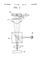
- FIGS. 1 and 2 show focusing states of a conventional optical pickup device of light incident by zero order diffracted light and 1st order diffracted light on a thin disk and a thick disk, respectively.
- a refractive lens 2 and a hologram lens 1 are disposed in sequence along an optical path from each of disks 3a and 3b.
- the hologram lens 1 has a lattice pattern 11 for diffracting light that passes through the hologram lens 1.
- light 4 emitted from a light source passes through the hologram lens 1
- light is divided into a diffracted 1st order light 41 and a non-diffracted zero order light 40, respectively.
- the diffracted 1st order light 41 and the non diffracted zero order light 40 pass through each of the objective lenses 2, the light 41 and 40 are focused with different intensities, thereby forming a focus on the thin disk 3a and on the thick disk 3b.
- the lens device described above can record information on disks having different thicknesses and read out information therefrom using zero order light and 1st order light.
- the efficiency of light use is lowered. That is, since the incident light is divided into zero order light and 1st order light by the hologram lens 1, the actual amount of light used for recording information is only 150%. Also, when information is reproduced, information is included in only one of zero order light and 1st order light. Thus, 1st order light or zero order light without information is detected by a photo detector and the detected light may produce noise.
- the above problem can be overcome by processing the hologram lens of the lens device. However, this requires a high precision process of etching a fine pattern on the hologram, thereby increasing the manufacturing cost.
- an optical device comprising a light source; an objective lens facing a disk having a light passing region divided into central, intermediate and periphery regions respectively corresponding to a near axis area, an intermediate axis area and a far axis area of incident light, wherein the curvature of the central and peripheral regions are optimized for a thin disk and that of the intermediate region is optimized for a thick disk; a photo detector for detecting light reflected from the disk; a beam splitter, disposed between the objective lens and the light source, for transmitting/reflecting light from the light source toward the objective lens and for reflecting/transmitting light reflected from the disks toward the photo detector.
- FIG. 1 is a schematic diagram of a conventional lens device having a hologram lens focusing on a thin disk
- FIG. 2 is a schematic diagram of the lens device of FIG. 1 focusing on a thick disk
- FIG. 3 is a schematic diagram of an optical pickup device according to the present invention.
- FIGS. 4 and 5 are perspective and front views of an objective lens adopted into the optical pickup device according to the present invention.
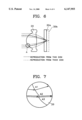
- FIG. 6 is a diagram showing an optical path through the objective lens of the optical pickup device according to the present invention.
- FIG. 7 is a magnified view of portion A in FIG. 6.
- an optical pickup device of the present invention to prevent the generation of spherical aberration from light of an intermediate area when information is reproduced from a thick disk, such that the intermediate area is located between a near area and a far area relative to a central optical axis, the curvature of an intermediate region corresponding to the intermediate area of the light is optimized with respect to the thick disk. Also, the light receiving area of a photo detector is limited so that light of the far axis area cannot be reached thereto when information is reproduced from the thick disk.
- the near axis area represents an area around a central axis of the lens with negligible aberration.
- the far axis area represents an area relatively far from the optical axis compared with that of the near axis area
- the intermediate area represents an area between the near and far axis areas.
- FIG. 3 is a schematic diagram of an optical pickup device according to the present invention.
- an objective lens 20 a beam splitter (separation unit) 60 and a detecting lens 40 are disposed in sequence on an optical path between a disk 30 and a photo detector 90, and a light source 80 is located on another optical path from the beam splitter 60.
- the disk 30 may either be a thin (digital video) disk 30a or a thick (compact) disk 30b.
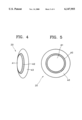
- FIGS. 4 and 5 show perspective and front views of the objective lens 20, respectively.
- the reference symbol WD D denotes the distance between the objective lens 20 and the thin disk 30a
- WD C denotes the distance between the objective lens 20 and the thick disk 30b. That is, in a reading or writing operation, the working distance for the thin disk 30a is larger than that for the thin disk 30b.
- the objective lens 20 has a doughnut- or ring-shaped intermediate region A2 on at least one side, having an outer diameter which is less than the total significant light passing area diameter. Also, a central region A1 and a periphery region A3 are placed inside and outside of the intermediate region A2, respectively.
- the curvatures of the central and peripheral regions A1 and A3 are optimized for a thin digital video disk (DVD), and that of the intermediate region A2 is optimized for a thick compact disk (CD).
- the intermediate region A2 may be divided into a plurality of subregions.
- the photo detector 90 is designed for only receiving light passed through the central and intermediate regions A1 and A2 of the objective lens 20 when information is reproduced from the thick disk, in which light of the far axis area is not detected by the photo detector 90.
- the central region A1 is a circular region
- the intermediate region A2 is a first disk-shaped region
- the periphery region A3 is a second disk-shaped region.
- Table 1 shows lens data at the intermediate region which is optimized for the thick CD 30b
- Table 2 shows lens data at the central and periphery regions A1 and A3 optimized for a thin DVD 30a.
- the references to "front,” “back,” and “disk” represent the front surface of the objective lens 20, the back surface of the objective lens 20 and the surface of the disk, respectively.
- the data for the curved surfaces "front,” “back,” and “disk” refer to the data of the front surface of the objective lens 20 at the intermediate region, the back surface of the lens at the intermediate region A2, and the surface of the thick CD 30b, respectively
- the data for the curved surfaces "front,” “back,” and “disk” refer to the data of the front surface of the objective lens 20 at the central and periphery regions A1 and A3, the back surface of the objective lens 20 at the central and periphery regions A1 and A3, and the surface of the thin DVD 30a, respectively.
- the thick CD and the thin DVD can be compatibly adopted and a signal can be detected without picking up noise regardless of the thickness of the disk.
- the objective lens can be manufactured easily by a general compression or injection molding, thereby reducing manufacturing costs.
Landscapes
- Physics & Mathematics (AREA)
- Optics & Photonics (AREA)
- Optical Head (AREA)
- Lenses (AREA)
- Holo Graphy (AREA)
- Glass Compositions (AREA)
Abstract
An optical pickup device which is efficient in light use having little spherical aberration. The optical pickup device of an optical pickup includes an objective lens, disposed opposite a disk, having a light passing region divided into central, intermediate and periphery regions corresponding to a near axis area, an intermediate axis area and a far axis area of incident light, where the curvature of the central and peripheral regions is optimized for a thin disk and that of the intermediate region is optimized for a thick disk; a light source irradiating light toward a disk through the objective lens; a photo detector for detecting light reflected from the disk; and a beam splitter, disposed between the objective lens and the light source, for transmitting light from the light source toward the objective lens and for diffracting light reflected from the disks toward the photo detector. Therefore, the optical pickup device can be used for both compact disks (CDs) that are thick using light beam passing the near and intermediate regions of said objective lens, and digital video disks (DVDS) that are thin using light beam passing the near and far axis regions of said objective lens, and detect signals without picking up noise regardless of the thickness of the disk.
Description
This application is a Continuation of Ser. No. 08/933,249, filed Sep. 18, 1997, and now is U.S. Pat. No. 5,909,424, which is a Continuation of Ser. No. 08/779,521, filed Jan. 7, 1997.
1. Field of the Invention
The present invention relates to an optical pickup device which is applied to an optical pickup apparatus, and more particularly, to an optical pickup device which enables reading out of information from optical disks having different thicknesses and enables recording information thereon.
In the optical pickup, an objective lens faces a recording surface of an optical disk for focusing light to record information onto the recording surface of the disk or receiving light reflected from the surface of the disk to read information.
2. Description of the Related Art
Recently, research on an optical drive has been conducted in which the drive can seat disks having different thicknesses by adopting a lens device including both a hologram lens and a refractive lens.
FIGS. 1 and 2 show focusing states of a conventional optical pickup device of light incident by zero order diffracted light and 1st order diffracted light on a thin disk and a thick disk, respectively. A refractive lens 2 and a hologram lens 1 are disposed in sequence along an optical path from each of disks 3a and 3b. The hologram lens 1 has a lattice pattern 11 for diffracting light that passes through the hologram lens 1. Thus, while light 4 emitted from a light source (not shown) passes through the hologram lens 1, light is divided into a diffracted 1st order light 41 and a non-diffracted zero order light 40, respectively. While the diffracted 1st order light 41 and the non diffracted zero order light 40 pass through each of the objective lenses 2, the light 41 and 40 are focused with different intensities, thereby forming a focus on the thin disk 3a and on the thick disk 3b.
The lens device described above can record information on disks having different thicknesses and read out information therefrom using zero order light and 1st order light. However, as the incident light is divided into zero order light and 1st order light, the efficiency of light use is lowered. That is, since the incident light is divided into zero order light and 1st order light by the hologram lens 1, the actual amount of light used for recording information is only 150%. Also, when information is reproduced, information is included in only one of zero order light and 1st order light. Thus, 1st order light or zero order light without information is detected by a photo detector and the detected light may produce noise. The above problem can be overcome by processing the hologram lens of the lens device. However, this requires a high precision process of etching a fine pattern on the hologram, thereby increasing the manufacturing cost.
It is an object of the present invention to provide an optical pickup device wherein parts thereof can be manufactured and assembled easily at low cost.
It is another object of the present invention to provide an optical pickup device which has high efficiency of light use and low spherical aberration.
To achieve the above and other objects, there is provided an optical device comprising a light source; an objective lens facing a disk having a light passing region divided into central, intermediate and periphery regions respectively corresponding to a near axis area, an intermediate axis area and a far axis area of incident light, wherein the curvature of the central and peripheral regions are optimized for a thin disk and that of the intermediate region is optimized for a thick disk; a photo detector for detecting light reflected from the disk; a beam splitter, disposed between the objective lens and the light source, for transmitting/reflecting light from the light source toward the objective lens and for reflecting/transmitting light reflected from the disks toward the photo detector.
The above and other objects and advantages of the present invention will become more apparent by describing in detail a preferred embodiment thereof with reference to the attached drawings in which:
FIG. 1 is a schematic diagram of a conventional lens device having a hologram lens focusing on a thin disk;
FIG. 2 is a schematic diagram of the lens device of FIG. 1 focusing on a thick disk;
FIG. 3 is a schematic diagram of an optical pickup device according to the present invention;
FIGS. 4 and 5 are perspective and front views of an objective lens adopted into the optical pickup device according to the present invention;
FIG. 6 is a diagram showing an optical path through the objective lens of the optical pickup device according to the present invention;
FIG. 7 is a magnified view of portion A in FIG. 6.
According to an optical pickup device of the present invention, to prevent the generation of spherical aberration from light of an intermediate area when information is reproduced from a thick disk, such that the intermediate area is located between a near area and a far area relative to a central optical axis, the curvature of an intermediate region corresponding to the intermediate area of the light is optimized with respect to the thick disk. Also, the light receiving area of a photo detector is limited so that light of the far axis area cannot be reached thereto when information is reproduced from the thick disk.
Here, the near axis area represents an area around a central axis of the lens with negligible aberration. Also, the far axis area represents an area relatively far from the optical axis compared with that of the near axis area, and the intermediate area represents an area between the near and far axis areas.
FIG. 3 is a schematic diagram of an optical pickup device according to the present invention. Like a general optical pickup device, an objective lens 20, a beam splitter (separation unit) 60 and a detecting lens 40 are disposed in sequence on an optical path between a disk 30 and a photo detector 90, and a light source 80 is located on another optical path from the beam splitter 60. The disk 30 may either be a thin (digital video) disk 30a or a thick (compact) disk 30b.
In the optical pickup device having the above structure according to the present invention, FIGS. 4 and 5 show perspective and front views of the objective lens 20, respectively. The reference symbol WDD denotes the distance between the objective lens 20 and the thin disk 30a, and WDC denotes the distance between the objective lens 20 and the thick disk 30b. That is, in a reading or writing operation, the working distance for the thin disk 30a is larger than that for the thin disk 30b.
The objective lens 20 has a doughnut- or ring-shaped intermediate region A2 on at least one side, having an outer diameter which is less than the total significant light passing area diameter. Also, a central region A1 and a periphery region A3 are placed inside and outside of the intermediate region A2, respectively. Here, the curvatures of the central and peripheral regions A1 and A3 are optimized for a thin digital video disk (DVD), and that of the intermediate region A2 is optimized for a thick compact disk (CD). Also, depending on circumstances, the intermediate region A2 may be divided into a plurality of subregions. Preferably, the photo detector 90 is designed for only receiving light passed through the central and intermediate regions A1 and A2 of the objective lens 20 when information is reproduced from the thick disk, in which light of the far axis area is not detected by the photo detector 90. The central region A1 is a circular region, the intermediate region A2 is a first disk-shaped region and the periphery region A3 is a second disk-shaped region.
Thus, as shown in FIGS. 6 and 7, when information is reproduced from the thick CD 30b, only light inside the dashed line is focused on the thick CD 30b. Here, since light of the near axis area passes through the objective lens, less spherical aberration is generated, even though the curvature of the central region A1 corresponding to the near axis area is optimized for the thin DVD 30a. Also, when reproducing information from the thin DVD 30a, light passes through the central and peripheral regions A1 and A3 whose curvature is optimized for the thin disk, thereby forming a focus on a surface including information of the thin disk 30a.
When a numerical aperture (NA) of the regions corresponding to the near and intermediate axis areas is less than 0.4, a small focus can be formed on the thick CD 30b, wherein the small focus is optimized for the CD disk. According to experimentation, it is preferable that the width of the ring-shaped intermediate region is greater than 50 μm from the thin DVD 30 a for a stable reproducing characteristic. Also, the data of the objective lens 20 for each region which is optimized for the CD and DVD are summarized in Tables 1 and 2, respectively.
Table 1 shows lens data at the intermediate region which is optimized for the thick CD 30b , and Table 2 shows lens data at the central and periphery regions A1 and A3 optimized for a thin DVD 30a. In these tables, the references to "front," "back," and "disk" represent the front surface of the objective lens 20, the back surface of the objective lens 20 and the surface of the disk, respectively. That is, in Table 1, the data for the curved surfaces "front," "back," and "disk" refer to the data of the front surface of the objective lens 20 at the intermediate region, the back surface of the lens at the intermediate region A2, and the surface of the thick CD 30b, respectively, and in Table 2, the data for the curved surfaces "front," "back," and "disk" refer to the data of the front surface of the objective lens 20 at the central and periphery regions A1 and A3, the back surface of the objective lens 20 at the central and periphery regions A1 and A3, and the surface of the thin DVD 30a, respectively.
As described above, according to the optical pickup device of the present invention, the thick CD and the thin DVD can be compatibly adopted and a signal can be detected without picking up noise regardless of the thickness of the disk. Also, the objective lens can be manufactured easily by a general compression or injection molding, thereby reducing manufacturing costs.
              TABLE 1
______________________________________
Data at the intermediate region of the objective lens
Curved                    Refractive
                                  Aspherical
Surface
      Curvature Thickness Index   Coefficient
______________________________________
front   2.40632 2.600000  1.505   K =    0.00000
                                  A =  -3.51258E-03
                                  B =  -6.19938E-04
                                  C =  -2.32191E-04
                                  D =    0.00000
back  -5.11700  1.563295  1.580   K = -24.72000
                                  A =    4.46350E-03
                                  B =  -3.69750E-03
                                  C =    8.23880E-04
                                  D =  -7.45950E-05
disk  ∞   1.200000  1.550   Not Applicable
______________________________________
              TABLE 2
______________________________________
Data at the central and periphery regions
Curved                  Refractive
                               Aspherical
Surface
      Curvature
               Thickness
                        Index  Coefficient
______________________________________
front 2.09200  2.600000 1.505  K =    -0.872110
                               A =      4.79500E-03
                               B =      6.25260E-05
                               C =      1.24380E-05
                               D =    -1.76880E-04
back  -5.11700 1.563295        K =   -24.72000
                               IC :  Yes
                               CUF =    0.000000
                               A =      4.46350E-03
                               B =    -3.69750E-03
                               C =      8.23880E-04
                               D =    -7.45950E-05
disk   ∞  0.600000 1.550 Not Applicable
______________________________________
Claims (7)
1. An optical pickup device compatible with discs having different thicknesses, comprising:
a light source to emit a light beam;
an objective lens to focus the light beam on the discs having the different thicknesses to optimize optical aberration for a second one of the discs having a thickness greater than that of a first one of the disks; and
a photo detector to detect the light beam reflected from the discs having the different thicknesses.
2. The optical pickup device as claimed in claim 1, wherein the objective lens has at least one region to focus the light beam onto the discs independent of the thicknesses of the discs.
3. The optical pickup device as claimed in claim 1, wherein a first working distance between the objective lens and a near surface of a first one of the discs having a first thickness is greater than a second working distance between the objective lens and a near surface of a second one of the discs having a second thickness greater than the first thickness.
4. An optical pickup device compatible with discs having different thicknesses, comprising:
an objective lens to focus a light beam on the discs having the different thicknesses, wherein the objective lens has a ring region;
wherein a first working distance between the objective lens and a near surface of a first one of the discs having a first thickness is greater than a second working distance between the objective lens and a near surface of a second one of the discs having a second thickness greater than the first thickness.
5. The optical pickup device as claimed in claim 4, wherein the ring region has a different optical characteristic from regions of the objective lens other than the ring region.
6. An optical pickup device compatible with discs having different thicknesses, comprising:
a light source to emit a light beam;
an objective lens to focus the light beam on the discs having the different thicknesses, wherein the objective lens has at least one region to focus the light beam onto the discs independent of the thicknesses of the discs; and
a photodetector to detect the light beam reflected from the discs having the different thicknesses.
7. An objective lens for use in an optical device compatible with optical memory media of different thicknesses, said objective lens having at least one region which focuses light onto one of the optical memory media independent of the thickness of the one optical memory medium, wherein a first working distance between the objective lens and a near surface of a first one of the optical memory media having a first thickness is greater than a second working distance between the objective lens and a near surface of a second one of the optical memory media having a second thickness greater than the first thickness.
Priority Applications (5)
| Application Number | Priority Date | Filing Date | Title |
|---|---|---|---|
| US09/291,031 US6147955A (en) | 1996-02-14 | 1999-04-14 | Optical pickup device to read from and record information to disks of different thicknesses |
| US09/467,385 US6259668B1 (en) | 1996-02-14 | 1999-12-21 | Recording/reproducing apparatus having an optical pickup device to read from and record information to disks of different thicknesses |
| US09/789,522 US6882614B2 (en) | 1996-02-14 | 2001-02-22 | Recording/reproducing apparatus having an optical pickup device to read from and record information to disks of different thicknesses |
| US10/225,177 US8503272B2 (en) | 1996-02-14 | 2002-08-22 | Recording/reproducing apparatus having an optical pickup device to read from and record information to disks of different thicknesses |
| US10/441,111 US8848502B2 (en) | 1996-02-14 | 2003-05-20 | Recording/reproducing apparatus having an optical pickup device to read from and record information to disks of different thicknesses |
Applications Claiming Priority (5)
| Application Number | Priority Date | Filing Date | Title |
|---|---|---|---|
| KR1019960003603A KR100238266B1 (en) | 1996-02-14 | 1996-02-14 | Optics |
| KR96-3603 | 1996-02-14 | ||
| US77952197A | 1997-01-07 | 1997-01-07 | |
| US08/933,249 US5909424A (en) | 1996-02-14 | 1997-09-18 | Optical pickup device and method to read from and record information to disks of different thicknesses |
| US09/291,031 US6147955A (en) | 1996-02-14 | 1999-04-14 | Optical pickup device to read from and record information to disks of different thicknesses |
Related Parent Applications (1)
| Application Number | Title | Priority Date | Filing Date |
|---|---|---|---|
| US08/933,249 Continuation US5909424A (en) | 1996-02-14 | 1997-09-18 | Optical pickup device and method to read from and record information to disks of different thicknesses |
Related Child Applications (1)
| Application Number | Title | Priority Date | Filing Date |
|---|---|---|---|
| US09/467,385 Continuation-In-Part US6259668B1 (en) | 1996-02-14 | 1999-12-21 | Recording/reproducing apparatus having an optical pickup device to read from and record information to disks of different thicknesses |
Publications (1)
| Publication Number | Publication Date |
|---|---|
| US6147955A true US6147955A (en) | 2000-11-14 |
Family
ID=19451249
Family Applications (2)
| Application Number | Title | Priority Date | Filing Date |
|---|---|---|---|
| US08/933,249 Expired - Lifetime US5909424A (en) | 1996-02-14 | 1997-09-18 | Optical pickup device and method to read from and record information to disks of different thicknesses |
| US09/291,031 Expired - Lifetime US6147955A (en) | 1996-02-14 | 1999-04-14 | Optical pickup device to read from and record information to disks of different thicknesses |
Family Applications Before (1)
| Application Number | Title | Priority Date | Filing Date |
|---|---|---|---|
| US08/933,249 Expired - Lifetime US5909424A (en) | 1996-02-14 | 1997-09-18 | Optical pickup device and method to read from and record information to disks of different thicknesses |
Country Status (8)
| Country | Link |
|---|---|
| US (2) | US5909424A (en) |
| JP (7) | JP3068480B2 (en) |
| KR (1) | KR100238266B1 (en) |
| DE (1) | DE19700504C2 (en) |
| FR (1) | FR2744831B1 (en) |
| GB (1) | GB2310308B (en) |
| IT (1) | IT1289866B1 (en) |
| NL (2) | NL1004954C2 (en) |
Cited By (2)
| Publication number | Priority date | Publication date | Assignee | Title |
|---|---|---|---|---|
| US20030210639A1 (en) * | 2002-05-08 | 2003-11-13 | Pentax Corporation | Objective lens for optical pickup |
| US20040165520A1 (en) * | 2003-02-26 | 2004-08-26 | Samsung Electronics Co., Ltd. | Compatible optical pickup |
Families Citing this family (12)
| Publication number | Priority date | Publication date | Assignee | Title |
|---|---|---|---|---|
| US6259668B1 (en) | 1996-02-14 | 2001-07-10 | Samsung Electronics Co., Ltd. | Recording/reproducing apparatus having an optical pickup device to read from and record information to disks of different thicknesses |
| US6304540B1 (en) * | 1998-03-30 | 2001-10-16 | Samsung Electronics Co., Ltd. | Optical pickup compatible with a digital versatile disk and a recordable compact disk using a holographic ring lens |
| KR100514323B1 (en) * | 1997-12-05 | 2005-12-08 | 삼성전자주식회사 | Optical pickup with objective lens compatible with multiple optical discs |
| KR100354534B1 (en) | 1998-03-17 | 2002-12-11 | 삼성전자 주식회사 | Optical pickup for narrow-track optical disk |
| JP4535212B2 (en) * | 1998-09-18 | 2010-09-01 | コニカミノルタホールディングス株式会社 | Objective lens for recording / reproducing optical information recording media |
| KR100804869B1 (en) | 1999-10-06 | 2008-02-20 | 마츠시타 덴끼 산교 가부시키가이샤 | Lens, optical head, optical information recording and reproducing apparatus, and optical information recording medium recording and reproducing method |
| TW490589B (en) * | 2000-05-24 | 2002-06-11 | Konishiroku Photo Ind | Optical pickup apparatus, objective lens, apparatus for reproducing and/or recording optical information recording medium |
| US7116627B2 (en) | 2000-07-08 | 2006-10-03 | Samsung Electronics Co., Ltd. | Compatible optical pickup device using a single light source |
| KR100754158B1 (en) | 2000-12-08 | 2007-09-03 | 삼성전자주식회사 | Optical pickup device capable of detecting and / or correcting spherical aberration |
| KR20030093683A (en) * | 2002-06-05 | 2003-12-11 | 삼성전자주식회사 | Compatible optical pickup |
| KR101312633B1 (en) * | 2007-04-04 | 2013-10-04 | 삼성전자주식회사 | Hologram optical device and compatible optical pickup and optical information storage medium system employing the same |
| JP5393020B2 (en) * | 2007-04-26 | 2014-01-22 | 株式会社リコー | Optical pickup and optical information processing apparatus |
Citations (10)
| Publication number | Priority date | Publication date | Assignee | Title |
|---|---|---|---|---|
| US5161040A (en) * | 1989-01-30 | 1992-11-03 | Seiko Epson Corporation | Optical system with aberration suppression and optical head utilizing the same |
| US5235581A (en) * | 1990-08-09 | 1993-08-10 | Matsushita Electric Industrial Co., Ltd. | Optical recording/reproducing apparatus for optical disks with various disk substrate thicknesses |
| US5303221A (en) * | 1992-06-10 | 1994-04-12 | Pioneer Electronic Corporation | Optical pickup for an optical disc reproducing system |
| US5446565A (en) * | 1993-02-01 | 1995-08-29 | Matsushita Electric Industrial Co., Ltd. | Compound objective lens having two focal points |
| JPH07302437A (en) * | 1994-03-11 | 1995-11-14 | Toshiba Corp | Optical head device and lens |
| US5659533A (en) * | 1996-07-23 | 1997-08-19 | Sampo Corporation | Method of using a single pick-up head to read and store data on discs of different thicknesses and structure of a pick-up head apparatus therefor |
| US5665957A (en) * | 1995-08-30 | 1997-09-09 | Samsung Electronics Co., Ltd. | Lens device comprising light blocking means and an optical pickup apparatus using the lens device |
| US5724335A (en) * | 1995-10-25 | 1998-03-03 | Konica Corporation | Objective lens for recording and reproducing for use in an optical information recording medium |
| US5777973A (en) * | 1995-12-07 | 1998-07-07 | Samsung Electronics Co., Ltd. | Reproducing and recording optical pickup compatible with discs having different thicknesses |
| US5796683A (en) * | 1996-03-26 | 1998-08-18 | Sanyo Electric Co., Ltd. | Magneto-optical recording device having a controllable polarizing filter |
Family Cites Families (9)
| Publication number | Priority date | Publication date | Assignee | Title |
|---|---|---|---|---|
| JPS6273429A (en) * | 1985-09-26 | 1987-04-04 | Toshiba Corp | Position detector for optical pickup |
| JP3266627B2 (en) * | 1991-10-11 | 2002-03-18 | 株式会社日立製作所 | Information playback device |
| US5349592A (en) * | 1992-02-27 | 1994-09-20 | Kabushiki Kaisha Toshiba | Super-resolution optical element for use in image forming apparatus |
| JPH08248307A (en) * | 1995-03-10 | 1996-09-27 | Sony Corp | Objective lens, optical head device, and optical disk reproducing device |
| CA2202288C (en) * | 1995-08-30 | 2000-09-26 | Chul-Woo Lee | Lens device and an optical pickup apparatus using the lens device |
| US5587981A (en) * | 1995-09-05 | 1996-12-24 | Kamatani; Yasuo | Multi-standard optical disk reading method having distinction process |
| US5966362A (en) * | 1995-11-02 | 1999-10-12 | Konica Corporation | Optical system for recording and reproducing for use in optical information recording medium |
| KR0179138B1 (en) * | 1995-12-01 | 1999-04-15 | 구자홍 | Objective |
| JP2806422B2 (en) * | 1996-01-19 | 1998-09-30 | 日本電気株式会社 | Condensing lens for optical disc |
-
1996
- 1996-02-14 KR KR1019960003603A patent/KR100238266B1/en not_active Expired - Lifetime
-
1997
- 1997-01-03 GB GB9700072A patent/GB2310308B/en not_active Expired - Lifetime
- 1997-01-08 IT IT97MI000014A patent/IT1289866B1/en active IP Right Grant
- 1997-01-08 NL NL1004954A patent/NL1004954C2/en not_active IP Right Cessation
- 1997-01-09 DE DE19700504A patent/DE19700504C2/en not_active Expired - Lifetime
- 1997-01-10 FR FR9700186A patent/FR2744831B1/en not_active Expired - Lifetime
- 1997-01-21 JP JP9009000A patent/JP3068480B2/en not_active Expired - Fee Related
- 1997-09-18 US US08/933,249 patent/US5909424A/en not_active Expired - Lifetime
-
1998
- 1998-08-03 NL NL1009796A patent/NL1009796C2/en not_active IP Right Cessation
- 1998-11-18 JP JP10328564A patent/JPH11339298A/en active Pending
-
1999
- 1999-04-14 US US09/291,031 patent/US6147955A/en not_active Expired - Lifetime
-
2001
- 2001-01-17 JP JP2001009431A patent/JP2001236686A/en active Pending
- 2001-01-17 JP JP2001009432A patent/JP2001236687A/en active Pending
-
2002
- 2002-06-04 JP JP2002163543A patent/JP2003050347A/en active Pending
- 2002-06-04 JP JP2002163542A patent/JP2003051135A/en active Pending
- 2002-12-18 JP JP2002367265A patent/JP2003178483A/en active Pending
Patent Citations (10)
| Publication number | Priority date | Publication date | Assignee | Title |
|---|---|---|---|---|
| US5161040A (en) * | 1989-01-30 | 1992-11-03 | Seiko Epson Corporation | Optical system with aberration suppression and optical head utilizing the same |
| US5235581A (en) * | 1990-08-09 | 1993-08-10 | Matsushita Electric Industrial Co., Ltd. | Optical recording/reproducing apparatus for optical disks with various disk substrate thicknesses |
| US5303221A (en) * | 1992-06-10 | 1994-04-12 | Pioneer Electronic Corporation | Optical pickup for an optical disc reproducing system |
| US5446565A (en) * | 1993-02-01 | 1995-08-29 | Matsushita Electric Industrial Co., Ltd. | Compound objective lens having two focal points |
| JPH07302437A (en) * | 1994-03-11 | 1995-11-14 | Toshiba Corp | Optical head device and lens |
| US5665957A (en) * | 1995-08-30 | 1997-09-09 | Samsung Electronics Co., Ltd. | Lens device comprising light blocking means and an optical pickup apparatus using the lens device |
| US5724335A (en) * | 1995-10-25 | 1998-03-03 | Konica Corporation | Objective lens for recording and reproducing for use in an optical information recording medium |
| US5777973A (en) * | 1995-12-07 | 1998-07-07 | Samsung Electronics Co., Ltd. | Reproducing and recording optical pickup compatible with discs having different thicknesses |
| US5796683A (en) * | 1996-03-26 | 1998-08-18 | Sanyo Electric Co., Ltd. | Magneto-optical recording device having a controllable polarizing filter |
| US5659533A (en) * | 1996-07-23 | 1997-08-19 | Sampo Corporation | Method of using a single pick-up head to read and store data on discs of different thicknesses and structure of a pick-up head apparatus therefor |
Cited By (4)
| Publication number | Priority date | Publication date | Assignee | Title |
|---|---|---|---|---|
| US20030210639A1 (en) * | 2002-05-08 | 2003-11-13 | Pentax Corporation | Objective lens for optical pickup |
| US7224662B2 (en) | 2002-05-08 | 2007-05-29 | Pentax Corporation | Objective lens for optical pickup |
| US20040165520A1 (en) * | 2003-02-26 | 2004-08-26 | Samsung Electronics Co., Ltd. | Compatible optical pickup |
| US7505390B2 (en) * | 2003-02-26 | 2009-03-17 | Samsung Electronics Co., Ltd. | Compatible optical pickup |
Also Published As
| Publication number | Publication date |
|---|---|
| JP2003051135A (en) | 2003-02-21 |
| GB2310308A (en) | 1997-08-20 |
| GB2310308B (en) | 1998-02-04 |
| GB9700072D0 (en) | 1997-02-19 |
| FR2744831B1 (en) | 1999-05-07 |
| JPH09219035A (en) | 1997-08-19 |
| JP2003178483A (en) | 2003-06-27 |
| JP2003050347A (en) | 2003-02-21 |
| JP2001236687A (en) | 2001-08-31 |
| NL1004954C2 (en) | 1998-12-10 |
| KR100238266B1 (en) | 2000-02-01 |
| JP3068480B2 (en) | 2000-07-24 |
| KR970063070A (en) | 1997-09-12 |
| JPH11339298A (en) | 1999-12-10 |
| DE19700504A1 (en) | 1997-08-21 |
| US5909424A (en) | 1999-06-01 |
| DE19700504C2 (en) | 2002-05-16 |
| NL1009796A1 (en) | 1998-09-01 |
| ITMI970014A1 (en) | 1998-07-08 |
| IT1289866B1 (en) | 1998-10-19 |
| JP2001236686A (en) | 2001-08-31 |
| NL1004954A1 (en) | 1997-08-15 |
| FR2744831A1 (en) | 1997-08-14 |
| NL1009796C2 (en) | 1999-05-19 |
Similar Documents
| Publication | Publication Date | Title |
|---|---|---|
| CN100375169C (en) | Optical pickup device compatible with optical recording media of different thicknesses | |
| US5737294A (en) | Objective lens with two numerical apertures for reading/writing two optical discs | |
| US6285646B1 (en) | Optical pickup using objective lens compatible with a plurality of optical disks | |
| JP3319686B2 (en) | Two-position imaging objective lens for optical pickup | |
| US6147955A (en) | Optical pickup device to read from and record information to disks of different thicknesses | |
| US6816449B2 (en) | Optical pickup compatible with a digital versatile disk and a recordable compact disk using a holographic ring lens | |
| JP2001209936A (en) | Discrimination method for discs having different thicknesses, focus detection method, reproduction method, and recording method | |
| JPH09237431A (en) | Objective lens device, optical pickup device to which the same is applied, and objective lens manufacturing method | |
| JP3787925B2 (en) | Objective lens device and recording / reproducing device | |
| CN100403418C (en) | Objective lenses compatible with optical recording media of various thicknesses | |
| US6882614B2 (en) | Recording/reproducing apparatus having an optical pickup device to read from and record information to disks of different thicknesses | |
| US5802037A (en) | Optical detector with two detecting regions for reproducing and recording information on two kinds of disks having different thicknesses | |
| JP3919276B2 (en) | Optical head and optical disk apparatus | |
| JP3896617B2 (en) | Optical pickup device | |
| EP1056075A1 (en) | Optical pick-up apparatus and correction lens for use in the apparatus | |
| JPH10162409A (en) | Optical element and optical pickup device | |
| EP0996120A1 (en) | Optical pickup compatible with a digital versatile disk and a recordable compact disk using a holographic ring lens | |
| KR100234254B1 (en) | Playback signal detection method for disc compatibility and optical pickup for high density recording / playback using the same | |
| HK1015062A1 (en) | Optical pickup apparatus compatible with a digital versatile disk | |
| JP2000331367A (en) | Optical information recording / reproducing device |
Legal Events
| Date | Code | Title | Description |
|---|---|---|---|
| STCF | Information on status: patent grant |
Free format text: PATENTED CASE |
|
| FPAY | Fee payment |
Year of fee payment: 4 |
|
| FPAY | Fee payment |
Year of fee payment: 8 |
|
| FEPP | Fee payment procedure |
Free format text: PAYER NUMBER DE-ASSIGNED (ORIGINAL EVENT CODE: RMPN); ENTITY STATUS OF PATENT OWNER: LARGE ENTITY Free format text: PAYOR NUMBER ASSIGNED (ORIGINAL EVENT CODE: ASPN); ENTITY STATUS OF PATENT OWNER: LARGE ENTITY |
|
| FPAY | Fee payment |
Year of fee payment: 12 |